Article

Dynamic Response Characteristics of the Hydraulic Rotary System of an Azimuth Thruster for a Dynamic Positioning Vessel

College of Shipbuilding Engineering, Harbin Engineering University, Harbin 150001, China
*
Author to whom correspondence should be addressed.
J. Mar. Sci. Eng. 2023, 11(2), 399; https://doi.org/10.3390/jmse11020399
Submission received: 8 January 2023 / Revised: 29 January 2023 / Accepted: 9 February 2023 / Published: 11 February 2023
(This article belongs to the Special Issue Advances in Marine Propulsion)

Abstract

:
The composition characteristics and working principle of the hydraulic rotary system of the azimuth thruster were analyzed. The mathematical model of the rotary dynamic system of the pump-controlled hydraulic motor driving the gear reduction mechanism was established. Additionally, a fast tracking method for the azimuth angle of the azimuth thruster was proposed to analyze the rotary azimuth angle, angular velocity and dynamic response characteristics of the hydraulic system for different desired azimuth angles. The simulation results show that the established dynamic model can simulate the rotary motion response process of the real thruster, and can realize the rapid and accurate tracking of the azimuth angle. At the same time, the physical constraints of the rotary dynamic response were established. It provides an important reference for research on the motion control methods of dynamic positioning vessels.

1. Introduction

Dynamic positioning has gradually replaced traditional mooring in recent years with the increasing difficulty of deep-sea development and has been widely used in many applications, such as diving support, drilling platforms, remotely operated vehicle support and pipe laying. At present, there are more than 2000 ships equipped with dynamic positioning systems, showing a rapid trend toward the use of such systems. To realize motion control with three degrees of freedom in the horizontal plane, a dynamic positioning ship is generally installed with multiple azimuth vector thrusters [1], with the advantage being that the thrusters can output horizontal thrust in any direction through the control of their rotation by a hydraulic rotary dynamic system. The hydraulic rotary dynamic system of the azimuth vector thruster is a typical nonlinear inertial response link, and its rotary motion response inevitably has lag. When designing the dynamic positioning controller and thrust allocation strategy, if physical constraints such as the rotation speed and rotation direction of the thruster are not fully considered, there will be a large deviation in the response of the thruster from the intended outcome, which will adversely affect the positioning ability of the dynamic positioning vessel. In severe cases, this will lead to the failure of dynamic positioning and even catastrophic marine accidents. Therefore, the rotary dynamic response characteristics and physical constraints of the azimuth vector thruster must be considered when studying the motion control and thrust allocation method of the dynamic positioning vessel [2].
B. Ye, J. Xiong et al. [3] proposed a thrust allocation method based on a weighted pseudo-inverse algorithm, considering that the pseudo-inverse method cannot optimize the azimuth angle and taking the propeller and environmental load into account. By combining the optimization of the azimuth angle with the optimization of the thrust, a reasonable and effective allocation of the thrust is realized and the energy consumption and wear are minimized. Y. Yu et al. [4] studied the adjustable pitch azimuth thruster used on a high-power marine engineering platform and analyzed the composition and implementation of the high-power azimuth thruster system. S. W. Kim and M. H. Kim [5] proposed the penalty programming thrust allocation method and implemented the method in a fully coupled vessel–riser–mooring time-domain simulation program with dynamic positioning control. Compared with pseudo-inverse and quadratic programming, the penalty programming was shown to minimize fuel consumption under both 100-year and 1-year storm conditions. M. Fu et al. [6] studied the cycloidal propeller model and applied the sequential quadratic programming (SQP) algorithm to the thrust allocation of a cycloidal propeller. X. Li et al. [7] analyzed the dynamic response of a hydraulic thruster under various states by establishing a simulation model of the servo control hydraulic thruster of a remotely operated vehicle. F. Arditti et al. [8] established thruster–hull, thruster–current and thruster–thruster interaction models and used the SQP algorithm with slack variables to solve the nonlinear optimization problem. D. Gao et al. [9] proposed an improved non-dominated sorting genetic algorithm II (INSGA-II) thrust allocation strategy. In differential evolution, they introduced the differential mutation operator to replace polynomial mutation in NSGA-II, which improved the local optimization of the algorithm. E. Qiu [10] designed software for the simulation of the dynamic response of an underwater thruster and considered simulations of the thruster turbulence, dynamic response, thruster blade load and response execution in the design process. P. Koshorrek et al. [11] analyzed a thrust allocation algorithm using the dynamic characteristics of the Voith Schneider propeller and adopted a two-step approach comprising quadratic programming optimization and external tracking algorithms for the calculation of power-optimal propulsion control.
Z. Tang et al. [12] proposed a binary thrust efficiency function that deals with both the front propeller angle and rear propeller angle to describe the thrust loss. In their approach, the thrust efficiency function is obtained in a model test and approximated using a radial basis function (RBF) neural network. The SQP algorithm is used to solve the corresponding thrust allocation problem. G. Xia [13] proposed a thrust allocation method based on the improved genetic algorithm for the thrust allocation of the main propeller and rudder of engineering ships, where the optimal solution obtained at the last sampling time is inherited at the next sampling time. This method can effectively solve the fluctuation in the results of a genetic algorithm in continuous time. F. Ding [14] combined the traditional genetic algorithm with the pseudo-inverse algorithm to determine the optimal direction of each propeller. Through solving the optimal direction, the thrust of the propeller is calculated using the quadratic programming algorithm. Y. Chen [15] introduced the idea of group bias and designed an adaptive group bias thrust allocation algorithm based on energy optimization, which can adaptively adjust the bias to generate zero thrust and reduce the energy consumption of the thruster. X. Hu [16] developed a dynamic positioning robust nonlinear control method by combining command filtered vectorial backstepping with a disturbance observer and an auxiliary dynamic system, and solved the nonlinear control problem of the dynamic characteristics of the thruster system of the dynamic positioning ship with model parameter uncertainty. Y. Tuo [17] proposed an improved global artificial fish swarm algorithm with jumping and swallowing behaviors. The simulation results show that the improved algorithm is more likely to find a globally optimal solution and has better convergence efficiency and global searching ability. Z. Tang [18] proposed an optimized thrust allocation algorithm based on an RBF neural network and SQP to improve the traditional forbidden zone method. The RBF neural network is used to approximate the thrust efficiency function and the SQP algorithm to solve the nonlinear optimization problem. A. Haseltalab et al. [19] adopted several linearization techniques, so that the quadratic programming method could be used to solve the optimization problems of model predictive control and thrust allocation. The thrust allocation problem is calculated in a limited time range, and problems of power consumption, operation constraints and changes in the actuator angle and speed can be solved. R. Skulstad et al. [20] proposed a static neural network for the control allocation of over-actuated vessels to measure the thrust and command of thrusters during the trial operation of simulated ships and to collect data for the training of neural networks. The network was then trained and the virtual force commands were converted from the motion controller to a single thruster command. B. Zhao [21] proposed a new thrust allocation method for non-rotatable thrusters, which uses a cost function of the modified thrust allocation problem to allocate thrust to non-rotatable thrusters in the case of no power constraints and thus to deal with thrust constraints. This method runs recursively to minimize allocation errors. M. T. Vu et al. [22] proposed the nonlinear dynamic and robust positioning control of the over-actuated autonomous underwater vehicle under the effects of ocean current and model uncertainty.
In studying the optimal thrust allocation method of the dynamic positioning ship, the literature cited above has considered constraints such as the forbidden zone of the thruster and the minimum energy consumption but not the effect of the thruster rotation direction, or it has only imposed a hypothetical maximum rotation speed of the thruster. There is a lack of research on the rotary dynamic characteristics of a real thruster. This paper takes the Wärtsilä FS-3510 azimuth vector thruster installed on HYSY 286 as the research object. According to the structural characteristics of the hydraulic rotary deceleration system, a simulation model of the rotary dynamic system of the azimuth thruster is constructed considering the flow rate, pressure, motor speed and load of the hydraulic system. Considering the actual control frequency requirement of a dynamic positioning ship, how to realize the asynchronous simulation control of the ship dynamic positioning control system and azimuth thruster rotary hydraulic dynamic system is studied. Finally, the dynamic response process and the characteristics of the rotation angle, angular velocity and rotation direction of the vector thruster are analyzed, and the physical constraints of the rotary dynamic system of the azimuth vector thruster are given.
In this paper, firstly, we introduce the composition and working principle of the FS-3510 azimuth thruster, and establish the mathematical model of its hydraulic rotary system. Next, the motion controller of the hydraulic rotary system is designed, and the control strategy of its azimuth optimization is proposed. Then, we verify the correctness of the model and the reliability of the control method in the simulation software written in C++. Finally, we obtain an optimized control method of the thruster and the rotary rate constraint conditions of the thruster in the thrust allocation of the dynamic positioning system.

2. Composition and Working Principle of FS-3510 Azimuth Vector Thruster

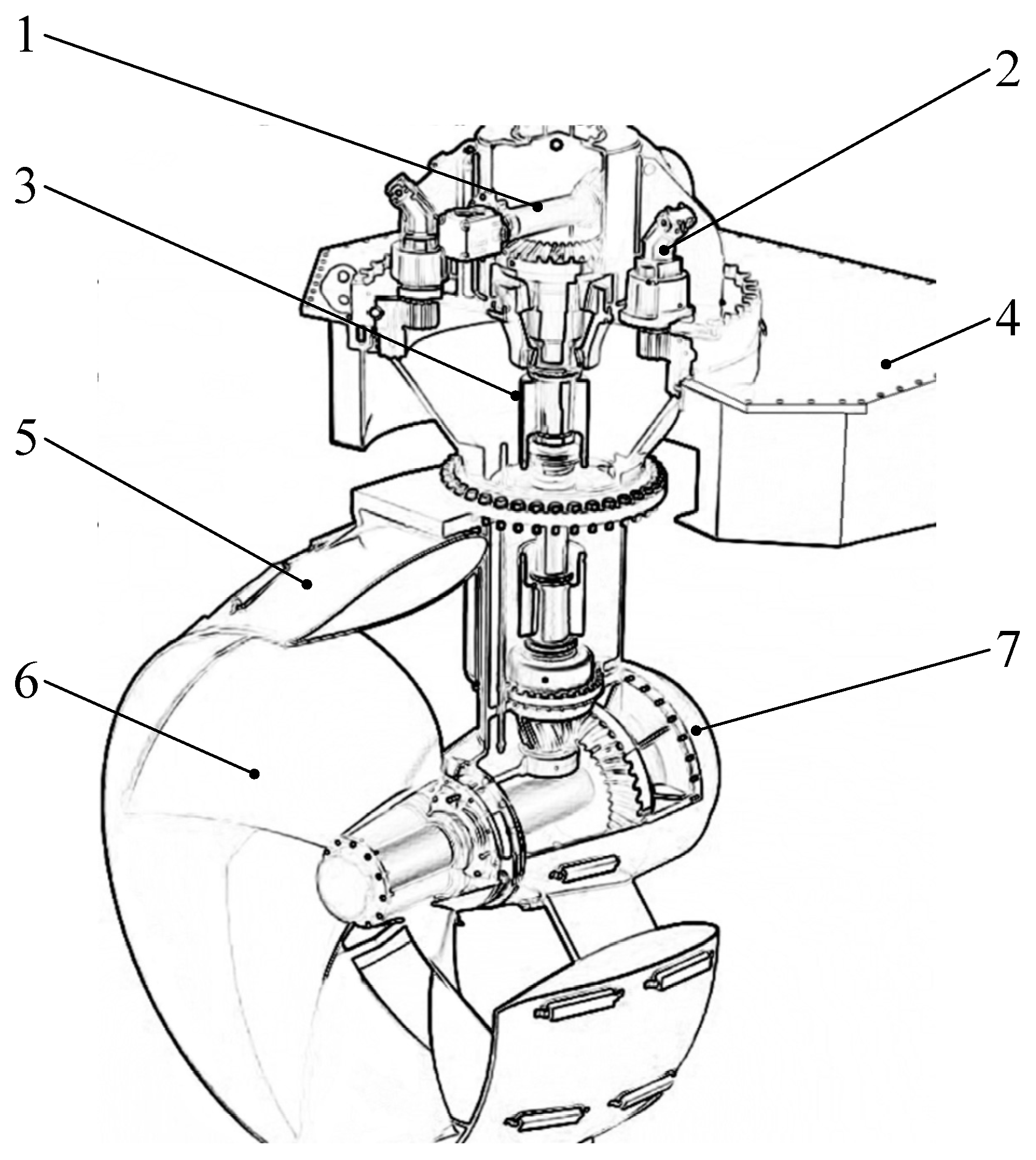
2.1. Composition of the Azimuth Vector Thruster

HYSY286 is equipped with five thrusters, two of which are FS-3510 azimuth thrusters produced by Wärtsilä. The FS-3510 azimuth thruster has two functions: (1) The speed of the propeller is adjusted by the frequency converter in driving the motor, such that the thrust of the propeller can be adjusted. (2) The motor is driven to adjust the rotation of the propeller through the hydraulic rotary dynamic system and thus to adjust the azimuth angle. The FS-3510 azimuth thruster mainly comprises shafting components, and its structure is shown in Figure 1.
The propulsion system of the azimuth vector thruster mainly comprises prime movers and thrusters. Its main function is to generate enough thrust and torque to resist environmental forces and drive the vessel. The prime mover mainly provides power to the ship’s propulsion mechanism, which converts electrical energy into kinetic energy. The thruster converts the torque provided by the prime mover into thrust and torque which drive the motion of the ship.
The working pressure of the rotary hydraulic system of the FS-3510 azimuth thruster is 21 MPa, the maximum flow rate is 418 L/min and the power is 107 kW. The flow rate of each hydraulic motor is 56 L/min, and the FS-3510 rotary system is equipped with six hydraulic motors in total. The hydraulic pump is an A4VG constant pressure variable pump (Rexroth Company), the hydraulic motor is an A2FM-12 quantitative hydraulic motor (Rexroth Company) and the reducer is a GFT-0009-T2 compact hydrostatic traveling mechanism reducer (Rexroth Company). The maximum flow of the thruster rotary hydraulic system is 450 L/min.

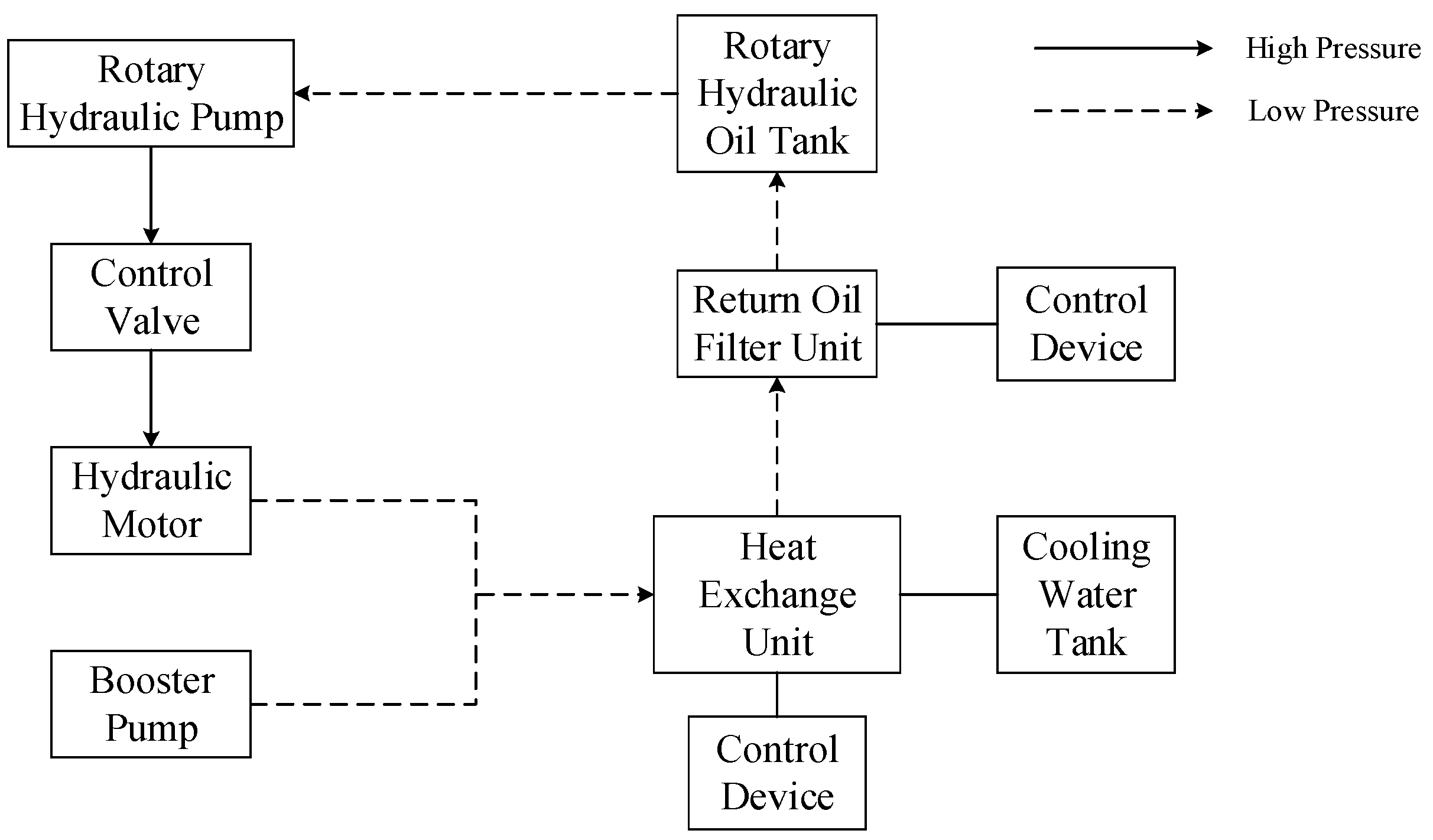
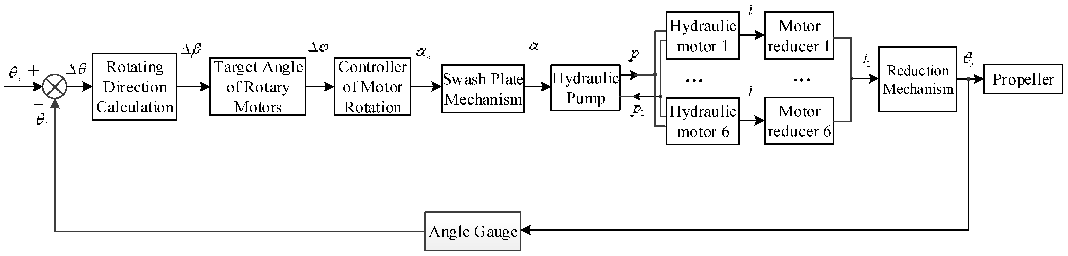
2.2. Composition and Working Principle of the Rotary System

The system mainly controls the rotation of the propeller to meet the thrust direction command issued by the bridge controller, so as to ensure the effective implementation of thrust allocation. The pump-controlled hydraulic rotary dynamic system has two loop systems, as shown in Figure 2.
The first hydraulic oil circuit is the closed-loop oil circuit system that flows from the hydraulic pump to the hydraulic motor. The booster pump and the oil supply line compensate for the leakage of the hydraulic pump and hydraulic motor. The control valve is used to control the flow of hydraulic oil in the circuit. The hydraulic motor drives the deceleration mechanism to rotate through the hydraulic oil, and the return oil directly returns to within the hydraulic pump. The control device can adjust the rotation direction.
The booster pump in the second hydraulic oil circuit compensates for the hydraulic oil (in the rotary oil tank) in the low-pressure oil side. The high-temperature oil in the return oil circuit is cooled by the heat exchange unit, cleaned by the filter unit and returned to the oil tank. Cooling water is provided by the freshwater cooling system of the ship.

3. Mathematical Model of the Propeller Rotary Dynamic System

3.1. Mathematical Modeling of the Pump-Controlled Hydraulic Motor

The following assumptions are made to facilitate the study of the transfer equation of the swash plate swing angle of the variable pump and the output angle of the hydraulic motor [24].
  • The friction loss, pipeline dynamics and fluid quality effects are ignored for all connecting pipes;
  • It is assumed that the internal and external discharges of the hydraulic motor are laminar flows;
  • It is assumed that the two oil return pipelines are exactly the same and that the total volumes of the two chambers comprising a pump, motor and pipeline are the same. The pressure, temperature and bulk elastic modulus of the hydraulic oil in the chamber are constant, and the temperature and density of the oil are constant;
  • It is assumed that the oil supply system responds in real time, the oil supply pressure is constant, and the pressure on the low-pressure side is equal to the oil supply pressure;
  • The effect of structural flexibility is ignored;
  • It is assumed that the phenomenon of pressure saturation does not occur.
It holds for the high-pressure chamber of the hydraulic motor that
n p D p C i P ( p 1 p s ) C e P p 1 C i M ( p 1 p s ) C e M p 1 D M d θ M d t = V 0 β e d p 1 d t ,
where n p is the rotational speed of the pump, rad/s; D p is the displacement of the variable pump, m3/rad; D M is the displacement of the motor, m3/rad; V 0 is the volume of a chamber (including a pump chamber, motor chamber and main pipeline), m3; p 1 is the pressure of the oil inlet chamber (i.e., the load pressure), Pa; p s is the oil charge pressure, Pa; C i p is the internal leakage coefficient of the pump, (m3/s)/Pa; C i M is the internal leakage coefficient of the motor, (m3/s)/Pa; C e p is the external leakage coefficient of the pump, (m3/s)/Pa; C e M is the external leakage coefficient of the motor, (m3/s)/Pa; θ M is the rotation angle of the motor shaft, degrees; and β e is the equivalent bulk elastic modulus, N/m2 (Pa).
The displacement of the variable pump is expressed as
D p = α k p ,
where α is the swing angle of the pump variable mechanism, degrees, and k p is the displacement gradient of the pump, m3/rad2.
Combining Equations (1) and (2) and ignoring the pressure of the charge pump (i.e., p s = 0 ) yields
n p α k p ( C i P + C e P + C i M + C e M ) p 1 D M d θ M d t = V 0 β e d p 1 d t .
The Laplace transformation of Equation (3) gives
α n p k p = D M s θ M + C t p 1 + V 0 β e s p 1 ,
where C t = C i t + C e t is the total leakage coefficient, C i t = C i P + C i M is the total internal leakage coefficient and C e t = C e P + C e M is the total external leakage coefficient.
Assuming that there is no leakage from the hydraulic motor and hydraulic pump, Equation (4) is rewritten as
α n p k p = D M s θ M + V 0 β e s p 1 .

3.2. Mathematical Modeling of the Hydraulic Motor Drive Deceleration Mechanism and Load

The relevant literature gives a balance equation of the hydraulic motor and load force as
T g = ( p 1 p s ) D M = J d θ M 2 d t 2 + B M d θ M d t + θ ˙ M | θ ˙ M | ( p 1 + p s ) C f D M + G θ M + T L ,
where T g is the theoretical torque of the motor; J is the sum of the equivalent moment of inertia of the hydraulic motor and the load; B M is the viscous damping torque coefficient on the hydraulic motor shaft, N·m·s/rad; C f is the internal friction factor of the motor; T L is the external load torque of the hydraulic motor; and G is the elastic load coefficient of the hydraulic motor, G = 0 .
The friction torque in Equation (6) is nonlinear, and the value of C f is generally small. In the linear analysis, we let C f = 0 while ignoring the pressure of the charge pump (i.e., p s = 0 ), and the Laplace transformation of Equation (6) gives
p 1 D M = J s 2 θ M + B M s θ M + T L .
Equations (4) and (7) give the relationship between the variable pump and the hydraulic motor:
{ α n p k p = D M s θ M + C t p 1 + V 0 β e s p 1 p 1 D M = J s 2 θ M + B M s θ M + T L .
If the leakage of the hydraulic system and the external load on the motor shaft are ignored, Equations (5) and (7) yield
α = [ D M p 1 D M β e + V 0 p 1 ( J s 2 + B M s ) ] n p k p β e ( J s + B M ) .
According to the main technical parameters of the FS-3510 fixed pitch azimuth vector thruster, the technical parameters of the pump-controlled hydraulic-motor-driven reduction gear are obtained as given in Table 1.

4. Controller Design and Azimuth Angle Optimization Control Strategy of the Rotary Dynamic System

4.1. Azimuth Angle Optimization Control Strategy of the Azimuth Thruster

According to Δ θ = θ d θ f , the deviation Δ θ between the target azimuth angle and the actual azimuth angle of the azimuth thruster is obtained. The deviation is input into the target azimuth optimization calculation module to obtain the rotation angle Δ β of the azimuth thruster. The target deviation is optimized to reduce the wearing of the thruster and the response time of the thruster rotation. The optimization formula is
Δ β = { Δ θ π Δ θ π Δ θ 2 π π < Δ θ 2 π Δ θ + 2 π 2 π Δ θ < π .
The main idea of azimuth optimization is to determine the direction of rotation by comparing the angular deviations in the clockwise and counterclockwise directions, so that the thruster rotates in the direction with the smallest deviation for each rotation direction. The gyration response time of the azimuth thruster is shortened, which in turn shortens the response time of the dynamic positioning control system, and the control accuracy of the dynamic positioning system is improved.

4.2. Design of the Azimuth Angle Controller for the Azimuth Thruster

The rotary mechanism of the azimuth thruster belongs to the hydraulic control device, which controls the rotation angle of the thruster by controlling the displacement of the hydraulic motor. The difference between the expected azimuth angle and the actual azimuth angle assigned by the thrust allocation module to the thruster is input to the azimuth angle optimization module, and the angle through which the hydraulic motor needs to rotate is then calculated. The deviation in the rotation angle of the feedback hydraulic motor is then input to the proportional–derivative (PD) controller, and the controller output command is transmitted to the calculation module of the hydraulic pump displacement. The displacement of the hydraulic pump is thus obtained, and the actual rotation angle, angular acceleration and output torque of the motor are obtained through the hydraulic motor module. Finally, the actual azimuth angle of the azimuth thruster is calculated.
A PD controller is selected as the hydraulic motor control which has a large lag. The PD control design is
α d = K P e ( t ) + K D d e ( t ) d t .
The parameters of the PD controller can be divided into two cases. According to the expected angle deviation, the design parameters of the controller are
K P = { 0.001 | Δ β | π 2 0.002 | Δ β | > π 2 , K D = { 0.00028 | Δ β | π 2 0.0005 | Δ β | > π 2 .

4.3. Design of a Rotation Simulation System for the Azimuth Vector Thruster Considering a Dynamic Positioning System

The azimuth vector thruster studied in this paper is finally applied to the development of a dynamic positioning simulator to realize the tasks of ship dynamic positioning and maneuvering in a virtual simulation environment. Generally, the control period of the dynamic positioning system is 0.5–1.0 s, but according to relevant simulation research, the minimum simulation step size of the hydraulic simulation system should be no more than 0.01 s. Therefore, the response frequency of the hydraulic control system of the azimuth vector thruster in this paper is approximately 100 times that of the dynamic positioning system, and it is thus necessary to simulate different frequency systems simultaneously in the simulation process, as shown in Figure 3.
In Figure 3, the dynamic simulation system of the azimuth thruster is divided into internal and external loop control. The external loop formula calculates the desired deviation and then the angle deviation through which the hydraulic motor needs to rotate, with control frequency of 1 Hz. The internal loop is the pump-controlled hydraulic motor control system module, and the control frequency of the hydraulic dynamic simulation system is 100 Hz. Using this asynchronous simulation method, the full rotation dynamic simulation module can be directly embedded into the dynamic positioning simulation system.
In Figure 3, the method of rotating direction calculation is shown as Equation (10); the input rotary direction calculation is
Δ θ = θ d θ f ,
where θ f = θ t and θ t is the real time azimuth angle of the thruster.
The input of the PD controller is obtained from
Δ φ = k Δ β ,
where k is total reduction ratio of the azimuth thruster. Additionally, Δ δ is the output of the PD controller, that is, the deflection angle of the swashplate controlled by the motor.
The transfer function of the hydraulic motor system is shown as Equation (9).
The real time azimuth angle of the thruster is
θ t = θ M k ,
where θ M is the rotary angle of hydraulic motors.

5. Analysis of the Hydraulic Rotary Dynamic Simulation Model

5.1. Hydraulic Rotary Dynamic Simulation System

According to the characteristics of the hydraulic rotary system of the azimuth thruster, a mathematical model of the dynamic system of the pump-controlled hydraulic motor driving the gear reduction mechanism for rotational motion is established. The rapid control of the target azimuth angle is realized, and the motion law of the hydraulic rotary dynamic control system of the azimuth thruster can be accurately and effectively simulated, as shown in Figure 4.
The difference between the assigned rotation angle of each propeller output by the thrust allocation module and the actual rotation angle of the propeller measured by the measurement module is introduced into the hydraulic rotation system model of the azimuth thruster. Through the target azimuth angle optimization module, swash plate angle control module and variable module, the swing angle of the variable pump mechanism is obtained, and the swing angle is converted into the pressure difference output by the hydraulic pump. The six hydraulic motors are driven by hydraulic pressure to drive the deceleration mechanism to rotate such that the propeller rotates to the target azimuth angle. Finally, a dynamic system simulation model of the pump-controlled hydraulic motor driving the gear reduction mechanism for rotary motion is established.
The transfer function of the swash plate is shown as
α = 1 T 1 s + 1 α d .
The output flow of the hydraulic pump unit is obtained from
Q p = n p α k p .
The pressure difference in the pump output is
Δ p = p 1 p s .
The total reduction ratio of the azimuth thruster is derived from
k = i 1 × i 2 .
where i 1 is the gear reduction ratio of the hydraulic motor and i 2 is the reduction ratio of the reduction gear mechanism.

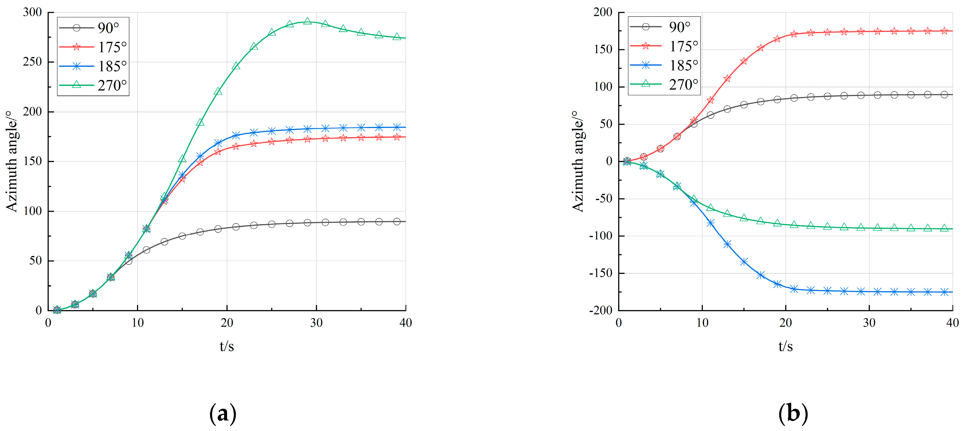
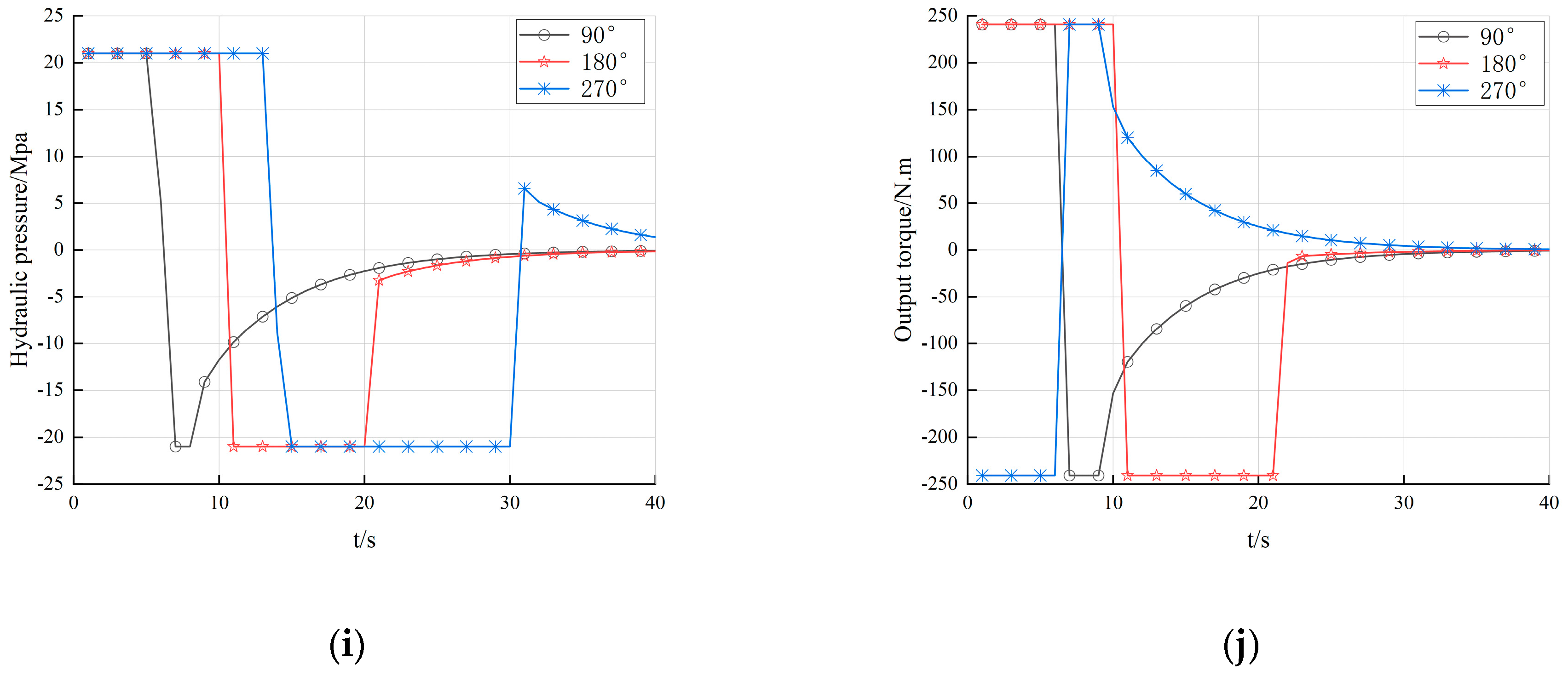
5.2. Simulation of Optimal Control Strategies with and without the Azimuth Rotation Direction

The parameters in Table 1 were inputted to the established simulation system. For the convenience of observation, all of the radians in this paper were converted into degrees of input and output. For the initial azimuth angle of the thruster set at 0° and t = 0, target azimuth angles of 90°, 175°, 185° and 270° were inputted to the simulation system. The dynamic responses of the rotation angle, rotation rate and hydraulic flow rate were analyzed with and without optimization of the azimuth angle, as shown in Figure 5a–j.
In Figure 5a, without optimization of the rotary direction, the target azimuth angles are 90°, 175°, 185° and 270°, and the actual azimuth angle smoothly approaches the target value. The angle finally settles at 90°, 175°, 185° and 270°, respectively, and the direction of the rotational response is consistent. In Figure 5b, with the optimization of the rotary direction, the target azimuth angles are 90°, 175°, 185° and 270°, and the actual azimuth angle again smoothly approaches the target value and finally settles at 90°, 175°, −175° and −90°. The results show that when the expected azimuth deviation is greater than 180°, through the azimuth optimization strategy the direction of rotation of the thruster is automatically selected as that having the smaller deviation, and the rotation time is reduced.
In Figure 5c, without optimization of the rotary direction, the target azimuth angles are 90°, 180° and 270°, and the rotational speed gradually increases from zero to maximum speeds of 1.5, 2.4 and 3.2 rpm, respectively. In Figure 5d, with the optimization of the rotary direction, the target azimuth angles are 90°, 180° and 270°, and the rotational speed gradually increases from zero to maximum speeds of 1.5, 2.4 and −1.3 rpm. It is seen that when the expected azimuth deviation is greater than 180°, the thruster automatically selects the direction with the smaller rotation angle deviation to rotate through the azimuth optimization strategy. The rotation speed is effectively reduced, and the wearing of the thruster is reduced. The optimization program controls the deviation of the rotation angle within 180°, and the peak value of the rotation rate at this time is less than 2.4 r/min. According to relevant information, the maximum rotation rate of the FS-3510 azimuth thruster is less than 3 r/min, which is consistent with the actual thruster rotary rate. It is concluded that the constraint on the thrust allocation is
θ ˙ d 10 ° / s ,
where θ ˙ d is the expected rotational speed of the thruster during thrust allocation.
In Figure 5e, without optimization of the rotary direction, the target azimuth angles are 90°, 180° and 270°, and the hydraulic motor speed gradually increases from zero to maximum speeds of 1110, 1700 and 2300 rpm, respectively. In Figure 5f, with the optimization of the rotary direction, the target azimuth angles are 90°, 180° and 270°, and the hydraulic motor speed gradually increases from zero to maximum speeds of 1100, 1700 and −1100 rpm. According to relevant information, the maximum hydraulic motor speed of the FS-3510 azimuth thruster is about 1700 rpm, which is consistent with the actual thruster hydraulic motor speed.
In Figure 5g, without optimization of the rotary direction, the target azimuth angles are 90°, 180° and 270°, and the hydraulic flow gradually increases from zero to maximum values of 1.21, 2.12 and 2.65 L/s, respectively. In Figure 5h, with the optimization of the rotary direction, the target azimuth angles are 90°, 180° and 270°, and the hydraulic flow gradually increases from zero to maximum values of 1.21, 2.12 and −1.21 L/s, respectively. It is seen that when the expected azimuth angle deviation is greater than 180°, the thruster rotates in the direction having the smaller rotation angle deviation through the azimuth angle optimization strategy, and the flow rate of the hydraulic system is effectively reduced.
In Figure 5i, without optimization of the rotary direction, the target azimuth angles are 90°, 180° and 270°, and the hydraulic pressure of motors increases from zero to maximum values of 21 MPa, and decreases from 21 MPa to −21 Mpa. In Figure 5j, with the optimization of the rotary direction, the target azimuth angles are 90°, 180° and 270°, the output torque of motors gradually increases from zero to maximum values of 250 N.m and the output torque of motors gradually decreases from 250 N.m to minimum values of −250 N.m. Then, the output torque of motors gradually increases from −250 N.m to 0.

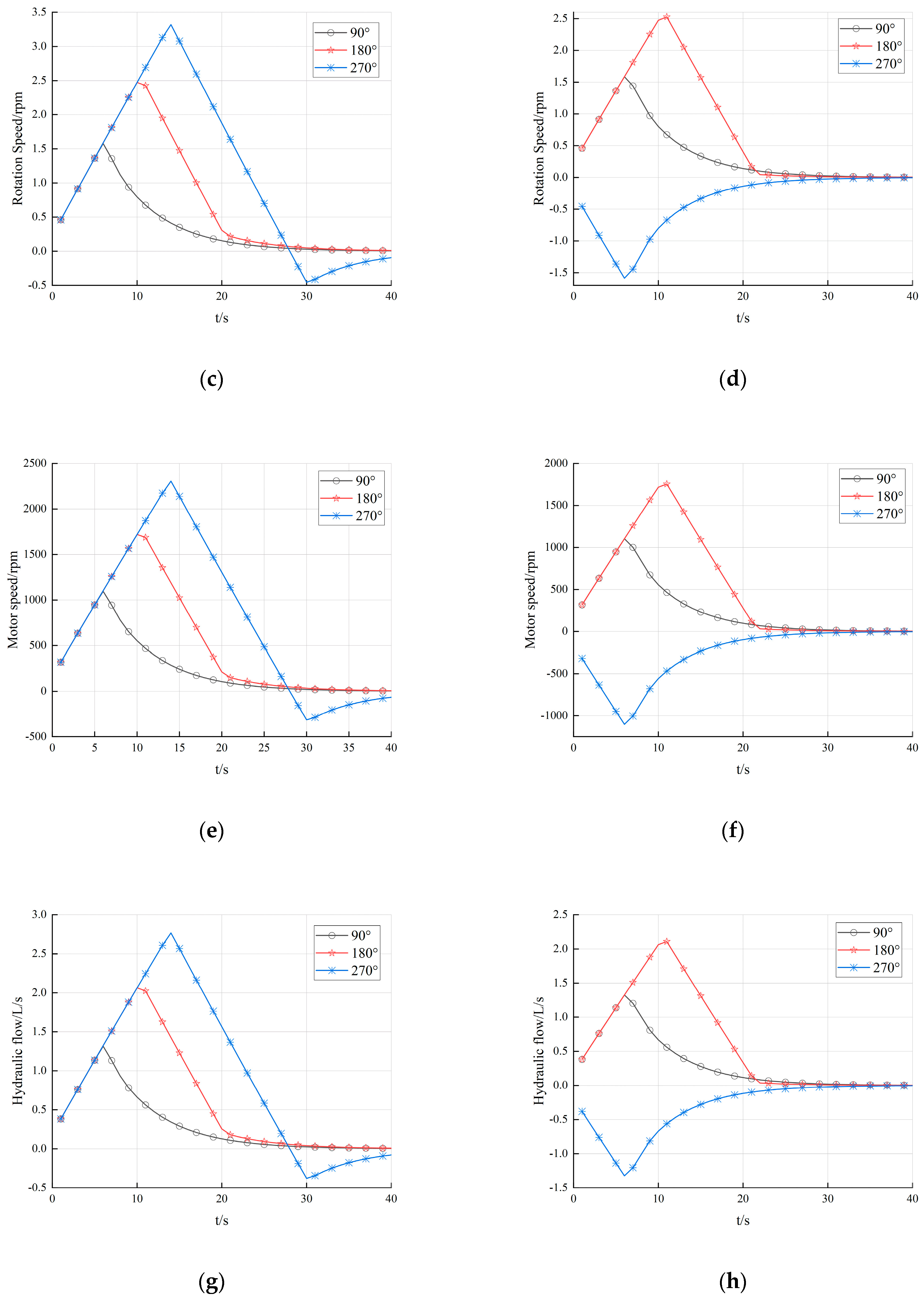
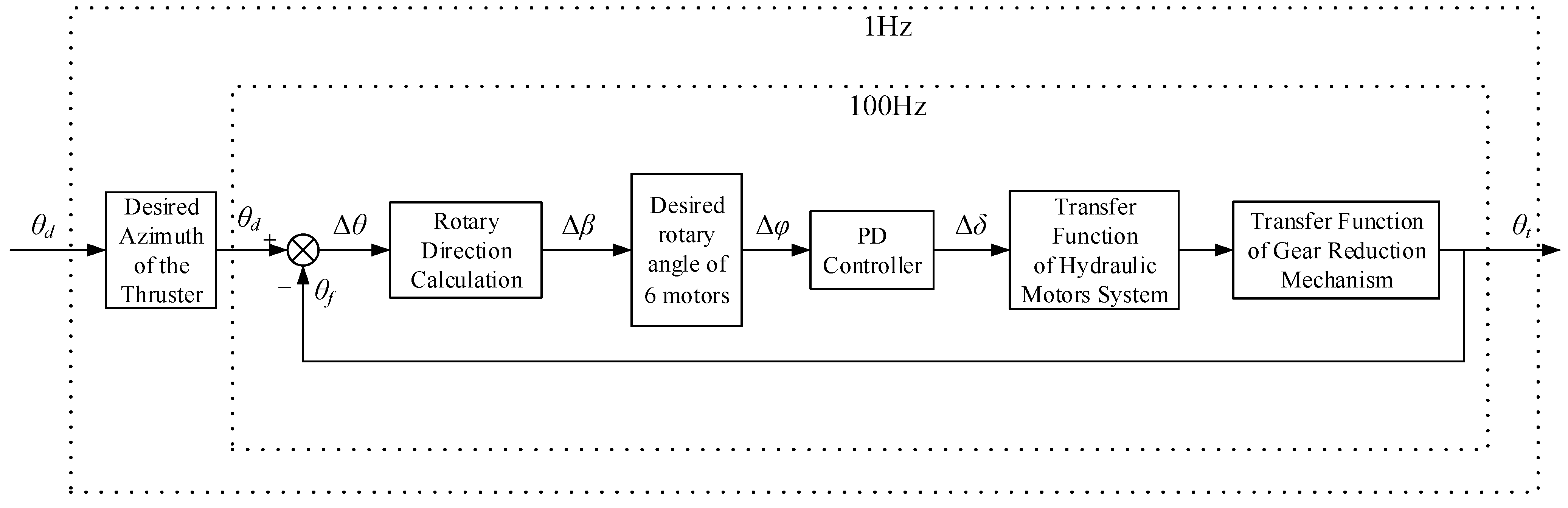
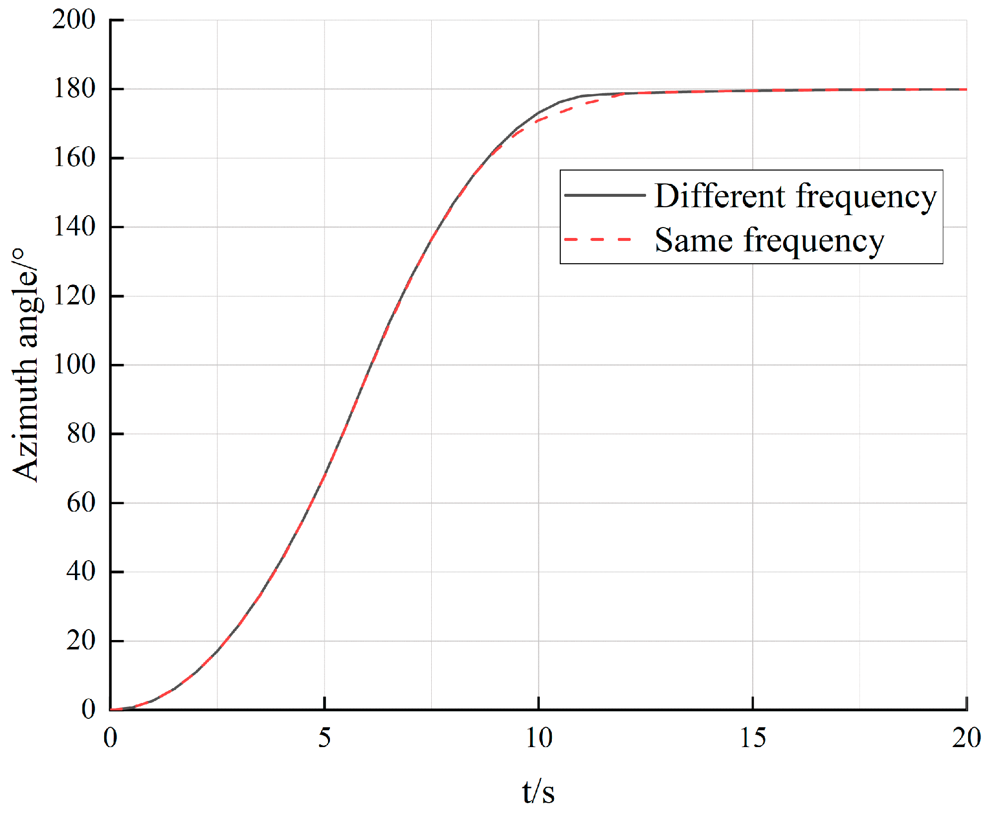
5.3. Simulation of the Inner- and Outer-Loops of the System with Different Control Frequencies

The target azimuth angle of the azimuth thruster is 180°, and two control methods of setting the frequency are simulated: (1) In the inner- and outer-loop synchronous simulation method, the outer-loop control period and inner-loop control period are the same, i.e., T o u t = T i n = 0.01   s . (2) In the inner- and outer-loop asynchronous simulation method, the outer-loop control period is different from the inner-loop control period; i.e., T o u t = 1 and T i n = 0.01   s . The dynamic response of the thruster azimuth is obtained, as shown in Figure 6.
In Figure 6, when using the asynchronous simulation method for the inner- and outer-loops, the stabilization time for the thruster azimuth angle to reach 180° is 12 s, whereas when using the synchronous simulation method for the inner- and outer-loops, the stabilization time for the thruster azimuth angle to reach 180° is 10 s. The difference in the results between the two methods is small, and the dynamic response of the thruster rotation azimuth is basically the same for the two simulation methods.
The results show that the dynamic response of the proposed inner- and outer-loop asynchronous simulation method is basically the same as that of the synchronous simulation method. This result is consistent with the characteristic that the control frequency of the hydraulic system is higher than that of the dynamic positioning in the actual control process of a dynamic positioning ship.
In the design of the dynamic positioning simulation system, the asynchronous simulation method can be used to realize the effective integration of the dynamic positioning control system and hydraulic rotary system, which are two systems with different control frequencies. The response of a real dynamic positioning system can thus be simulated more realistically.

6. Conclusions

The rotation dynamic system of an FS-3510 azimuth vector thruster was modeled and simulated. The main contributions and findings of the work are summarized as follows:
  • A hydraulic rotary dynamic system model and method of simulating the azimuth vector thruster were proposed to reflect the dynamic response of the hydraulic rotary dynamic system of the azimuth thruster.
  • An optimal strategy for controlling the direction of rotation of the azimuth vector thruster was proposed. The azimuth output via the thrust allocation module of the dynamic positioning system was introduced into the simulation model as the target azimuth. By judging the deviation between the target azimuth and the real azimuth, the rotation angle and direction of the azimuth thruster were obtained. The range of the rotation angle was reduced from [−2π, 2π] to [−π, π]. Combined with PID control, the swashplate angle controller of the hydraulic pump was designed to simplify the control of the rotation angle and the direction of the azimuth thruster. The control efficiency of the rotary dynamic system of the azimuth thruster was thus improved.
  • A simulation method of an asynchronous control frequency for the joint simulation of the dynamic positioning system and hydraulic rotary system was proposed. There are two frequency control systems in the process of dynamic positioning ship control, and the control frequency of the hydraulic system of a real ship is 100 times that of the dynamic positioning system. The simulation process in this paper sets the dynamic positioning system (outer-loop) to execute every second, and the hydraulic control system (inner-loop) is executed every 0.01 s. This simulation method having a variable step size can simulate two different control frequencies in the dynamic positioning system.
  • The constraint conditions of the thruster rotation rate of the propulsion distribution strategy of the dynamic positioning system were proposed. The maximum rotation rate of the Wärtsilä FS-3510 azimuth vector thruster is less than 3 r/min. It was concluded from the simulation and analysis results for different target azimuth angles that the maximum rotation speed of the azimuth thruster rotation simulation system was 2.5–3.5 r/min. The difference between the two values is reasonable for a mathematical model of the rotary dynamic system, and it meets the requirements of the rotary physical constraint condition (n ≤ 3 r/min) of the thrust allocation method of the dynamic positioning system.

Author Contributions

Conceptualization, R.L. and Z.J.; methodology, R.L. and X.L.; software, R.L. and X.L.; data curation, X.L.; writing—original draft preparation, R.L. and Z.J.; writing—review and editing, X.L. and L.Y.; supervision, L.Y.; project administration, L.Y.; funding acquisition, X.L. All authors have read and agreed to the published version of the manuscript.

Funding

This research was funded by the National Key Research and Development Program of China (grant number: 2018YFC1406000), the National Science and Technology Major Project (grant number: 2016ZX05057020) and the National Natural Science Foundation of China (grant number: 51509046). The APC was funded by the National Key Research and Development Program of China (grant number: 2018YFC1406000).

Data Availability Statement

If you need to obtain data supporting the reported results, you can contact the corresponding author.

Conflicts of Interest

The authors declare no conflict of interest.

References

  1. Bian, X.; Fu, M.; Wang, Y. Ship Dynamic Positioning; Science Press: Beijing, China, 2011; pp. 7–9. [Google Scholar]
  2. Fossen, T. Handbook of Marine Craft Hydrodynamics and Motion Control; Wiley: New York, NY, USA, 2011; pp. 398–411. [Google Scholar]
  3. Ye, B.; Xiong, J.; Wang, Q.; Luo, Y. Design and Implementation of Pseudo-Inverse Thrust Allocation Algorithm for Ship Dynamic Positioning. IEEE Access 2019, 8, 16830–16837. [Google Scholar] [CrossRef]
  4. Yu, Y.; Mei, B.; Xu, G.; Shao, K.; Wang, X. High-power offshore adjustable pitch full-turn propulsion system. Shipbuild. Sci. Technol. 2015, 4, 20–23. [Google Scholar]
  5. Kim, S.; Kim, M. Fuel-Optimal Thrust-Allocation Algorithm Using Penalty Optimization Programing for Dynamic-Positioning-Controlled Offshore Platforms. Energies 2018, 11, 2128. [Google Scholar] [CrossRef]
  6. Fu, M.; Sun, J.; Wang, D. Research on Thrust Allocation of Dynamic Positioning Ship with Cycloidal Propeller. In Proceedings of the 2018 37th Chinese Control Conference (CCC), Wuhan, China, 25–27 July 2018; pp. 620–624. [Google Scholar]
  7. Li, X.; Jiang, S.; Cui, H.; Wang, H. Dynamics analysis of hydraulic thruster with propeller load. J. Huazhong Univ. Sci. Technol. (Nat. Sci. Ed.) 2017, 45, 23–28. [Google Scholar]
  8. Arditti, F.; Cozijn, H.; Daalen, E.; Tannuri, E. Robust thrust allocation algorithm considering hydrodynamic interactions and actuator physical limitations. J. Mar. Sci. Technol. 2019, 24, 1057–1070. [Google Scholar] [CrossRef]
  9. Gao, D.; Wang, X.; Wang, T.; Wang, Y.; Xu, X. Optimal Thrust Allocation Strategy of Electric Propulsion Ship Based on Improved Non-Dominated Sorting Genetic Algorithm II. IEEE Access 2019, 7, 135247–135255. [Google Scholar] [CrossRef]
  10. Qiu, E. Design of underwater rotary propeller dynamic response simulation software. Ship Sci. Technol. 2019, 41, 91–93. [Google Scholar]
  11. Koschorrek, P.; Palm, M.; Jeinsch, T. A dynamic allocation strategy for voith Schneider propeller. IFAC-Pap. 2017, 50, 1127–1132. [Google Scholar]
  12. Tang, Z.; He, H.; Wang, L.; Wang, X. An optimal thrust allocation algorithm with bivariate thrust efficiency function considering hydrodynamic interactions. J. Mar. Sci. Technol. 2022, 27, 52–66. [Google Scholar] [CrossRef]
  13. Xia, G.; Sun, P.; Xia, B. Research on Thrust Allocation Optimization with Main Propeller-rudder Based on Improved Genetic Algorithm. In Proceedings of the 2019 IEEE International Conference on Mechatronics and Automation (ICMA), Tianjin, China, 4–7 August 2019; pp. 2019–2024. [Google Scholar]
  14. Ding, F.; Yu, Q.; Xu, Y.; Wang, Y. A Novel Thrust Allocation Method Based on Improved Genetic Algorithm. In Proceedings of the 2019 Chinese Control Conference (CCC), Guangzhou, China, 27–30 July 2019; pp. 1869–1874. [Google Scholar]
  15. Chen, Y.; Xu, H.; Feng, H.; Yu, W.; Li, T. Adaptive Group Bias Thrust Allocation Algorithm Based on Energy Optimization. In Proceedings of the 29th International Ocean and Polar Engineering Conference, Honolulu, HI, USA, 16–21 June 2019; pp. 19–171. [Google Scholar]
  16. Hu, X.; Du, J. Robust nonlinear control design for dynamic positioning of marine vessels with thruster system dynamics. Nonlinear Dyn. 2018, 94, 365–376. [Google Scholar] [CrossRef]
  17. Tuo, Y.; Zhou, X.; Huang, W. Thrust allocation based on improved global artificial fish swarm algorithm for the dynamic positioning system of vessels. In Proceedings of the 2021 6th International Conference on Automation, Control and Robotics Engineering (CACRE), Dalian, China, 15–17 July 2021; pp. 560–566. [Google Scholar]
  18. Tang, Z.; Wang, L.; Yi, F.; He, H. An Optimized Thrust Allocation Algorithm for Dynamic Positioning System Based on RBF Neural Network. In Proceedings of the ASME 2020 39th International Conference on Ocean, Offshore and Arctic Engineering, Virtual, Online, 3–7 August 2020; Volume 6A. [Google Scholar]
  19. Haseltalab, A.; Garofano, V.; Pampus, M.; Negenborn, R. Model Predictive Trajectory Tracking Control and Thrust Allocation for Autonomous Vessels. IFAC-Pap. 2020, 53, 14532–14538. [Google Scholar] [CrossRef]
  20. Skulstad, R.; Li, G.; Zhang, H.; Fossen, T. A Neural Network Approach to Control Allocation of Ships for Dynamic Positioning. IFAC-Pap. 2018, 51, 128–133. [Google Scholar] [CrossRef]
  21. Zhao, B.; Xia, G. Recursive-Biased-Generalized-Inverse Method for Thrust Allocation for Dynamic Positioning Vessels with Non-Rotatable Thrusters and Force Constraints. IOP Conf. Ser. Mater. Sci. Eng. 2020, 853, 012033. [Google Scholar] [CrossRef]
  22. Vu, M.T.; Le, T.; Thanh, H.L.N.N.; Huynh, T.; Van, M.; Hoang, Q.; Do, T.D. Robust Position Control of an Over-Actuated Underwater Vehicle under Model Uncertainties and Ocean Current Effects Using Dynamic Sliding Mode Surface and Optimal Allocation Control. Sensors 2021, 21, 747. [Google Scholar] [CrossRef] [PubMed]
  23. Li, X.; Yuan, L.; Zan, Y. Simulation Method of Hydraulic Slewing Dynamics Control System of Azimuth Vector Thruster. China Patent 07194106B, 2019. [Google Scholar]
  24. Liang, L. Hydraulic Transmission and Electro-Hydraulic Servo System; Harbin Engineering University Press: Harbin, China, 2005; pp. 170–198. [Google Scholar]
Figure 1. Main components of the azimuth thruster [23]: (1) shafting assembly, (2) a hydraulic rotation mechanism (3) rotation sleeve, (4) cabin bottom plate, (5) shroud, (6) paddle and (7) propulsion pod.
Jmse 11 00399 g001
Figure 2. Hydraulic rotary control system [23].
Jmse 11 00399 g002
Figure 3. Schematic diagram of different frequency control systems.
Jmse 11 00399 g003
Figure 4. Schematic diagram of the hydraulic rotary dynamic control system.
Jmse 11 00399 g004
Figure 5. Simulation results. (a) Azimuth response without rotary direction optimization; (b) azimuth response with rotary direction optimization; (c) rotary rate response without rotary direction optimization; (d) rotary rate response with rotary direction optimization; (e) hydraulic motor speed response without rotary direction optimization; (f) hydraulic motor speed response with rotary direction optimization; (g) hydraulic flow response without rotary direction optimization; (h) hydraulic flow response with rotary direction optimization; (i) hydraulic pressure response without rotary direction optimization; (j) output torque response with rotary direction optimization.
Jmse 11 00399 g005aJmse 11 00399 g005bJmse 11 00399 g005c
Figure 6. Simulation results for the same frequency and different frequencies of the inner- and outer-loops.
Jmse 11 00399 g006
Table 1. Technical parameters of the pump-controlled hydraulic-motor-driven reduction gear system.
SymbolParameterNumerical Value
DMDisplacement of hydraulic motor/m31.20 × 10−5
JMoment of inertia of propellers and rotary mechanisms/(kg·m2)1.00 × 104
kTotal reduction ratio6.95 × 102
CtTotal leakage coefficient2.00 × 10−12
V0Total volume/m30.38 × 10−3
βeEffective bulk modulus of oil/Pa7.00 × 108
BMViscous damping coefficient/(N·m·s·rad−1)0.01
DpDisplacement of variable pump/(m3·rad−1)2.87 × 10−5
Disclaimer/Publisher’s Note: The statements, opinions and data contained in all publications are solely those of the individual author(s) and contributor(s) and not of MDPI and/or the editor(s). MDPI and/or the editor(s) disclaim responsibility for any injury to people or property resulting from any ideas, methods, instructions or products referred to in the content.

