
Drill Cuttings Disposal Efficiency in Offshore Oil Drilling


Abstract
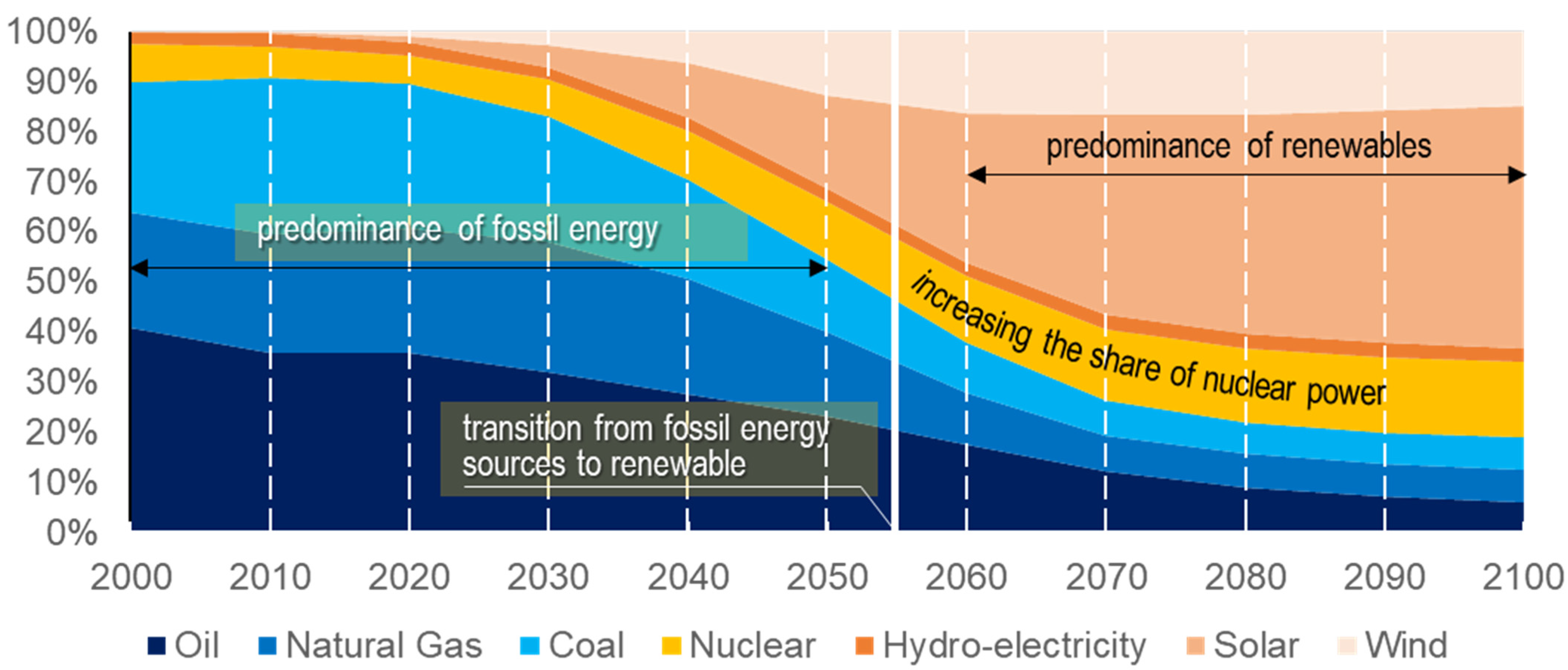
:1. Introduction
- To conduct a review of the literature regarding drilling waste disposal options to identify the most effective ones in offshore exploration and production and assess recycling prospects;
- To determine the initial data and methodology for calculating drill cuttings volume and associated transportation costs;
- To compare the results and identify the advantages and disadvantages of the drilling waste disposal methods under analysis;
- To assess the prospects of using these methods in offshore drilling in Russia.
2. Literature Review
2.1. Current Situation
2.2. Options for Drilling Waste Disposal
3. Materials and Methods
- Geological: mineralogical composition of rocks, fluid properties, reservoir conditions of occurrence (reservoir pressure, abnormally low or abnormally high, presupposes the basis the drilling fluid will be selected on), the presence of layers suitable for drilling an absorbing well;
- Geographical: the main condition is the distance from the deposit to the shore;
- Ecological: proximity of fragile ecosystems and specially protected areas;
- Legislative: restrictions on environmental standards are prescribed in the regulatory framework of each state;
- Climatic conditions: ice conditions, duration of the drilling slot period.
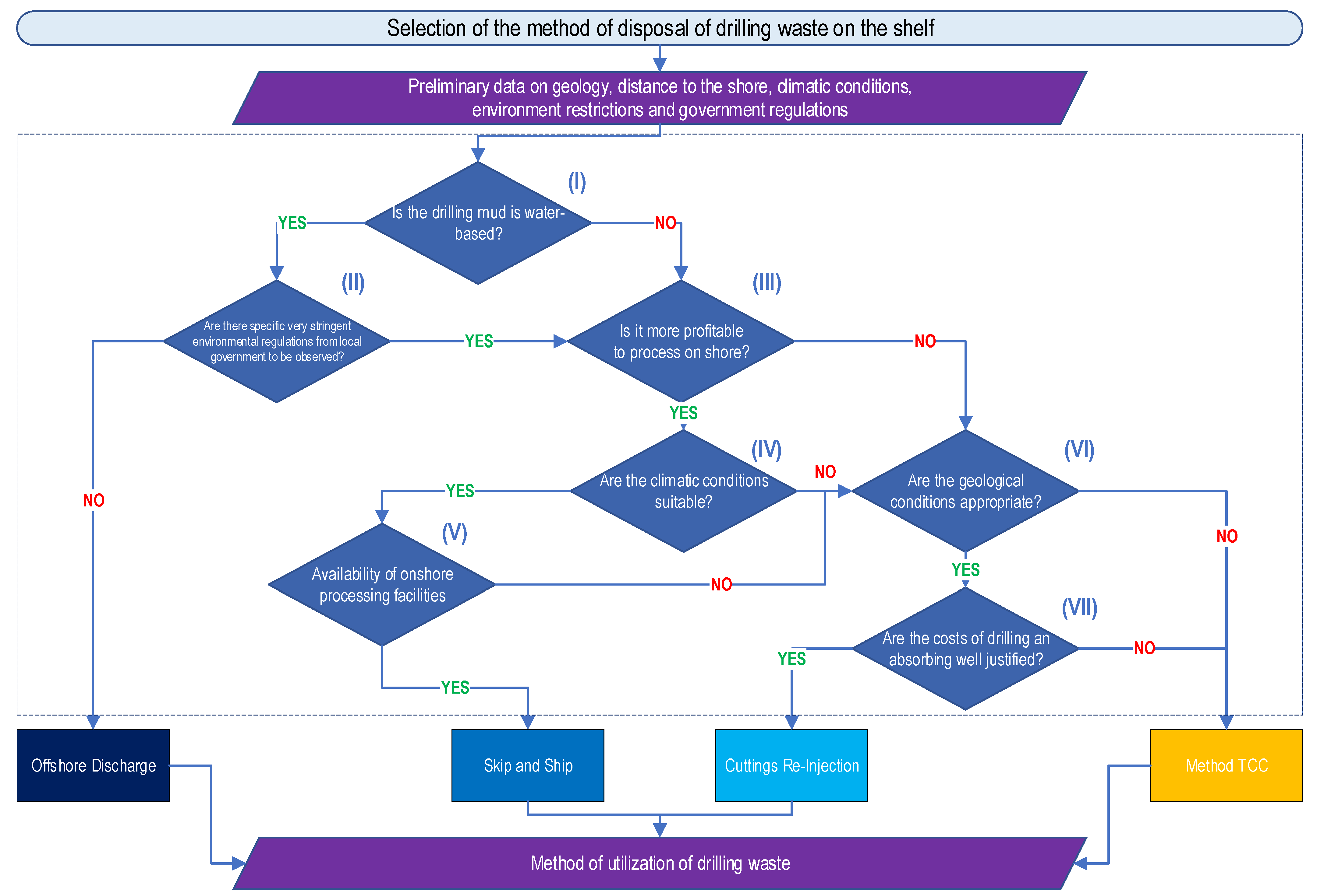
- (I) On what basis will be the drilling mud? According to the source [37], there are three types of drilling fluids: oil-based, water-based, and pneumatic. The water-based solution affects the environment to a lesser extent, and after the Cuttings Dryer System, it is possible to discharge the resulting waste into the waters.
- (II) Are there very stringent, specific environmental regulations from the local government to be observed? In any case, in order to discharge drilling waste into the sea, it is required to purify them to environmental standards adopted by the state in environmental protection regulations. For instance, different countries use their own specific requirement or technical specification related to drilling discharge and waste management [20].
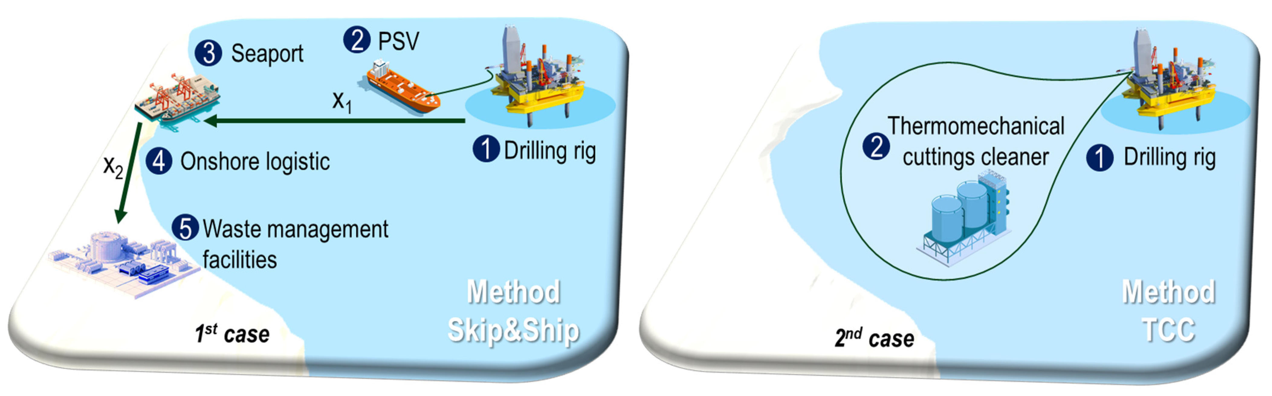
- (III) Is it cost-effective to process waste onshore? The Skip and Ship method is well-known and quite simple to implement compared to other methods of waste disposal on the shelf [8].
- (IV) Are the climatic conditions suitable? The Skip and Ship method is subject to restrictions under difficult climatic conditions; for example, if the deposit is located in Arctic waters, then it is necessary to take into account the ice conditions.
- (V) Are there any waste processing facilities nearby? After transporting drilling waste ashore, it is required to deliver them to the nearest processing point. In the absence of such structures, the method is rejected.
- (VI) Are the geological conditions appropriate? If there is an absorbing reservoir for drilling a well for drilling waste, it is possible to avoid the purchase of expensive equipment for its processing, and waste-free drilling also occurs since the volumes of waste are injected into the well and do not affect the environment.
- (VII) Are the costs of drilling an absorbing well justified? Drilling an absorbing well is an expensive process. This type of disposal will be justified in the case of production drilling and not exploration (during which one or, less often, two wells are drilled).

| Platform Supply Vessel | Capacity, m3 | Discharge Rate, m3/h | Installed Power, kW | Vessel Speed, km/h | Specific Fuel Consumption, kg/kWh |
|---|---|---|---|---|---|
| Baltic | 257 | 159 | 625 | 14.8 | 0.15 |
| Cabral | 441 | 228 | 2811 | 22.2 | 0.25 |
| Resolute | 798 | 136 | 2850 | 17.2 | 0.26 |
| Defiance | 970 | 75 | 3945 | 18.5 | 0.24 |
| Demerara | 1085 | 75 | 4873 | 15.9 | 0.18 |
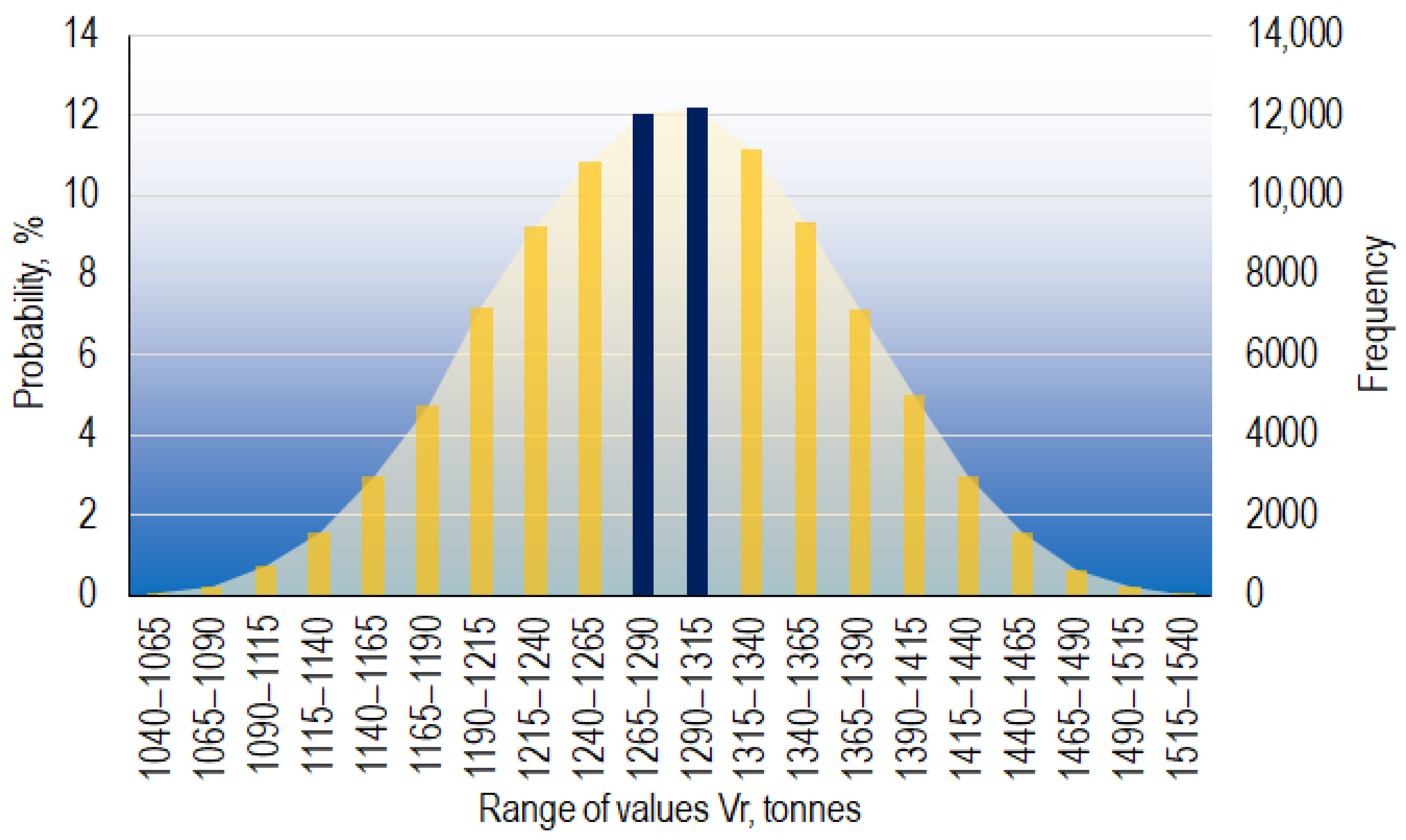
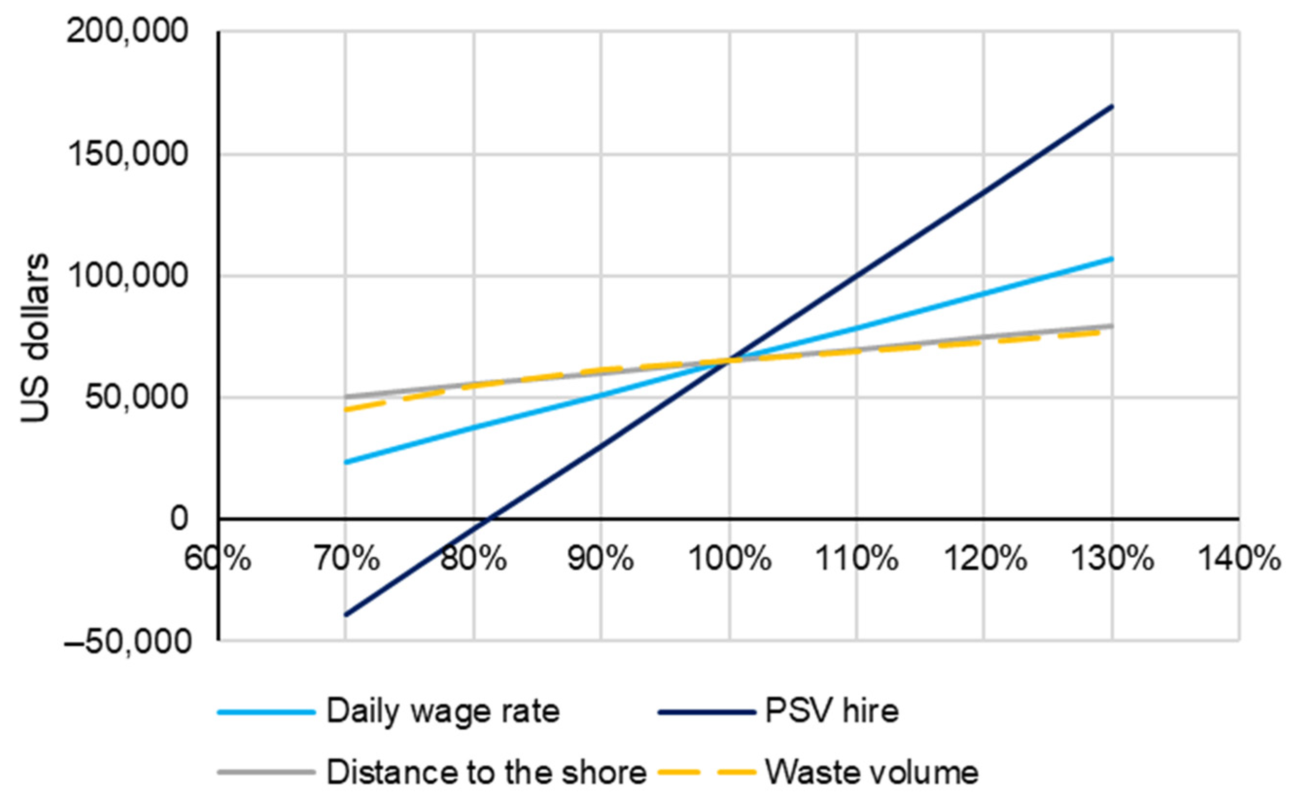
4. Results
5. Discussion
6. Conclusions
Author Contributions
Funding
Institutional Review Board Statement
Informed Consent Statement
Data Availability Statement
Conflicts of Interest
References
- Griggs, D.; Stafford-Smith, M.; Gaffney, O.; Rockström, J.; Öhman, M.C.; Shyamsundar, P.; Steffen, W.; Glaser, G.; Kanie, N.; Noble, I. Sustainable Development Goals for People and Planet. Nature 2013, 495, 305–307. [Google Scholar] [CrossRef]
- Jain, N.K.; Panda, A.; Choudhary, P. Institutional Pressures and Circular Economy Performance: The Role of Environmental Management System and Organizational Flexibility in Oil and Gas Sector. Bus Strategy Environ. 2020, 29, 3509–3525. [Google Scholar] [CrossRef]
- Ilinova, A.; Romasheva, N.; Stroykov, G. Prospects and Social Effects of Carbon Dioxide Sequestration and Utilization Projects. J. Min. Inst. 2020, 244, 493–502. [Google Scholar] [CrossRef]
- Dvoynikov, M.; Buslaev, G.; Kunshin, A.; Sidorov, D.; Kraslawski, A.; Budovskaya, M. New Concepts of Hydrogen Production and Storage in Arctic Region. Resources 2021, 10, 3. [Google Scholar] [CrossRef]
- Litvinenko, V.; Tsvetkov, P.; Dvoynikov, M.; Buslaev, G. Barriers to Implementation of Hydrogen Initiatives in the Context of Global Energy Sustainable Development. J. Min. Inst. 2020, 244, 428–438. [Google Scholar] [CrossRef]
- Tsvetkov, P.; Fedoseev, S. Analysis of Project Organization Specifics in Small-Scale LNG Production. J. Min. Inst. 2021, 246, 678–686. [Google Scholar] [CrossRef]
- Sky Scenario | Shell Global. Available online: https://www.shell.com/energy-and-innovation/the-energy-future/scenarios/shell-scenario-sky.html (accessed on 8 April 2022).
- Kazamias, G.; Zorpas, A.A. Drill Cuttings Waste Management from Oil and Gas Exploitation Industries through End-of-Waste Criteria in the Framework of Circular Economy Strategy. J. Clean. Prod. 2021, 322, 129098. [Google Scholar] [CrossRef]
- Blinova, E.; Ponomarenko, T.; Knysh, V. Analyzing the Concept of Corporate Sustainability in the Context of Sustainable Business Development in the Mining Sector with Elements of Circular Economy. Sustainability 2022, 14, 8163. [Google Scholar] [CrossRef]
- Obzor Nefteservisnogo Rynka Rossii-2021. Available online: https://ru.investinrussia.com/data/files/sectors/russia-oil-gas-survey-2021.pdf (accessed on 19 October 2022).
- Gazpromneft Annual Report 2021. Available online: https://investonic.ru/wp-content/uploads/2022/08/gazprom-annual-report-2021-ru.pdf (accessed on 25 October 2022).
- Tatneft Annual Report 2021. Available online: https://www.tatneft.ru/uploads/publications/62b5b3197d035342141266.pdf (accessed on 25 October 2022).
- Surgutneftegas Annual Report 2020. Available online: https://www.surgutneftegas.ru/investors/essential_information/reporting/ (accessed on 25 October 2022).
- Lukoil Annual Report 2021. Available online: https://lukoil.ru/FileSystem/9/587033.pdf (accessed on 25 October 2022).
- Slavneft Annual Report 2020. Available online: https://www.slavneft.ru/_upload/doc/Annual_Report_2020_1.pdf (accessed on 25 October 2022).
- Rosneft Annual Report 2021. Available online: https://www.rosneft.com/upload/site2/document_file/a_report_2021_eng.pdf (accessed on 25 October 2022).
- Reza Hassan, K.; Melnik, D. Global Trends in Well Drilling and Completion Market: Rystad Energy’s Outlook by 2025—ROGTEC. Available online: https://www.rogtecmagazine.com/global-trends-in-well-drilling-and-completion-market-rystad-energys-outlook-by-2025/ (accessed on 2 May 2022).
- Informacionnyj Byulleten’. Available online: https://vygon.consulting/services/bulletin/vygon_consulting-thomson_reuters/ (accessed on 3 May 2022).
- Siddique, S.; Leung, P.S.; Njuguna, J. Drilling Oil-Based Mud Waste as a Resource for Raw Materials: A Case Study on Clays Reclamation and Their Application as Fillers in Polyamide 6 Composites. Upstream Oil Gas Technol. 2021, 7, 100036. [Google Scholar] [CrossRef]
- Ismail, A.R.; Alias, A.H.; Sulaiman, W.R.W.; Jaafar, M.Z.; Ismail, I. Drilling Fluid Waste Management in Drilling for Oil and Gas Wells. Chem. Eng. Trans. 2017, 56, 1351–1356. [Google Scholar] [CrossRef]
- Korshunov, G.; Eremeeva, A.; Drebenstedt, C. Justification of the Use of a Vegetal Additive to Diesel Fuel as a Method of Protecting Underground Personnel of Coal Mines from the Impact of Harmful Emissions of Diesel-Hydraulic Locomotives. J. Min. Inst. 2021, 247, 39–47. [Google Scholar] [CrossRef]
- Gendler, S.G.; Prokhorova, E.A. Assessment of the Cumulative Impact of Occupational Injuries and Diseases on the State of Labor Protection in the Coal Industry. Min. Inf. Anal. Bull. 2022, 105–116. [Google Scholar] [CrossRef]
- Rana, S. Facts and Data on Environmental Risks—Oil and Gas Drilling Operations. In Proceedings of the All Days, Calgary, AB, Canada, 20–23 October 2008; SPE: London, UK. [Google Scholar]
- Garland, E.; Kerr, J.M.; Mundy, K.J.; Mason, M.J.; Young, S.; Pegors, S.R.; Sedlock, E.; Barrett, J.; Campbell, J.; Eygun, C. OGP Exploration and Production Waste Management Guidelines. In Proceedings of the All Days, Nice, France, 15 April 2008; SPE: London, UK, 2008. [Google Scholar]
- Ball, A.S.; Stewart, R.J.; Schliephake, K. A Review of the Current Options for the Treatment and Safe Disposal of Drill Cuttings. Waste Manag. Res. J. A Sustain. Circ. Econ. 2012, 30, 457–473. [Google Scholar] [CrossRef] [PubMed]
- Darajah, M.H.; Karundeng, I.; Setiati, R.; Wastu, A.R.R. Drilling Waste Management Using Zero Discharge Technology with Drill Cutting Re-Injection (DCRI) Method for Environmental Preservation. IOP Conf Ser Earth Env. Sci 2021, 802, 012046. [Google Scholar] [CrossRef]
- Reis, J.C. Remediation of Contaminated Sites. In Environmental Control in Petroleum Engineering; Elsevier: Amsterdam, The Netherlands, 1996; pp. 216–229. [Google Scholar]
- Fedorov, G.B.; Dudchenko, O.L.; Kurenkov, D.S. Development of Vibroacoustic Module for Fine Filtration of Drilling Muds. J. Min. Inst. 2018, 234, 647–651. [Google Scholar] [CrossRef]
- Kirkness, A.; Garrick, D. Treatment of Nonaqueous-Fluid-Contaminated Drill Cuttings—Raising Environmental and Safety Standards. In Proceedings of the All Days, Orlando, FL, USA, 4 March 2008; SPE: London, UK, 2008. [Google Scholar]
- de Almeida, P.C.; Araújo, O.d.Q.F.; de Medeiros, J.L. Managing Offshore Drill Cuttings Waste for Improved Sustainability. J. Clean Prod. 2017, 165, 143–156. [Google Scholar] [CrossRef]
- Kogbara, R.B.; Badom, B.K.; Ayotamuno, J.M. Tolerance and Phytoremediation Potential of Four Tropical Grass Species to Land-Applied Drill Cuttings. Int. J. Phytoremediation 2018, 20, 1446–1455. [Google Scholar] [CrossRef]
- Petri, I.; Pereira, M.S.; dos Santos, J.M.; Duarte, C.R.; Ataíde, C.H.; Panisset, C.M. de Á. Microwave Remediation of Oil Well Drill Cuttings. J. Pet Sci. Eng. 2015, 134, 23–29. [Google Scholar] [CrossRef]
- Chen, Z.; Chen, Z.; Yin, F.; Wang, G.; Chen, H.; He, C.; Xu, Y. Supercritical Water Oxidation of Oil-Based Drill Cuttings. J. Hazard Mater. 2017, 332, 205–213. [Google Scholar] [CrossRef]
- Wasiuddin, N.M.; Ali, N.; Islam, M.R. Use of Offshore Drilling Waste in Hot Mix Asphalt (HMA) Concrete as Aggregate Replacement. In Proceedings of the Engineering Technology Conference on Energy, Parts A and B, Houston, TX, USA, 1 January 2002; ASMEDC: Houston, TX, USA, 2002; Volume 1, pp. 451–458. [Google Scholar]
- Foroutan, M.; Hassan, M.M.; Desrosiers, N.; Rupnow, T. Evaluation of the Reuse and Recycling of Drill Cuttings in Concrete Applications. Constr. Build Mater. 2018, 164, 400–409. [Google Scholar] [CrossRef]
- Vlasov, A.S.; Pugin, K.G.; Surkov, A.A. Geoecological Assessment of the Technology for Using Drilling Waste in the Composition of Asphalt-Concrete. Neft. Khozyaystvo Oil Ind. 2020, 2020, 139–142. [Google Scholar] [CrossRef]
- Kalisz, S.; Kibort, K.; Mioduska, J.; Lieder, M.; Małachowska, A. Waste Management in the Mining Industry of Metals Ores, Coal, Oil and Natural Gas—A Review. J Env. Manag. 2022, 304, 114239. [Google Scholar] [CrossRef]
- Tikhonov, A.S.; Kovalev, A.v. Analysis of Oil and Gas Well Casing Designs in Order to Identify Promising Areas for Further Research. Bull. Tomsk Polytech. Univ. Geo Assets Eng. 2022, 333, 126–143. [Google Scholar] [CrossRef]
- Suleimanov, A.B.; Kuliev, R.P.; Sarkisov, E.I.; Karapetov, K.A. Ekspluataciya Morskih Neftegazovyh Mestorozhdenij; Nedra: Moskva, Russia, 1986. [Google Scholar]
- Tekhnika i Tekhnologiya Cementirovaniya Skvazhin. Available online: https://buriloff.ru/raznoe/tehnika-i-tehnologiya-cementirovaniya-skvazhin.html (accessed on 30 December 2022).
- Borthen, T.; Loennechen, H.; Fagerholt, K.; Wang, X.; Vidal, T. Bi-Objective Offshore Supply Vessel Planning with Costs and Persistence Objectives. Comput. Oper. Res. 2019, 111, 285–296. [Google Scholar] [CrossRef]
- Ulsrud, K.P.; Vandvik, A.H.; Ormevik, A.B.; Fagerholt, K.; Meisel, F. A Time-Dependent Vessel Routing Problem with Speed Optimization. Eur. J. Oper. Res. 2022, 303, 891–907. [Google Scholar] [CrossRef]
- Platform Supply Vessels | SEACOR Marine. Available online: https://seacormarine.com/fleet/platform-supply-vessels/ (accessed on 26 May 2022).
- Počuča, M. Methodology of Day-To-Day Ship Costs Assessment. Promet Traffic Transp. 2006, 18, 337–345. [Google Scholar]
- James, R.W.; Rørvik, B. Total Energy Consumption: A Comparative Case Study of Two Alternative North Sea Cuttings Handling Processes Associated with the Use of Oil Based Drilling Fluids. In Proceedings of the All Days, Kuala Lumpur, Malaysia, 20 March 2002; SPE: London, UK, 2002. [Google Scholar]
- Phillips, L.; Morris, A.; Innes, G.; Clark, A.; Hinden, P.-M. Drilling Waste Management—Solutions That Optimise Drilling, Reduce Well Cost and Improve Environmental Performance. In Proceedings of the Day 2 Tue, Abu Dhabi, United Arab Emirates, 13 November 2018; SPE: London, UK, 2018. [Google Scholar]
- Upstream Oil & Gas Industry Reports | Wood Mackenzie. Available online: https://www.woodmac.com/store/industry-sector/upstream-oil-and-gas/ (accessed on 29 May 2022).
- Mitusova, T.N.; Kondrasheva, N.K.; Lobashova, M.M.; Ershov, M.A.; Rudko, V.A.; Titarenko, M.A. Determination and Improvement of Stability of High-Viscosity Marine Fuels. Chem. Technol. Fuels Oils 2018, 53, 842–845. [Google Scholar] [CrossRef]
- Indeksy Cen Sudovogo Topliva v Portah SPbMTSB. Available online: https://spimex.com/markets/oil_products/indexes/harbor/ (accessed on 31 May 2022).
- Ob Utverzhdenii Federal’nyh Norm i Pravil v Oblasti Promyshlennoj Bezopasnosti “Pravila Bezopasnosti v Neftyanoj i Gazovoj Promyshlennosti” Ot 15 Dekabrya 2020—Docs.Cntd.Ru. Available online: https://docs.cntd.ru/document/573230594 (accessed on 29 May 2022).
- Dmitrieva, D.; Cherepovitsyna, A.; Stroykov, G.; Solovyova, V. Strategic Sustainability of Offshore Arctic Oil and Gas Projects: Definition, Principles, and Conceptual Framework. J. Mar. Sci. Eng. 2021, 10, 23. [Google Scholar] [CrossRef]
- Kirsanova, N.Y.; Lenkovets, O.M. Assessment of Accountability in State Regulation of Arctic Zone of the Russian Federation in Current Institutional Environment. Sev. I Rynok Form. Ekon. Porad. 2022, 75, 47–57. [Google Scholar] [CrossRef]
- Cherepovitsyn, A.; Tsvetkova, A.; Komendantova, N. Approaches to Assessing the Strategic Sustainability of High-Risk Offshore Oil and Gas Projects. J. Mar. Sci. Eng. 2020, 8, 995. [Google Scholar] [CrossRef]
- Teslya, A.B.; Zaychenko, I.M.; Hasheva, Z.M. Development of the Concept for the Strategic Development of the Far North Regions on the Basis of Formulation of a System of Balanced Indicators under the Conditions of Digital Transformation of Socio-Economic Processes. Sev. I Rynok Form. Ekon. Porad. 2022, 25, 58–68. [Google Scholar] [CrossRef]
- Stroykov, G.A.; Babyr, N.V.; Ilin, I.V.; Marchenko, R.S. System of Comprehensive Assessment of Project Risks in the Energy Industry. Int. J. Eng. 2021, 34, 1778–1784. [Google Scholar] [CrossRef]
- Seafarers’ Salaries: Scale by the Maritime-Zone.Com—MZ Blog. Available online: https://maritime-zone.com/en/news/view/seafarers-salaries-scale-by-the-maritime-zone-com (accessed on 27 October 2022).
- Novikov, S.V. Transport i Logistika v Arktike. Al’manah 2015. Vypusk 1; Tekhnosfera: Moskva, Russia, 2015; ISBN 978-5-94836-408-7. [Google Scholar]
- Njuguna, J.; Siddique, S.; Bakah Kwroffie, L.; Piromrat, S.; Addae-Afoakwa, K.; Ekeh-Adegbotolu, U.; Oluyemi, G.; Yates, K.; Kumar Mishra, A.; Moller, L. The Fate of Waste Drilling Fluids from Oil and Gas Industry Activities in the Exploration and Production Operations. Waste Manag. 2022, 139, 362–380. [Google Scholar] [CrossRef] [PubMed]
- Ponomarenko, T.; Marin, E.; Galevskiy, S. Economic Evaluation of Oil and Gas Projects: Justification of Engineering Solutions in the Implementation of Field Development Projects. Energies 2022, 15, 3103. [Google Scholar] [CrossRef]
- Dyachenko, G.P.; Arslanbekov, A.R.; Dedovetc, S.A.; Ushakov, S.N. Vnedrenie Tekhnologii Pererabotki Burovyh Shlamov. Ekol. Proizv. 2009, 8, 64–68. [Google Scholar]
- Caenn, R.; Darley†, H.C.H.; Gray†, G.R. Drilling and Drilling Fluids Waste Management. In Composition and Properties of Drilling and Completion Fluids; Elsevier: Amsterdam, The Netherlands, 2017; pp. 597–636. [Google Scholar]
- Chanysheva, A.; Ilinova, A. The Future of Russian Arctic Oil and Gas Projects: Problems of Assessing the Prospects. J. Mar. Sci. Eng. 2021, 9, 528. [Google Scholar] [CrossRef]
- Samylovskaya, E.; Makhovikov, A.; Lutonin, A.; Medvedev, D.; Kudryavtseva, R.-E. Digital Technologies in Arctic Oil and Gas Resources Extraction: Global Trends and Russian Experience. Resources 2022, 11, 29. [Google Scholar] [CrossRef]
- Syas’ko, V.; Shikhov, A. Assessing the State of Structural Foundations in Permafrost Regions by Means of Acoustic Testing. Appl. Sci. 2022, 12, 2364. [Google Scholar] [CrossRef]
- Stishov, M.S.; Dudley, N. Ohranyaemye Prirodnye Territorii Rossijskoj Federacii i Ih Kategorii; WWF: Gland, Switzerland, 2018; ISBN 978-5-6041734-7-3. [Google Scholar]


| Casing String | Drill Bit Diameter, mm | Casing Collar Diameter, mm | Outside Casing Diameter, mm |
|---|---|---|---|
| Conductor | 914.0 | 804.0 | 762.0 |
| Surface casing | 660.0 | 533.4 | 508.0 |
| 1st intermediate casing | 444.5 | 365.1 | 339.7 |
| 2nd intermediate casing | 295.3 | 269.9 | 244.5 |
| Production casing | 215.9 | 194.5 | 177.8 |
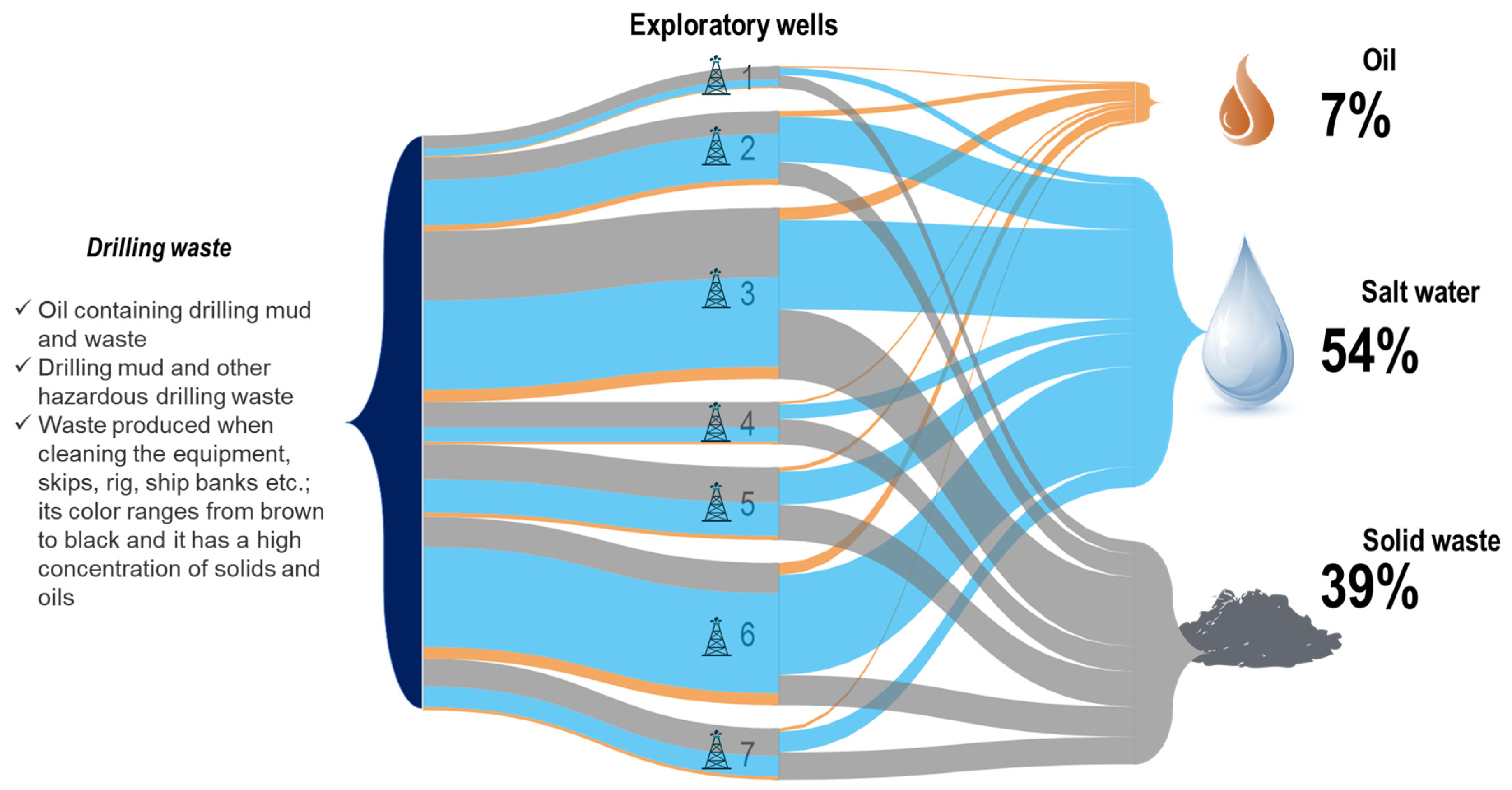
| Field | Depth of Exploratory Wells, m | Distance from the Shore, km | Depth of Sea Level, m | |||
|---|---|---|---|---|---|---|
| from | to | from | to | from | to | |
| Prirazlomnoye | 2412 | 4495 | 60 | 20 | ||
| Pobeda | 2350 | >500 | 1 | 335 | ||
| Neptun, Triton | 2700 | 3000 | 30 | 55 | 62 | 80 |
| Shtokmanovskoye | 2484 | 3153 | 550 | 300 | 350 | |
| Vladimir Filanovsky | 1650 | 2600 | 10 | 100 | 120 | |
| PSV | Quantity of Shipments | Total Discharge Time, h | Ship’s Travel Time, h | Fuel Volume, Tones | Fuel Costs, USD | Personnel Costs, USD | Total, USD |
|---|---|---|---|---|---|---|---|
| Baltic | 5 | 8.0 | 19.0 | 8.2 | 6751 | 174,510 | 181,261 |
| Caspian | 3 | 5.6 | 12.7 | 26.1 | 18,078 | 110,843 | 128,921 |
| Resolute | 2 | 9.3 | 16.4 | 26.5 | 18,354 | 108,755 | 127,109 |
| Defiance | 2 | 16.9 | 15.2 | 38.1 | 26,414 | 116,411 | 142,825 |
| Demerara | 2 | 16.9 | 17.7 | 39.0 | 27,029 | 119,352 | 146,381 |
| Cost Item | Skip and Ship, USD | TCC, USD | Source |
|---|---|---|---|
| Construction and installation work | - | 166,087 | [46] |
| Equipment costs | - | 332,173 | [46] |
| Offshore transportation costs | eliminated | ||
| Fuel | 19,325 | - | calculated |
| Personnel | 125,974 | - | calculated |
| PSV hire | 316,356 | - | [41] |
| Onshore transportation costs | 145,299 | eliminated | [57] |
| Downtime due to weather (10% of offshore transportation costs) | 46,166 | eliminated | [44] |
| TOTAL | 563,183 | 498,260 |
| Advantages | Disadvantages and Limits |
|---|---|
|
|
| Advantages | Disadvantages and Limits |
|---|---|
|
|
Disclaimer/Publisher’s Note: The statements, opinions and data contained in all publications are solely those of the individual author(s) and contributor(s) and not of MDPI and/or the editor(s). MDPI and/or the editor(s) disclaim responsibility for any injury to people or property resulting from any ideas, methods, instructions or products referred to in the content. |
© 2023 by the authors. Licensee MDPI, Basel, Switzerland. This article is an open access article distributed under the terms and conditions of the Creative Commons Attribution (CC BY) license (https://creativecommons.org/licenses/by/4.0/).
Share and Cite
Cherepovitsyn, A.; Lebedev, A. Drill Cuttings Disposal Efficiency in Offshore Oil Drilling. J. Mar. Sci. Eng. 2023, 11, 317. https://doi.org/10.3390/jmse11020317
Cherepovitsyn A, Lebedev A. Drill Cuttings Disposal Efficiency in Offshore Oil Drilling. Journal of Marine Science and Engineering. 2023; 11(2):317. https://doi.org/10.3390/jmse11020317
Chicago/Turabian StyleCherepovitsyn, Alexey, and Andrey Lebedev. 2023. "Drill Cuttings Disposal Efficiency in Offshore Oil Drilling" Journal of Marine Science and Engineering 11, no. 2: 317. https://doi.org/10.3390/jmse11020317
APA StyleCherepovitsyn, A., & Lebedev, A. (2023). Drill Cuttings Disposal Efficiency in Offshore Oil Drilling. Journal of Marine Science and Engineering, 11(2), 317. https://doi.org/10.3390/jmse11020317