Abstract
The classical wake oscillator model is capable of predicting the vortex-induced vibration response of a cylinder at high mass-damping ratios, but it fails to perform satisfactorily at low mass-damping ratios. A modified wake oscillator model is presented in this paper. The modification method involves analyzing the variation law of the add mass coefficient of the cylinder versus reduced velocity and expressing the reference lift coefficient CL0 as a function of the add mass coefficient. The modified wake oscillator model has been demonstrated to have better accuracy in capturing maximum amplitudes and flow velocity at low mass-damping ratios. However, the modified model at present form is unable to accurately predict the vortex-induced vibration response at high damping ratios. The purpose of this paper is to propose a new modification idea. In order to achieve better results when applying this modification idea to particular objects, it may be necessary to first understand the response law of these kinds of objects.
1. Introduction
Vortex-induced vibration is frequently observed in marine structures, such as risers and pipelines, which is one of the leading causes of fatigue damage [1]. Prediction results for the vortex-induced vibration response will provide important reference information for the design of these structures [2]. CFD-based numerical prediction methods are limited in terms of calculation speed and cost for these large-scale structures [3]. Thus, empirical models are widely used in the current software (such as OrcaFlex) for the prediction of vortex-induced vibrations [4]. Due to the strong nonlinearity of vortex-induced vibration, it is difficult to accurately predict its response under all test conditions by using an empirical model. The relevant empirical model may need to be modified in accordance with the characteristics of a particular structure in order to produce more accurate results.
Structures like marine risers have a relatively low mass damping ratio, which results in a larger vortex-induced vibration amplitude. The conventional empirical model is generally applicable to cases with high mass damping ratios, thus it is usually not suitable for predicting the vibration response of structures with low mass damping ratios, such as risers. There are many kinds of empirical models for predicting vortex-induced vibration such as aerodynamic damping models [5], neural network model [6], etc. Due to its high computational speed, the wake oscillator model is one of the most commonly used empirical models for the prediction of vortex-induced vibration response [7]. The classical wake oscillator model widely used at present is proposed by Facchinetti et al. [8]. In the classical wake oscillator model, the near wake dynamics is defined by the wake oscillator [9], in which a single flow variable is used to model the fluctuating nature of the vortex shedding. The variable is assumed to satisfy a van der Pol equation, thus it has the features of stable, self-sustained, and nearly harmonic oscillation of finite amplitude. This wake oscillator is coupled with the motion equation of a one degree-of-freedom elastically supported rigid structure, namely a structure oscillator. The wake oscillator and structure oscillator are coupled via a coupling term [10,11,12].
Although the classical wake oscillator model has been demonstrated to be good at predicting the vortex-induced vibration response of the cylinder at high mass-damping ratios, it does not perform satisfactorily at low mass-damping ratios, since the parameters of the classical wake oscillator model are determined by fitting the experimental data for high mass-damping ratios [13]. Studies have shown that there are two distinct types of cylinder’s vortex-induced vibration response, depending on whether one has a high or low combined mass-damping parameter (m*ζ) [14]. In the classical high m*ζ case, an ‘initial’ and ‘lower’ amplitude branch are separated by a discontinuous mode transition, whereas in the case of low m*ζ, a further higher-amplitude ‘upper’ branch of response appears, and there exist two mode transitions [14,15]. The frequency response characteristics of these two types of vortex-induced vibration are evidently different in the lock-in regimes. For high m*ζ cases, the frequency ratio (ratio of vibration frequency to the natural frequency of the vibrator) is close to 1 in lock-in regimes [16,17]. However, for low m*ζ cases, the frequency ratio is higher, and may varies with m* [18,19,20]. Therefore, the classical wake oscillator model suitable for the high m*ζ case rarely adequately captures the characteristics of upper branches in the low m*ζ case.
In view of the above issue, many scholars have tried to modify the classical wake oscillator model. Xu et al. [21] modified the classical wake oscillator model by refitting the empirical parameters so that the wake oscillator model would be more accurate in calculating low m*ζ cases. Farshidianfar and Zanganeh [22] proposed a modified wake oscillator model using van der Pol equation for structural oscillations and coupled with the wake oscillator via a velocity coupling term. They claimed that the improved model has higher accuracy than the classical model. Kurushina et al. [23] proposed a high order wake oscillator model for low mass ratio structures based on the van der Pol oscillator, which is able to consider the coupling effect between cross-flow and in-line motions of the structure. Qu and Metrikine [24] modified the high order wake oscillator model by adding a nonlinear wake variable for the in-line motion, in order to improve the calculation accuracy for low mass ratio cases. The above modification methods can be divided into two forms. In the first form, the empirical parameters are re-fitted while keeping the wake oscillator equation unchanged, thus making it suitable for cases with low mass ratios. However, since this modification method does not rely on the physical mechanism, the modified model obtained by this method generally has a limited range of application. In the second form, the low-order model is transformed into the higher-order model. In a higher-order model, more factors can be considered, but the equations are more complex to express. In this type of model, the empirical parameters are more numerous, and the coupling between parameters is more complex, which may increase the output uncertainty and reduce the level of confidence [25].
The above modified wake oscillator models put forward their modification ideas from different perspectives, which can be used for reference when building vortex-induced vibration prediction models for structures with low mass damping ratio such as risers. However, in the above literatures, the modification strategy of added mass and lift coefficient has rarely been discussed. Several studies have demonstrated that modifying added mass plays a crucial role in improving analytical results [26,27], and proved that a consistent interpretation of relevant hydrodynamic parameters, written as functions of reduced velocity, namely the added mass, the fluid damping and the lift force, plays an essential role in improving analytical models of the van der Pol oscillator type [28]. Those studies provide an excellent basis for improving the wake oscillator model, and further research is warranted.
As the change trend of added mass and lift coefficient of vortex-induced vibration is very different in the case of low and high m*ζ, this paper is primarily concerned with proposing a new approach to modifying the parameters of the added mass and reference lift coefficient, as well as verifying its rationality.
2. Classical Wake Oscillator Model
The modified wake oscillator model presented in this paper builds upon the classical wake oscillator model widely used in the literature, which is coupled by an acceleration coupling term [29]. In this section, the classical wake oscillator model is introduced.
2.1. Equations of Wake and Structure Oscillators
Figure 1 shows the vortex-induced vibration of an elastically mounted cylinder coupled with wake oscillators. The cylinder with diameter D is affected by the flow with velocity U, and oscillates transversely. It is therefore possible to express the motion of the cylinder as follows:
where Y is the cylinder’s transverse displacement, k is the stiffness of the cylinder, S is the fluid force, ms is the mass of the cylinder, mf is the added mass, CM is the added mass coefficient, ρ is the density of fluid, D is the cylinder’s diameter, r is the total damping of the system, rs is the damping of the supporting structure, rf is the fluid-added damping, is the fluid-added damping coefficient, ꞷf is the angular frequency of cylinder vibration, St is the Strouhal number, U is the flow velocity, and CL is the fluctuating lift coefficient.
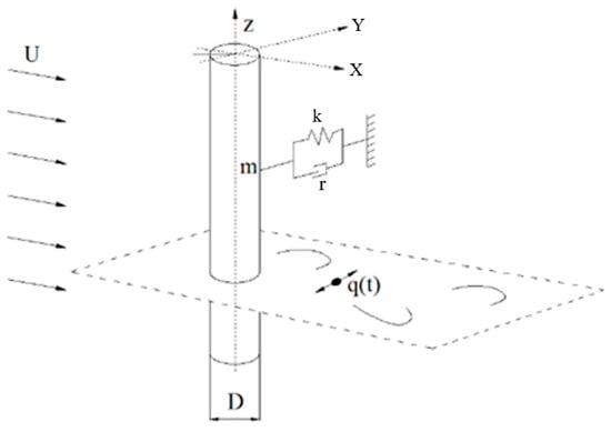
Figure 1.
Model of vortex-induced vibration of elastically mounted cylinder coupled with wake oscillators [8].
In the classical wake oscillator model, the fluctuating characteristics of the wake vortex is modeled by a van der Pol oscillator, which can be expressed as:
where ε and N are empirical parameters, q is the dimensionless wake variable defined by q(t) = 2CL(t)/CL0, where CL0 is the reference lift coefficient.
By combining and nondimensionalizing the equations of structural vibration and fluctuating lift, equations of wake oscillator model can be obtained as:
where ξ = cs/(2msωn) is the structure-reduced damping, cs is the structural damping, ωn = (k/ms)1/2 is the natural circular frequency of the structure, μ = (ms + ma)/ρD2 is the mass ratio, and δ = ωn/ωst is the frequency ratio. The specific derivation can be found in the reference [8].
2.2. Values of Model Parameters
The parameters of the wake oscillator model presented above are estimated through experimental data. The values of classical wake oscillator model parameters in the existing literatures [8] are listed in Table 1.

Table 1.
Values of parameters in classical wake oscillator model [8].
3. Modified Wake Oscillator Model
According to previous studies, the classical wake oscillator model is able to capture the behavior of the vortex-induced vibration system with high m*ζ, but struggles at low m*ζ. This section introduces a modified wake oscillator model which can predict the behavior of systems at low and high m*ζ.
3.1. Defects of Classical Wake Oscillator Model
Studies have shown that there are two distinct types of cylinder’s vortex-induced vibration response, depending on whether the cylinder has a high or low combined mass-damping parameter (m*ζ). In the classical high m*ζ case, an ‘initial’ and ‘lower’ amplitude branch are separated by a discontinuous mode transition, whereas in the case of low m*ζ, a further higher-amplitude ‘upper’ branch of response appears, and there exist two mode transitions [14]. Therefore, the classical wake oscillator model suitable for the high m*ζ case is expected to have defects in calculating the low m*ζ case.
To demonstrate the defect of the classical wake oscillator model more intuitively, the cylinder with low mass-damping ratio (m* = 1.2, m*ζ = 0.006) is taken as an example. The response of maximum amplitude (A* = Amax/D) of the cylinder versus reduced velocity (U* = 2πU/(ωs D)) is calculated by the classical wake oscillator model and compared to the experimental data [14]. The results are plotted in Figure 2.
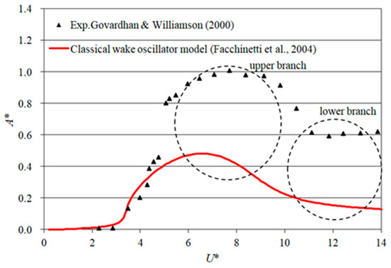
Figure 2.
Comparing of the maximum transverse amplitude calculated by the classical wake oscillator model to the experimental data (m* = 1.2, m*ζ = 0.006) [8,14].
As shown in Figure 2, there is a significant deviation between the calculation results of the classical wake oscillator model and the experimental data, particularly in the upper (lock-in regimes) and lower branches. The calculated A* is clearly smaller than the experimental results at most flow velocities, therefore a lift force compensation is required.
3.2. Modification of Reference Lift Coefficient CL0
There is a relationship between the motion of the cylinder and lift force, and in the lock-in regime, the lift coefficient of the cylinder is expected to increase [21], particularly when m*ζ is small [30,31]. Therefore, in order to improve the accuracy of the classical wake oscillator model in low m*ζ cases, the reference lift coefficient CL0 needs to be modified.
As the lift coefficient varies, the added mass coefficient of the cylinder will also change [32,33]. Meanwhile, the change in lift coefficient and added mass coefficient is closely related to the change in vibration frequency. Therefore, the purpose of this section is to first analyze the variation of added mass versus reduced velocity, as well as the relationship between added mass and lift coefficient, and then modify the reference lift coefficient CL0.
3.2.1. Analysis of Added Mass Coefficient
Prior to analyzing the added mass coefficient (referred to as CA in this section), a frequency domain analysis must be conducted. Govardhan and Williamson [14] have studied in detail the characteristics of cylinder’s vortex-induced vibration with low mass-damping ratio, and concluded that in the upper and lower branches the expression for resonance frequency ratio is
where mD is the potential flow added mass, and mf is an ‘effective’ added mass that includes an apparent effect due to the total transverse fluid force in phase with the body acceleration. For the cylinder with low mass-damping ratio, the frequency of the lower-branch vibration can be expressed as follows:
Meanwhile, as the mass ratio decreases, the value of reduced velocity, defining the start of the lower branch, increases according to the following relation (see Figure 3).
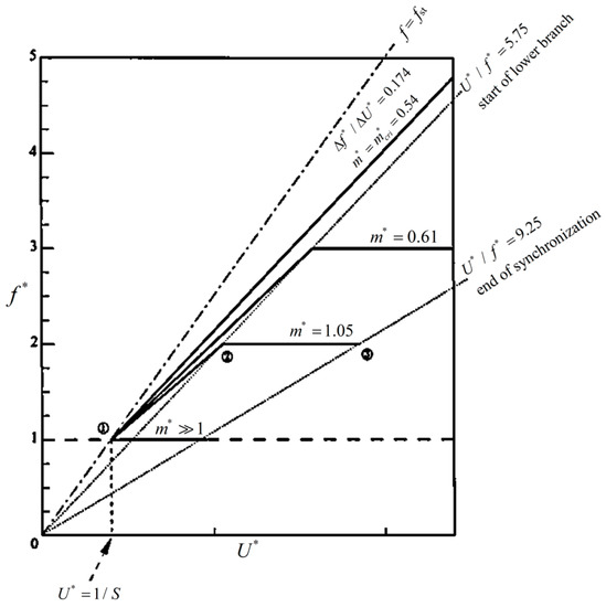
Figure 3.
Frequency response of different mass ratios with low m*ζ [14].
Combining Equations (9) and (10), the added mass coefficient CA in the lower branch for low m*ζ cases can be obtained.
Meanwhile, combining Equations (10) and (11), the velocity defining the start of the lower branch can be obtained.
The frequency response in the upper branch is more complex. As shown in Figure 3, the upper branch starts form about U* = 5. When the mass ratio m* is less than the critical value 0.54, the lower branch will disappear, f* increases linearly with the increase of U*, and the slope is about 0.174 [14]. Therefore, the following relation can be obtained.
Combining Equations (14) and (9), the added mass coefficient CA in the lock-in regimes for m*0.54 cases can be obtained.
When m* is large than 0.54, the upper branch exists in the interval U*~(5, ).
Govardhan and Williamson [14] analyzed the experimental results of typical working conditions of cylinder’s vortex-induced vibration having distinct upper branch, finding that the frequency ratio in the upper branch is approximately a straight line connecting the end of the initial branch and the beginning of the lower branch in the frequency diagram, as shown in Figure 3 (a specific example is shown in Figure 4), which can be expressed as:
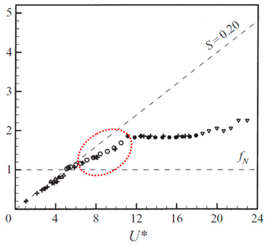
Figure 4.
Frequency response of vortex-induced vibration of cylinder having distinct upper branch (m* = 1.2, ζ = 0.005) [14].
Import Equation (16) into Equations (9) and (10), CA in the upper branch for m* > 0.54 cases can be obtained.
According to the above analysis, CA can be expressed as a piecewise function (Equations (18) and (19)). Considering that the difference of frequency response between high and low m*ζ cases are mainly in the upper and lower branches, the modification of the modified model focuses on these two branches, and the value of CA for the initial branch in the modified model is consistent with the added mass coefficient in the classical model (=1).
3.2.2. Modification of CL0 Based on CA
According to the above analysis, in lock-in regimes, the reference lift coefficient CL0 should increase with the decrease of added mass, which is more apparent for low m* cases. However, in the classical wake oscillator model, the reference lift coefficient CL0 is set as a constant 0.3, fail to reflect this feature. Therefore, in the modified model, we will modify CL0 based on the added mass coefficient CA, and set the expression of CL0 as:
where a is the empirical parameter. The value of a is estimated through experimental data, and is set as a = 0.3 in the modified wake oscillator model. The other parameters in the modified model are all the same as those in the classical model. When CA = 1 or m* is large, , CL00.3, the modified model is equivalent to the classical model. When m* is smaller, the influence of added mass on lift coefficient is greater.
4. Performance Verification of Modified Wake Oscillator Model
This section compares the computation results of the modified wake oscillator model with those of the classical model and experimental data in order to assess its performance.
4.1. Response of Maximum Amplitude
Figure 5 shows the calculation results of the maximum amplitude versus reduced velocity by modified wake oscillator model for four different values of m*ζ and the corresponding results calculated by the classical model. The calculated results are compared with the experimental data [14]. The range of m* is 0.52~12.96, and the range of m*ζ is 0.0027~0.078. In Figure 5a,c, we also plot the results of the modified wake oscillator model proposed in the reference [21] as a comparison.
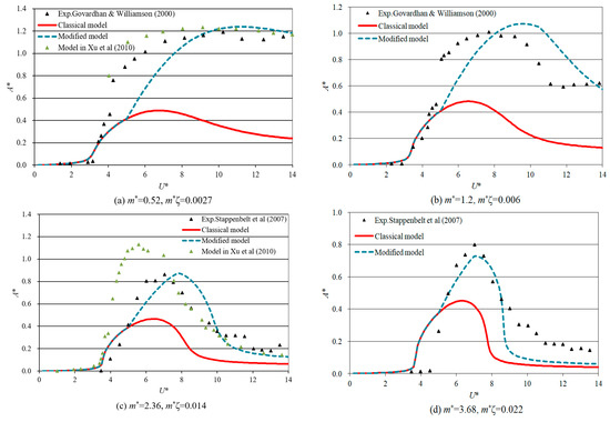
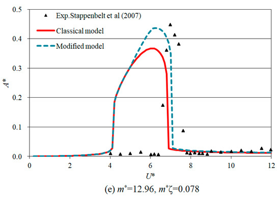
Figure 5.
Responses of the maximum amplitude versus reduced velocity with different m* and ζ (m* = 0.52~12.96, m*ζ = 0.0027~0.078) [14].
As shown in Figure 5, in the initial branch (U* < 5), the modified model produces the same results as the classical model. In upper and lower branches, however, the maximum amplitude calculated by the modified model is larger, which becomes more apparent when m* is smaller. By contrast, the modified model’s calculation results are much closer to the experimental results, particularly in the upper branch. A comparison of the maximum amplitude and corresponding flow velocity in the experimental and calculation results is made to analyze the performance of the modified model, as shown in Table 2. As shown in Figure 5a, both the calculation results of A* of the modified model proposed in this paper and in reference [21] are close to the experimental data, and the accuracy of the model in reference [21] is even better. However, in Figure 5c, Despite reference [21]’s model having significant calculation errors, this paper’s modified model still agrees well with experimental data. It can be inferred that, in contrast to the modification method of refitting the empirical coefficient in reference [21], the modification method of defining the added mass and reference lift coefficient as a function of reduced velocity has a broader application range.
Table 2.
Compare of maximum amplitude and the corresponding velocity in experimental and calculation results.
Based on Table 2, the average error of the modified model wake oscillator in calculating maximum amplitude is 4.9%, whereas the average error of the classical model is 44.7%, which is approximately 9 times greater than that of the modified model. For the calculation of the reduced velocity at maximum amplitude, the average error of the modified model is 9.8%, while the average error of the classical model is 14.4%, which is about 1.5 times that of the former. In these cases, the modified model is capable of capturing the maximum amplitude and the corresponding velocity more accurately than the classical model.
4.2. Response of Vibration Frequency
According to the analysis in the previous section, the modified wake oscillator model is more accurate in calculating the amplitude response of cylinders with low m*ζ, especially in the upper branch. However, as shown in Figure 5, even though the calculation accuracy of the lower branch has improved, the calculation error is relatively higher than that of the upper branch. To determine the cause of this phenomenon, frequency analysis is conducted.
Figure 6 shows the vibration frequency response versus reduced velocity calculated using the modified wake oscillator model and the classical model, which is compared with experimental results.
Figure 6.
Responses of the vibration frequency versus reduced velocity (m* = 2.36, m*ζ = 0.014) [14].
As shown in Figure 6, in terms of vibration frequency, both the modified and classical models exhibit the same trend. As van der Pol oscillator Equation (6) has a significant impact on the frequency characteristics of calculation results, we changed only the reference lift coefficient CL0 in the modified model, which will not alter Equation (6)’s characteristics. Generally, the calculation results for the upper and initial branches are consistent with the experimental results. However, the calculation results for the lower branch are quite different from the experimental results. Especially for U* > 12, the experimental results show a constant vibration frequency, whereas calculation results show a linear increase of vibration frequency.
According to the above analysis, the calculation error of the modified model in the lower branch is primarily due to properties of the equations of the van der Pol oscillator. It is therefore possible to further improve the calculation accuracy for the lower branch by modifying the van der Pol oscillator equation. However, since the maximum amplitude is of greater concern in engineering practice, and the modified wake oscillator model presented in this paper has significantly improved the prediction accuracy of maximum amplitudes for cylinders with low m*ζ, therefore, this paper does not examine further modifications for the lower branch.
4.3. Verification of CA
In this paper, the wake oscillator model is modified by expressing the added mass coefficient CA as a function of the reduced velocity. To verify the correctness of parameter CA in the modified model, the results of CA are compared to numerical simulation results published in the literature [34].
As shown in Figure 7, in upper and lower branches (U* > 5), the calculation results of parameter CA in the modified wake oscillator model are in good agreement with the numerical simulation results in the literature, proving the correctness of the related algorithms in the modified model. In the regime of initial branch (U* < 5), the value of CA is 1, which is corresponded to the classical model. This is in accordance with the expectation since the modification of the improved model only focuses on lock-in regimes.
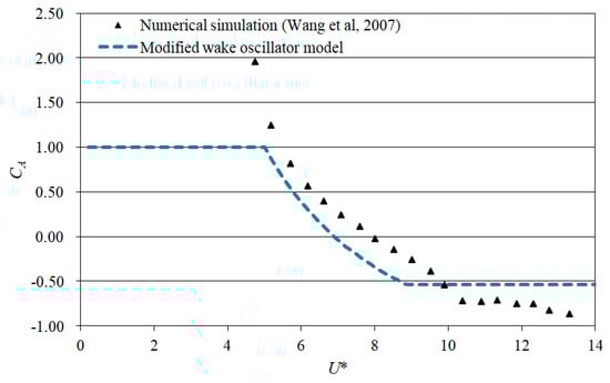
Figure 7.
Variation of CA in the modified wake oscillator model versus reduced velocity (m* = 1.66) [34].
4.4. Analysis of CL0
Figure 8 illustrates the variation of CL0 in the modified wake oscillator model as a function of reduced velocity. As shown in the figure, in the initial branch (U* < 5), CL0 = 0.3, same as that in the classical model. In the lock-in regimes, the value of CL0 in the modified model is larger. When m* is less than the critical mass ratio ( = 0.54), CL0 increases continuously with U*, but the growth rate decreases gradually; when m* > 0.54, the value of CL0 increases smoothly in the upper branch and then remains constant in the lower branch. Meanwhile, with an increase of m*, the velocity range corresponding to the upper branch becomes obviously narrower. At the same time, the maximum CL0 will be decreased and approached to 0.3. When m* = 0.52, the value of maximum CL0 in the modified model is about 0.56, more than 86% larger than CL0 (=0.3) in the classical model; when m* = 12.96, the value of maximum CL0 in the modified model is 0.33, only 10% larger than that in the classical model. With the further increase of m*, the difference between the improved model and the classical model will be further reduced, insuring that in high m*ζ cases, the improved model is equivalent to the classical model.
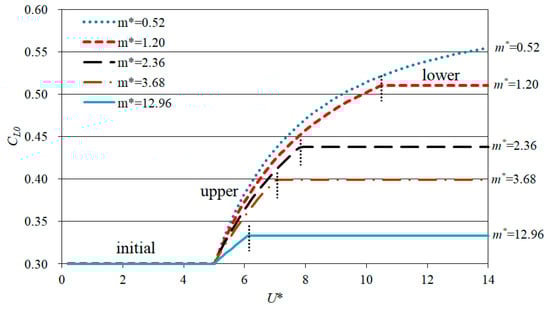
Figure 8.
Variation of CL0 in the modified wake oscillator model versus reduced velocity with different m*.
Since the improvement in this paper is primarily directed at the lift coefficient, the rationality of the above improved method will be verified by analyzing the lift coefficient. Take the test condition of m* = 2.36, m*ζ = 0.014 as an example, the value of parameter CL0*q (the parameter characterizing the lift force) is compared with numerical simulation results at different flow velocities (See Figure 9). An in-depth description of the numerical simulation method can be found in the author’s previous work [35].
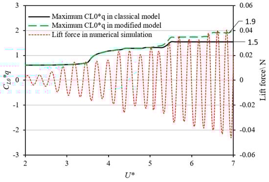
Figure 9.
Change trend of CL0*q in different models and the lift force versus reduced velocity (m* = 2.36, m*ζ = 0.014).
As shown in Figure 9, as the flow velocity increases, the change trend of parameter CL0*q in the modified wake oscillator model is more closely related to the numerical simulation results than in the classical model. In the initial branch, both models produce similar results. However, upon a further increase of flow velocity, when U* > 5 (comes to lock-in regimes), differences between the two models became apparent. Especially when U* > 6.5, the classical model fails to capture the enhancement of lift coefficient, and the calculation error exceeds 33%, while the modified model is in good agreement with the numerical simulation results. The above results show that the modified model proposed in this paper can better capture the change trend of the lift coefficient of the cylinder’s vortex-induced vibration with low mass-damping ratio.
4.5. Limitations of the Modified Wake Oscillator Model
To identify the limitations of the modified model, the calculation results of the modified wake oscillator model are compared with those of the author’s recent experiments (See Figure 10). The basic parameters of the cylinder are: D = 40mm, m* = 4.5, m*ζ = 0.5, fn = 1.6 Hz. A notable feature of this system is that the cylinder has a relatively low mass ratio, while the damping ratio of the system is relatively high.
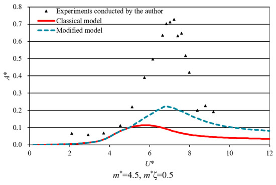
Figure 10.
Responses of the maximum amplitude versus reduced velocity (m* = 4.5, m*ζ = 0.5).
As shown in Figure 10, despite the modified model’s calculated A* being closer to the experimental value than the classical model, the calculation error is substantial. In particular, the maximum amplitude calculation error is approximately 68%, which is insufficient to meet engineering forecasting requirements. These results indicate that the modified wake oscillator model at present form is not suitable for cases with high damping ratios (although the mass ratio is low).
In order to analyze the cause of calculation errors, the frequency responses of the present experiments (with high damping ratio and low mass ratio) are compared with those reported in the literature (with low mass and damping ratios), as shown in Figure 11.
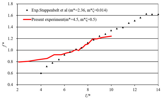
Figure 11.
Comparison of vortex-induced vibration frequency responses of cylinders with different mass and damping parameters [14].
Figure 11 shows that the two frequency response curves in the figure exhibit different trends. It is evident that the slope of the curve with high damping ratio is much smaller than that of the curve with low damping ratio, and the locations of their inflection points are also different. This indicates that the response characteristics of vortex-induced vibration differ significantly between these two cases, including the change trend of added mass and lift coefficient, etc. Since the modification method proposed in this paper is based on the response characteristics of vortex-induced vibrations with low mass and damping ratios, it is apparent that the modified model at present form cannot accurately predict the vortex-induced vibration response at high damping ratios, even when the mass ratio is low.
5. Conclusions
It has been demonstrated that the classical wake oscillator model is capable of predicting the vortex-induced vibration response of the cylinder for high mass-damping ratios, but not for low mass-damping ratios. This paper proposes a modified wake oscillator model based on the classical model in order to address this problem. In this method, the added mass coefficient of the cylinder is analyzed in relation to reduced velocity, and then the reference lift coefficient CL0 is expressed as a function of the added mass coefficient. A comparison of the modified wake oscillator model with experimental results and the classical model is conducted in order to evaluate the performance of the modified wake oscillator model.
Results show that the modified model can greatly improve the accuracy of prediction of the vortex-induced vibration of a cylinder, particularly in capturing the maximum amplitude and the corresponding flow velocity for low m*ζ cases.
It should still be noted that, the main purpose of this paper is to propose a new modification idea, and verify its rationality. The modified model at present form is unable to accurately predict the vortex-induced vibration response at high damping ratios. The application of this modification idea to specific objects may require us to understand the response law of these kinds of objects first, and then combine the modification methods available in the other existing literature in order to obtain better results.
In conclusion, the proposed model has the following capacities and limitations.
Capacities:
- (1)
- The modified model is applicable to 1DOF vortex-induced vibration of cylinders with both small mass and damping ratios.
- (2)
- The modified model can capture the maximum amplitude and the corresponding velocity more accurately than the classical model.
- (3)
- The modified model can more accurately reflect the trends in added mass and lift coefficient as a function of reduced velocity.
Limitations:
- (1)
- The modified model at present form cannot accurately predict the vortex-induced vibration response at high damping ratios, even when the mass ratio is low.
- (2)
- The modified model does not accurately capture the frequency response characteristics of the lower branch of vortex-induced vibration.
Author Contributions
Conceptualization, W.N. and X.Z. (Xu Zhang); methodology, L.X.; software, L.Y.; validation, G.T., Y.M. and W.Y.; formal analysis, S.Z.; investigation, Y.M.; resources, Y.H.; data curation, W.Y.; writing—original draft preparation, X.Z. (Xiulin Zhang); writing—review and editing, X.Z. (Xu Zhang); visualization, Y.H; supervision, X.Z. (Xu Zhang); project administration, L.X.; funding acquisition, W.N. All authors have read and agreed to the published version of the manuscript.
Funding
This research was funded by [National Natural Science Foundation of China] grant number [52001112]; [National Key R&D Program of China] grant number [2022YFC2806300]; [Guangdong Branch of National Engineering Research Center for Offshore Windpower] grant number [2019B090904005]. And The APC was funded by [Guangdong Branch of National Engineering Research Center for Offshore Windpower].
Institutional Review Board Statement
Not applicable.
Informed Consent Statement
Not applicable.
Conflicts of Interest
The authors declare no conflict of interest.
References
- Zhang, X.; Ni, W.; Sun, L. Fatigue Analysis of the Oil Offloading Lines in FPSO System underWave and Current Loads. J. Mar. Sci. Eng. 2022, 10, 225. [Google Scholar] [CrossRef]
- Ni, W.; Zhang, X.; Xu, F.; Zhang, W. Modified approximation method for structural failure probability analysis of high-dimensional systems. Ocean. Eng. 2021, 237, 109486. [Google Scholar] [CrossRef]
- Kang, Z.; Zhang, C.; Ma, G.; Ni, W. A numerical investigation of two-degree-of-freedom VIV of a circular cylinder using the modified turbulence model. Ocean. Eng. 2018, 155, 211–226. [Google Scholar] [CrossRef]
- Ulveseter, J.; Thorsen, M.; Saevik, S.; Larsen, C.M. Time domain simulation of riser VIV in current and irregular waves. Mar. Struct. 2018, 60, 241–260. [Google Scholar] [CrossRef]
- Zhang, M.; Xu, F.; Iseth, O. Aerodynamic damping models for vortex-induced vibration of a rectangular 4:1 cylinder: Comparison of modeling schemes. J. Wind. Eng. Ind. Aerodyn. 2020, 205, 104321. [Google Scholar] [CrossRef]
- Lu, Y.; Luo, Q.; Liao, Y.; Xu, W. Vortex-induced vibration fatigue damage prediction method for flexible cylinders based on RBF neural network. Ocean. Eng. 2022, 254, 111344. [Google Scholar] [CrossRef]
- Li, T.; An, C.; Duan, M. Prediction of coupled in-line and cross-flow vortex-induced vibrations of fluid-transporting free-spanning submarine pipelines: An integral transform solution. Ships Offshore Struct. 2022, 17, 2282–2291. [Google Scholar] [CrossRef]
- Facchinetti, M.L.; Langre, E.D.; Biolley, F. Coupling of structure and wake oscillators in vortex-induced vibrations. J. Fluids Struct. 2004, 19, 123–140. [Google Scholar] [CrossRef]
- Opinel, P.A.; Srinil, N. Application of wake oscillators to two-dimensional vortex-induced vibrations of circular cylinders in oscillatory flows. J. Fluids Struct. 2020, 96, 103040. [Google Scholar] [CrossRef]
- Griffin, O.M.; Skop, R.A.; Koopmann, G.H. The vortex-excited resonant vibrations of circular cylinders. J. Sound Vib. 1973, 31, 235–249. [Google Scholar] [CrossRef]
- Nielsen, S.R.K. Energy Balanced Double Oscillator Model for Vortex-Induced Vibrations. J. Eng. Mech. 1996, 125, 263–271. [Google Scholar]
- Plaschko, P. Global chaos in flow-induced oscillations of cylinders. J. Fluids Struct. 2000, 14, 883–893. [Google Scholar] [CrossRef]
- Kurushina, V.; Postnikov, A.; Franzini, G.; Pavlovskaia, E. Optimization of the Wake Oscillator for Transversal VIV. J. Mar. Sci. Eng. 2022, 10, 293. [Google Scholar] [CrossRef]
- Govardhan, R.; Williamson, C.H.K. Modes of vortex formation and frequency response of a freely vibrating cylinder. J. Fluid Mech. 2000, 420, 85–130. [Google Scholar] [CrossRef]
- Gabbai, R.D.; Benaroya, H. An overview of modeling and experiments of vortex-induced vibration of circular cylinders. J. Sound Vib. 2005, 282, 575–616. [Google Scholar] [CrossRef]
- Feng, C.C. The Measurement of Vortex-Induced Effects in Flow Past a Stationary and Oscillating Circular and D-Section Cylinders. Master’s Thesis, University of British Columbia, Vancouver, BC, Canada, 1968. [Google Scholar]
- Sui, J.; Wang, J.; Liang, S.; Tian, Q. VIV suppression for a large mass-damping cylinder attached with helical strakes. J. Fluids Struct. 2016, 62, 125–146. [Google Scholar] [CrossRef]
- Khalak, A.; Williamson, C.H.K. Investigation of relative effects of mass and damping in vortex-induced vibration of a circular cylinder. J. Wind. Eng. Ind. Aerodyn. 1997, 69–71, 341–350. [Google Scholar] [CrossRef]
- Pastrana, D.; Cajas, J.C.; Lehmkuhl, O.; Rodríguez, I.; Houzeaux, G. Large-eddy simulations of the vortex-induced vibration of a low mass ratio two-degree-of-freedom circular cylinder at subcritical Reynolds numbers. Comput. Fluids 2018, 173, 118–132. [Google Scholar] [CrossRef]
- Konstantinidis, E.; Zhao, J.; Leontini, J.S.; Jacono, D.L.; Sheridan, J. Phase dynamics of effective drag and lift components in vortex-induced vibration at low mass–damping. J. Fluids Struct. 2020, 96, 103028. [Google Scholar] [CrossRef]
- Xu, W.; Wu, Y.; Zeng, X.; Zhong, X.F.; Yu, J.X. A new wake oscillator model for predicting vortex induced vibration of a circular cylinder. J. Hydrodyn. 2010, 22, 381–386. [Google Scholar] [CrossRef]
- Farshidianfar, A.; Zanganeh, H. A modified wake oscillator model for vortex-induced vibration of circular cylinders for a wide range of mass-damping ratio. J. Fluids Struct. 2010, 26, 430–441. [Google Scholar] [CrossRef]
- Kurushina, V.; Pavlovskaia, E.; Postnikov, A.; Wiercigroch, M. Calibration and comparison of VIV wake oscillator models for low mass ratio structures. Int. J. Mech. Sci. 2018, 142, 547–560. [Google Scholar] [CrossRef]
- Qu, Y.; Metrikine, A.V. A single van der pol wake oscillator model for coupled cross-flow and in-line vortex-induced vibrations. Ocean. Eng. 2020, 196, 106732. [Google Scholar] [CrossRef]
- Srinil, N.; Opinel, P.A.; Tagliaferri, F. Empirical sensitivity of two-dimensional nonlinear wake–cylinder oscillators in cross-flow/in-line vortex-induced vibrations. J. Fluids Struct. 2018, 83, 310–338. [Google Scholar] [CrossRef]
- Fujarra, A.L.C.; Pesce, C.P. Added Mass Variation and Van der Pol Models Applied to Vortex-Induced Vibrations. In Proceedings of the ASME 2002 International Mechanical Engineering Congress and Exposition, 5th International Symposium on Fluid Structure Interaction, Aeroelasticity, and Flow Induced Vibration and Noise, New Orleans, LA, USA, 17–22 November 2002; pp. 207–211. [Google Scholar] [CrossRef]
- Cunha, L.D.; Pesce, C.P.; Wanderley, J.; Fujarra, A.L. The Robustness of the Added Mass in VIV Models. In Proceedings of the 25th International Conference on Offshore Mechanics and Arctic Engineering, Hamburg, Germany, 4–9 June 2006; pp. 731–738. [Google Scholar] [CrossRef]
- Fujarra, A.L.C. Experimental and Analytical Studies of Vortex-Induced Vibration in Flexible and Rigid Cylinders. Ph.D. Thesis, University of São Paulo, São Paulo, Brazil, 2002. (In Portuguese). [Google Scholar] [CrossRef]
- Langre, E.D. Frequency lock-in is caused by coupled-mode flutter. J. Fluids Struct. 2006, 22, 783–791. [Google Scholar] [CrossRef]
- Kang, Z.; Ni, W.; Sun, L. A numerical investigation on capturing the maximum transverse amplitude in vortex induced vibration for low mass ratio. Mar. Struct. 2017, 52, 94–107. [Google Scholar] [CrossRef]
- Ni, W.; Zhang, X.; Xu, F.; Zhang, W.; Kang, Z. Numerical investigation of bifurcation characteristics under perturbations in vortex induced vibration of cylinder with two degrees of freedom. Ocean. Eng. 2019, 188, 106318. [Google Scholar] [CrossRef]
- Qu, Y.; Metrikine, A.V. A wake oscillator model with nonlinear coupling for the vortex-induced vibration of a rigid cylinder constrained to vibrate in the cross-flow direction. J. Sound Vib. 2019, 469, 115161. [Google Scholar] [CrossRef]
- Sarpkaya, T. A critical review of the intrinsic nature of vortex-induced vibrations. J. Fluids Struct. 2004, 19, 389–447. [Google Scholar] [CrossRef]
- Wang, Y.; Chen, W.; Lin, M. Variation of added mass and its application to the calculation of amplitude response for a circular cylinder. China Ocean. Eng. 2007, 21, 429–437. [Google Scholar]
- Kang, Z.; Ni, W.; Zhang, X.; Sun, L. Two improvements on numerical simulation of 2-DOF vortex-induced vibration with low mass ratio. China Ocean. Eng. 2017, 31, 764–772. [Google Scholar] [CrossRef]


Disclaimer/Publisher’s Note: The statements, opinions and data contained in all publications are solely those of the individual author(s) and contributor(s) and not of MDPI and/or the editor(s). MDPI and/or the editor(s) disclaim responsibility for any injury to people or property resulting from any ideas, methods, instructions or products referred to in the content. |
© 2023 by the authors. Licensee MDPI, Basel, Switzerland. This article is an open access article distributed under the terms and conditions of the Creative Commons Attribution (CC BY) license (https://creativecommons.org/licenses/by/4.0/).