Article

UAV Relay Energy Consumption Minimization in an MEC-Assisted Marine Data Collection System

College of Information Engineering, Shanghai Maritime University, Shanghai 201306, China
*
Author to whom correspondence should be addressed.
J. Mar. Sci. Eng. 2023, 11(12), 2333; https://doi.org/10.3390/jmse11122333
Submission received: 2 October 2023 / Revised: 20 November 2023 / Accepted: 1 December 2023 / Published: 10 December 2023

Abstract

:
Recently, unmanned aerial vehicle (UAV)-assisted maritime communication systems have drawn considerable attention due to their potential for broadband maritime communication applications. However, their limited energy resources remains a critical issue in providing long-term data transmission support for maritime applications. In this study, an integrated sea–air–terrestrial communication system was constructed for marine data collection, where several unmanned surface vessels (USVs) are deployed to collect marine data from underwater sensors (UWSs), and a UAV hovers above these USVs as a relay node, transmitting marine data from USVs to an onshore base station (BS). To prolong the lifetime of the UAV relay, mobile edge computing technology is applied in USVs for partial data computing, which reduces the to-be-relayed data volume from UAVs to USVs to onshore BS as well as the relay energy consumption of UAV. A parallel data computing and transmission scheme was developed for simultaneous local data computing and relaying in the proposed system. Accordingly, a UAV energy consumption minimization problem was formulated with constraints on the USV’s computational ability, the USV’s transmission power budget, the UAV transmission power budget, and the maximum system latency. To effectively solve this nonconvex optimal problem, an energy optimal partial data computing and relaying strategy was constructed by successively optimizing the data partial computational offloading ratio, USV transmit power allocation, and UAV transmit power. Numerical simulations were used to verify the effectiveness of the proposed strategy.

1. Introduction

With ever-increasing maritime activity, the maritime Internet of Things (MIoT) has been designed to enable reliable and efficient communication for supporting maritime applications such as ocean exploration, environment and pollution monitoring, traffic, and logistics management [1]. However, due to the special characteristics of marine environments, terrestrial IoT technologies cannot be directly applied in these contexts. Different from the terrestrial IoT, the transmission nodes in marine environments are usually sparsely deployed in unattended regions, so efficient data transmission is particularly challenging in offshore areas with restricted communication resources [2]. Moreover, given the complexity of marine environment, the whole signal transmission process may need to be accomplished through various types of transmission media, including wireless radio frequency, underwater acoustic wave, underwater laser, etc., which leads to heterogeneous architectures and transmission characteristics in MIoT systems.
To complete the vast amount of ocean data collection tasks in MIoT systems, three different types of maritime data collection platforms can be used according to the relay nodes, namely shore-based radar systems, aerial-based high-altitude platforms, or satellites and survey vessels, most of which involve the following procedure: First, the marine data collected using MIoT sensors deployed on sea surface or underwater are gathered by aggregation nodes on the sea surface before being transmitted to ground servers for further analysis. However, restricted by limited communication resources and service duration, these platforms are not able to support long-term or high-capacity data collection. Furthermore, as recent information is crucial to user decision making [3,4], real-time transmission should be considered in the design of a marine data collection system. Although several advanced technologies, such as a buffer-assisted relay and the hybrid RF-FSO data transmission scheme, have been studied to enhance the abilities of terrestrial wireless communication system [5,6], low-latency broadband data transmission in marine environments relying solely on the aforementioned solutions remains challenging.

1.1. Related Literature

The rapid development of the unmanned aerial vehicle (UAV)-assisted IoT has provided feasible solutions to the problem discussed above. By taking advantage of their high mobility and maneuverability, aerial-based transmission nodes often serve as temporary communication base stations to cover holes in offshore area. They also serve as data storage or as relay nodes for marine data collection [7]. Furthermore, to meet the transmission delay requirements of maritime communication applications, mobile edge computing (MEC) [8] can be integrated into MIoT systems to enhance a system’s latency performance [9,10]. A two-stage task-offloading scheme was proposed to improve the latency performance on computation-intensive maritime tasks in a UAV-assisted MIoT system [9]. A UAV-assisted data-offloading model was investigated for smart containers in offshore maritime communications [10]. A data-offloading algorithm was proposed to reduce the average offloading delay. Considering the importance of UAV trajectory in system performance, a joint UAV trajectory and resource allocation problem was studied to improve the energy efficiency of UAV-assisted MIoT networks [11,12]. Energy-efficient offloading transmission issues were discussed in terms of UAV mobility in a UAV-assisted MIoT system, where computation-intensive maritime tasks in US offloading via nonorthogonal multiple access (NOMA) with an MEC-enabled UAV. Energy-efficient UAV trajectories were obtained using a deep reinforcement learning (DRL) method [11]. A low-complexity resource allocation algorithm was developed to jointly optimize UAV hovering placement and minimize UAV energy consumption in a UAV-assisted MIoT [12]. Researchers [13] proposed a cooperative hybrid NOMA-based mobile edge computing system for cognitive radio networks. The performance of NOMA and orthogonal multiple access was evaluated for an MEC-enabled NOMA system [14,15].
Advanced optimization methods, such as the multiagent optimization, meta-heuristic, and DRL methods, have been introduced to terrestrial IoT systems [16,17,18,19,20,21]. A novel socially aware radio map framework was proposed for improving the QoS of UAV-assisted MEC networks [16]. In [17], the authors solved a joint trajectory and resource optimization problem of MEC-assisted UAVs by designing a resource-based multiagent proximal policy optimization deep reinforcement learning (DRL) algorithm with an attention mechanism. In [18], the authors developed a meta-heuristic method to solve offloading and communication allocation optimization problem for UAV-assisted MEC networks in rural areas. Researchers [19] proposed a multiagent policy gradient-based deep actor–critic algorithm to solve the offloading and resource allocation problems in heterogenous aerial access IoT networks. A DRL-based resource optimization framework was proposed for a high-altitude platform-assisted vehicular edge computing system [20]. In [21], the rate-splitting multiple access technique was introduced to enhance the performance of the proposed system. Although these advanced optimization methods improve the performance of MEC-enabled systems, they are unsuitable for marine communication environments because of their higher computing energy consumption. The comparison of related methods and our method is summarized in Table 1 with respect to scenario, UAV function, MEC technique, and metrics.

1.2. Motivations and Contributions

Despite the efforts focused on MIoT systems in the above-mentioned studies, minimizing the aerial relay energy consumption, which critically affects the lifetime of the UAV-assisted MIoT systems, remains a challenge. Therefore, in this study, we designed a sea–air–terrestrial marine data collection system where UAV relay and several MEC-enabled unmanned surface vessels (USVs) are deployed to relay the data collected from underwater sensors (UWSs) to an on-shore base station (OSBS). Partial computation offloading technology is used in MEC-enabled USVs to reduce relay data traffic and reduce the transmission energy consumed by UAV relays in situations with small energy reserves. An energy optimal parallel data computational offloading and relay strategy was developed to minimize the UAV energy consumption while jointly optimizing communication and mobile computation resources. The main contributions of this study are as follows:
  • To prolong the lifetime of a marine data collection system, we constructed a two-hops relay network, where one aerial relay node collaborates with several MEC-enabled USVs to efficiently perform data collection tasks. Considering the restricted communication and energy resources in marine wireless communication scenarios, a partial computing offloading scheme was applied in the proposed network. Accordingly, an aerial node energy minimization problem was formulated, constrained by limited communication and computing resources as well as system latency requirements.
  • We developed an energy optimal parallel partial computing and relay strategy to solve the nonconvex energy minimization problem based on a parallel computing and transmit scheme, and we obtained the optimal partial offloading factor vector in closed form. We acquired the optimal USV transmission power and optimal UAV relay transmission power using a two-step iterative optimizing method.
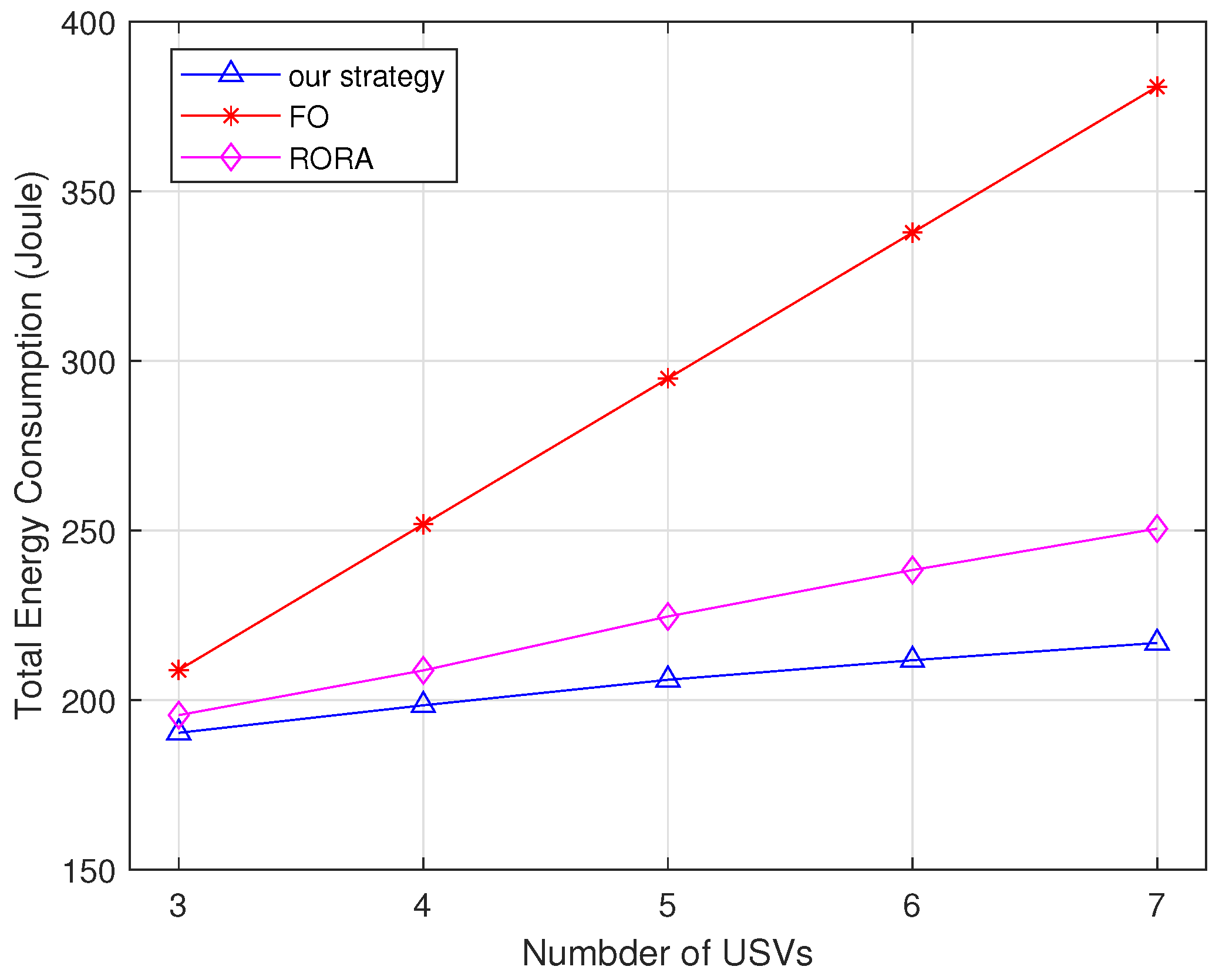
  • The numerical results verified the effectiveness of our proposed strategy, which offers a feasible solution to prolong the lifetime of aerial-assisted marine data collection systems. Our strategy outperforms the benchmark methods in terms of aerial relay energy savings.
The rest of this paper is organized as follows: The design of the sea–aerial–terrestrial marine data collection system is described in Section 2. In Section 3, we describe the formulation of a UAV energy consumption minimization problem, with constraints considering USV local computational capabilities, system latency requirements, and USV and UAV transmission power budgets. The energy optimal parallel partial computing and relay strategy is outlined in Section 4. Numerical results and discussion are provided in Section 5. Finally, the conclusions are outlined in Section 6.

2. System Model

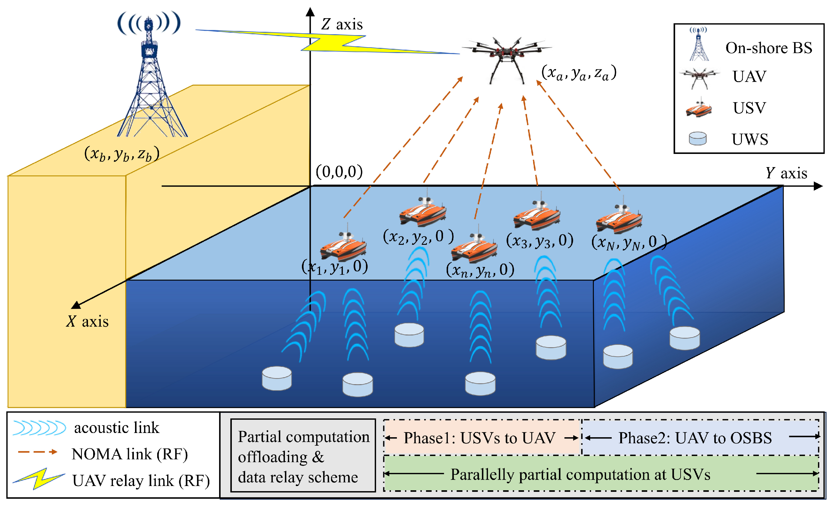
2.1. System Architecture Design

As illustrated in Figure 1, a sea–air–terrestrial integrated communication system is constructed for marine data communication where a set of USVs, denoted as N = { 1 , 2 , , n , , N } , sail on the ocean surface to aggregate data from a group of UWSs through acoustic links. A UAV hovering above acts as a relay node for shipping data from USVs to OSBS through radio frequency (RF) links. Table 2 displays the notations used in system model and problem formulation.
The three-dimensional Cartesian coordinate system is adopted for the locations of USV, UAV, and OSBS. The coordinates of the nth USV, UAV, and OSBS are expressed by ( x n , y n , 0 ) , ( x a , y a , z a ) , and ( x b , y b , z b ) , respectively. The distances between the nth USV and UAV, between the UAV and the OSBS, respectively, are
d n a = x n x a 2 + y n y a 2 + z a 2 ,
d a b = x a x b 2 + y a y b 2 + z a z b 2 .
Considering the characteristics of RF propagation in ocean surface environments, a composite channel model, composed of large- and small-scale fading, was adopted in this study to model the channel, which has both line-of-sight (LoS) and non-line-of-sight (nLoS) components [22,23]. Thus, the air-to-sea (A2S) channel between the nth USV and the UAV is modeled as
h n a = h ˜ n a L n a 1 / 2 ,
where h ˜ n a is the Rician fading component for the A2S link, and L n a is the large-scale fading coefficient between the nth USV and UAV, which is written as
L n a dB = A n a + 10 ζ n a log 10 d n a d 0 + X n a .
In Equation (4), d 0 denotes the reference distance, A n a is the path loss at d 0 , ζ n a is the path loss exponent, and X n a is a random zero-mean Gaussian variable with standard deviation σ X n a . The air-to-air (A2A) channel between the UAV and OSBS can be expressed as
h a b = d 0 d a b ζ a b 2 10 A a b + X a b 20 h ˜ a b ,
where A a b , ζ a b , and X a b denote the path loss at d 0 , the path loss exponent, and a random zero-mean Gaussian variable with standard deviation σ X a b , respectively. h ˜ a b is the Rician fading component for the A2A link. Because the A2A channel has a high LoS probability, it can be distinguished from the A2S link model using these parameters.
As shown in Figure 1, to reduce the spectrum and energy consumed in the proposed resource-limited integrated sea–air–terrestrial communication system, we developed a parallel partial computational offloading and data relay scheme. Specifically, this partial computation offloading scheme enables a USV to use a partial computational process for the aggregated marine data from UWSs before relaying them to the UAV. Additionally, by taking advantage of parallelism for data-partitioned and -oriented applications [24,25], a portion of the total data is processed by the nth USV, whereas the remaining part is simultaneously relayed to the OSBS by the UAV.

2.2. Partial Computational Offloading Model

In the proposed system, MEC technology is enabled in the USVs. We model the power consumption of the CPU in the nth USV as κ n ( f n ) 3 , as in [26], where f n and κ n denote the CPU’s computational speed and a coefficient depending on chip architecture, respectively. We suppose that r n denotes the aggregated marine data volume in the nth USV from UWSs. The number of cycles C n needed for data computation is modeled as the number of input data multiplied by a factor, which is denoted as C n = α r n , where α α > 0 is a computational complexity factor. We set β n 0 β n 1 as the ratio of the executed data volume to the total input data in the nth USV. Thus, the time spent for data computation in the nth USV can be expressed as
t n c m p = β n C n f n = β n α r n f n .
According to (6), the data computing latency of a USV differs from its computational capability. Therefore, we define the overall data computing latency of all USVs as t U S V c m p = max n N t n c m p , which shows that the overall USV computing latency is determined by the USV with the maximum computing latency in the set of USVs.
The energy consumed to compute the data in the nth USV can be expressed as
E n c m p = β n C n κ n f n 2 = β n α r n κ n f n 2 .

2.3. Data Relaying Model

As shown in Figure 1, relaying the data involves two phases, i.e., USVs-to-UAV transmission and UAV-to-OSBS relay. In the first phase, the UAV receives data from the USVs via uplink NOMA. In the second phase, the UAV relays the received data to the OSBS. The channel gains of the links between the UWSs and UAV can be ordered as h 1 a 2 h 2 a 2 h n a 2 h N a 2 . Therefore, the data rate to the UAV from the nth USV is expressed as
R n a = B a log 2 1 + p n h n a 2 N a + i < n , i N p i h i a 2 , = B a log 2 1 + p n g n a 1 + i < n , i N p i g i a ,
where p n denotes the nth USV’s transmission power, B a is the bandwidth of the NOMA link, N a denotes the A2S background noise power, and g n a = h n a 2 N a , n N . We denote t U S V t r s as the transmission latency from the USVs to the UAV via NOMA. Then, the data transmission energy consumed by the nth USV can be written as
E n t r s = t U S V t r s p n a .
After receiving the data, the UAV successively transmits them to the OSBS in the second phase. The rate the data are received at OSBS from the UAV can be written as
R a b = B b log 2 1 + p a b h a b 2 N b = B b log 2 1 + p a b g a b ,
where p a b is the UAV transmission power, B b is the bandwidth of the link between the UAV and the OSBS, N b is the A2A background noise power, and g a b = h a b 2 N b . t U A V t r s denotes the data transmission latency from the UAV to the OSBS; then, we have
t U A V t r s = n N 1 β n α r n R a b .
The total energy consumed by the UAV can be written as
E U A V t o t a l = p h o v t U S V t r s + t U A V t r s + t U A V t r s p a b ,
where p h o v denotes the UAV hovering power. E U A V h o v = p h o v t U S V t r s + t U A V t r s and E U A V t r s = t U A V t r s p a b denote the UAV energy consumed for hovering and data transmission, respectively.

3. Problem Formulation

In the proposed system, the lifetime of the UAV relay node critically affects the lifetime of whole data collection network due to its energy vulnerability. Therefore, in this study, we focused on minimizing the energy consumption of the UAV relay while considering the computation capabilities of the USVs, system latency requirements, and the transmission capability of each node. The optimization problem is formulated as follows:
min β , p , p a b E U A V t o t a l s . t . C 1 : 0 β n 1 , n N C 2 : 0 E n c m p E ¯ n c m p , n N C 3 : 0 p n p ¯ s , n N C 4 : 0 p a b p ¯ A C 5 : max t U S V c m p , t t r s T ,
where t t r s = t U S V t r s + t U A V t r s , β = β 1 , β 2 , , β n , , β N denotes the partial data computation offloading ratio vector, and p = p 1 , p 2 , , p n , , p N denotes the transmission power vector of the N USVs. E ¯ n c m p , p ¯ s , and p ¯ A are the computing energy budget of the nth USV, the transmission power budget per USV, and the UAV transmission power budget, respectively.
In Problem (13), C1 is the partial data computation offloading ratio constraint of the nth USV. β = 1 expresses all received data r n that have been processed in the nth USV, whereas β = 0 means that no data have been locally computed by the nth USV. C2 guarantees that the computing energy consumed by the nth USV does not exceed its local computing energy budget E ¯ n c m p . C3 and C4 guarantee that the transmission power of the USV and UAV should not exceed the given budgets p ¯ s and p ¯ A , respectively. C5 reflects the latency constraint, which guarantees that either the overall USV computing latency t U S V c m p or two-phase data transmission latency t t r s should not exceed the system latency requirement T. The optimal problem is nonconvex due to the nonconvexity of the objective function and C5. Therefore, optimal Problem (13) is nonconvex, which is difficult to solve.

4. Energy Optimal Parallel Data Computation and Relaying Strategy

To minimize the total UAV energy consumption, both hovering and transmission energy should be minimized according to optimal Problem (13). In this section, we propose an energy optimal parallel data computing and relaying strategy to solve nonconvex Problem (13) by successively optimizing the partial computation offloading ratio, USV transmission power allocation, and UAV transmission power allocation.

4.1. Partial Computation Ratio Vector Optimization

In the proposed optimal Problem (13), the total UAV energy consumption is affected by the energy consumed by the UAV to hovering and transmit data, which are determined by the total two-phase transmission latency and the to-be-relayed data volume in the UAV. To apply parallel data computing, reducing the to-be-transmitted data volume can efficiently decrease the energy required for data transmission in both relay phases with the given channel state information. Additionally, constrained by the system latency requirement, a smaller to-be-transmitted data volume consumes less energy when relayed. Hence, the optimal partial computation ratio problem can be formulated as a partial computation ratio maximization problem for an arbitrary USV with respect to the partial computation ratio vector β , which is constrained by its computing ability E ¯ n c m p and total system latency T as follows:
β = arg max n N β n s . t . C 1 : 0 β n 1 , n N C 2 : β n α r n κ n f n 2 E ¯ n c m p , n N C 6 : max n N β n α r n f n T ,
where C6 guarantees that the maximum USV local computing latency does not exceed the system latency requirement. According to objective function in Problem (14), optimal solution β * can be obtained by acquiring the maximum β n in the feasible area, determined by constraints C1, C2, and C6. Then, for an arbitrary β n , the optimal computation ratio solution can be obtained as
β n * = 1 , case 1 ; f n T α r n , case 2 ; E n c m p ¯ α r n κ n f n 2 , case 3 .
Equation (15) is the optimal solution to Problem (14), which includes three cases, described as follows:
  • In Case 1, all received data r n are processed in the nth USV. Simultaneously, E n c m p = α r n κ n f n 2 E ¯ n c m p and t n c m p = α r n f n T are satisfied. Thus, the computing time of the nth USV is t n c m p = α r n f n . There are no remaining data to be transmitted to the nth USV, i.e., 1 β n * α r n = 0 and p n = 0 . Therefore, no data transmission energy is consumed by the UAV from the nth USV.
  • In Case 2, the computational capability of the nth USV is constrained by transmission latency T. Thus, the computing time of the nth USV is t n c m p = T , and f n T is the already-processed data volume. The remaining to-be-transmitted data volume in the nth USV is 1 β n * α r n = 1 f n T α r n α r n .
  • In Case 3, the computational capability of the nth USV is constrained by the maximum computing energy budget E ¯ n c m p , and E ¯ n c m p κ n f n 2 is the already-processed data volume. The computing time of the nth USV is t n c m p = E ¯ n c m p κ n f n 3 . The remaining to-be-transmitted data volume in the nth USV is 1 β n * α r n = 1 E ¯ n c m p α r n κ n f n 2 α r n .

4.2. Transmission Latency Optimization

With the optimal partial computation ratio vector, the original Problem (13) can be reformulated as
min p , p a b p h o v t U S V t r s + p h o v + p a b n N 1 β n * α r n R a b s . t . C 3 : 0 p n p ¯ s , n N C 4 : 0 p a b p ¯ A C 5 : max t U S V c m p , t U S V t r s + t U A V t r s T .
Problem (16) is nonconvex due to objective function and C5. Then, we transform C5 by resolving it into two kinds of latency determined cases, expressed as
max t U S V c m p , t U S V t r s + t U A V t r s = C 5 1 : t U S V c m p T , t U S V t r s + t U A V t r s t U S V c m p ; C 5 2 : t U S V t r s + t U A V t r s T , t U S V c m p < t U S V t r s + t U A V t r s ,
where C5-1 represents the system latency constraint determined by the computing latency, and C5-2 represents the system latency constraint determined by the two-phase transmission latency. Then, we solve Problem (16) in two cases, separately, namely partial computing- and data transmission-dominated latency.

4.2.1. Partial Computing-Dominated Latency

In this case, total system latency is determined by USV computation latency; thus, Problem (16) can be reformulated as
min p , p a b p h o v t U S V t r s + p h o v + p a b n N 1 β n * α r n R a b s . t . C 3 : 0 p n p ¯ s , n N C 4 : 0 p a b p ¯ A C 5 1 : max n N β n * α r n f n T C 7 : t U S V t r s + t U A V t r s max n N β n * α r n f n .
It can be seen that for a given t U S V t r s = τ , we have
min p a b p h o v τ + p h o v + p a b n N 1 β n * α r n R a b s . t . C 4 : 0 p a b p A ¯ C 5 1 : max n N β n * α r n f n T C 7 : τ + t U A V t r s max n N β n * α r n f n .
We let F p a b = p h o v + p a b R a b . Then, Problem (18) is nonconvex due to the nonconvexity of F p a b . According to [27], F p a b is unimodal, with an optimal point that can be chosen among two extreme points of the feasible region and its peak point. By sorting C4 and C7, we can obtain the feasible area of p a b as
p a b 1 g a b 2 n N 1 β n * α r n B b max n N β n * α r n f n τ 1 = Δ p a b min , p a b p ¯ A = Δ p a b max .
Here, p a b min τ and p a b max denote the extreme points of the feasible p a b region. Thus, the optimal p a b can be expressed in closed form as
p a b * τ = p a b min τ p a b min τ > p ^ a b p ^ a b p a b min τ p ^ a b p a b max p a b max p ^ a b > p a b max ,
where p ^ a b is the peak point that minimizes F p a b , i.e., F p a b p a b = p ^ a b = 0 . p ^ a b is not related to τ . With Equation (21), Problem (18) is an optimal problem of τ . Because τ is the NOMA transmission latency of the USVs, it can be expressed as an optimal problem as
min p τ s . t . C 3 : 0 p n p ¯ s , n N C 5 1 : max n N β n * α r n f n T C 7 : τ + n N 1 β n * α r n B b log 2 1 + p a b * τ g a b max n N β n * α r n f n .
Because the NOMA scheme is applied for USV data transmission, we have
1 β 1 * α r 1 B a log 2 1 + p 1 g 1 a = = 1 β n * α r n B a log 2 1 + p n g n a 1 + i > n , i N p i g i a = = 1 β n * α r n B a log 2 1 + p N g N a 1 + i = 1 N 1 p i g i a .
We let τ ˜ be a slack variable of max n N t n t r s ; then, optimal Problem (22) can be rewritten as
min p τ ˜ s . t . C 3 : 0 p n p ¯ s , n N C 5 1 : max n N β n * α r n f n T C 7 : τ ˜ + n N 1 β n * α r n B b log 2 1 + p a b * τ ˜ g a b max n N β n * α r n f n C 8 : max n N t n t r s τ ˜ .
For the case when transmission latency is non-negative, with C7, the feasible region of τ ˜ is
0 , max n N β n * α r n f n n N 1 β n * α r n B b log 2 1 + p a b * τ ˜ g a b .
max n N t n t r s = τ ˜ can always be satisfied by decreasing τ ˜ . Therefore, Problem (24) can be solved through the following two-step iterative optimizing method [28]:
  • Step 1. Given a value of τ ˜ , C8 can be transformed as
    max n N t n t r s τ ˜ p n 1 g n a 2 1 β n * α r n τ ˜ B a 1 n = 1 p n 1 + i < n , n N p i a g i a g n a 2 1 β n * α r n τ ˜ B a 1 2 n N .
    We set
    max n N t n t r s τ ˜ p n = 1 g n a 2 1 β n * α r n τ ˜ B a 1 n = 1 p n = 1 + i < n , n N p i a g i a g n a 2 1 β n * α r n τ ˜ B a 1 2 n N .
    The optimal power allocation parameter can be iteratively derived through (27).
  • Step 2: After acquiring the optimal p * , the optimal τ ˜ can be obtained by using the bisection search method in its feasible region.

4.2.2. Data Transmission-Dominated Latency

In this case, total system latency is determined by the two-phase data transmission latency; thus, Problem (16) can be reformulated as
min p , p a b p h o v t U S V t r s + p h o v + p a b n N 1 β n * α r n R a b s . t . C 3 : 0 p n p ¯ s , n N C 4 : 0 p a b p ¯ A C 5 2 : t U A V t r s + τ T C 9 : max n N β n * α r n f n τ + t U A V t r s .
The feasible region of p a b is expressed as
p a b 1 g a b 2 n N 1 β n * α r n B b T τ 1 = Δ p a b min p a b min p A ¯ , 1 g a b 2 n N 1 β n * α r n B b max n N β n * α r n f n τ 1 = Δ p a b max .
Then, we can calculate the optimal p a b * τ using (21) in Feasible region (29). The feasible region of τ ˜ can br obtained using
max n N β n * α r n f n n N 1 β n * α r n B b log 2 1 + p a b * τ ˜ g a b , T n N 1 β n * α r n B b log 2 1 + p a b * τ ˜ g a b .
The optimal τ ˜ and p * can be acquired through Equation (27) and the two-step iterative optimizing method in Section 4.2.1.
By summarizing the solutions in Section 4.2.1 and Section 4.2.2 for the two kinds of latency-dominated cases, we developed an energy optimal parallel partial computing and relay strategy, which is summarized in Algorithm 1. After initializing the channel state information and input parameters, for an arbitrary nth USV, the optimal partial offloading factor β n can be obtained using Equation (15) with constraints regarding its computing energy budget and latency. Correspondingly, computing latency t U S V c m p can be acquired. With the optimal β and t U S V c m p , the two-phase relay power allocation problem can be divided into partial computing-dominated latency and data transmission-dominated latency according to the parallel computing and relay scheme. Finally, the two-phase relay power allocation, including the USV relays’ NOMA and UAV relay power allocation, is executed using the two-step iterative optimizing method, and the optimal USV transmission power and UAV transmission power are obtained.
We analyzed the complexity of the proposed Algorithm 1. In Algorithm 1, the optimal partial computing ratio vector β with N elements is obtained from Equation (15) with time complexity O N . Additionally, the optimal transmission powers p and p a b are acquired using the bisection search method based on the two-step iterative optimization with time complexity O N log 2 L 0 , where L 0 and ϵ are the length of the initial τ m a x τ m i n and the required accuracy in Algorithm 1, respectively. Therefore, the overall time complexity of Algorithm 1 is N 1 + log 2 L 0 ϵ .
Algorithm 1: The Energy Optimal Parallel Partial Computing and Relay Strategy.
  • Input the computational parameters r n , α , the computing capability of the nth USV κ n , f n , and system resource constraints T, p ¯ A , p ¯ s , E ¯ n c m p .
  • Output optimal partial computing ratio vector  β * optimal transmit power allocation p * , p a b * .
  • Initialize channel state, input parameters.
  • for  n = 1 , , n  do
  •     Calculate β n by (15)
  •     Calculate t n c m p by (6) and obtain t U S V c m p = max n N t n c m p .
  •     if  τ + t U A V t r s t U S V c m p & & t U S V c m p T  then
  •         Obtain the feasible region of τ by (25);
  •         repeat
  •            Set τ ( k ) = τ min + τ max 2 and ϵ = 10 3 ;
  •            Calculate p a b * by (21) under feasible region (20);
  •            Optimally allocate USVs transmit power by (27);
  •            Update τ ( k ) by using bisection method;
  •         until  p ¯ s · e p k < ϵ .
  •     else
  •         if  τ + t U A V t r s t U S V c m p & & τ + t U A V t r s T  then
  •            Obtain the feasible region of τ by (30);
  •            repeat
  •                Set τ ( k ) = τ min + τ max 2 and ϵ = 10 3 ;
  •                Calculate p a b * by (21) under feasible region (29);
  •                Optimally allocate USVs transmit power by (27);
  •                Update τ ( k ) by using bisection method;
  •            until  p ¯ s · e p k < ϵ .
  •         end if
  •     end if
  • end for

5. Simulation Results

In this section, numerical results are provided that illustrate the performance of the proposed strategy. We used four USVs to collect data from the UWSs and compute some of the data prior to transmission. The volume of data received from the UWSs by a USV was r n = 4 × 10 7 bits. We set α = 40 as the computing input data multiplication factor and κ n = 10 26 as the local computing energy consumption coefficient of a USV [27]. Each USV can provide partial computational services for the input data within its computing energy budget E ¯ n c m p = 20 mW. Additionally, the UAV hovering power was set as p h o v = 5 W/s, and the USV transmission budget was p ¯ S = 10 dB. The marine communication environment parameters were set as shown in Table 3 [23].

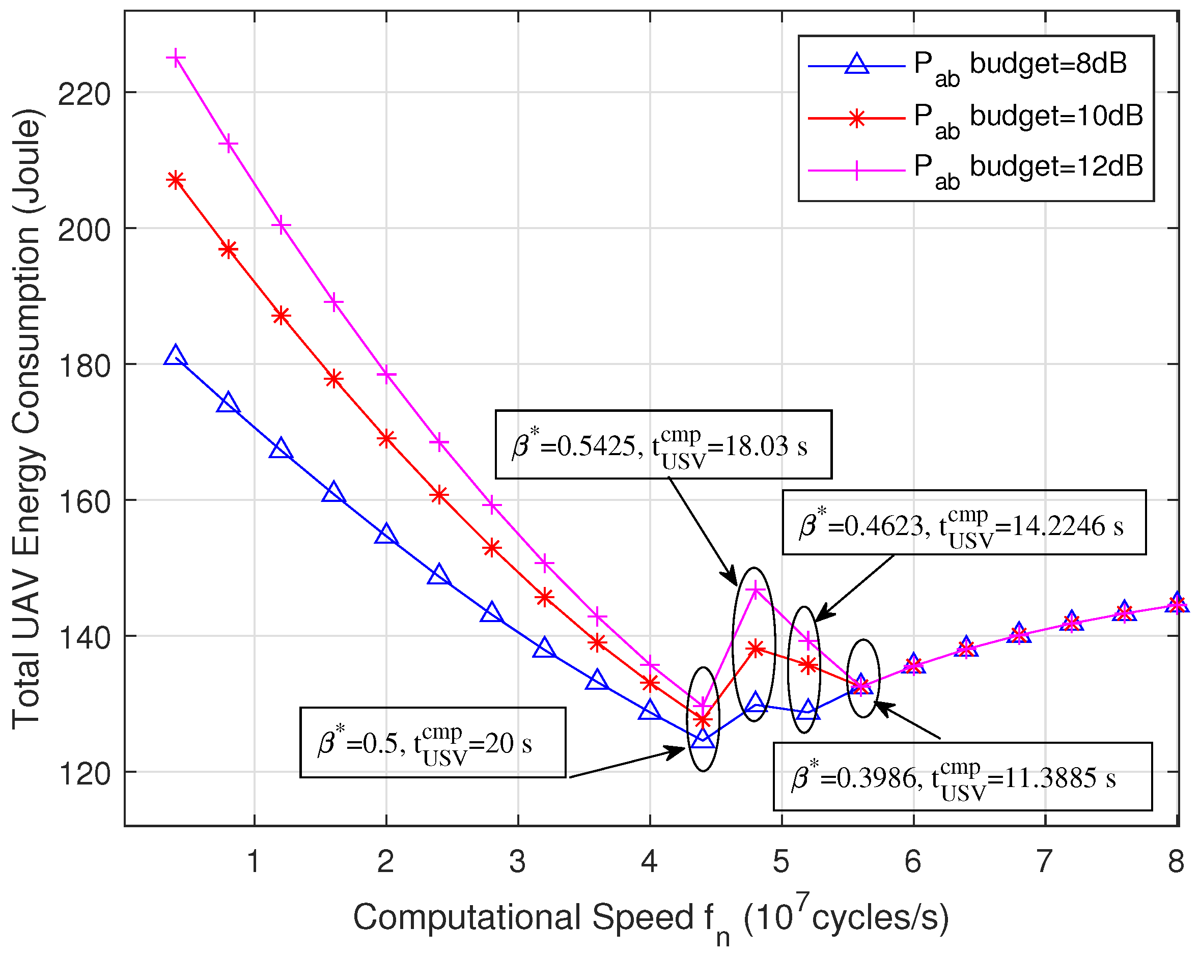
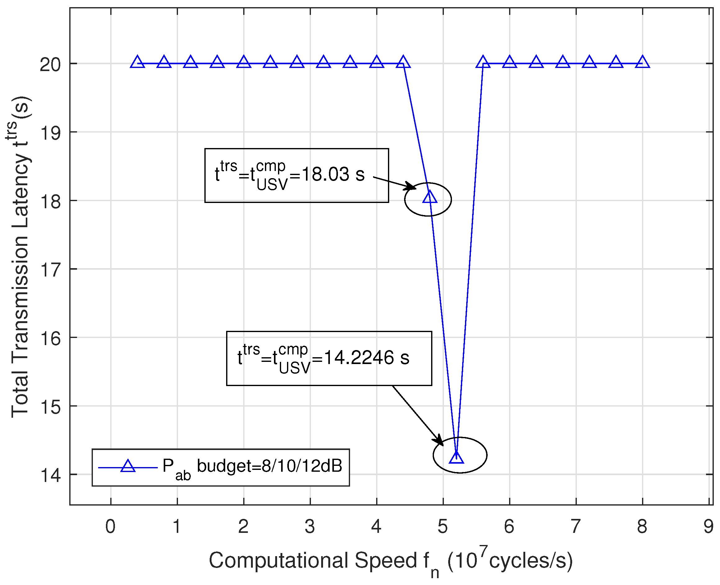
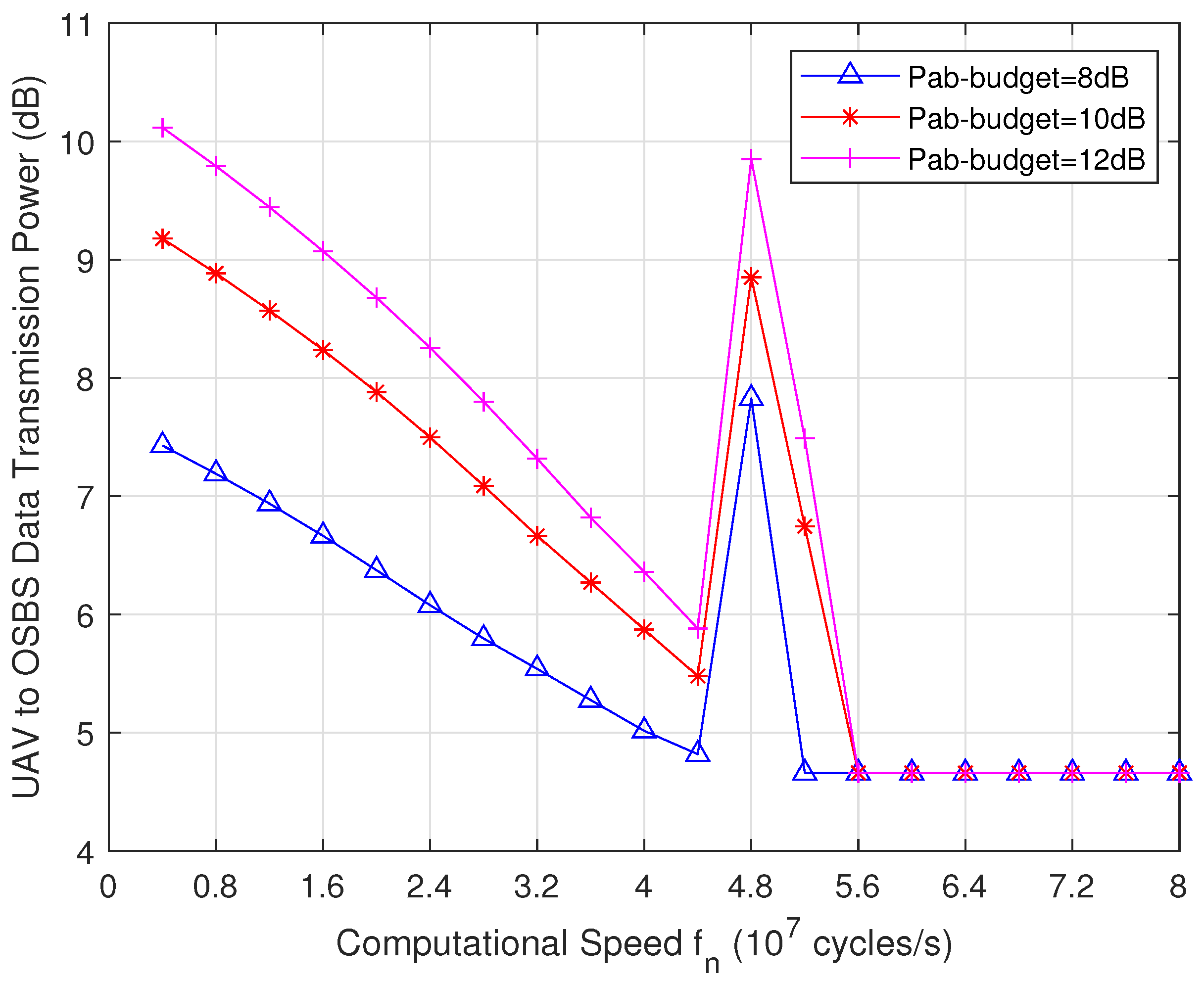
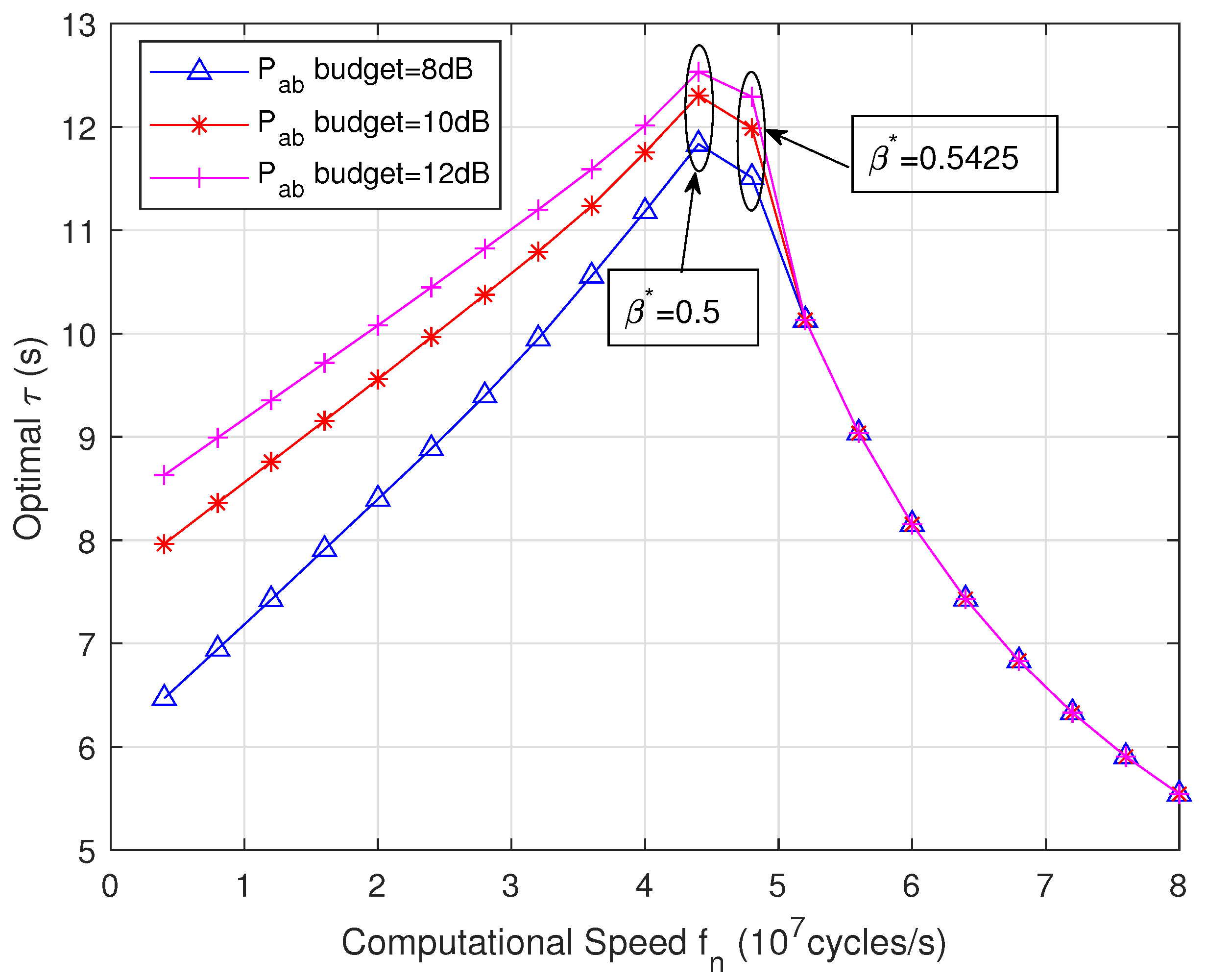
5.1. Proposed Strategy Performance for Different f n Values

We evaluated the effects of the proposed strategy on the total UAV energy consumption, UAV transmission power value, optimal computing ratio, and USV NOMA transmission latency by adjusting the local computing value speed f n . The total system latency constraint was set to 20 s. According to Equations (6) and (7), for a given system latency constraint T and a local computing energy budget E ¯ n c m p , the partial computation offloading ratio β n increases with increasing f n , which reduces the to-be-transmitted data volume for the nth USV. Moreover, a tradeoff exists between USV local computing latency t U S V c m p and computing energy consumption E U S V c m p with respect to f n .
Figure 2 and Figure 3 show the minimum total UAV energy consumption and its corresponding transmission latency t t r s for different USV local computational speeds f n for different UAV transmission power budgets. Figure 2 shows that the minimum total UAV energy consumed continuously decreases when f n 0.4 × 10 7 , 4.4 × 10 7 . In this f n region, a USV provides enough computing energy, i.e., E n c m p E ¯ n c m p , and the optimal partial computation offloading ratio β n * is determined by the system latency constraint T, which fits Case 2 in Equation (15). Therefore, the minimum E U A V t o t a l value continuously decreases as the total to-be-relayed data volume decreases until its computing energy fits the budget. When f n 4.4 × 10 7 , 5.6 × 10 7 , the optimal partial computation offloading ratio β n * is determined by the computing energy budget E ¯ n c m p , which suits Case 3 in Equation (15). More energy needs to be consumed by the UAV to support the transmission of more data, as shown by comparing β * = 0.5425 by f n = 4.8 × 10 7 with β * = 0.5 by f n = 4.4 × 10 7 (Figure 2). Furthermore, within region f n 4.8 × 10 7 , 5.2 × 10 7 , the total system latency is determined via parallel data computing t U S V c m p , as shown in Figure 3. More UAV transmission power is consumed to guarantee that the total transmission latency does not exceed its parallel data computing latency and results in more UAV energy consumption. This is demonstrated by the first increasing and then decreasing curve of the minimum E U A V t o t a l . When f n 5.6 × 10 7 , 8 × 10 7 , the total system latency is determined by the total transmission latency. Then, the minimum E U A V t o t a l value gradually grows to 144 Joules with decreasing optimal parallel data computing ratio β n * . Specifically, in this f n region, the minimum total UAV energy consumption is consistent with the different UAV transmission power budgets. This occurs is because the optimal τ and the optimal p a b * are identical, as shown in Figure 4 and Figure 5, respectively. When the transmission latency is equal to T, the minimum UAV energy consumption is only influenced by the t U A V t r s p a b part in Equation (12), whose optimal value is obtained by solving its equivalent problem F p a b . Therefore, optimal value p a b * can be obtained according to its closed-form solution in Equation (21) in Feasible area (29), which is not relevant to the given transmission power budget p ¯ A .
Figure 4 shows the optimal UAV transmission power gain for different USV local computational speeds f n for different UAV transmission power budgets. The changes in the optimal p a b * are consistent with those of E U A V t o t a l in Figure 2. When f n 0.4 × 10 7 , 4.4 × 10 7 , β n * is determined by the limited system latency constraint T. Thus, the optimal p a b * is obtained for the case in Section 4.2.1, which increases as the optimal β n * decreases. When f n 4.4 × 10 7 , 5.6 × 10 7 , the optimal p a b * increases to guarantee that the total transmission latency does not to exceed the total computing latency. When f n 5.6 × 10 7 , 8 × 10 7 , the total system latency is determined by the total transmission time; the optimal value p a b * can be obtained according to its closed-form solution with Equation (21) in Feasible area (29), which is not relevant for the given transmit power budget p ¯ A .
Figure 5 shows the minimum USV transmission time versus different USV local computational speeds f n for different UAV transmission budgets. The changes in the minimum USV transmission latency are consistent with the changes in E U A V t o t a l in Figure 2. Specifically, when f n 5.2 × 10 7 , 8 × 10 7 , the minimum USV NOMA transmission latency is consistent with the different UAV power budgets because it is obtained iteratively using an iterative p a b , which agrees with what is shown in Figure 4.

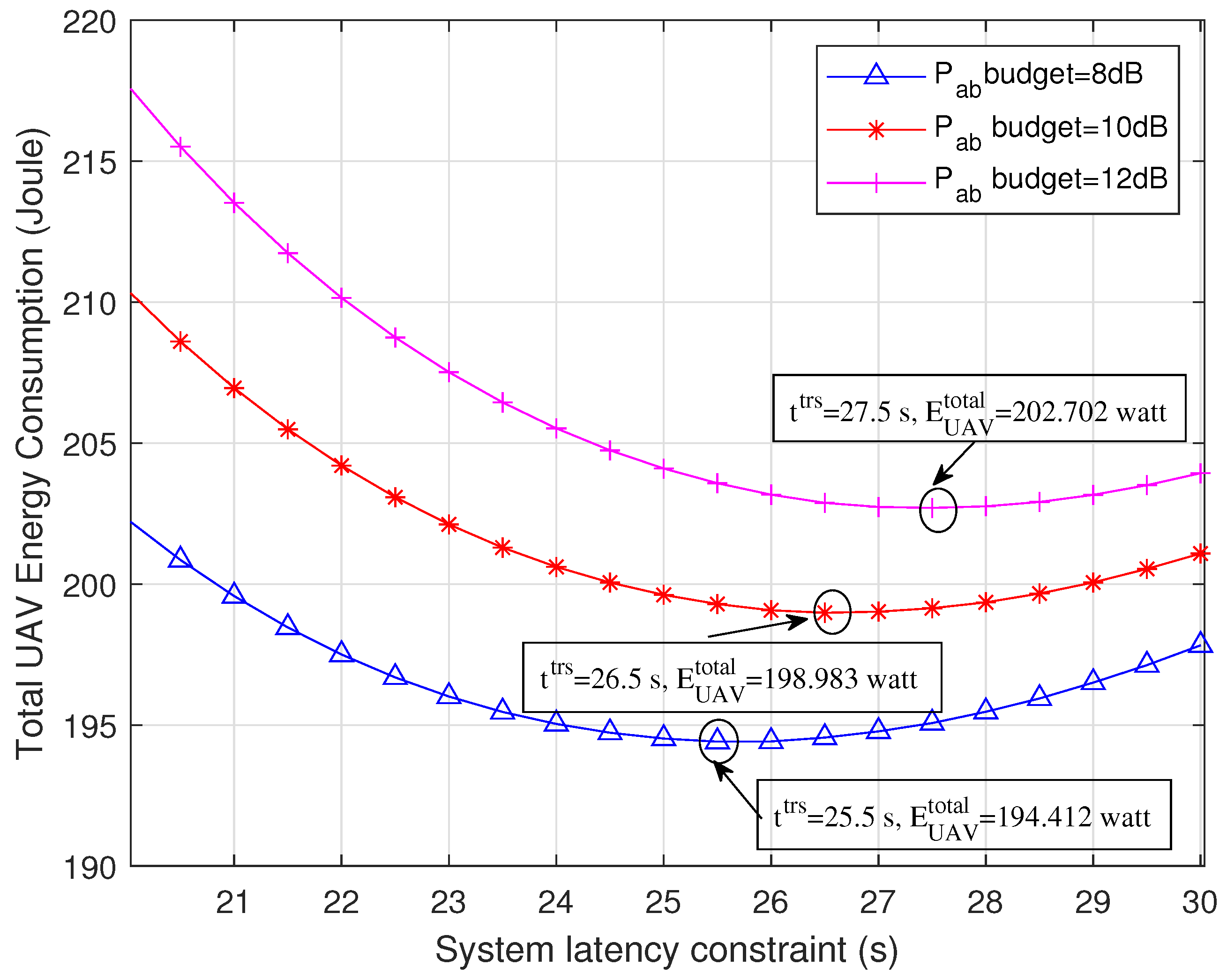
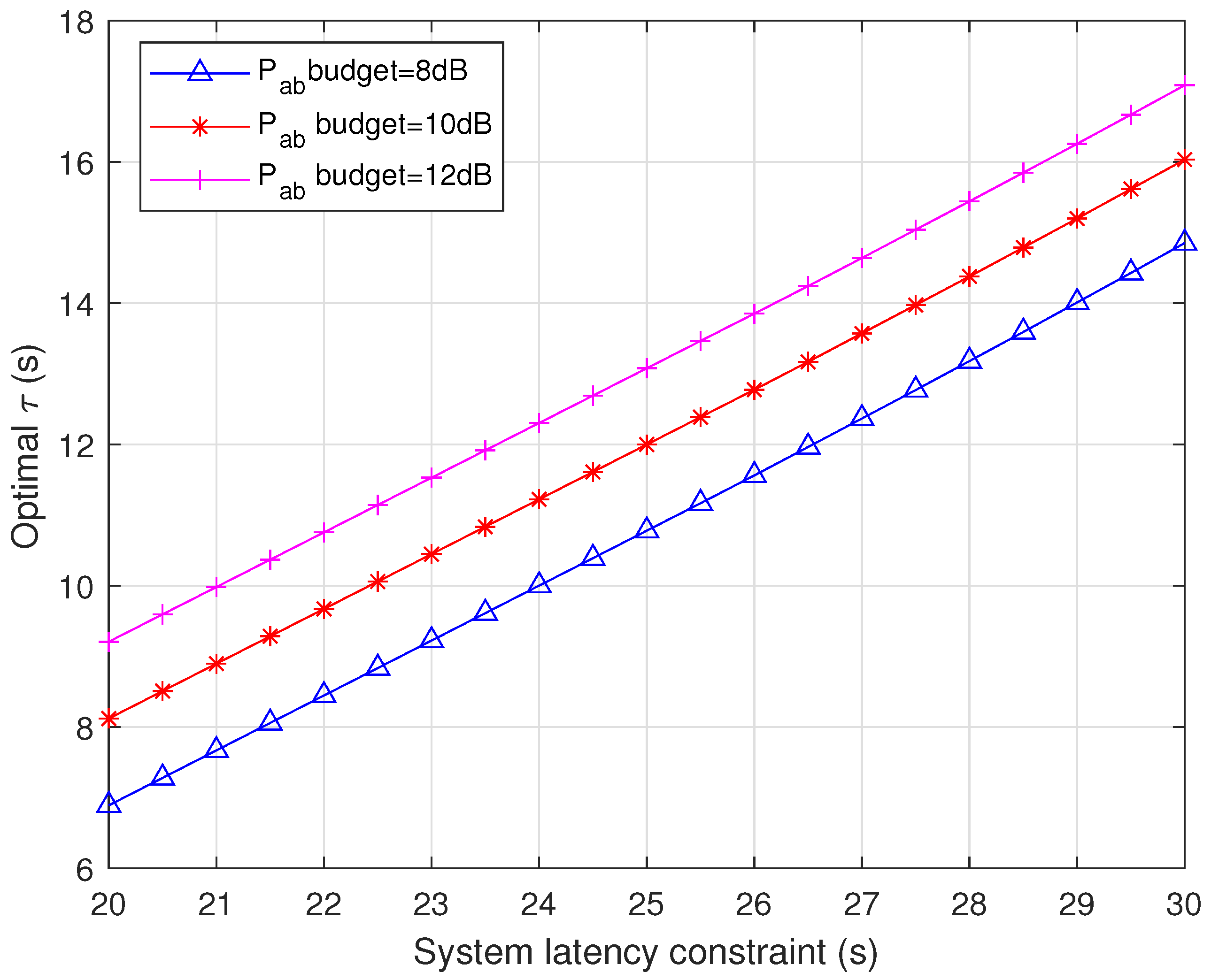
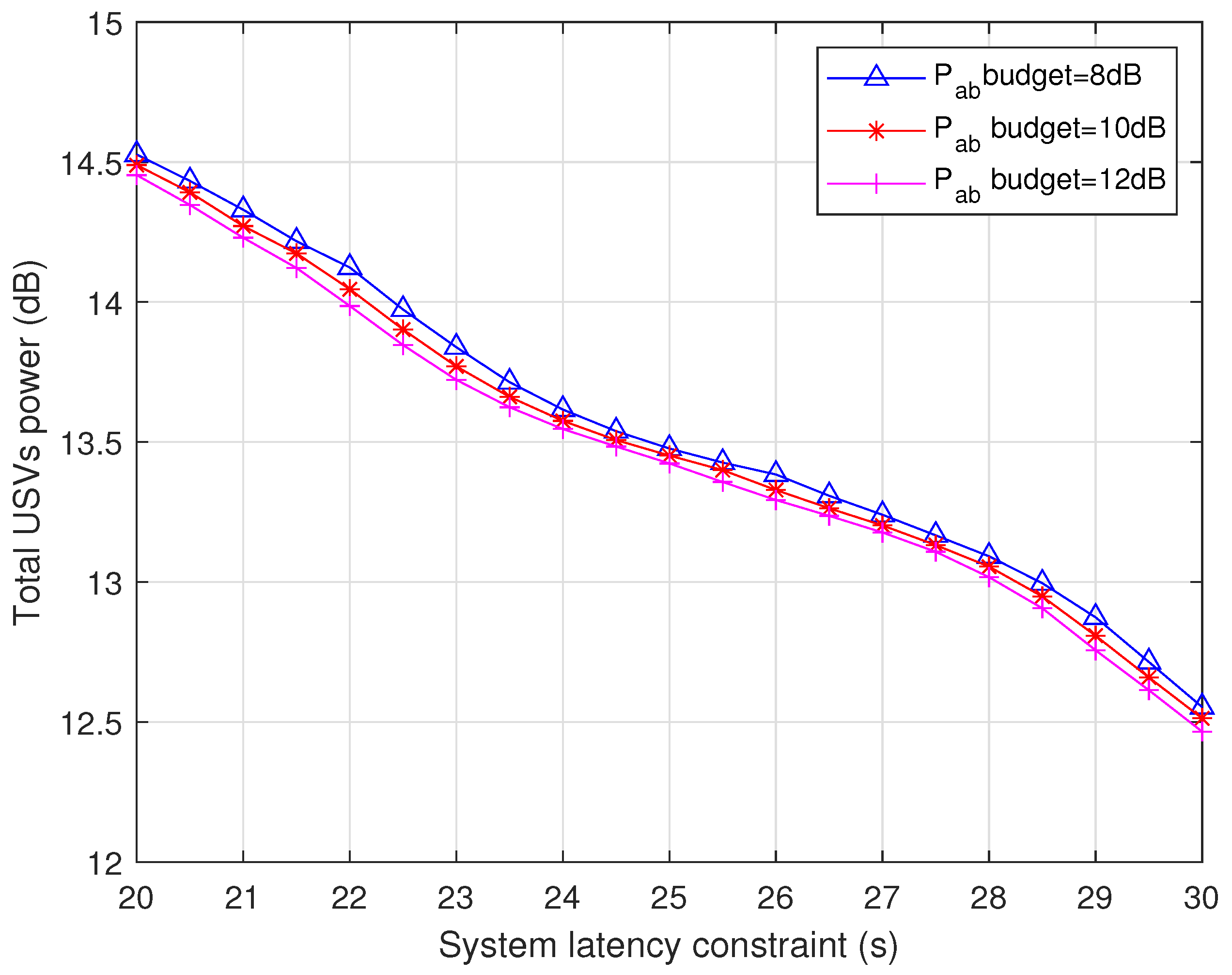
5.2. Proposed Strategy Performance for Different T Values

We evaluated the performance of the proposed strategy by adjusting the system latency constraint T. In this part, the USV computational speed was set to f n = 1 × 10 7 cycles/s, which was enough to support a USV to finish computing its data received from the UWSs if only considering its computing energy budget set using E ¯ n c m p = 20 mWatt. Thus, the optimal partial computational offloading ratio β * was only determined by system latency constraint T. Because the optimal ratio β * is never larger than one, the system total latency is determined by the USV computing latency, which is equal to the system latency constraint T.
Figure 6 shows the minimum total UAV energy consumption versus system latency constraint T for different UAV transmit power budgets. With an increasing system latency constraint, the minimum total UAV energy consumption first quickly reduces before arriving at a minimum; then, it slightly grows. This occurs because a higher optimal partial computation offloading ratio β * can be obtained by increasing the USV computing latency, which decreases the to-be-transmitted data volume and lowers the UAV transmission power. However, longer computing latency increases the UAV hovering time, which results in the UAV consuming more energy to hover. Thus, when the total system latency is determined by the local computing latency, a tradeoff exists between the local partial computation offloading ratio β * and the total UAV energy consumption. Moreover, in the partial computation determined latency scenario, by adjusting the system latency constraints, the minimum E U A V t o t a l can be reached at the labeled points in Figure 6.
Accordingly, for the corresponding performance with an optimal τ , the total USV data transmission power and optimal UAV transmission power are shown in Figure 7, Figure 8 and Figure 9, respectively. By increasing the system latency constraint, the optimal USVs data transmission latency rises, whereas the total USV and UAV transmission powers both decrease. That is, more transmission power can be saved at the cost of longer transmission latency.

5.3. Performance Comparison

We compared the performance of the proposed strategy with that of other benchmarks. Given the special characteristics of the proposed marine data collection scenario, we considered a full offloading method (FO) [20] and random offloading and resource allocation method (RORA) as the benchmarks. RORA is a method that uses partial offloading and random power allocation with constraints including system resource budgets. The system latency constraint was T = 20 s. The computational speed was set to f n = 1 × 10 7 cycles/s. Figure 10 compares the energy efficiency performance of our proposed strategy with that of the benchmarks for different numbers of USVs. Our strategy outperformed the benchmarks in terms of aerial relay node energy consumption. FO consumed the most energy among the three methods for our considered system, reaching a peak of 380.812 Joules for seven USVs, because all data collected from the UWSs were relayed by the UAV without the partial offloading supported by the USVs.

6. Conclusions

In this study, an MEC-assisted marine data collection system was constructed, in which UAV data relay and several MEC-enabled USVs are deployed to relay the data collected from UWSs to OSBS. Specifically, due to the limitations in terms of the spectrum and energy resources in marine communication environments, the original data from UWSs are partially computed in a set of MEC-enabled USVs before being relayed. A UAV acts as an aerial relay node for sending the remaining data from the USVs to the OSBS. The NOMA transmission scheme is adopted to transmit data from the USVs to the UAV. To prolong the lifetime of the UAV relay node, a UAV energy consumption minimization problem was developed, constrained by USV computational ability, USV transmission power budget, UAV transmission power budget, and system latency. To address this problem, an energy optimal parallel partial computing and relay strategy was designed by jointly optimizing the partial computation offloading ratio, USV transmission power allocation, and UAV transmission power. Finally, numerical results verified the effectiveness of the proposed strategy, and the results revealed the effects of local computing capabilities and system resource allocation on reducing UAV relay energy consumption and system latency.
Although the effectiveness of the proposed strategy was verified by the simulation results, it has some limitations. One of the main challenges is the limited service capability of a UAV when relaying large-scale marine container data, as these containers are sparsely distributed on the sea surface. Additionally, advanced techniques, such as reconfigurable intelligent surface sand rate-splitting multiple access, can be used to enhance system performance of marine communication networks [29,30,31]. Thus, future research could focus on resource optimization in collaborative MIoT systems with multiple aerial nodes.

Author Contributions

Conceptualization, W.X.; methodology, W.X.; software, W.X.; validation, W.X.; formal analysis, W.X.; investigation, W.X.; resources, W.X.; data curation, W.X.; writing—original draft preparation, W.X.; writing—review and editing, W.X. and L.G.; supervision, W.X.; project administration, W.X.; funding acquisition, W.X. All authors have read and agreed to the published version of the manuscript.

Funding

This research was funded by the Shanghai Sailing Program, grant number 20YF1416700; Innovation Program of Shanghai Municipal Education Commission of China under Grant 2021-01-07-00-10-E00121; the National Natural Science Foundation of China (62271303); Shanghai Rising-Star Program, grant number 22YF1416100.

Institutional Review Board Statement

Not applicable.

Informed Consent Statement

Not applicable.

Data Availability Statement

Data are contained within the article.

Acknowledgments

The authors are grateful to the anonymous reviewers for their constructive comments that have improved the presentation of this paper significantly.

Conflicts of Interest

The authors declare no conflict of interest.

References

  1. Wang, M.M.; Zhang, J.; You, X. Machine-type communication for maritime Internet of Things: A design. IEEE Commun. Surv. Tutor. 2020, 22, 2550–2585. [Google Scholar] [CrossRef]
  2. Jiang, S.M. Networking in oceans: A Survey. ACM Comput. Surv. 2020, 54, 33. [Google Scholar] [CrossRef]
  3. Kim, M.; Lee, S.; Park, C.; Lee, J.; Saad, W. Ensuring data freshness for blockchain-enabled monitoring networks. IEEE Internet Things J. 2022, 9, 9775–9788. [Google Scholar] [CrossRef]
  4. Abedin, S.F.; Munir, M.S.; Tran, N.H.; Han, Z.; Hong, C.S. Data freshness and energy-efffcient UAV navigation optimization: A deep reinforcement learning approach. IEEE Trans. Intell. Transp. Syst. 2021, 22, 5994–6006. [Google Scholar] [CrossRef]
  5. Wang, D.; Wu, M.; Wei, Z.; Yu, K.; Min, L.; Mumtaz, S. Uplink secrecy performance of RIS-based RF/FSO three-dimension heterogeneous networks. IEEE Trans. Wirel. Commun. 2023, 99, 1. [Google Scholar] [CrossRef]
  6. Wang, D.; He, T.; Zhou, F.; Cheng, J.; Zhang, R.; Wu, Q. Outage-driven link selection for secure buffer-aided networks. Sci. China Inf. Sci. 2022, 65, 182303. [Google Scholar] [CrossRef]
  7. Seid, A.M.; Boateng, G.O.; Anokye, S.; Kwantwi, T.; Sun, G.; Liu, G. Collaborative computation offloading and resource allocation in multi-UAV-assisted IoT networks: A deep reinforcement learning approach. IEEE Internet Things J. 2021, 8, 12203–12218. [Google Scholar] [CrossRef]
  8. Guo, H.; Liu, J. UAV-enhanced intelligent offloading for internet of things at the edge. IEEE Trans. Ind. Inf. 2020, 16, 2737–2746. [Google Scholar] [CrossRef]
  9. Yang, T.; Feng, H.; Gao, S.; Jiang, Z.; Qui, M.; Cheng, N. Two-Stage offfoading optimization for energy–latency tradeoff with mobile edge computing in maritime internet of things. IEEE Internet Things J. 2020, 7, 5954–5963. [Google Scholar] [CrossRef]
  10. Dai, Y.; Lin, B.; Che, Y.; Lyu, L. UAV-assisted data offloading for smart container in offshore maritime communications. China Commun. 2022, 19, 153–165. [Google Scholar] [CrossRef]
  11. Qian, L.P.; Zhang, H.; Wang, Q.; Wu, Y.; Lin, B. Joint multi-domain resource allocation and trajectory optimization in UAV-assisted maritime IoT networks. IEEE Internet Things J. 2023, 10, 539–552. [Google Scholar] [CrossRef]
  12. Xu, W.; Tian, J.; Gu, L.; Tao, S. Joint placement and power optimization of UAV-relay in NOMA enabled maritime IoT system. Drones 2022, 6, 304. [Google Scholar] [CrossRef]
  13. Wang, D.; Zhou, F.; Lin, W.; Ding, Z.; Al-Dhahir, N. Cooperative Hybrid Nonorthogonal Multiple Access-Based Mobile-Edge Computing in Cognitive Radio Networks. IEEE Trans. Cogn. Commun. Netw. 2022, 8, 1104–1117. [Google Scholar] [CrossRef]
  14. Liu, B.; Liu, C.; Peng, M. Resource allocation for energy-efficient MEC in NOMA-enabled aassive IoT networks. IEEE J. Sel. Areas Commun. 2021, 39, 1015–1027. [Google Scholar] [CrossRef]
  15. Ding, Z.; Xu, J.; Dobre, O.A.; Poor, H.V. Joint power and time allocation for NOMA–MEC offloading. IEEE Trans. Veh. Technol. 2019, 68, 6207–6211. [Google Scholar] [CrossRef]
  16. Tripathi, S.; Pandey, O.J.; Cenkeramaddi, L.R.; Hegde, R.M. A socially-aware radio map framework for improving QoS of UAV-assisted MEC networks. IEEE Trans. Netw. Serv. Manag. 2023, 20, 342–356. [Google Scholar] [CrossRef]
  17. Park, Y.M.; Hassan, S.S.; Tun, Y.K.; Han, Z.; Hong, C.S. Joint trajectory and resource optimization of MEC-assisted UAVs in Sub-THz networks: A resources-based multi-agent proximal policy optimization DRL with attention mechanism. arXiv 2023, arXiv:2209.07228. [Google Scholar] [CrossRef]
  18. Nguyen, L.X.; Tun, Y.K.; Dang, Y.M.; Park, Z.H.; Hong, C.S. Dependency Tasks Offloading and Communication Resource Allocation in Collaborative UAV Networks: A Metaheuristic Approach. IEEE Internet Things J. 2023, 10, 9062–9076. [Google Scholar] [CrossRef]
  19. Lakew, D.S.; Tran, A.-T.; Dao, N.-N.; Cho, S. Intelligent offloading and resource allocation in heterogeneous aerial access IoT networks. IEEE Internet Things J. 2023, 10, 5704–5718. [Google Scholar] [CrossRef]
  20. Tri-Hai, N.; Laihyuk, P. HAP-assisted RSMA-enabled vehicular edge computing: A DRL-based optimization Framework. Mathematics 2023, 11, 2376. [Google Scholar]
  21. Truong, T.P.; Dao, N.-N.; Cho, S. HAMEC-RSMA: Enhanced aAerial computing systems with rate splitting multiple access. IEEE Access 2022, 10, 52398–52409. [Google Scholar] [CrossRef]
  22. Nasir, A.A.; Tuan, H.D.; Duong, T.Q.; Poor, H.V. UAV-enabled communication using NOMA. IEEE Trans. Commun. 2019, 67, 5126–5138. [Google Scholar] [CrossRef]
  23. Matolak, D.W.; Sun, R. Air-ground channel characterization for unmanned aircraft systems—Part I: Methods, measurements, and models for over-water settingse. IEEE Trans. Veh. Technol. 2017, 66, 26–44. [Google Scholar] [CrossRef]
  24. Sardellitti, S.; Scutari, G.; Barbarossa, S. Joint optimization of radio and computational resources for multicell mobile-edge computing. IEEE Trans. Signal Inf. Process. Over Netw. 2015, 1, 89–103. [Google Scholar] [CrossRef]
  25. Munoz, O.; Pascual-Iserte, A.; Vidal, J. Optimization of radio and computational resources for energy efficiency in latency-constrained application offloading. IEEE Trans. Veh. Technol. 2015, 64, 4738–4755. [Google Scholar] [CrossRef]
  26. Zhang, W.; Wen, Y.; Guan, K.; Kilper, D.; Luo, H.; Wu, D.O. Energy-optimal mobile cloud computing under stochastic wireless channel. IEEE Trans. Commun. 2013, 12, 4569–4581. [Google Scholar] [CrossRef]
  27. Wang, Y.; Sheng, M.; Wang, X.; Wang, L.; Li, J. Mobile-edge computing: Partial computation offloading using dynamic voltage scaling. IEEE Trans. Commun. 2016, 64, 4268–4282. [Google Scholar] [CrossRef]
  28. Boyd, S.; Vandenberghe, L. Convex Optimization; Cambridge University Press: Cambridge, UK, 2004. [Google Scholar]
  29. Truong, T.P.; Tuong, V.D.; Dao, N.-N.; Cho, S. FlyReflect: Joint Flying IRS Trajectory and Phase Shift Design Using Deep Reinforcement Learning. IEEE Internet Things J. 2023, 10, 4605–4620. [Google Scholar] [CrossRef]
  30. Hua, D.-T.; Do, Q.T.; Dao, N.-N.; Nguyen, T.-V.; Shumeye Lakew, D.; Cho, S. Learning-Based Reconfigurable-Intelligent-Surface-Aided Rate-Splitting Multiple Access Networks. IEEE Internet Things J. 2023, 10, 17603–17619. [Google Scholar] [CrossRef]
  31. Nguyen, T.-H.; Nguyen, L.V.; Dang, L.M.; Hoang, V.T.; Park, L. TD3-Based Optimization Framework for RSMA-Enhanced UAV-Aided Downlink Communications in Remote Areas. Remote Sens. 2023, 15, 5284. [Google Scholar] [CrossRef]
Figure 1. UAV-assisted marine data collection network.
Jmse 11 02333 g001
Figure 2. The minimum E U A V t o t a l versus f n under different UAV transmission budgets. The system latency constraint T = 20 s.
Jmse 11 02333 g002
Figure 3. The total transmission latency t t r s versus f n under different UAV transmission budgets. The system latency constraint T = 20 s.
Jmse 11 02333 g003
Figure 4. The minimum UAV data transmit power gains versus f n under different p a b budgets. The system latency constraint T = 20 s.
Jmse 11 02333 g004
Figure 5. The minimum USV data transmission latency versus f n under different p a b budgets. The system latency constraint T = 20 s.
Jmse 11 02333 g005
Figure 6. The minimum UAV total energy consumption versus latency constraint T under different p a b budgets. Computational speed is set to f n = 1 × 10 7 cycles/s.
Jmse 11 02333 g006
Figure 7. The minimum τ v.s. system latency constraint T. Computational speed is set to f n = 1 × 10 7 cycles/s.
Jmse 11 02333 g007
Figure 8. The corresponding USVs total transmit power n N p n v.s. system latency constraint T. Computational speed is set to f n = 1 × 10 7 cycles/s.
Jmse 11 02333 g008
Figure 9. The corresponding optimal UAV transmit power p a b v.s. system latency constraint T. Computational speed is set to f n = 1 × 10 7 cycles/s.
Jmse 11 02333 g009
Figure 10. The energy efficiency performance comparison versus the number of USVs.
Jmse 11 02333 g010
Table 1. Comparison of related works and our work.
Refs.ScenariosUAV FunctionsTechniquesMetrics
[7]TerrestrialBS and computingFull offloadingTask executive delay
[8]TerrestrialRelay and computingFull offloadingEnergy efficiency
[9,10]MarineRelay and computingPartial offloadingSystem latency
[12]MarineRelayno MECEnergy efficiency
[16,17,18,19,20]TerrestrialRelay and computingFull offloadingRate and latency
[21]TerrestrialBS & computingPartial offloadingRate and task success rate
OursMarineRelayPartial offloadingUAV life time
Table 2. Notations used in the system model and problem formulation.
NotationDescription
n , N , N Index, the number, and the set of USVs
( x n , y n , 0 ) Coordinates of the nth USV
( x a , y a , z a ) Coordinates of the UAV
( x b , y b , z b ) Coordinates of the OSBS
d n a Distance between the nth USV and the UAV
d a b Distance between the UAV and the OSBS
h n a Channel gain from the nth USV to the UAV
h ˜ n a Rician fading component of h n a
L n a Large-scale fading coefficient of h n a
A n a , ζ n a , X n a Parameters of L n a
h a b Channel gain from the UAV to the OSBS
h ˜ a b Rician fading component of h a b
A a b , ζ a b , X a b Parameters of h a b ’s large-scale fading coefficient
d 0 Reference distance
f n , κ n Computing speed and a coefficient at the nth USV
r n , C n Data volume received at the nth USV and its computing cycles
α Computational multiplied factor
β n Partial computational offloading ratio of the nth USV
t n c m p , t U S V c m p Computing latency at the nth USV
t U S V c m p Overall computing latency of USVs
t U S V t r s , t U A V t r s Transmission latency from USVs-to-UAV and UAV-to-OSBS
p n , p a b Transmit power of the nth USV and the UAV
p h o v Hovering power value of the UAV
E n c m p , E ¯ n c m p Computing energy consumed at the nth USV and its budget
E n t r s , E U A V t r s Transmit energy consumed at the nth USV and the UAV
p ¯ n , p ¯ a b Transmit power budgets of the nth USV and the UAV
TSystem latency requirement
B a , N a Bandwidth and background noise of NOMA links
B b , N b Bandwidth and background noise of UAV-to-OSBS
Table 3. Marine communication environment parameters.
ParameterDescriptionValue
x b , y b , z b Coordination of onshore BS 0 , 200 , 50 m
x a , y a , z a Coordination of UAV hovering position 0 , 0 , 50 m
d 0 Reference distance1 m
B a Carrier frequency from USVs to UAV50 MHz
B b Carrier frequency from UAV to OSBS100 MHz
σ 2 Background noise 174 dBm
A n a A2S link path loss at  d 0 116.7
ς n a A2S link path loss exponent20
δ X n a Standard deviation of  X U 0.1
S n a A2S link Rician factor40
A a b A2A link path loss at  d 0 46.4
ς a b A2A link path loss exponent15
δ X a b standard deviation of  X U B 0.1
S a b A2A link Rician factor10
Disclaimer/Publisher’s Note: The statements, opinions and data contained in all publications are solely those of the individual author(s) and contributor(s) and not of MDPI and/or the editor(s). MDPI and/or the editor(s) disclaim responsibility for any injury to people or property resulting from any ideas, methods, instructions or products referred to in the content.

