


A Composite Super-Twisting Sliding Mode Approach for Platform Motion Suppression and Power Regulation of Floating Offshore Wind Turbine


Abstract
:1. Introduction
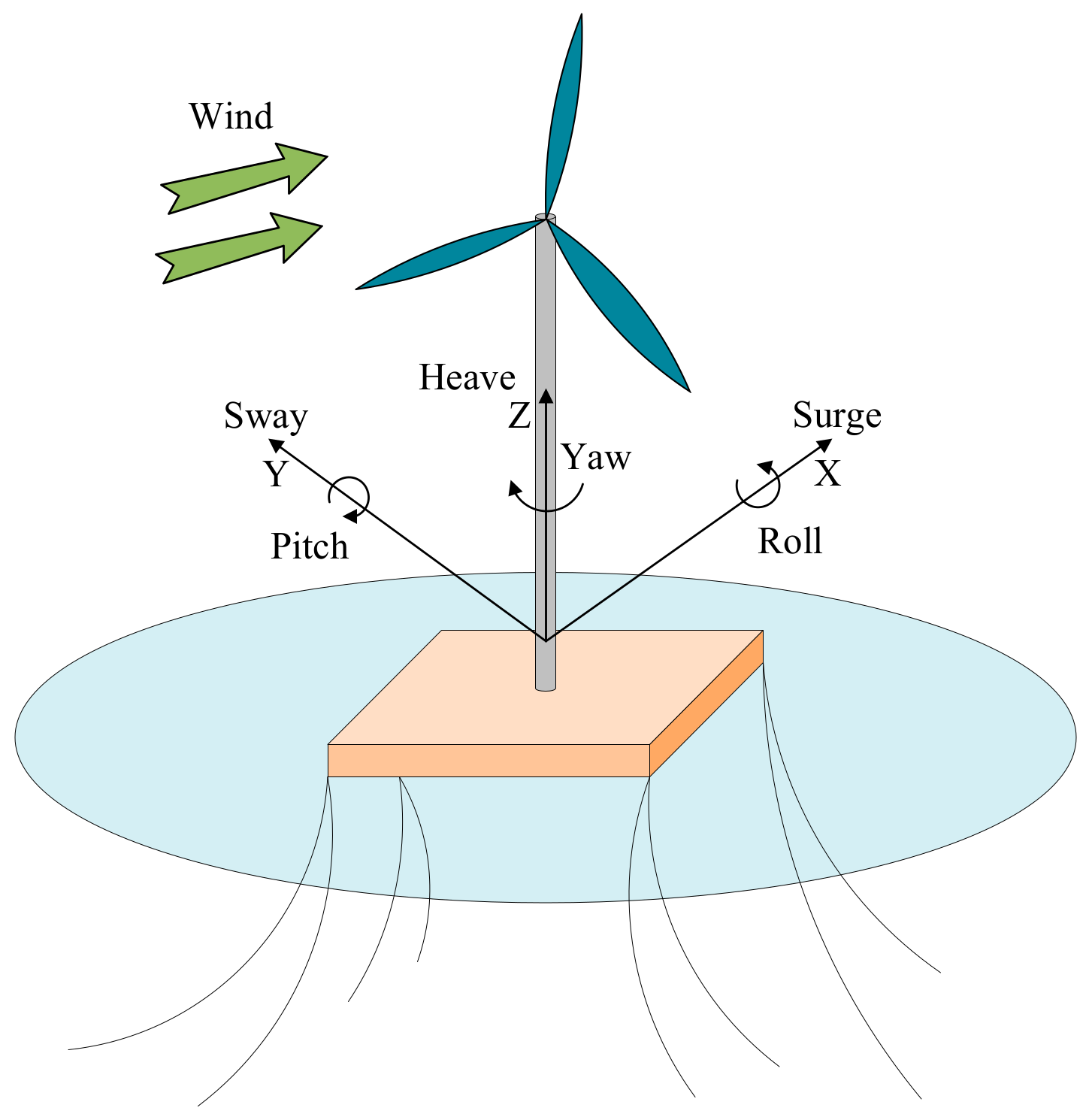
2. FOWT Model
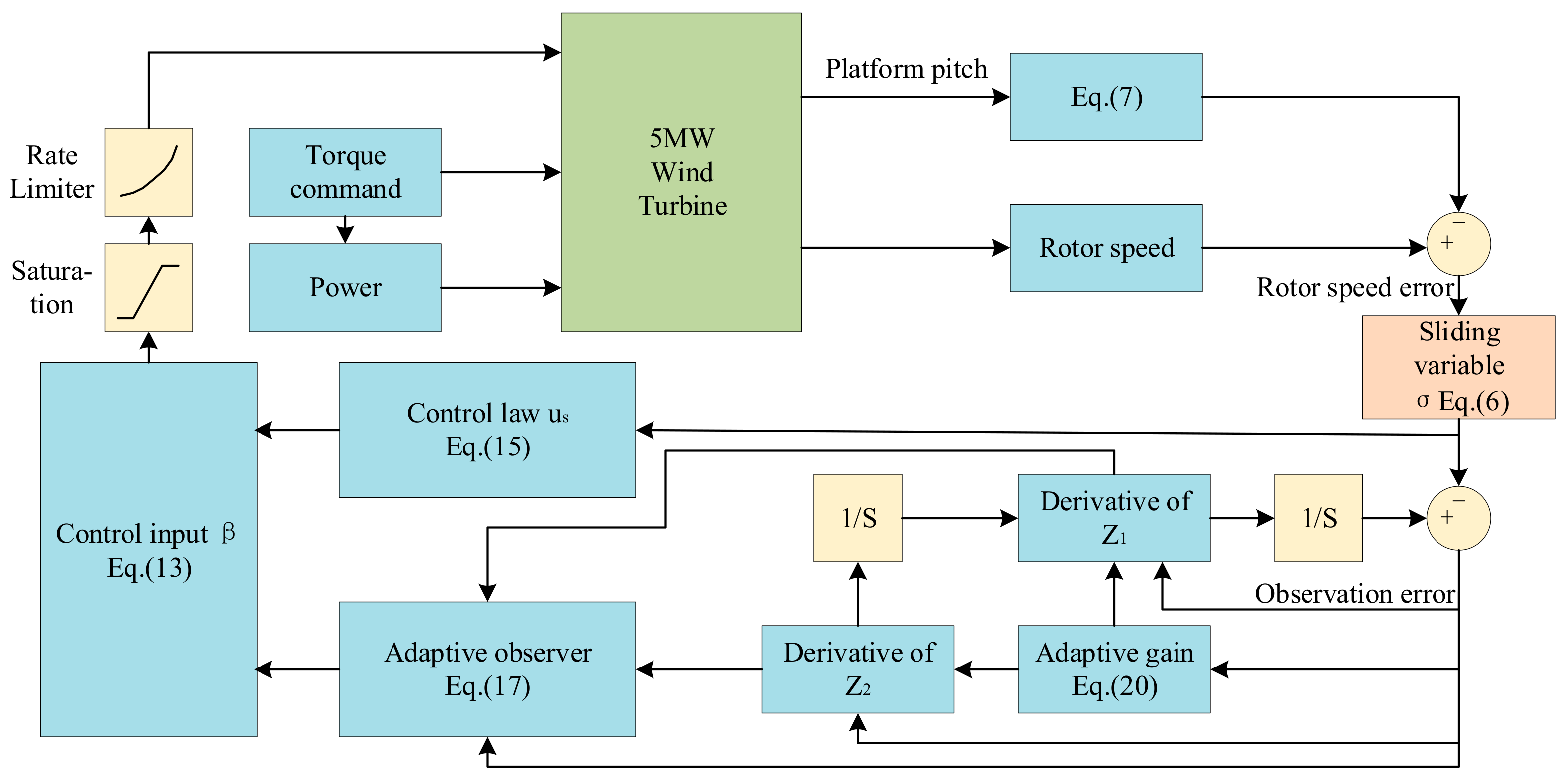
3. Control Scheme
4. Simulation Results and Discussion
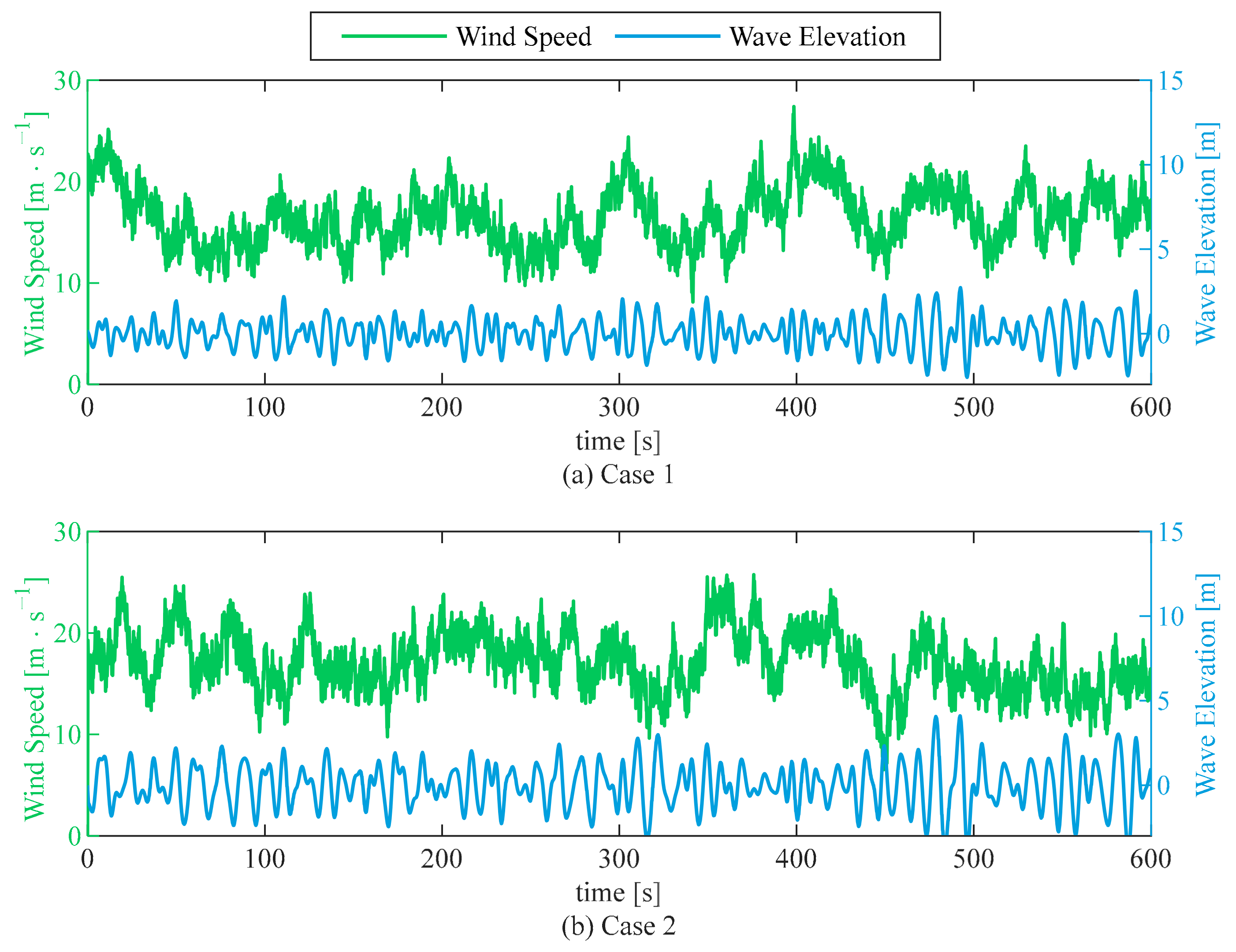
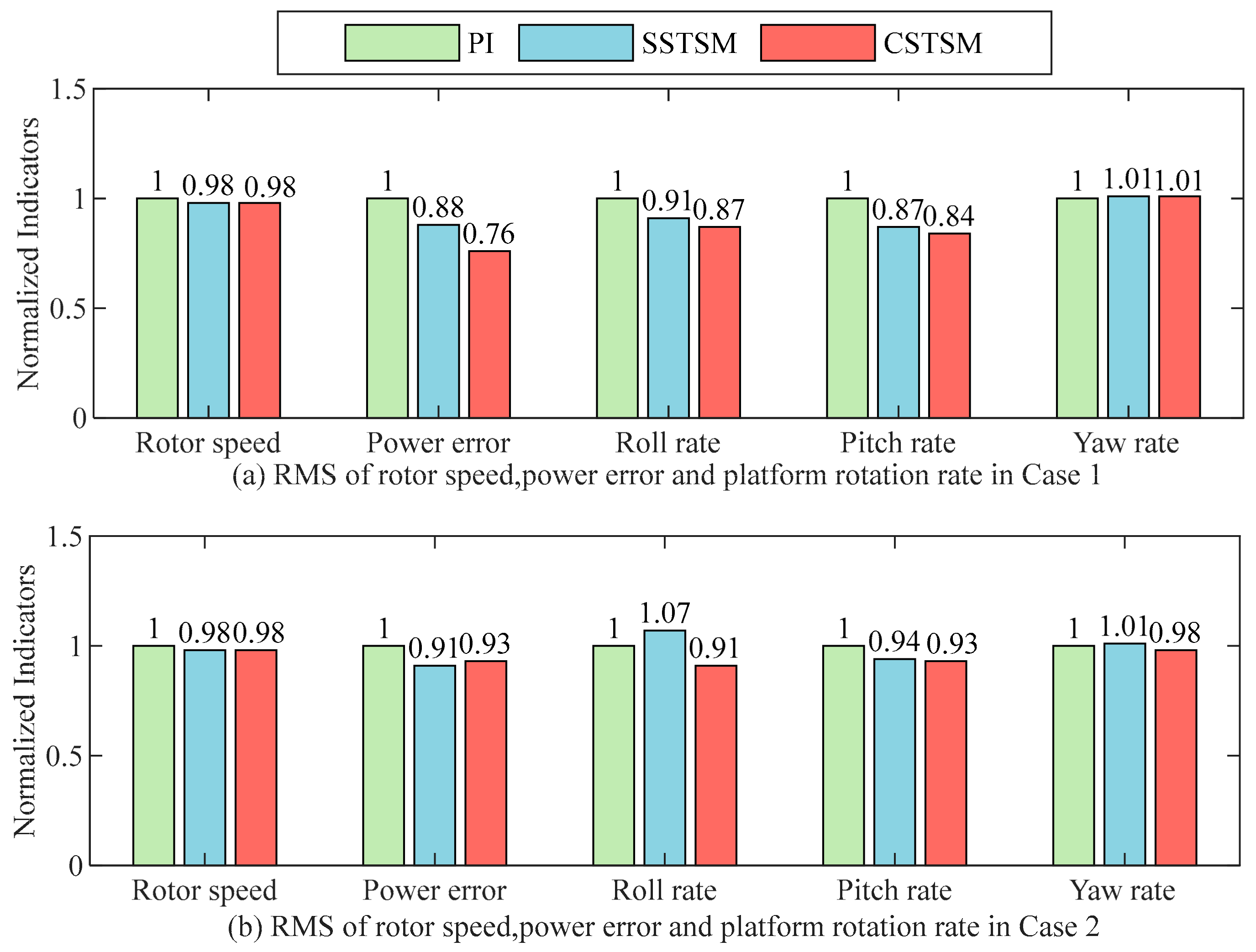
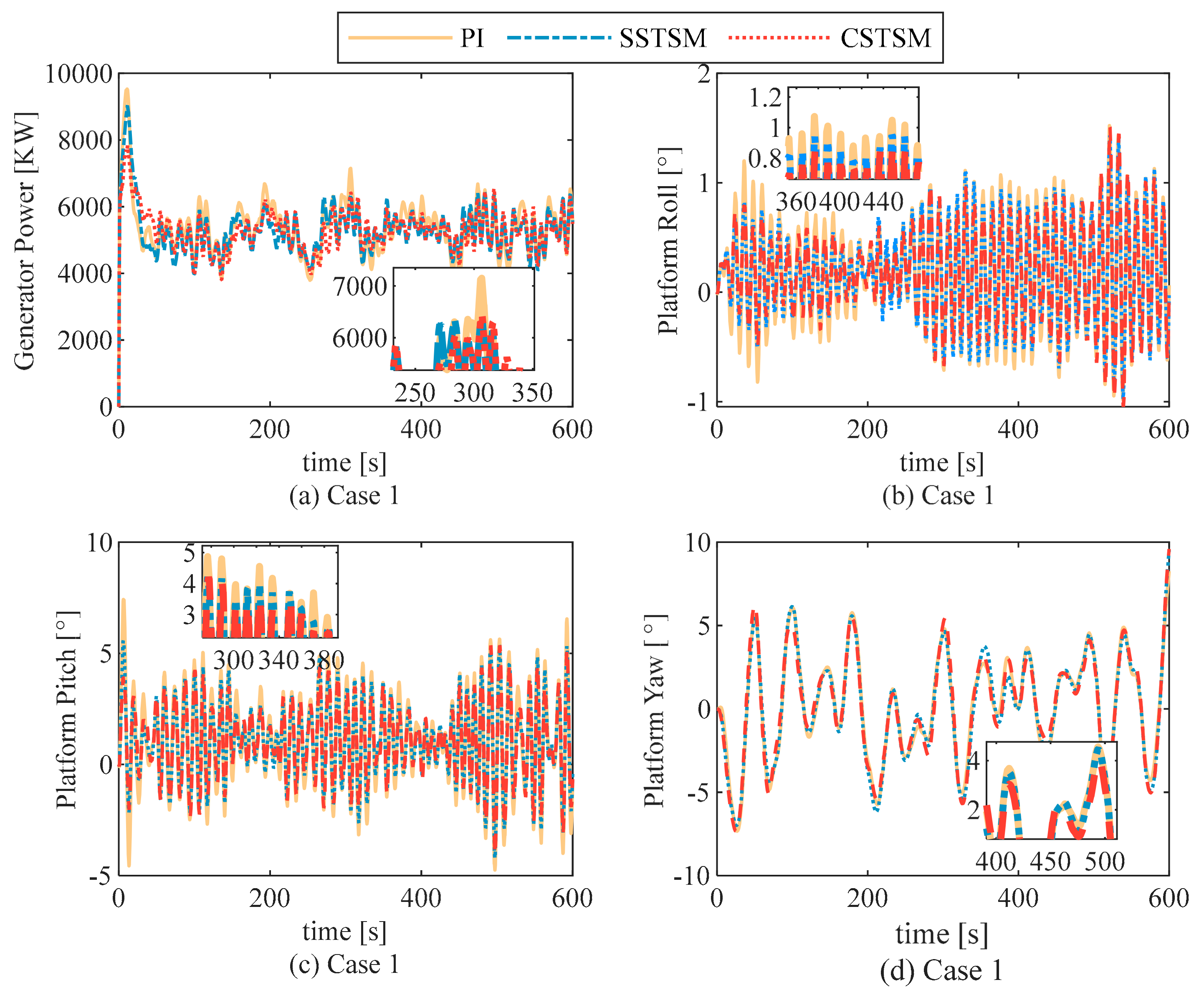
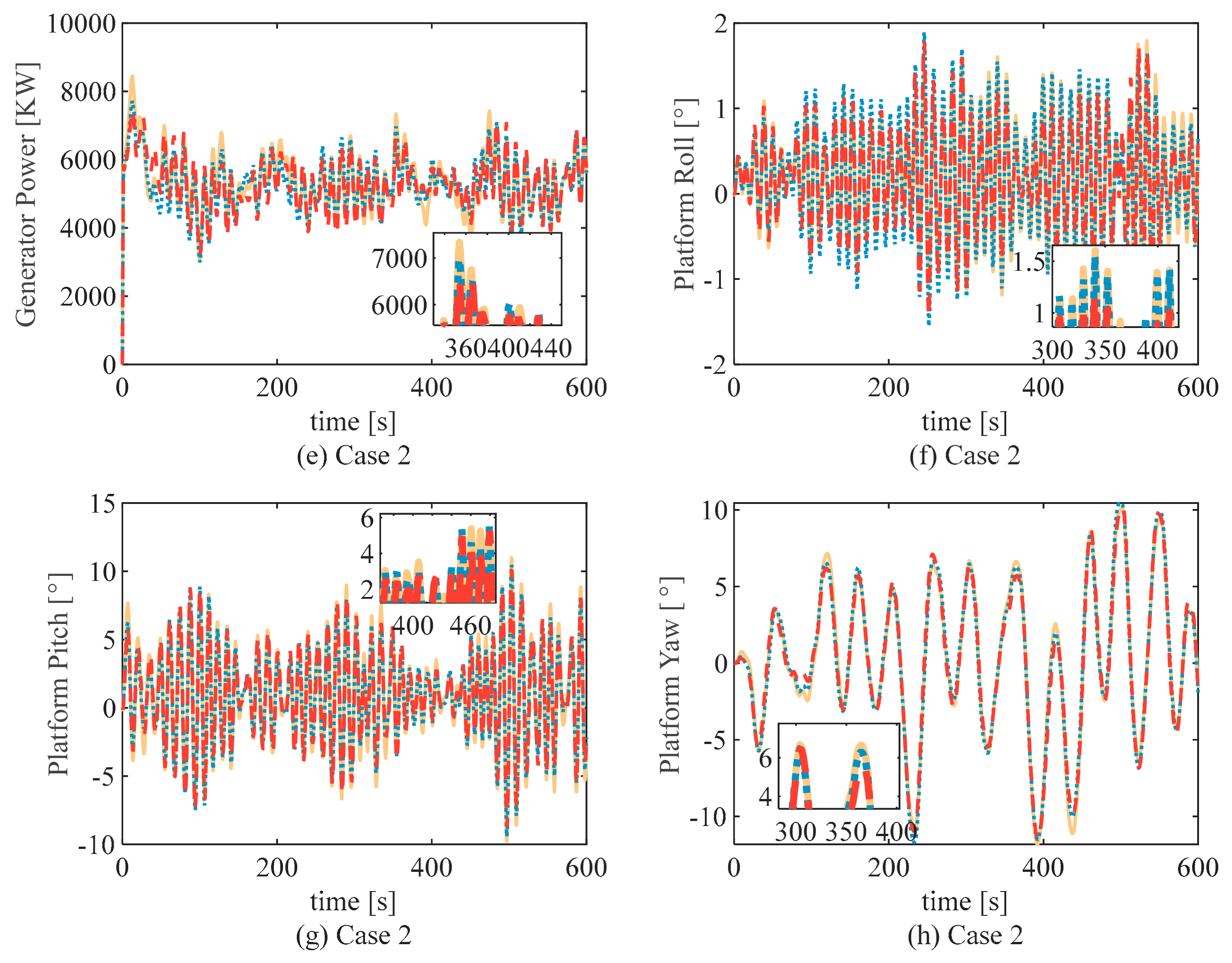
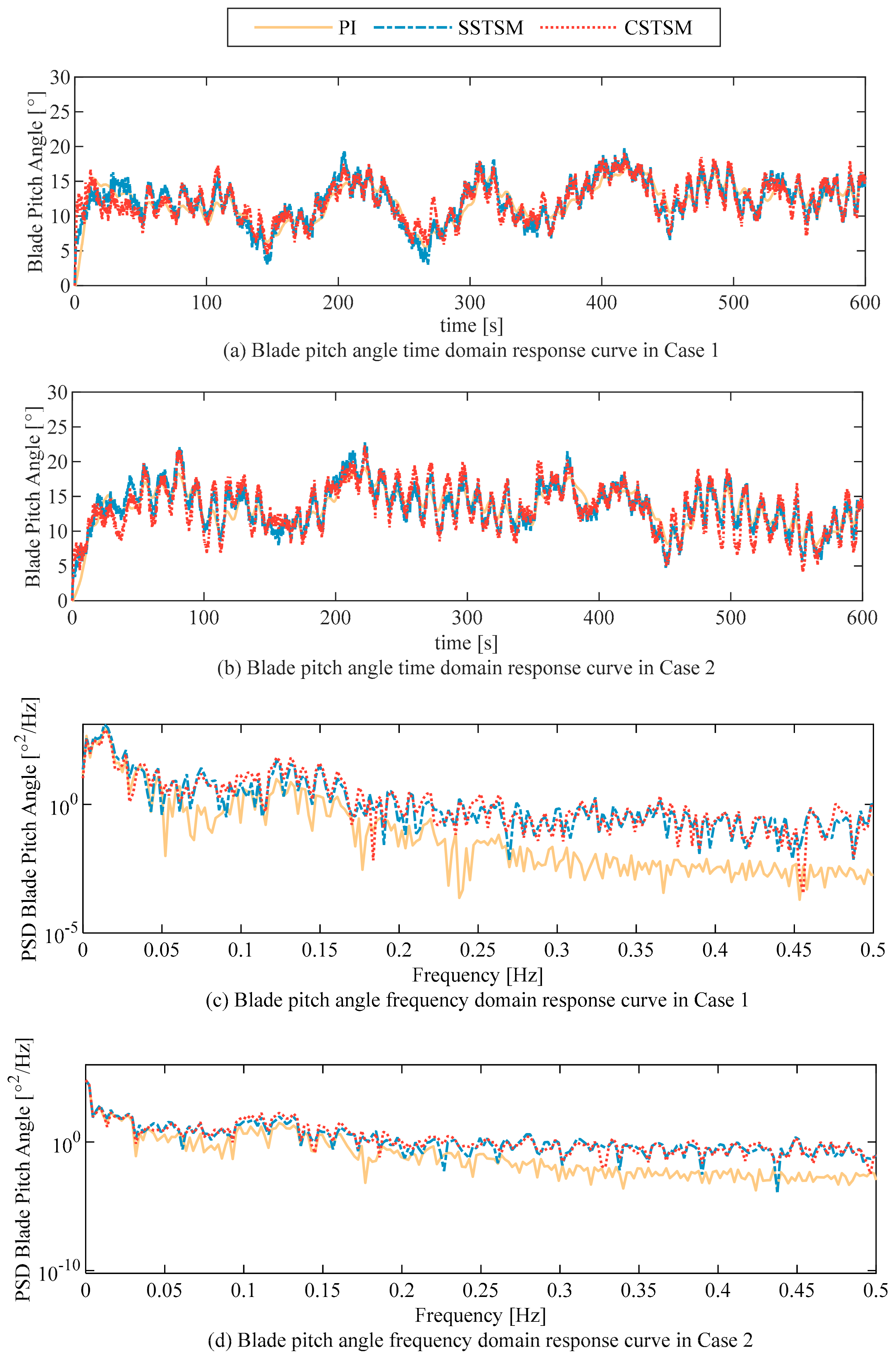
4.1. Time Domain Analysis of Power and Platform Motion
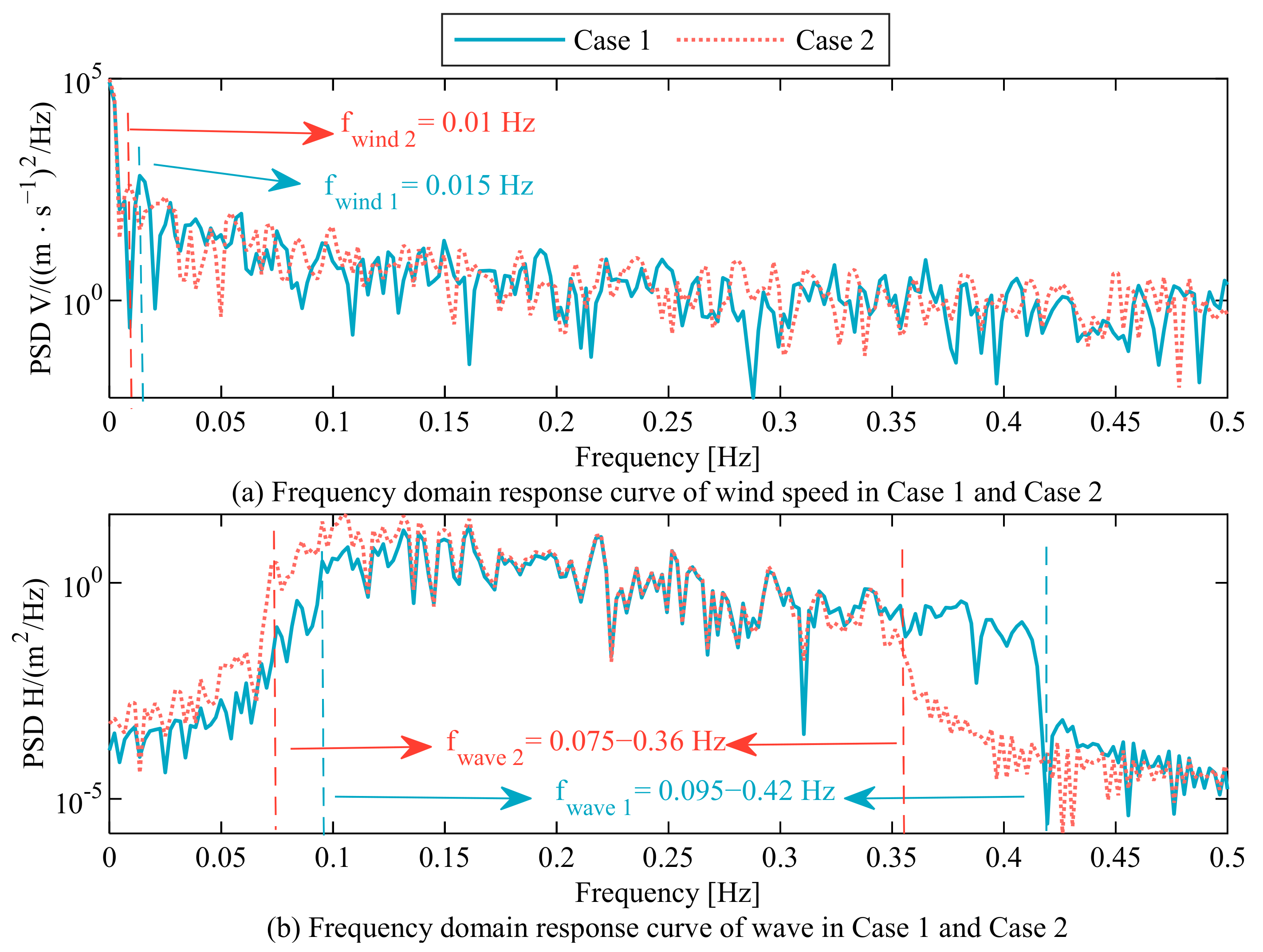
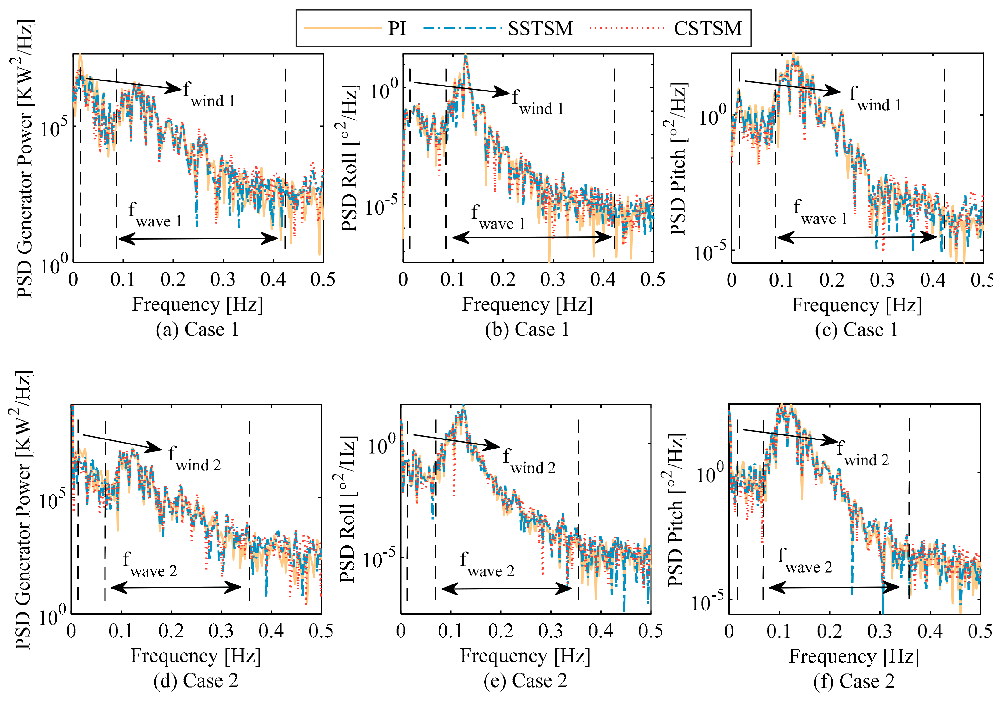
4.2. Formatting of Mathematical Components
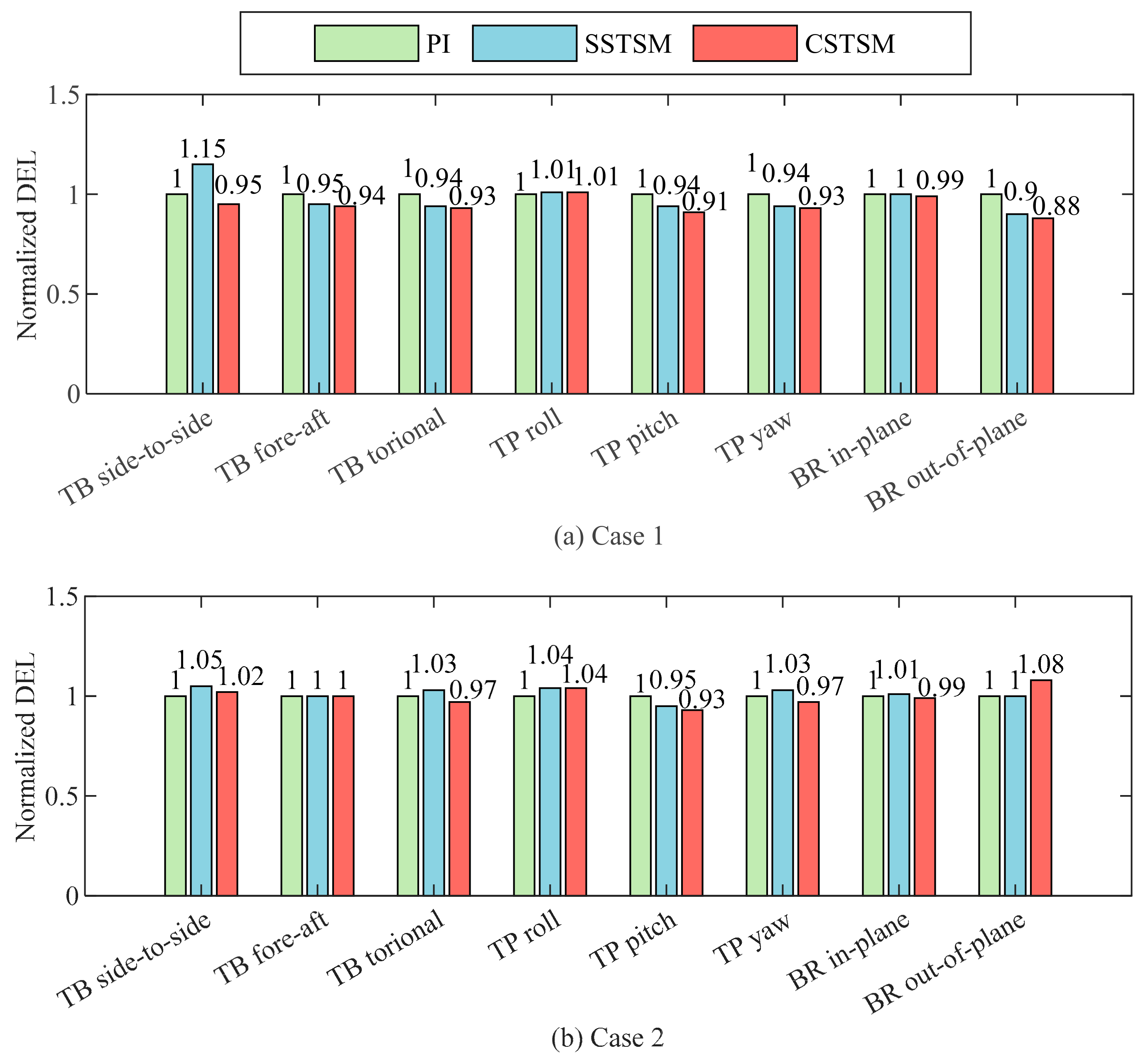
4.3. Tower and Blade Load Analysis
4.4. Observer Performance
5. Conclusions
Author Contributions
Funding
Institutional Review Board Statement
Informed Consent Statement
Data Availability Statement
Conflicts of Interest
References
- Jung, C.; Schindler, D. Efficiency and effectiveness of global onshore wind energy utilization. Energy Convers. Manag. 2023, 280, 116788. [Google Scholar] [CrossRef]
- Tian, H.; Soltani, M.N.; Nielsen, M.E. Review of floating wind turbine damping technology. Ocean Eng. 2023, 278, 114365. [Google Scholar] [CrossRef]
- Micallef, D.; Rezaeiha, A. Floating offshore wind turbine aerodynamics: Trends and future challenges. Renew. Sustain. Energy Rev. 2021, 152, 111696. [Google Scholar] [CrossRef]
- Shah, S.A.A.; Gao, B.; Ahmad, I.; Ullah, H.; Ahmed, N.; Saeed, A. Adaptive Backstepping Integral Sliding Mode Control for 5DOF Barge-Type OFWT under Output Constraint. J. Mar. Sci. Eng. 2023, 11, 492. [Google Scholar] [CrossRef]
- Shah, K.A.; Meng, F.; Li, Y.; Nagamune, R.; Zhou, Y.; Ren, Z.; Jiang, Z. A synthesis of feasible control methods for floating offshore wind turbine system dynamics. Renew. Sustain. Energy Rev. 2021, 151, 111525. [Google Scholar] [CrossRef]
- Ha, K.; Truong, H.V.A.; Dang, T.D.; Ahn, K.K. Recent control technologies for floating offshore wind energy system: A review. Int. J. Precis. Eng. Manuf.-Green Technol. 2021, 8, 281–301. [Google Scholar] [CrossRef]
- Zhang, M.; Li, X.; Tong, J.; Xu, J. Load control of floating wind turbine on a Tension-Leg-Platform subject to extreme wind condition. Renew. Energy 2020, 151, 993–1007. [Google Scholar] [CrossRef]
- Park, G.; Oh, K.-Y.; Nam, W. Bilinear tuned mass damper for spar-type floating wind turbines. Ocean. Eng. 2022, 261, 112081. [Google Scholar] [CrossRef]
- Clement, C.; Kosleck, S.; Lie, T. Investigation of viscous damping effect on the coupled dynamic response of a hybrid floating platform concept for offshore wind turbines. Ocean. Eng. 2021, 225, 108836. [Google Scholar] [CrossRef]
- Lackner, M.A.; Rotea, M.A. Passive structural control of offshore wind turbines. Wind. Energy 2011, 14, 373–388. [Google Scholar] [CrossRef]
- Stewart, G.; Lackner, M. Offshore wind turbine load reduction employing optimal passive tuned mass damping systems. IEEE Trans. Control. Syst. Technol. 2013, 21, 1090–1104. [Google Scholar] [CrossRef]
- Sarkar, S.; Fitzgerald, B. Vibration control of spar-type floating offshore wind turbine towers using a tuned mass-damper-inerter. Struct. Control Health Monit. 2020, 27, e2471. [Google Scholar] [CrossRef]
- Javier, L.; Eider, R.; Josu, J.; Santiago, A. Review of Control Technologies for Floating Offshore Wind turbines. Renew. Sustain. Energy Rev. 2022, 167, 112787. [Google Scholar]
- Larsen, T.J.; Hanson, T.D. A method to avoid negative damped low frequent tower vibrations for a floating, pitch controlled wind turbine. In Proceedings of the Journal of Physics: Conference Series; IOP Publishing: Bristol, UK, 2007; p. 12073. [Google Scholar]
- Zhang, Y.; Yang, X.; Liu, S. Data-driven predictive control for floating offshore wind turbines based on deep learning and multi-objective optimization. Ocean. Eng. 2022, 266, 112820. [Google Scholar] [CrossRef]
- Wakui, T.; Yoshimura, M.; Yokoyama, R. Multiple-feedback control of power output and platform pitching motion for a floating offshore wind turbine-generator system. Energy 2017, 141, 563–578. [Google Scholar] [CrossRef]
- Radaideh, A.; Bodoor, M.M.; Al-Quraan, A. Active and reactive power control for wind turbines based DFIG using LQR controller with optimal gain-scheduling. J. Electr. Comput. Eng. 2021, 2021, 1–19. [Google Scholar] [CrossRef]
- Sarkar, S.; Chen, L.; Fitzgerald, B.; Basu, B. Multi-resolution wavelet pitch controller for spar-type floating offshore wind turbines including wave-current interactions. J. Sound Vib. 2020, 470, 115170. [Google Scholar] [CrossRef]
- Yang, B.; Yu, T.; Shu, H.; Dong, J.; Jiang, L. Robust sliding-mode control of wind energy conversion systems for optimal power extraction via nonlinear perturbation observers. Appl. Energy 2018, 210, 711–723. [Google Scholar] [CrossRef]
- Kelkoul, B.; Boumediene, A. Stability analysis and study between classical sliding mode control (SMC) and super twisting algorithm (STA) for doubly fed induction generator (DFIG) under wind turbine. Energy 2021, 214, 118871. [Google Scholar] [CrossRef]
- Shah, S.A.A.; Gao, B.; Ahmed, N.; Liu, C. Advanced robust control techniques for the stabilization of translational oscillator with rotational actuator based barge-type OFWT. Proc. Inst. Mech. Eng. Part M J. Eng. Marit. Environ. 2021, 235, 327–343. [Google Scholar] [CrossRef]
- Han, Y.; Liu, X. Continuous higher-order sliding mode control with time-varying gain for a class of uncertain nonlinear systems. ISA Trans. 2016, 62, 193–201. [Google Scholar] [CrossRef]
- Liu, X.; Wang, C.; Han, Y. Second-order sliding mode control of DFIG based variable speed wind turbine for maximum power point tracking. Acta Autom. Sin. 2017, 43, 1434–1442. [Google Scholar]
- Zhang, C.; Gutierrez, S.; Plestan, F.; de León-Morales, J. Adaptive super-twisting control of floating wind turbines with collective blade pitch control. IFAC-Pap. 2019, 52, 117–122. [Google Scholar] [CrossRef]
- Zhang, C.; Plestan, F. Individual/collective blade pitch control of floating wind turbine based on adaptive second order sliding mode. Ocean. Eng. 2021, 228, 108897. [Google Scholar] [CrossRef]
- Gutierrez, S.V.; Zhang, C.; de Leon-Morales, J.; Plestan, F. A simplified version of adaptive super twisting—Application to the control of floating wind turbine. Control Eng. Pract. 2022, 125, 105208. [Google Scholar] [CrossRef]
- Li, S.; Han, Y.; Pan, W.; Liu, S.; Hou, M. Variable-gain higher-order sliding mode pitch control of floating offshore wind turbine. J. Mar. Sci. Eng 2021, 9, 1172. [Google Scholar] [CrossRef]
- Ali, S.A.; Langlois, N. Sliding mode control for diesel engine air path subject to matched and unmatched disturbances using extended state observer. Math. Probl. Eng. 2013, 2013, 712723. [Google Scholar] [CrossRef]
- Guermouche, M.; Ali, S.A.; Langlois, N. Super-twisting algorithm for DC motor position control via disturbance observer. IFAC-Pap. 2015, 48, 43–48. [Google Scholar] [CrossRef]
- Mohamed, G.; Sofiane, A.A.; Nicolas, L. Adaptive super twisting extended state observer based sliding mode control for diesel engine air path subject to matched and unmatched disturbance. Math. Comput. Simul. 2018, 151, 111–130. [Google Scholar] [CrossRef]
- Zhao, L.; Zheng, C.; Wang, Y.; Liu, B. A finite-time control for a pneumatic cylinder servo system based on a super-twisting extended state observer. IEEE Trans. Syst. Man Cybern. Syst. 2019, 51, 1164–1173. [Google Scholar] [CrossRef]
- Yang, Y.; Yan, Y.; Xu, X.; Gong, B. Super-twisting algorithm with fast super-twisting disturbance observer for steer-by-wire vehicles. Proc. Inst. Mech. Eng. Part D J. Automob. Eng. 2021, 235, 2324–2340. [Google Scholar] [CrossRef]
- Liu, Q.-S.; Miao, W.-P.; Yue, M.-N.; Li, C.; Wang, B.; Ding, Q. Dynamic response of offshore wind turbine on 3× 3 barge array floating platform under extreme sea conditions. China Ocean. Eng. 2021, 35, 186–200. [Google Scholar] [CrossRef]
- Jonkman, J.M.; Buhl, M.L. FAST User’s Guide; National Renewable Energy Laboratory: Golden, CO, USA, 2005; Volume 365. [Google Scholar]
- Colombo, L.; Corradini, M.L.; Ippoliti, G.; Orlando, G. Pitch angle control of a wind turbine operating above the rated wind speed: A sliding mode control approach. ISA Trans. 2020, 96, 95–102. [Google Scholar] [CrossRef] [PubMed]
- Lackner, M.A. An investigation of variable power collective pitch control for load mitigation of floating offshore wind turbines. Wind. Energy 2013, 16, 435–444. [Google Scholar] [CrossRef]
- Seeber, R.; Horn, M. Stability proof for a well-established super-twisting parameter setting. Automatica 2017, 84, 241–243. [Google Scholar] [CrossRef]
- Moreno, J.A.; Osorio, M. A Lyapunov approach to second-order sliding mode controllers and observers. In Proceedings of the 2008 47th IEEE Conference on Decision and Control, Cancun, Mexico, 9–11 December 2008; pp. 2856–2861. [Google Scholar]
- Obeid, H.; Fridman, L.; Laghrouche, S.; Harmouche, M.; Golkani, M.A. Adaptation of Levant’s differentiator based on barrier function. Int. J. Control 2018, 91, 2019–2027. [Google Scholar] [CrossRef]
- Obeid, H.; Laghrouche, S.; Fridman, L.; Chitour, Y.; Harmouche, M. Barrier function-based adaptive super-twisting controller. IEEE Trans. Autom. Control 2020, 65, 4928–4933. [Google Scholar] [CrossRef]
- Jonkman, J.; Butterfield, S.; Musial, W.; Scott, G. Definition of a 5-MW Reference Wind Turbine for Offshore System Development; National Renewable Energy Laboratory: Golden, CO, USA, 2009. [Google Scholar]
- Hayman, G. MLife Theory Manual for Version 1.00; National Renewable Energy Laboratory: Golden, CO, USA, 2012; Volume 74, p. 106. [Google Scholar]


| SOSM | second-order sliding mode |
| PI | proportional integral |
| FOWT | floating offshore wind turbine |
| TMD | tuned mass dampers |
| TMDI | tuned mass-damper-inerter |
| SMC | sliding mode control |
| PSD | power spectral density |
| STC | super-twisting control |
| CSTSM | composite super-twisting sliding mode |
| SSTSM | standard super-twisting sliding mode |
| DEL | damage equivalent load |
| RMS | root mean square |
| Parameter | Value |
|---|---|
| Number of Blades | 3 |
| Rated Power | 5 MW |
| Rotor Diameter | 126 m |
| Hub Height | 90 m |
| Rated Rotor Speed | 12.1 rpm |
| Rated Wind Speed | 11.4 m/s |
| Rotor Mass | 110,000 kg |
| Nacelle Mass | 240,000 kg |
| Tower Mass | 347,460 kg |
| Generator inertia | 534.116 kg·m2 |
| Nacelle inertia | 2607.89 × 103 kg·m2 |
| Hub inertia | 115.926 × 10³ kg·m2 |
| Case | Wind Speed (m/s) | Turbulence Intensity (%) | Significant Wave Height (m) | Peak Spectral Period (s) |
|---|---|---|---|---|
| Case 1 | 18 | 16.98 | 3.5 | 10.5 |
| Case 2 | 20 | 16.48 | 5 | 12.5 |
Disclaimer/Publisher’s Note: The statements, opinions and data contained in all publications are solely those of the individual author(s) and contributor(s) and not of MDPI and/or the editor(s). MDPI and/or the editor(s) disclaim responsibility for any injury to people or property resulting from any ideas, methods, instructions or products referred to in the content. |
© 2023 by the authors. Licensee MDPI, Basel, Switzerland. This article is an open access article distributed under the terms and conditions of the Creative Commons Attribution (CC BY) license (https://creativecommons.org/licenses/by/4.0/).
Share and Cite
Yang, W.; Han, Y.; Ma, R.; Hou, M.; Yang, G. A Composite Super-Twisting Sliding Mode Approach for Platform Motion Suppression and Power Regulation of Floating Offshore Wind Turbine. J. Mar. Sci. Eng. 2023, 11, 2318. https://doi.org/10.3390/jmse11122318
Yang W, Han Y, Ma R, Hou M, Yang G. A Composite Super-Twisting Sliding Mode Approach for Platform Motion Suppression and Power Regulation of Floating Offshore Wind Turbine. Journal of Marine Science and Engineering. 2023; 11(12):2318. https://doi.org/10.3390/jmse11122318
Chicago/Turabian StyleYang, Wenxiang, Yaozhen Han, Ronglin Ma, Mingdong Hou, and Guang Yang. 2023. "A Composite Super-Twisting Sliding Mode Approach for Platform Motion Suppression and Power Regulation of Floating Offshore Wind Turbine" Journal of Marine Science and Engineering 11, no. 12: 2318. https://doi.org/10.3390/jmse11122318
APA StyleYang, W., Han, Y., Ma, R., Hou, M., & Yang, G. (2023). A Composite Super-Twisting Sliding Mode Approach for Platform Motion Suppression and Power Regulation of Floating Offshore Wind Turbine. Journal of Marine Science and Engineering, 11(12), 2318. https://doi.org/10.3390/jmse11122318