Figure 1.
Side view of small catamaran rescue craft structure.
Figure 1.
Side view of small catamaran rescue craft structure.
Figure 2.
3-DOF hydraulic interconnected suspension system for rescue boats.
Figure 2.
3-DOF hydraulic interconnected suspension system for rescue boats.
Figure 3.
Hydraulic interconnected suspension system model.
Figure 3.
Hydraulic interconnected suspension system model.
Figure 4.
Acceleration RMS value as a function of the chamber length.
Figure 4.
Acceleration RMS value as a function of the chamber length.
Figure 5.
Roll angle RMS value as a function of the chamber length.
Figure 5.
Roll angle RMS value as a function of the chamber length.
Figure 6.
Pitch angle RMS value as a function of the chamber length.
Figure 6.
Pitch angle RMS value as a function of the chamber length.
Figure 7.
Acceleration RMS value as a function of the hydraulic cylinder inner diameter.
Figure 7.
Acceleration RMS value as a function of the hydraulic cylinder inner diameter.
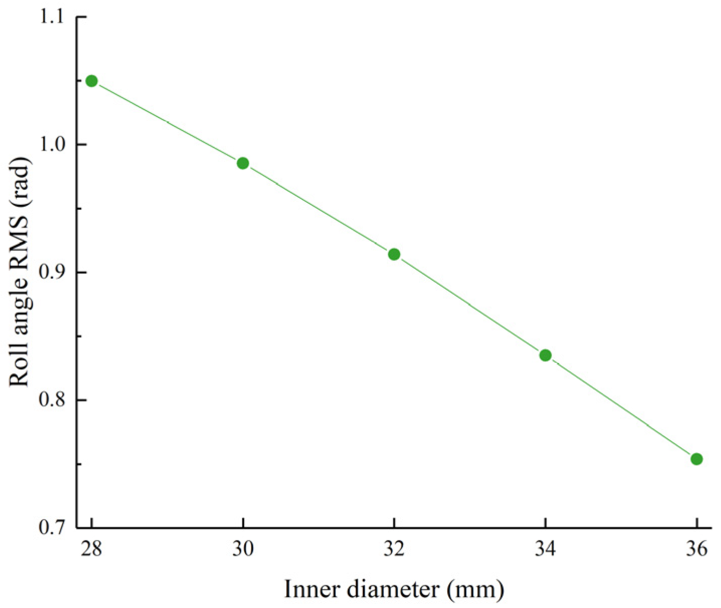
Figure 8.
Roll angle RMS value as a function of the hydraulic cylinder inner diameter.
Figure 8.
Roll angle RMS value as a function of the hydraulic cylinder inner diameter.
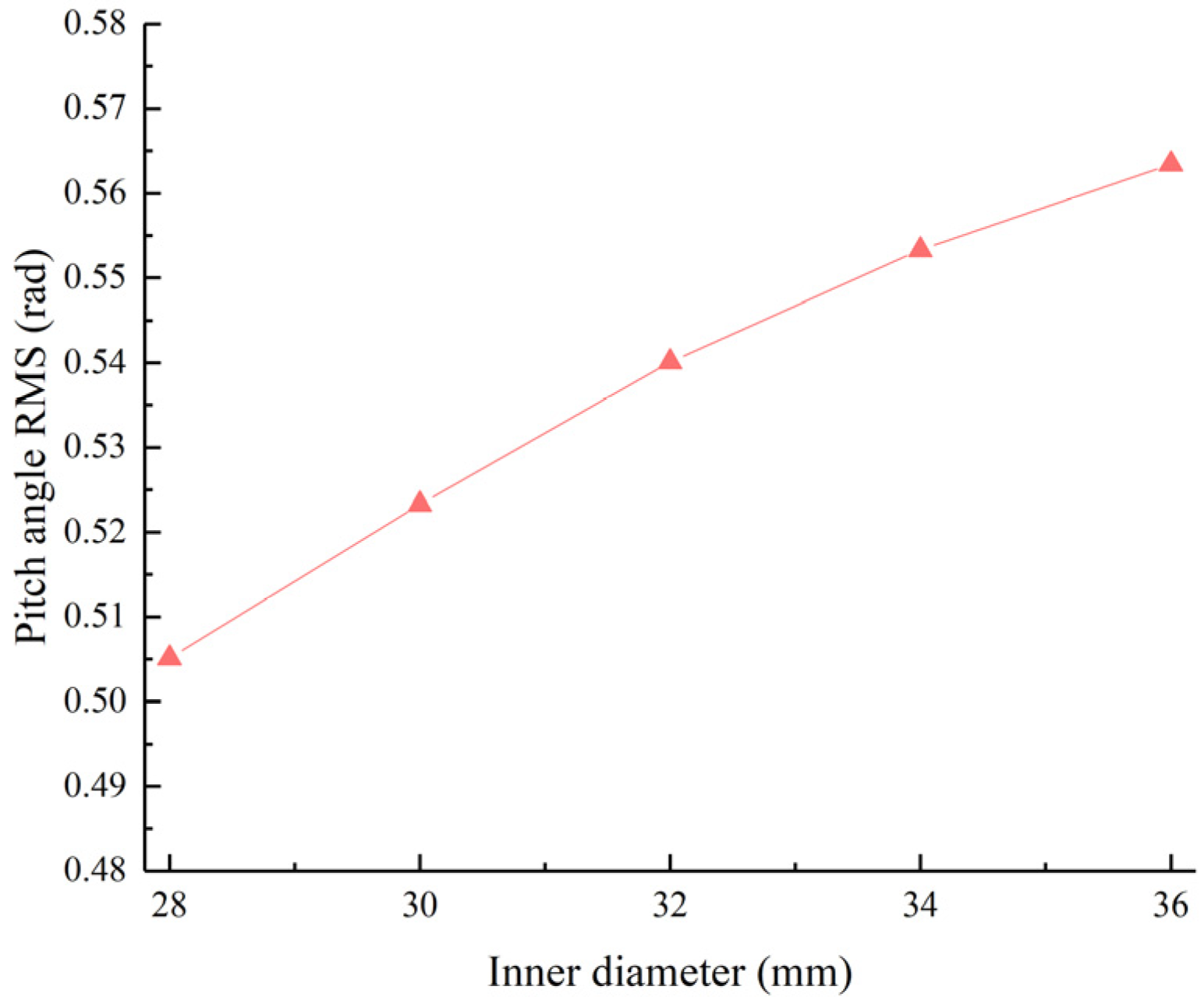
Figure 9.
Pitch angle RMS value as a function of the hydraulic cylinder inner diameter.
Figure 9.
Pitch angle RMS value as a function of the hydraulic cylinder inner diameter.
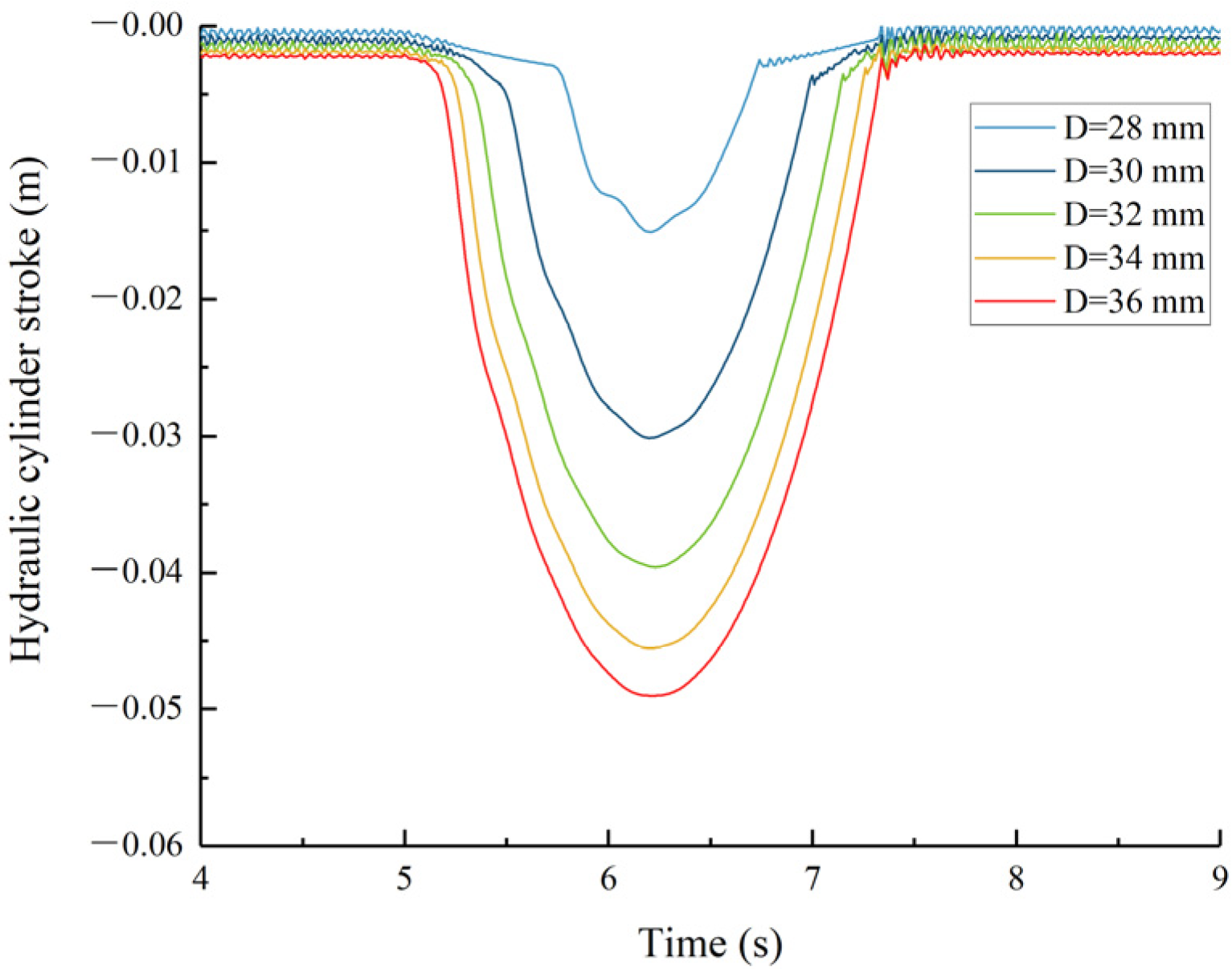
Figure 10.
Intermediate hydraulic cylinder stroke.
Figure 10.
Intermediate hydraulic cylinder stroke.
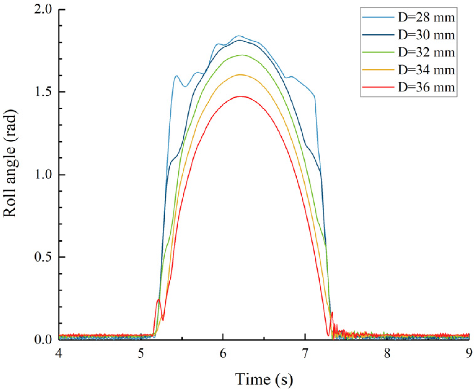
Figure 11.
Roll angle of the main hull.
Figure 11.
Roll angle of the main hull.
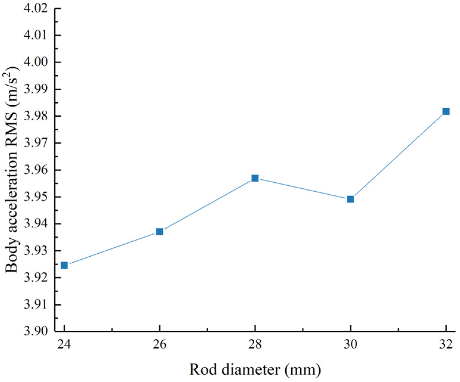
Figure 12.
Acceleration RMS value as a function of the piston rod diameter.
Figure 12.
Acceleration RMS value as a function of the piston rod diameter.
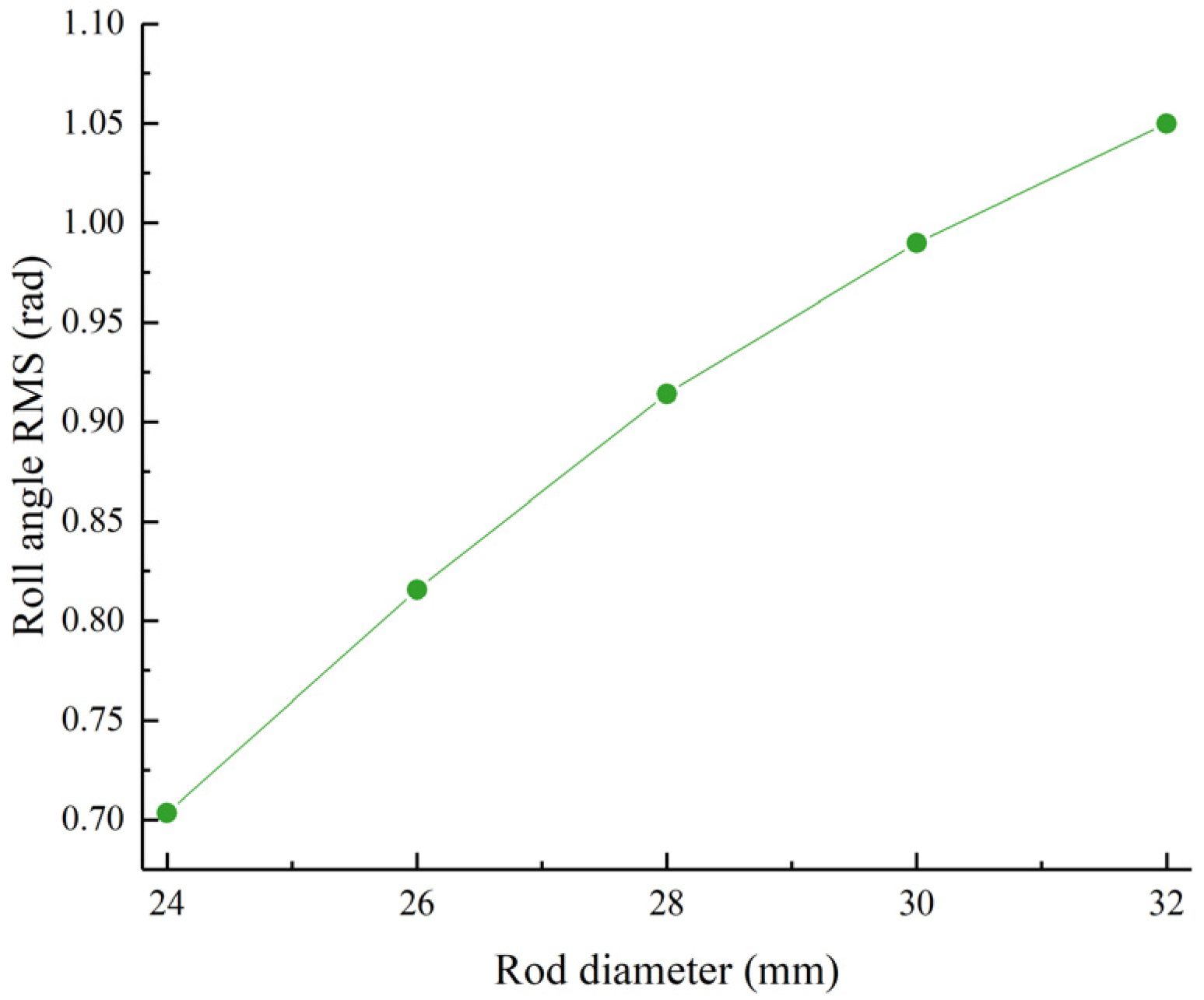
Figure 13.
Roll angle RMS value as a function of the piston rod diameter.
Figure 13.
Roll angle RMS value as a function of the piston rod diameter.
Figure 14.
Pitch angle RMS value as a function of the piston rod diameter.
Figure 14.
Pitch angle RMS value as a function of the piston rod diameter.
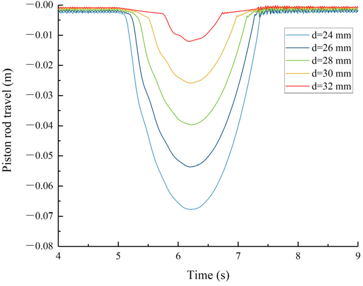
Figure 15.
Intermediate hydraulic cylinder stroke.
Figure 15.
Intermediate hydraulic cylinder stroke.
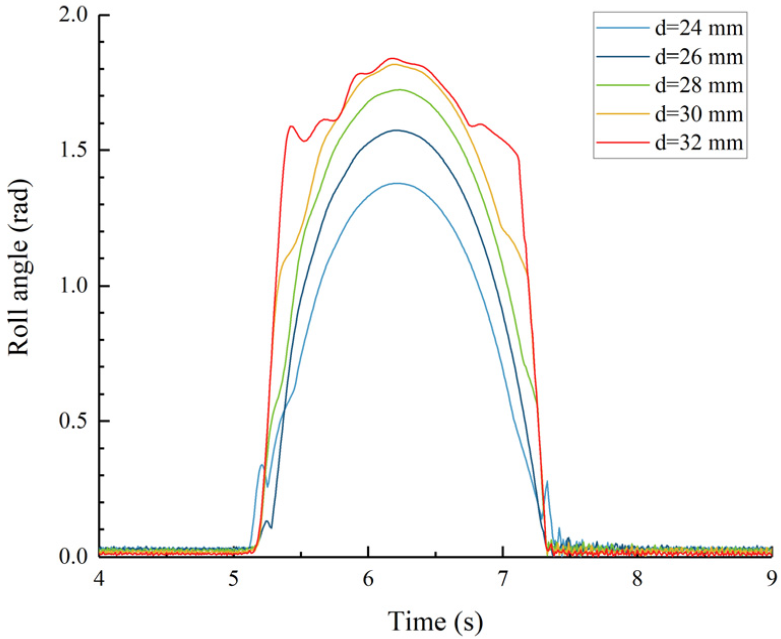
Figure 16.
Roll angle of the main hull.
Figure 16.
Roll angle of the main hull.
Figure 17.
Acceleration RMS value as a function of the inner diameter and the piston rod diameter.
Figure 17.
Acceleration RMS value as a function of the inner diameter and the piston rod diameter.
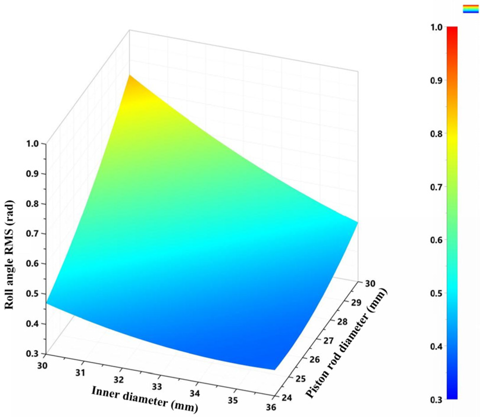
Figure 18.
Roll angle RMS value as a function of the inner diameter and the piston rod diameter.
Figure 18.
Roll angle RMS value as a function of the inner diameter and the piston rod diameter.
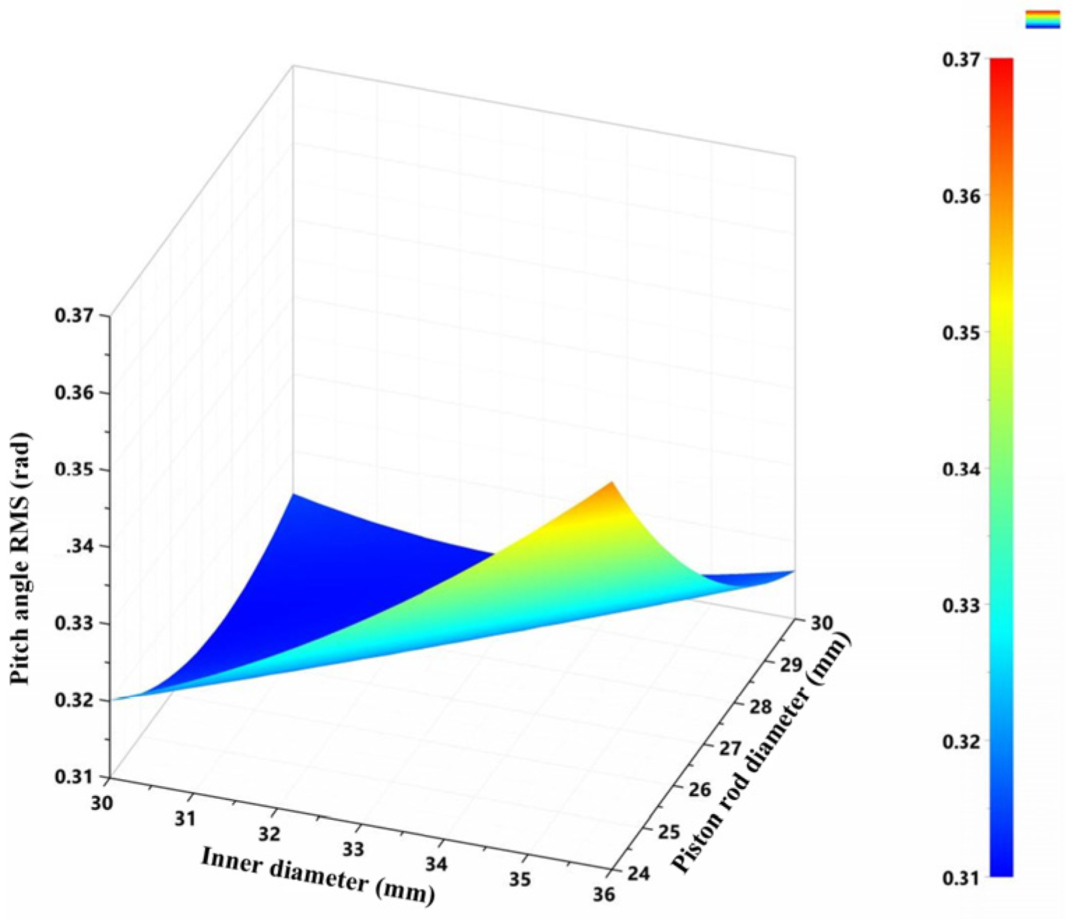
Figure 19.
Pitch angle RMS value as a function of the inner diameter and the piston rod diameter.
Figure 19.
Pitch angle RMS value as a function of the inner diameter and the piston rod diameter.
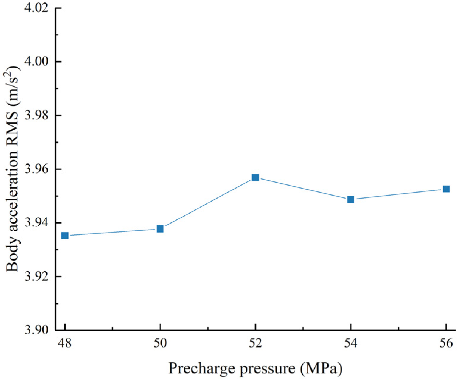
Figure 20.
Acceleration RMS value as a function of the left accumulator pre-charge pressure.
Figure 20.
Acceleration RMS value as a function of the left accumulator pre-charge pressure.
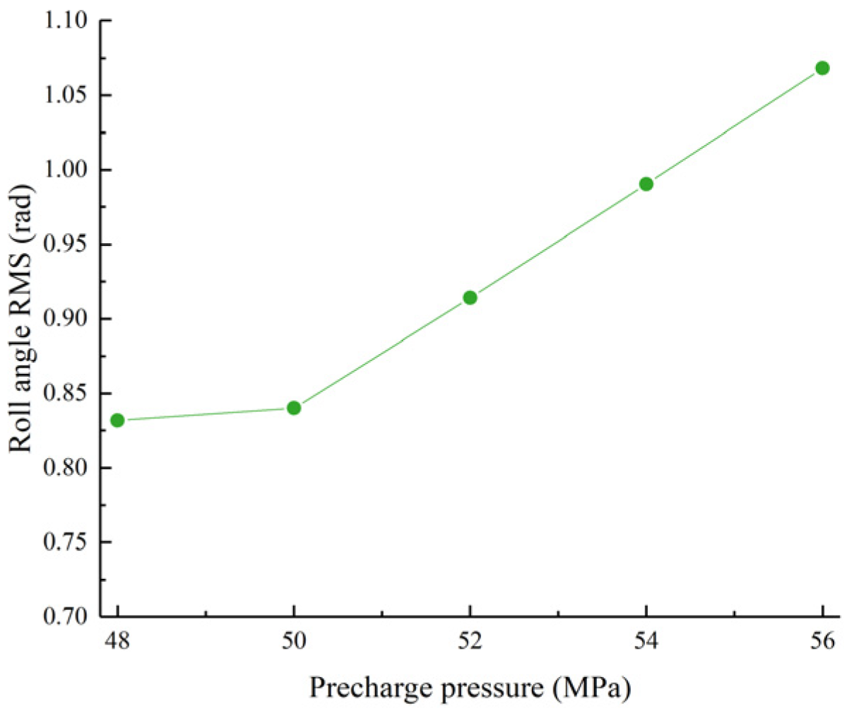
Figure 21.
Roll angle RMS value as a function of the left accumulator pre-charge pressure.
Figure 21.
Roll angle RMS value as a function of the left accumulator pre-charge pressure.
Figure 22.
Pitch angle RMS value as a function of the left accumulator pre-charge pressure.
Figure 22.
Pitch angle RMS value as a function of the left accumulator pre-charge pressure.
Figure 23.
Acceleration RMS value as a function of the right accumulator pre-charge pressure.
Figure 23.
Acceleration RMS value as a function of the right accumulator pre-charge pressure.
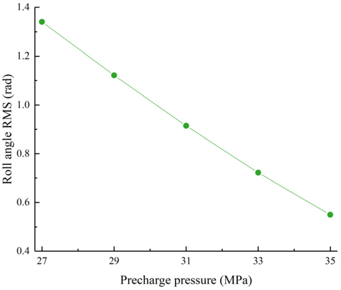
Figure 24.
Roll angle RMS value as a function of the right accumulator pre-charge pressure.
Figure 24.
Roll angle RMS value as a function of the right accumulator pre-charge pressure.
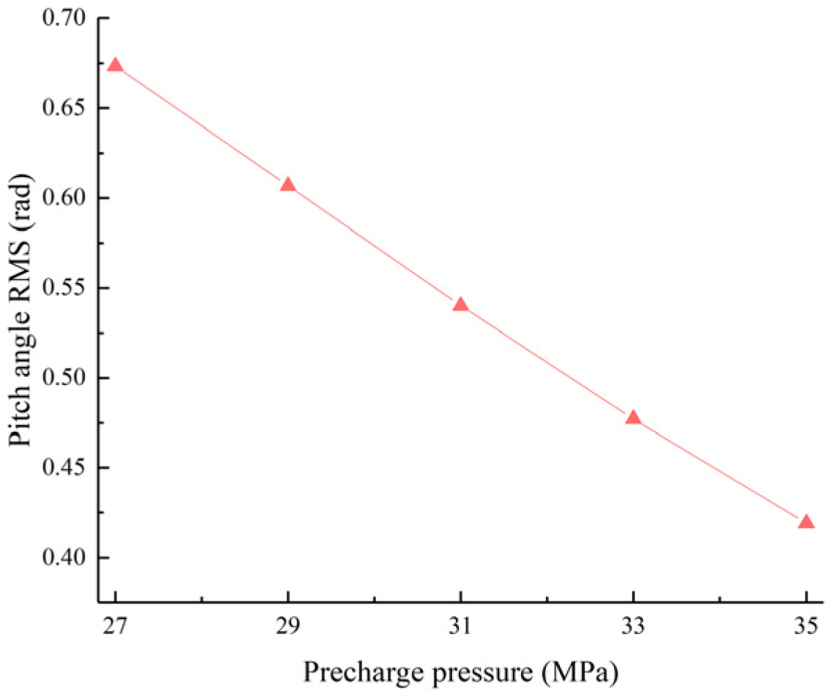
Figure 25.
Pitch angle RMS value as a function of the right accumulator pre-charge pressure.
Figure 25.
Pitch angle RMS value as a function of the right accumulator pre-charge pressure.
Figure 26.
Acceleration RMS value as a function of the left and right accumulator pre-charge pressures.
Figure 26.
Acceleration RMS value as a function of the left and right accumulator pre-charge pressures.
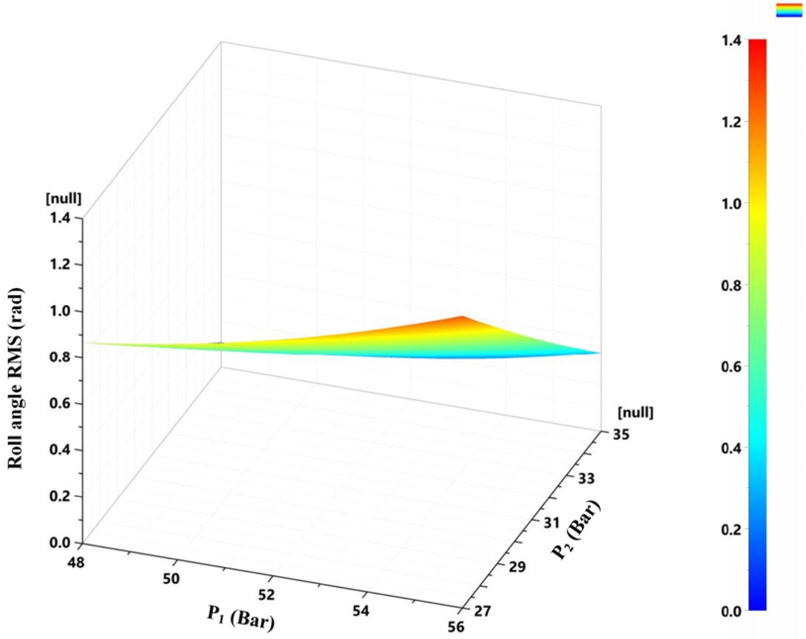
Figure 27.
Roll angle RMS value as a function of the left and right accumulator pre-charge pressures.
Figure 27.
Roll angle RMS value as a function of the left and right accumulator pre-charge pressures.
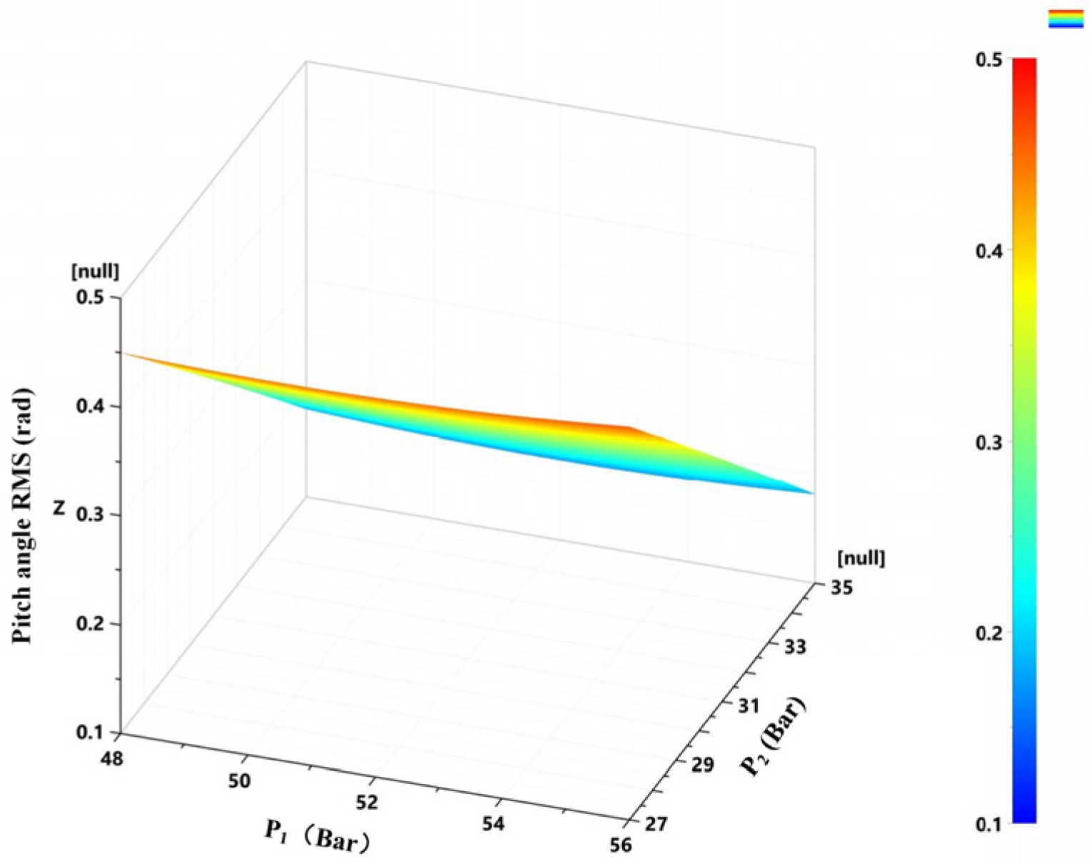
Figure 28.
Pitch angle RMS value as a function of the left and right accumulator pre-charge pressures.
Figure 28.
Pitch angle RMS value as a function of the left and right accumulator pre-charge pressures.
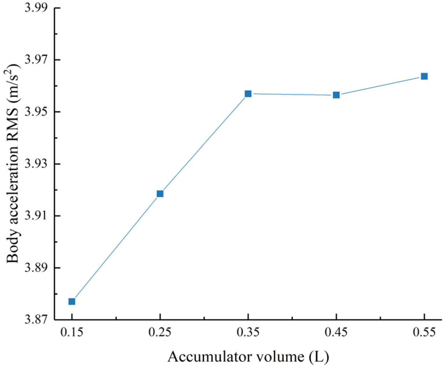
Figure 29.
Acceleration RMS value as a function of the accumulator volume.
Figure 29.
Acceleration RMS value as a function of the accumulator volume.
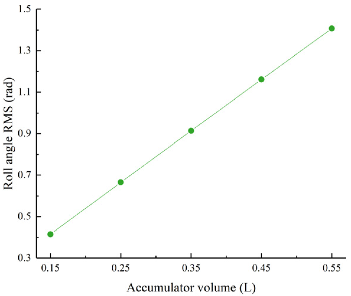
Figure 30.
Roll angle RMS value as a function of the accumulator volume.
Figure 30.
Roll angle RMS value as a function of the accumulator volume.
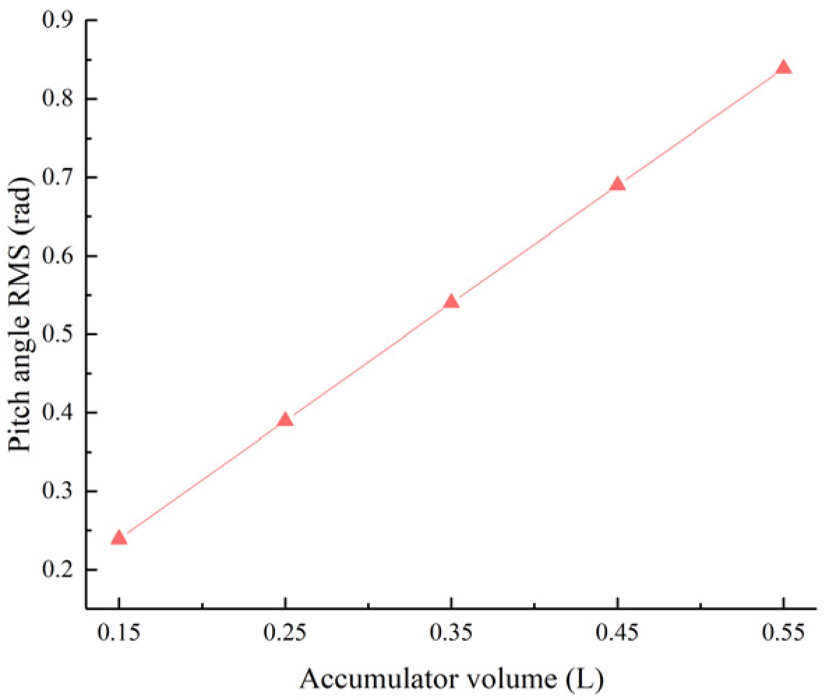
Figure 31.
Pitch angle RMS value as a function of the accumulator volume.
Figure 31.
Pitch angle RMS value as a function of the accumulator volume.
Figure 32.
Hydraulic cylinder flow difference.
Figure 32.
Hydraulic cylinder flow difference.
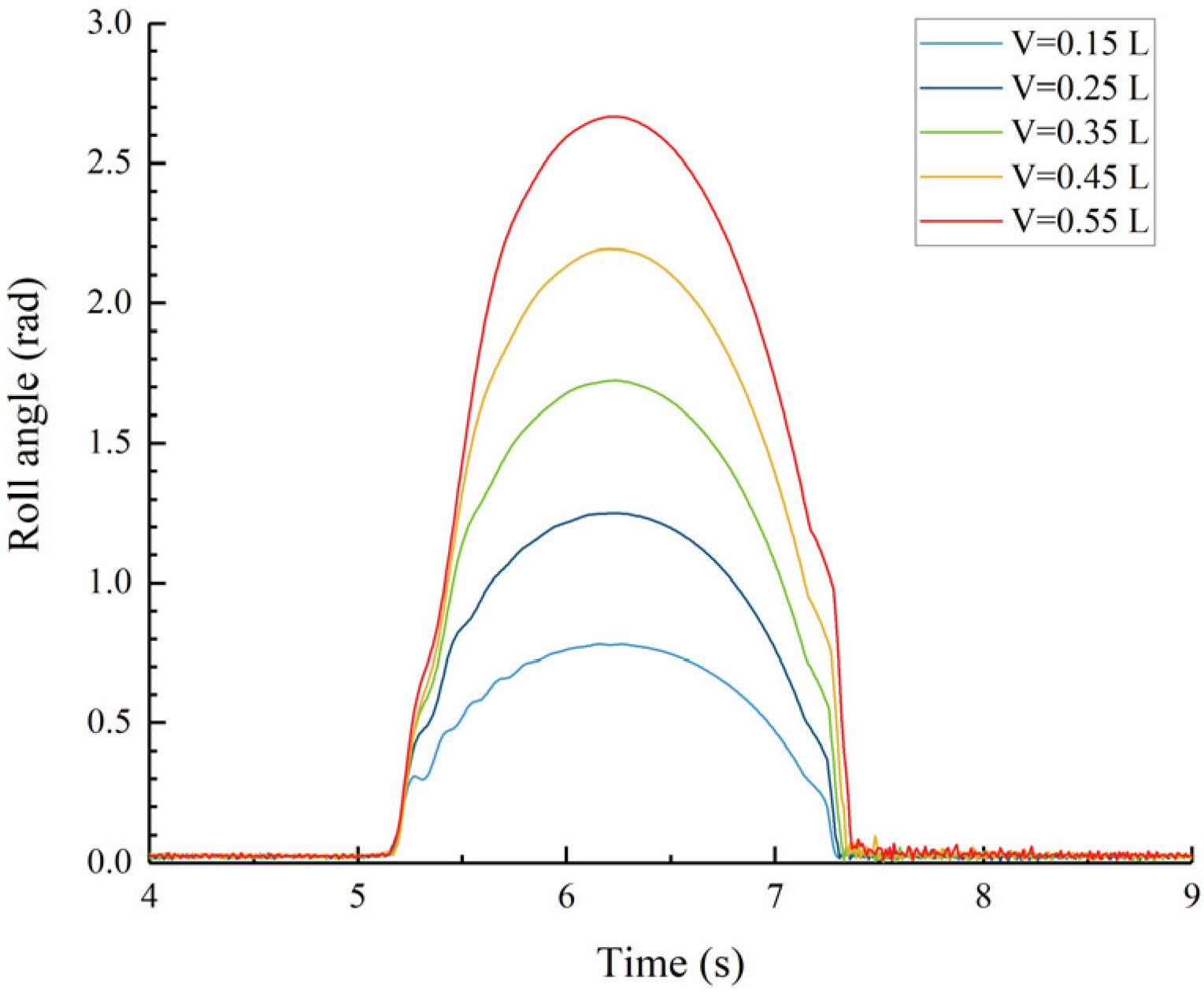
Figure 33.
Roll angle of the main hull.
Figure 33.
Roll angle of the main hull.
Figure 34.
Acceleration RMS value as a function of the damping valve aperture size.
Figure 34.
Acceleration RMS value as a function of the damping valve aperture size.
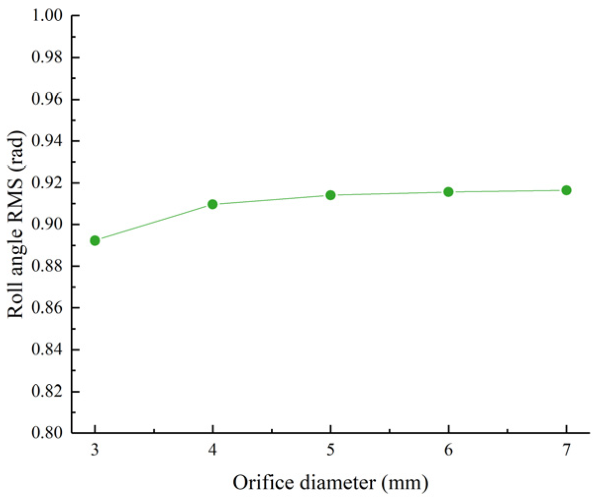
Figure 35.
Roll angle RMS value as a function of the damping valve aperture size.
Figure 35.
Roll angle RMS value as a function of the damping valve aperture size.
Figure 36.
Pitch angle RMS value as a function of the damping valve aperture size.
Figure 36.
Pitch angle RMS value as a function of the damping valve aperture size.
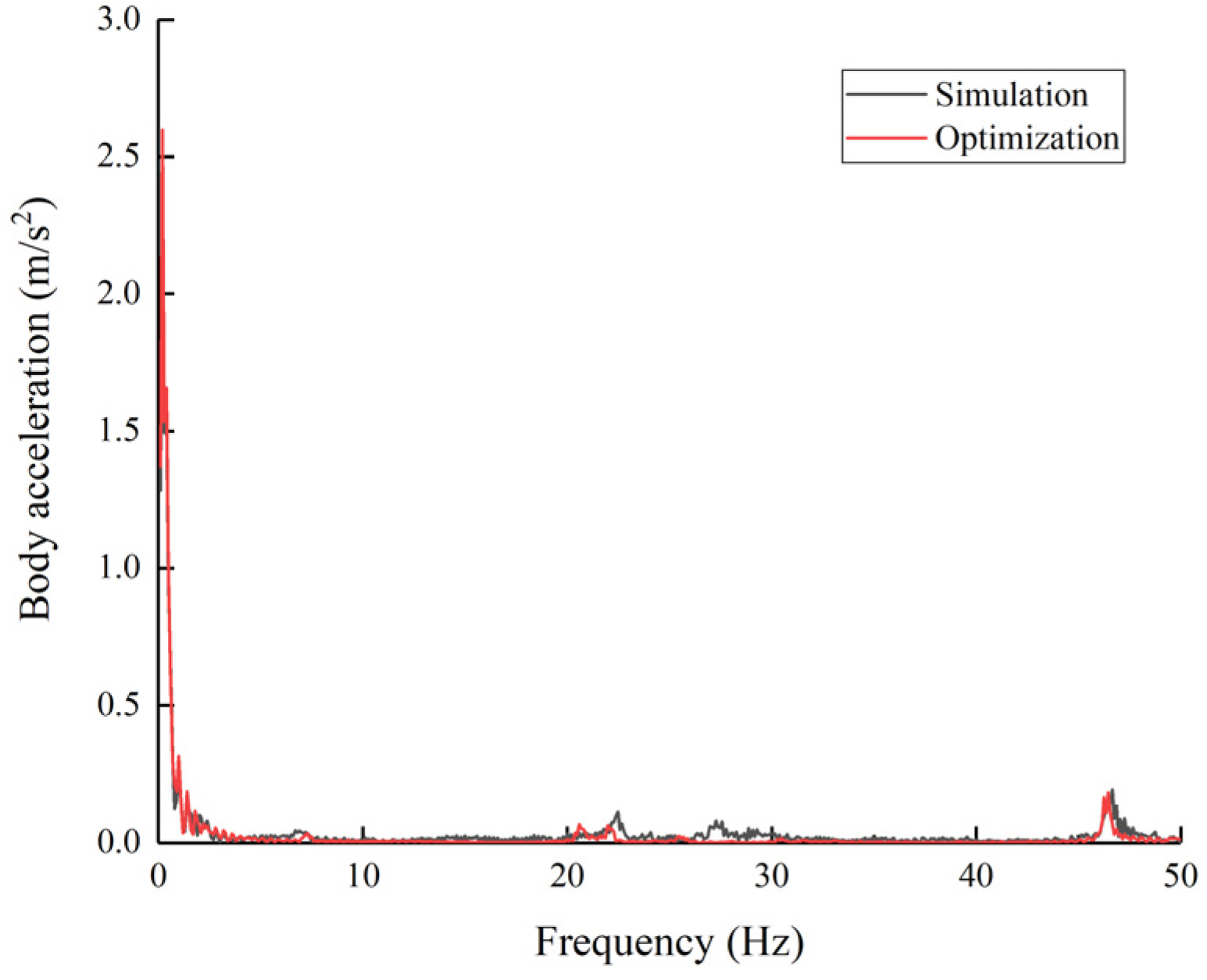
Figure 37.
Vertical acceleration of the main hull.
Figure 37.
Vertical acceleration of the main hull.
Figure 38.
Main hull roll angle with time.
Figure 38.
Main hull roll angle with time.
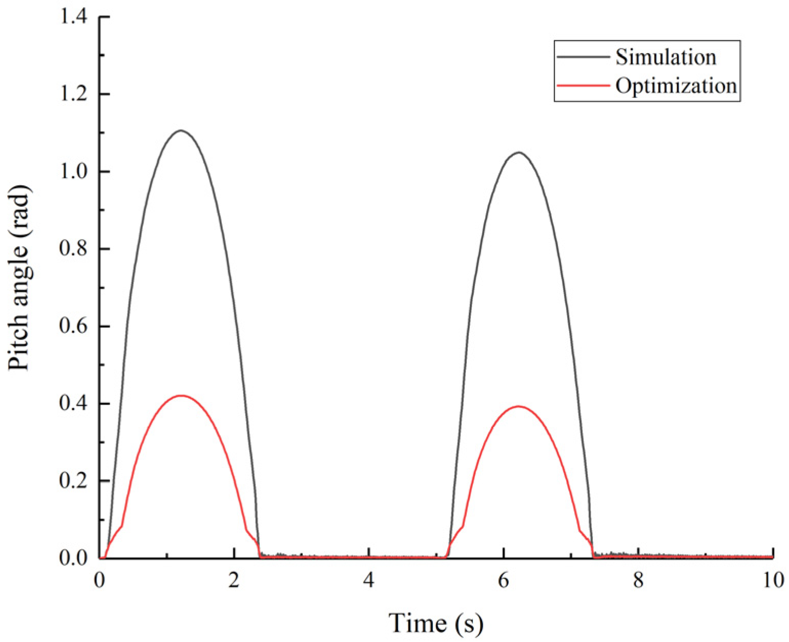
Figure 39.
Main hull pitch angle with time.
Figure 39.
Main hull pitch angle with time.
Table 1.
Main parameters of the hydraulic interconnected suspension system.
Table 1.
Main parameters of the hydraulic interconnected suspension system.
| Parameter | Value | Unit |
|---|
| Two-stage hydraulic cylinder inner diameter/D | 50 | mm |
| Two-way hydraulic cylinder piston rod diameter/d | 36 | mm |
| Two-way hydraulic cylinder stroke/L | −150–150 | mm |
| Symmetric hydraulic cylinder diameter/D0 | 32 | mm |
| Symmetric hydraulic cylinder piston rod diameter/d0 | 28 | mm |
| Symmetric hydraulic cylinder stroke/L0 | −100–100 | mm |
| Accumulator volume/V0 | 0.35 | L |
| Left accumulator pre-charge pressure/P1 | 5.2 | MPa |
| Right accumulator pre-charge pressure/P2 | 3.1 | MPa |
| Damping valve aperture size/r | 5 | mm |
| 25% of the main hull mass/m1 | 550 | kg |
| 50% of the main hull mass/m2 | 97.5 | kg |
Table 2.
Simulation parameters for the symmetric hydraulic cylinder chamber length analysis.
Table 2.
Simulation parameters for the symmetric hydraulic cylinder chamber length analysis.
| Length of Chamber/L (mm) | Parameter Change Gradient |
|---|
| 80 | −20% |
| 90 | −10% |
| 100 | Reference value |
| 110 | +10% |
| 120 | +20% |
Table 3.
Main hull heave displacement and peak velocity.
Table 3.
Main hull heave displacement and peak velocity.
| Symmetric Hydraulic Cylinder Inner Diameter/D0 (mm) | Peak Heave Displacement of the Main Hull (mm) | Peak Heave Velocity of the Main Hull (m/s) |
|---|
| 28 | 35.7276 | −0.0720 |
| 30 | 42.7771 | −0.0869 |
| 32 | 49.4203 | −0.0984 |
| 34 | 55.5105 | −0.1293 |
| 36 | 61.2230 | −0.1454 |
Table 4.
Main hull heave displacement and peak velocity.
Table 4.
Main hull heave displacement and peak velocity.
| Piston Rod Diameter/d0 (mm) | Peak Heave Displacement of the Main Hull (mm) | Peak Heave Velocity of the Main Hull (m/s) |
|---|
| 24 | 64.7805 | −0.1418 |
| 26 | 56.8600 | −0.1357 |
| 28 | 49.4324 | −0.0984 |
| 30 | 42.3381 | −0.0850 |
| 32 | 35.6796 | −0.0724 |
Table 5.
Maximum intermediate hydraulic cylinder strokes.
Table 5.
Maximum intermediate hydraulic cylinder strokes.
| Left Accumulator Pre-Charge Pressure/P1 (MPa) | Maximum Stroke of Symmetric Hydraulic Cylinder 4-1 (mm) | Maximum Stroke of Symmetric Hydraulic Cylinder 4-2 (mm) |
|---|
| 4.8 | 51.50 | 69.84 |
| 5.0 | 48.22 | 68.05 |
| 5.2 | 42.95 | 63.33 |
| 5.4 | 37.64 | 58.62 |
| 5.6 | 32.37 | 53.98 |
Table 6.
Maximum volume compression ratio of accumulator 2-2.
Table 6.
Maximum volume compression ratio of accumulator 2-2.
| Right Accumulator Pre-Charge Pressure/P2 (MPa) | Volume Compression Ratio of Accumulator 2-2 (%) |
|---|
| 2.7 | 42.55 |
| 2.9 | 39.66 |
| 3.1 | 36.81 |
| 3.3 | 34.02 |
| 3.5 | 31.27 |
Table 7.
Suspension system damping capacity characteristics.
Table 7.
Suspension system damping capacity characteristics.
| Nominal Accumulator Volume/V0 (L) | RMS Values of the Sub-Hull Vertical Acceleration (m/s2) | Suspension Vibration Absorption Capacity (m/s2) |
|---|
| 0.15 | 4.8284 | 0.9513 |
| 0.25 | 5.7682 | 1.8497 |
| 0.35 | 6.5002 | 2.5433 |
| 0.45 | 6.4463 | 2.4898 |
| 0.55 | 6.5730 | 2.6093 |
Table 8.
Suspension system optimization design variables.
Table 8.
Suspension system optimization design variables.
| Design Variable | Reference Value | Lower Limit | Upper Limit |
|---|
| Hydraulic cylinder inner diameter/D0 (mm) | 32 | 30 | 36 |
| Piston rod diameter/d0 (mm) | 28 | 24 | 30 |
| Left accumulator pre-charge pressure/P1 (MPa) | 5.2 | 4.8 | 5.6 |
| Right accumulator pre-charge pressure/P2 (MPa) | 3.1 | 2.7 | 3.5 |
| Accumulator volume/V0 (L) | 0.35 | 0.15 | 0.45 |
| Damping valve aperture size/r (mm) | 5 | 3 | 6 |
Table 9.
Optimization results.
Table 9.
Optimization results.
| Design Variable | Initial Value | Optimal Value | Rounded Value |
|---|
| Hydraulic cylinder inner diameter/D0 (mm) | 32 | 34.7 | 34 |
| Piston rod diameter/d0 (mm) | 28 | 28.2 | 28 |
| Left accumulator pre-charge pressure/P1 (MPa) | 5.2 | 5.082 | 5.08 |
| Right accumulator pre-charge pressure/P2 (MPa) | 3.1 | 3.497 | 3.50 |
| Accumulator volume/V0 (L) | 0.35 | 0.150 | 0.15 |
| Damping valve aperture size/r (mm) | 5 | 3.0 | 3 |
Table 10.
Optimization results.
Table 10.
Optimization results.
| Objective Function | Initial Value (m/s2) | Optimization Result (m/s2) | Optimization Rate (%) |
|---|
| RMS value of the vertical acceleration of the main hull | 3.9569 | 3.8684 | 2.24 |
| RMS value of main hull roll angle | 0.9141 | 0.2161 | 76.36 |
| RMS value of main hull pitch angle | 0.5401 | 0.1928 | 63.30 |


