Review

Progress of Combined Wind and Wave Energy Harvesting Devices and Related Coupling Simulation Techniques

1
College of Engineering, Ocean University of China, 238, Songling Road, Qingdao 266100, China
2
Shandong Provincial Key Laboratory of Ocean Engineering, Ocean University of China, 238, Songling Road, Qingdao 266100, China
3
Qingdao Municipal Key Laboratory of Ocean Renewable Energy, Ocean University of China, 238, Songling Road, Qingdao 266100, China
4
Pilot National Laboratory for Marine Science and Technology (Qingdao), 1, Wenhai Road, Qingdao 266237, China
*
Authors to whom correspondence should be addressed.
J. Mar. Sci. Eng. 2023, 11(1), 212; https://doi.org/10.3390/jmse11010212
Submission received: 16 December 2022 / Revised: 10 January 2023 / Accepted: 10 January 2023 / Published: 13 January 2023
(This article belongs to the Special Issue Advances in Offshore Wind and Wave Energies)

Abstract

:
The use of combined wind and wave energy harvesting devices (CWWHDs) is an effective way to synergistically capture offshore wind and wave energy. However, the form of combined energy harvesting and coupled simulation techniques limit the development of CWWHDs. This paper classifies the existing CWWHDs based on wave energy converters and offshore wind turbines, summarizes the theoretical background and implementation forms of the numerical simulation of CWWHDs, and focuses on the technical details of wind-wave coupling and multi-body coupling simulation, which fills the gap in the research of the wind-wave coupling and multi-body coupling numerical simulation of CWWHDs. Finally, the current research focus and development direction of CWWHDs and their numerical simulation technology are summarized to provide a reference for the future development and application of CWWHDs and numerical simulation technology.

1. Introduction

Whereas offshore wind and wave energies became important marine renewable energies, onshore wind energy is a relatively mature technology globally, but the scale of development is now saturated [1]. Compared to onshore wind energy, offshore wind energy is more energy dense, less affected by terrain and climate, has less turbulence intensity and wind shear, and can be applied to more powerful wind turbines. Therefore, in recent years, the offshore wind industry has been growing rapidly. According to the statistics of the Global Wind Energy Development Report 2022 [2] released by Global Wind Energy, the newly installed capacity of global wind turbines was about 93.6 GW in 2021, and the cumulative global wind power capacity has reached 837 GW. According to the International Energy Agency, wind energy will account for 35% (8174 GW) of the total energy by 2050 [3]. Wave energy is another kind of green and clean energy; the intensity of wave energy is about 2–3 kW/m2 [4], and the energy intensity is much higher than other types of renewable energy, with a huge development potential of 1 to 2 TW worldwide [5]. A Wave Energy Converter (WEC) has a high energy conversion efficiency and can generate up to 90% of the electricity, while wind and solar energy converters can only generate up to 30% of the electricity; after years of technological breakthroughs, the overall level of research and development of wave energy generation technology has reached a certain level [6].
There is a certain concomitant relationship between offshore winds and waves, where wind-generated waves cause coastal sea level fluctuations on the time scale. Chen et al. [7] demonstrated through their study that short wind-generated waves can be suppressed by a series of mechanically generated long waves, the growth of short waves is proportional to the local turbulent wind stress, and joint development is an effective solution to overcome the challenges in the development of wave energy and offshore wind energy. Combined wind and wave energy harvesting devices (CWWHDs) integrate the offshore wind turbine (OWT) and WEC, which can share the infrastructure facilities, share the high cost of the WEC, and increase the overall power generation. The main goal of actively developing CWWHDs is to achieve their synergy, which means that the WEC can provide additional damping and recovery torque for the platform during the energy acquisition process and reduce the system load through active control to generate supplementary power—which can be used to solve the power demand of the wind turbine. At the same time, the WEC has a wave dissipation function that can reduce the wave force on the platform to a certain extent. Astariz et al. [8] studied the characteristics of combined German and Danish offshore wind and wave farms and found that power variability and downtime were reduced to some extent compared to stand-alone generation systems. Using high-resolution numerical simulations, Kalogeri et al. [9] evaluated the combined development of wind and wave energy resources in Europe over ten years and found that the combined development of wind and wave power can significantly reduce the variability of power generation and the time of zero generation. Based on the above advantages, the development and design of CWWHDs is beneficial to improve the utilization efficiency of offshore wind and wave energy.
The body of a CWWHD (including wind turbine and tower) is affected by wind loads, while its foundation and WEC are subjected to wave and ocean currents. The effects of airflow, waves, and currents on the structure are complex, with different mechanisms operating—all of which can cause large movements in the CWWHDs; the fluid effects are coupled together through structural movements, further increasing the complexity of the forces on the CWWHDs [10]. In addition, the complex external environment changes the interaction not only between the changing fluid and the structure but also between the structures, making the wind-wave coupling and multi-body coupling analysis of CWWHDs become a research focus and a difficulty in the intersection of wave energy generation, wind power generation, and marine engineering [11,12,13]. However, CWWHDs are currently in the early stages of research and development and are still immature, with most CWWHD concepts in the stages of simulation and experimentation.
Different from the conventional simulation method of OWT, there is a multi-body motion coupling effect between WECs and OWTs, and the strong coupling effect generated by wind and wave loads will have an impact on the motion and energy gain of CWWHDs [14,15]. Therefore, it is crucial to achieve the above coupling effects while accurately and synchronously simulating aerodynamic loads and hydrodynamic loads in the process of numerical simulation. Based on different types of CWWHDs, different analytical theories and simulation methods are often required [16]. However, as shown in Table 1, a comparison of the reviews and state-of-the-art studies in the domain of CWWHDs in the last five years reveals that since CWWHDs is a new concept proposed in recent years, the hybrid concept and the form of the device are the focus of most articles. The full-process simulation method of CWWHDs becomes neglected content, especially for the integrated simulation framework of wind-wave coupling and multi-body coupling. This paper fills the current research gap by summarizing the fundamental theory of coupled simulation and reviewing in detail the fully coupled simulation method for CWWHDs.
At present, in the simulation method of the wind-wave coupling effect, to focus on the hydrodynamic performance of CWWHDs, the method of simplifying the aerodynamic load to constant thrust and torque is widely used, which improves the computational efficiency but reduces the numerical calculation accuracy to study specific problems [21,22]. The partially coupled simulation method uses an aerodynamic simulation program to obtain a time series of wind velocities and computes them in parallel as input values to the hydrodynamic simulation program. This simulation method takes into account the time-varying nature of the wind but ignores the effects of hydrodynamic loads and device motion on the aerodynamic loads [23,24,25,26]. Fully coupled simulation can ensure high computational accuracy, synchronize the simulation of aerodynamic and hydrodynamic loads, and perform wind-wave coupling and multi-body coupling calculations within each computational step [27,28,29,30]. However, there is no mature integrated wind-wave coupling simulation program, and most of them are based on aerodynamic and hydrodynamic simulation programs for combined simulation or self-developed coupling simulation programs to complete the simulation requirements.
This paper reviews the classification of typical offshore wind turbines and wave energy converters, and introduces the structural characteristics and classification of typical CWWHDs according to the form of wave energy converters. The theoretical background of the numerical simulation of CWWHDs is reviewed in detail, and the current simulation methods and characteristics of the wind-wave coupling and multi-body coupling of CWWHDs are discussed and compared. Finally, based on the review, the future development of the CWWHDs and their simulation system is discussed and suggestions are made for the research of wind-wave combined development technology.

2. Classification of CWWHDs

The CWWHD is a hybrid concept, the main part of which consists of two sub-structures, the OWT and the WEC. Therefore, the development and technological research of the sub-structures play a crucial role in exploring the possibility and application value of CWWHDs.

2.1. Wave Energy Converter (WEC)

The WEC is used to convert the kinetic and potential energy of waves into electrical energy [31]. WECs can be classified into oscillating body type, oscillating water column type, and overtopping type according to the energy acquisition principle and structure form; the schematic diagram of each type of WEC is shown in Figure 1, Figure 2 and Figure 3.
The structure of the oscillating-body (OB)-type WEC is relatively simple, mainly consisting of three parts: the oscillating body, the power take-off (PTO) system, and the power generation device [32]. Normally, the wave drives the motion of the oscillator such that the energy of the wave is converted into the kinetic energy of the oscillating body, and the oscillating body directly drives the PTO device and the generator to realize the conversion of wave energy to electric energy [33]. Based on its characteristics of strong adaptability, lower difficultly to produce, lower maintenance and operation costs, etc., it has become the WEC with the highest percentage of research and the most distinctive features [34,35,36].
Oscillating-water-column (OWC) wave energy devices consist essentially of a floating or (more usually) bottom-fixed structure whose upper part forms an air chamber and whose immersed part is open to the action of the sea. The reciprocating flow of air displaced by the inside free-surface motion drives an air turbine mounted on the top of the structure [37,38]. OWC wave energy devices are simple in construction, highly adaptable (can be arranged both inshore and offshore), and not prone to corrosion. However, the OWC is strongly influenced by wave height, and in operating environments with low wave heights, the power generation efficiency is significantly reduced. In addition, the extraction efficiency of the OWC WEC is not very high—a disadvantage that may be caused by the large size of the air chamber and the inefficiency of the air turbine [39].
Overtopping the WEC causes the waves to gather in front of the device to increase the wave height, generating a large amount of potential energy that drives the low-head turbine to generate electricity when the waves cross into the reservoir [40]. Because of the presence of the reservoir, the size of the overtopping WEC is larger than the other two types of WEC [4]. Due to its simple structure, large size, stable power generation, and relatively mature turbine technology, the WEC has good adaptability and stability and can meet the requirements of some extreme sea conditions for power generation [31,41].

2.2. Offshore Wind Turbine (OWT)

Offshore wind power development has received widespread attention due to limited onshore wind resources. According to water depth conditions, hydrodynamic performance, sea state conditions, and structural forms, offshore wind turbines can be divided into fixed and floating types [42].
The advantages of fixed offshore wind turbines are their light weight, stability, simple and continuous structure, and ease of design and manufacture. The disadvantages are that the water depth of the installation is limited (more than 100 m), they require the use of heavy floating cranes and other special equipment for offshore assembly operations, and they cannot be towed back to the port for repair. Common types of fixed wind turbine foundations are gravity base, monopile, tripod, and jacket-frame. The schematic diagram of fixed offshore wind turbines is shown in Figure 4. The arrangement of fixed offshore wind turbines has strict requirements for water depth, and when the water depth is greater than fifty meters, the cost increases, so most are arranged near shore [42].
Floating offshore wind turbines (FOWTs) consist of wind turbines and marine floating platforms. The floating platform is the foundation of the FOWT, including the floating body, anchor chain, anchor, and other major structures. The advantages of floating offshore wind turbine platforms are that they can be installed in a wide range of water depths, can be towed to the installation site after port assembly operations, and can be towed back to the port for repairs. The disadvantages are their high weight, complex structure, and many connected parts, and they are not easy to design and manufacture and need to be equipped with an expensive active ballast system.
The semi-submersible, column (spar), barge, and tension-leg platform (TLP) are four types of floating offshore wind turbine foundations [43]. The schematic diagram of floating offshore wind turbines is shown in Figure 5. The semi-submersible platform is suitable for water depths greater than 50 m; it consists of anchor chains, columns, diagonal braces, crossbeams, and anchor bases. The stability of the structure and the restoring moment to keep the turbine stable are maintained by buoyancy. Spar platforms consist of ballast tanks, floating column structures, anchor chains, etc. The ballast tanks are filled with ballast water and gravel or concrete to keep the center of gravity of the structure below the floating center, and because of the greater draft, the structure has less vertical wave excitation and therefore less heave motion but has more pitch and roll motion [44,45]. Barge platforms are suitable for installation in the calm sea, similar to a ship, with a large structure, uniform buoyancy distribution, good stability, and small applicable water depth requirements. The stability of the platform depends on the mooring system and the adjustment of the waterline position [46]. TLPs consist of semi-submersible structures, floating tanks, and anchor chains (tension legs); the stability of the platform is provided by the tension of the tension legs. TLPs are lighter in mass, smaller in size and less costly, but the damage rate of the tension leg is high, so high maintenance costs are a challenge for TLPs currently [47,48].

2.3. Combined Wind and Wave Energy Harvesting Devices (CWWHDs)

CWWHDs can be classified according to the type of WEC and the type of OWT. This section classifies and introduces CWWHDs based on the type of WEC.

2.3.1. Oscillating Buoy CWWHDs

The oscillating body WEC acts as a damper throughout the CWWHDs [49,50], absorbing the impending wave energy and thus greatly increasing the stability of the overall structure, in addition to reducing the movement of the turbine and allowing for a significant increase in power [51,52,53]. Because of the advantages of easy installation, small size, and great adaptability, the oscillating body WEC has become the most common substructure in CWWHDs.

2.3.2. Oscillating Water Column CWWHDs

OWTs are inevitably subject to displacement and rotation during operation due to loads from wind, waves, and currents, and OWC WECs can improve the stability of the overall installation by attenuating these movements [54,55]. In addition, one of the main advantages of the OWC WEC is its stability, as it has unique power elements (turbine and safety valve) compared to other types of WECs; therefore, the OWC WEC has also become a common substructure in CWWHDs [56,57].

2.3.3. Overtopping CWWHDs

Based on the operating principle that a high head of water needs to be present in the reservoir of the overtopping WEC to drive the air turbine, the size of the device is relatively large. Therefore, in combination with wind turbines, overtopping WECs are generally used as the main structure [58]. Overtopping WECs are available in both fixed and floating versions, with most sub-structures of overtopping CWWHDs being fixed due to the superior stability and technical basis of fixed devices compared to floating devices.

3. Theoretical Basis for Numerical Simulation of CWWHDs

CWWHDs are subjected to aerodynamic loads, wave loads, and mooring loads simultaneously during operation [59]. Fully coupled numerical simulations of CWWHDs are divided into three modules based on the characteristics of the motion and the structure: a hydrodynamic calculation module, a structural dynamics calculation module, and an aerodynamic calculation module. The computational theory involved in each computational module of the wind-wave coupled simulation is shown in Table 2.

3.1. Computational Theory of Hydrodynamics

The choice of hydrodynamic calculation theory for CWWHDs needs to be based on wave conditions, water depth conditions, structural characteristics of the device, and other factors. The current hydrodynamic calculation theories for CWWHDs are potential flow theory (PF), Morrison’s equation (ME), and computational fluid dynamics methods (CFD).
Before solving for hydrodynamic loads, it is extremely important to determine the wave conditions; regular and irregular waves are two types of wave environment conditions [60]. Based on regular waves, different regular wave theories have different ranges of application. Airy wave theory is suitable for modeling deep-water and medium-depth waves with low wave steepness; Stokes wave theory is suitable for modeling deep water waves with high wave steepness; and stream function wave theory [61] has better applicability, but the closer to the wave breaking limit, the higher the order of the stream function required. The wave condition in real seas does not have a strict period and height, which requires the use of an irregular wave theory to express real wave conditions. The identification of a set of irregular waves requires the presence of characteristic elements such as significant wave height, zero-crossing period, and spectrum peak period [62].

3.1.1. Potential Flow Theory

For floating bodies with characteristic dimensions much larger than the wavelength, the viscous forces are much smaller than the inertial forces. Potential flow theory (three-dimensional radiation/diffraction theory) is commonly used to determine the interaction between hydrodynamic loads and floating structures [61,63,64].In linear potential flow theory, the loads on the floating body moving in the wave can be solved for by the incident, diffraction, and radiation potential; the potential flow theory is effective in solving for the additional mass and radiation damping generated by linear wave radiation and the incident wave excitation generated by linear diffraction [65]. The Laplace equation is the governing equation of potential flow theory, and the flow field around the floating body can be expressed as
Φ ( X , t ) = a w ϕ ( X ) e i ω t
where a w is the amplitude of the incident wave and ω is the frequency of the wave. This expression consists of three other terms, including the first-order incident wave potential of unit wave amplitude, the corresponding bypassing wave potential, and the radiated wave potential resulting from the motion of unit wave amplitude, and can be written as
ϕ ( X ) e i ω t = [ ( ϕ I + ϕ d ) + j = 1 6 ϕ r j x j ] e i ω t
By considering irrotational and compressible inviscid flow, the velocity potential function can be obtained from the solution of the Laplace equation in the fluid domain, as shown:
Δ ϕ = 2 ϕ X 2 + 2 ϕ Y 2 + 2 ϕ Z 2 = 0
The behavior of the fluid-structure interactions is described by the following set of boundary conditions:
ω 2 ϕ + g ϕ Z = 0   o n Z = 0
ϕ n = { i ω n j   F o r   r a d i a t i o n   p o t e n t i a l ϕ I n   F o r   d i f f r a c t i o n   p o t e n t i a l
ϕ Z = 0   o n Z = d
| ϕ | 0   w h e n x 2 + y 2
However, although the potential flow theory based on the panel approach has the advantage of high efficiency in the calculation of hydrodynamic loads, it is difficult to take liquid viscosity and wave climbing into account [66].

3.1.2. Morrison Equation

The Morrison equation is for solving hydrodynamic loads on slender marine structures (when the ratio of characteristic length to wavelength is less than or equal to 0.2) [67]. In a departure from potential flow theory, the Morrison equation assumes that the presence of structures does not affect wave characteristics. Therefore, the viscosity of the liquid is also taken into account in the calculations, where the hydrodynamic load is the sum of the inertial load due to acceleration and the frictional load due to the viscous effect [68].
The differential form of the Morison equation is
d F = C m ρ d V u ˙ n + 1 2 C d ρ A | u n | u n
where d F is the total wave force acting on a micro-segment of the component with volume d V and projected area d A ; u ˙ are the instantaneous wave fluid acceleration and velocity perpendicular to the axis of the object; and C d and C m are the drag and inertia force coefficients, respectively.
However, the Morrison equation also has theoretical limitations, such as the assumption of uniform flow acceleration, which does not describe the change in force with time well—although the inertia and drag coefficients can be adjusted to give the correct ultimate value of the force [69,70]. Therefore, when applying the Morrison equation, these coefficients need to be generated from modified experimental or calculated data in most cases.

3.1.3. Computational Fluid Dynamics

The CFD method has a high degree of computational accuracy and is mainly used for detailed studies of local flow phenomena and stress conditions in structures [71]. It is based on fluid mechanics, mathematics, and computer science to calculate hydrodynamic loads by dividing the originally continuous solution region into a grid or cell sub-region with a finite number of discrete points (called nodes) in which the integral or partial differential equations in the Navier–Stokes equations are replaced by discrete algebraic forms; the resulting representative equations are solved to obtain the nodal values of the solution functions [72]. There are a variety of CFD numerical calculation methods with different mathematical principles. The main difference between the different numerical calculation methods lies in the way the solution area is discretized and the way the control equations are discretized. In general, the controlling equations are the mass conservation equation and the momentum conservation equation.
The conservation of mass equation (the continuity equation):
ρ t + · ( ρ V ) = 0
where ρ is the fluid density,   t is the time, V denotes the fluid velocity vector, and is the vector differential operator.
The conservation of momentum equation (Navier–Stokes equation):
ρ d V d t = d f p + μ 2 V
where f is the external force per unit volume of fluid, μ is the dynamic viscosity, and p is the pressure on the surface of the fluid micro-element.
The solution of hydrodynamic loads is more widely used in the finite difference method, finite element method, boundary element method, and finite volume method [73].

3.2. Computational Theory of Structural Dynamics

The structural dynamics module is used throughout the calculation of wind and wave coupling and multi-body coupling, with mooring lines providing stability and maintaining the position of the floating body platform under various environmental loads [74,75]. The design of mooring lines can be divided into suspended chain mooring lines and tensioned mooring lines. The structural dynamics of mooring lines can be analyzed by the static method and the dynamic method.

3.2.1. Quasi-Static Method

The quasi-static analysis approach is to ignore the effects of mooring line inertia and damping on the motion of the floating platform, which is calculated based on potential flow theory and treats the effect of mooring line loading as a non-linear displacement-dependent force [76]. The mooring cable is modeled as a single line element to calculate the position of the floating platform at each point in time to define the shape of the mooring line and to calculate the forces on the mooring line using the method of static equilibrium [77]. The calculation equation is as follows:
( m + A ) x ¨ + A x ˙ + B v x ˙ | x ˙ | + C t x = F x ( t )
where m ,   A , B and B v are the mass, additional mass, linear and viscous damping of the floating body platform, respectively, and F x is the external force varying with time.

3.2.2. Static Catenary Method

The static catenary method allows for a simple and quick calculation of the mooring line tension [78]. In the catenary method, the inertial forces on the mooring line are ignored and it is generally assumed that the mooring line cannot be subjected to shear stresses and bending moments, that the gravitational force on the mooring line is much greater than the force acting on the mooring line by the fluid and that the only forces along the mooring line are tensions. The controlling equations are as follows:
( m + m a ) V t = F n + F τ + T + m a U t + G
F n = 0.5 ρ w C D n D | U n V n | ( U n V n ) d s
F τ = 0.5 ρ w C D τ D | U τ V τ | ( U τ V τ ) d s
where m and m a are the mooring mass per unit length and additional mass, T is the mooring line tension, F n and F τ are the normal and tangential components of the force acting on the unit mooring line, ρ w is the fluid density, D is the mooring line diameter, and C D is the fluid drag coefficient.

3.2.3. Lumped Mass Method

The quasi-static method is the replacement of the mooring line with a multi-degree-of-freedom spring-mass system, represented as a multiplicity of bodies interconnected with a spring and a damper [79]. The mooring line is divided into many small segments; each segment is represented by a mass point, the adjacent mass points are connected by springs, and all the external forces on the mooring line are recognized as acting on the mass points [80]. The system of equations for the dynamic equilibrium and continuity of each mass point of the multibody system is obtained as
( M + A 11 ) x ¨ + A 12 y ¨ + A 13 z ¨ = F x
A 12 x ¨ + ( M + A 22 ) y ¨ + A 23 z ¨ = F y
A 31 x ¨ + A 32 y ¨ + ( M + A 33 ) z ¨ = F z
where M is the mass of the mass point, A is the additional mass, and F is the sum of the external forces on the particle.
The fluid drag force on the particle masses is given by:
f = 1 2 ρ C D D l U | U |
where ρ is the density of fluid, C D is the fluid drag coefficient, D is the diameter of the micro end of mooring, and U is the velocity of the particle with respect to the fluid.

3.2.4. Finite Element Method

The finite element method can take the torsional and bending stiffness of the mooring line into account in the model. The dynamic equilibrium equation of the spatial discrete finite element model represents the coupling relationship between the inertial force of the mooring line, the damping force, the external force vector acting on the mooring line, the mooring displacement, and the mooring velocity [81]. The main external forces on the mooring line are gravity, buoyancy, forces related to the displacement of the floating platform, hydrodynamic loads on the mooring line, and specific concentrated forces.
The dynamic balancing equation of the spatial discrete finite element model [82] is
R I ( r , r ¨ , t ) + R D ( r , r ˙ , t ) + R s ( r , t ) = R E ( r , r , t )
where R I ( r , r ¨ , t ) denotes the inertial force vector; R D ( r , r ˙ , t ) denotes the damping force vector; R s ( r , t ) denotes the internal structural force vector; R E ( r , r , t ) denotes the external force vector; and r , r ˙ , r ¨ denotes the displacement, velocity, and acceleration of the structure, respectively.

3.3. Computational Theory of Aerodynamics

The upper wind turbine generates aerodynamic loads during operation, and the aerodynamic loads acting on the CWWHDs can have a large impact on motion response [83]; therefore, the simulation of aerodynamic loads during numerical simulation is very important. There are three methods for solving aerodynamic loads, including the vortex wake method (VWM) based on potential flow theory, the blade element momentum (BEM) theory, and the computational fluid dynamics (CFD) method [84].

3.3.1. Blade Element Momentum Theory

The blade element momentum theory is more straightforward and effective than the other two approaches, but it still requires adequate empirical coefficients and adjustments for the losses at the blade tip, hub, and other locations to calculate the blade unit’s force [85]. The blade element momentum theory, however, is unable to handle the scenario when a wind turbine enters a turbulent flow and is unable to take into account the impact of hub and tip vortex structure on induced velocity [86]. Many corrective techniques have been created, despite these restrictions. A dynamic wake model was suggested by Øye et al. [87] to simulate non-constant aerodynamic loads. The dynamic wake model’s reliability was confirmed by Snel et al. [88]. To predict the non-constant aerodynamic performance of an airfoil while taking into account the impacts of dynamic wake and leading edge separation, Du et al. [89] suggested an empirical model. An empirical model was suggested by Bhagwat et al. [90] to account for the three-dimensional rotation effect. As a result, the primary calculation approach for the aerodynamic loads on wind turbine blades remains the blade element momentum theory.
The velocity triangle associated with the airfoil and the forces acting on the airfoil is shown in Figure 6. Variable v is the absolute wind speed, w is the relative wind speed, Ω is the rotor rotational speed, Φ is the wind inflow angle, β i is the airfoil twist angle, α i is the airfoil angle of attack, a is the axial induction factor, b is the tangential induction factor, and d L and d D are the lift force and drag force components of d r .
By means of the blade element momentum theory, the lift d L and drag d D acting on the blade element d r can be written as:
d L = 1 2 C l ρ c W 2 d r
d D = 1 2 C d ρ c W 2 d r
where C l and C d are the lift and drag coefficients, respectively, c is the airfoil chord length, and ρ is the density of the air.
The lift force and drag force acting on the blade element can be decomposed according to the in-plane direction tangential to the rotor plane of rotation and the out-of-plane direction perpendicular to the rotor plane of rotation, i.e., the axial force d F x and the tangential force d F y :
d F x = 1 2 C x ρ c W 2 d r
d F y = 1 2 C y ρ c W 2 d r
where C x and C y are the axial force coefficient and tangential force coefficient:
C x = C l cos φ + C d sin φ
C y = C l sin φ C d cos φ
Therefore, the whole force d T and the torque d M acting on the blade element d r which has a distance of r away from the blade root of all the blades can be written as
d T = 1 2 N b ( C l cos φ + C d sin φ ) ρ c W 2 d r
d M = 1 2 N b ( C l sin φ C d cos φ ) ρ c W 2 r d r
where N b is the number of leaves.

3.3.2. Vortex Wake Method

Low-frequency motion on large platforms creates flow conditions that are far more complex than those encountered by conventional onshore or stationary offshore wind turbines, with multiple interactions between the turbine rotor and its wake, and in some cases, the rotor passing through its wake [80]. In comparison to the blade element momentum theory, the vortex wake method is more precise and can account for this interaction.
Low-speed unpressurized flow can be properly calculated using the vortex wake technique because it is more accurate than the blade element momentum theory and more efficient than the CFD method [91]. The free vortex wake approach may simulate the phenomena of blade tip vortex roll-up and wake distortion by updating the wake position following the combined velocity at each point of the wake [92]. In addition, because the vortex wake method relies on the theory of incompressible potential flow, the material surface boundary equation predicts that the blade-trailing edge flow will separate under conditions of high wind speed and a large angle of attack, with the separation point appearing hysteresis as a result of the three-dimensional rotation effect [93].
The blade is divided into several vortex lattices in radial and chordal directions using the discrete vortex distribution lift force surface model, also known as the vortex lattice method (VLM); the ring volume varies along both radial and chordal directions, which better describes the three-dimensional flow on the blade surface [94]. Figure 7 illustrates how the blade is griddled using the vortex lattice approach, with M vortex lattices in the chordal direction and N vortex lattices in the radial direction. The control point is positioned in the middle of the vortex lattice. The vortex line along the radial direction is the attached vortex, and the vortex line in the chord direction is the free vortex. Each vortex lattice contains four vortex lines with the same circulation value, and the right-hand rule and the vortex lattice normal vector direction are used to calculate the direction of the vortex lattice circulation.
The circulation of the blade’s vortex lines is solved for using the vortex wake method [95] by using the surface boundary conditions that are met by each vortex lattice control point. The initial material surface boundary Equation (28) is fulfilled for the low wind speed condition.
( V k + V i n d ) n = 0
where V k is the relative incoming velocity, V i n d is the induced velocity of the wake and blade vortex line to the control point, and n is the normal vector of the vortex lattice. For high wind speed conditions, the separation factor f needs to be introduced for correction, which is defined as the ratio of the chord distance of the separation point from the trailing edge to the chord length, as shown in Figure 8.

3.3.3. Computational Fluid Dynamics (CFD)

Due to advances in high-performance computing (HPC) technology, high fidelity but highly computationally expensive CFD methods have shown great potential for the accurate aerodynamic prediction of wind turbines—especially for FOWT simulations, where wake and turbulence effects have also been well predicted [96]. In CFD simulation, a turbulence model is usually used to deal with turbulent flow. The selection of a suitable turbulence model is the key to whether the flow field around the wind turbine can be reasonably simulated. CFD modeling in the common turbulence model is mainly divided into two categories: Reynolds Average (RANS) and Large Eddy Simulation (LES) [97,98,99].
CFD numerical simulations are divided into two types: steady simulations and transient simulations, both of which are widely used in the study of horizontal-axis wind turbines. Steady simulations do not consider the time term and obtain simulation results of stable operation that do not vary with time [100]. The transient simulation takes into account the time term so that the results obtained are time-dependent. Since the time step needs to be set small enough to meet the convergence criteria, the steady simulation study is much more than the time-consuming transient simulation study in the CFD simulation of horizontal-axis wind turbines [101]. In general, the selection of a CFD simulation strategy for wind turbines needs to be discussed from many aspects, such as boundary conditions, turbulence models, and mesh types.

4. Combined Simulation Implementation Method for CWWHDs

The most common and efficient form of practice for the numerical computation of ground wind-wave coupling and multi-body coupling in CWWHDs is based on potential theory and blade element momentum theory for coupled hydrodynamic and aerodynamic solutions in the time domain [83]. The numerical calculation flow chart is shown in Figure 9. However, there is no special integrated numerical simulation program for CWWHD multi-body coupling and wind-wave coupling simulation analysis, and combined simulation using several commercial, open-source, and self-developed hydrodynamic and aerodynamic programs is the main technical approach for solving wind-wave coupling and multi-body coupling problems [102]. Table 3 lists the existing simulation implementations of CWWHDs. The computational accuracy and computational cost provided by the combined simulation systems vary, so it is crucial to know the usage and applicability conditions of different combined simulation systems.

4.1. Adding Constant Aerodynamic Loads to the Hydrodynamic Time Domain Solver

The hydrodynamic time domain solver provides an integrated environment for the computation of multi-body dynamics, the computation of hydrodynamic loads, and the computation of mooring loads. The hydrodynamic load is the dominant component for processing and analyzing some specific devices. A simplified method can add the aerodynamic load, improving computational efficiency and ensuring computational accuracy. A simplified method can add the aerodynamic load, improving computational efficiency and ensuring computational accuracy [22]. The wind-wave coupled calculation solution of the CWWHDs is usually implemented in the hydrodynamic time domain solver. The simulation flow is shown in Figure 10. In this numerical simulation system, the aerodynamic loads are simplified to mean constant thrust loads by considering the drag forces acting on the upper part of the tower and platform. For different sizes of turbines, the aerodynamic thrust can be determined from the thrust–wind speed curve. The constant force can be simulated by two methods, the first method is the secondary development of a hydrodynamic time domain solver to implement the simulation [121]. The second method is to use the drag solver model (shown in the following equation) to calculate the drag coefficients and perform time-domain simulations
F w d r a g = 1 2 ρ a i r C d r a g A V 2
where C d r a g is the wind drag coefficient, A is the area of the structure in the direction of the inflowing wind, and V is the average wind velocity.

4.2. ANSYS AQWA + External Dynamic Link Library

By adding aerodynamic loads in the form of constant thrust in the fluid dynamics solver software, the simulation method cannot simulate the turbulent effects of the wind and the natural wind field environment with the transient response. Therefore, to achieve the loading of actual continuous aerodynamic loads, the intervention of aerodynamic simulation software such as Turbsim and FAST is required to generate the time-series turbulent wind field based on the target wind spectrum and to solve for aerodynamic loads such as aerodynamic torque and aerodynamic thrust on the upper turbine under the wind field conditions [15,21]. By using the “user force” interface in the commercial fluid dynamics solver ANSYS AQWA and secondary development in Fortran, time series of aerodynamic loads can be loaded into ANSYS AQWA’s time-domain calculations in real-time through a dynamic link library [122]. The simulation flow is shown in Figure 11. The above numerical simulation method enables the loading of non-constant aerodynamic loads but does not consider the bi-directional coupling effects, especially the variation of relative wind speed caused by the wave-induced platform motion.

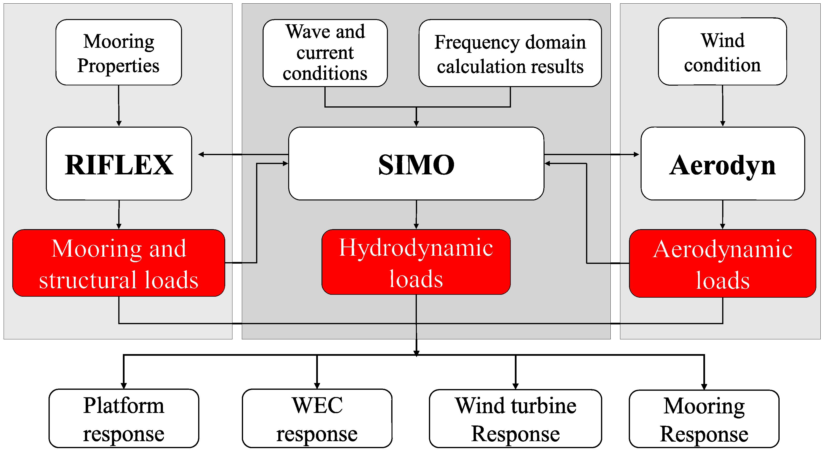
4.3. SIMO-RIFLEX-Aerodyn Combined Simulation System

SIMO is based on potential theory and deals with hydrodynamic loads on rigid floating structures in the time domain, including first-order and second-order wave loads [123]. AeroDyn is an aerodynamic solver program that provides aerodynamic forces and moments on blades based on the theory of Blade Element Momentum (BEM) and Generalized Dynamic Wake (GDW) for simulating aerodynamic loads on wind turbines. RIFLEX is a nonlinear time-domain computational program with finite element formulations that can handle large displacements and rotations [124]. It also can perform coupled analysis, the direct nonlinear time-domain integration scheme for solving the system of equations, including the effects of all interactions. Dynamic models including one or more rigid floating structures combined with mooring and riser systems and arbitrary coupling forces in the time domain can be used to simulate hydrodynamic loads on slender structures (mooring cables) based on Morison’s formulation. The complete simulation system of the structural model is finally solved in the time domain in RIFLEX. The above fully-coupled simulation method (flowchart shown in Figure 12) takes into account the real-time coupling effects of wind and wave, which can realistically simulate the real motion of CWWHDs under environmental loads such as wind and waves to a certain extent.

4.4. Coupled Computational Solution Method Based on the Self-Developed Mathematical Model

Using self-developed mathematical models to establish the correct aeroelastic and hydrodynamic simulation environment is an important method to achieve fully coupled wind and wave calculations. This numerical simulation method is mainly based on MATLAB and other mathematical modeling and calculation software, using the Kane method to establish a comprehensive mathematical model of the multi-body system and embedding the relevant motion control equations, theoretical equations for aerodynamic calculations, and theoretical equations for hydrodynamic calculations into the mathematical model in the form of a programming language. The correct aeroelastic and hydrodynamic simulations are performed in the context of considering wind and wave correlations and misalignments. Due to the lack of a professional aerodynamic environment-generation module, the above simulation methods require wind field generation software such as Turbsim to generate target wind field files to assist in the simulation before fully coupled simulation [112]. The self-developed mathematical model simulation system is highly malleable and can select the appropriate numerical calculation method according to the requirements of computational accuracy and computational cost, and the simulation setup can be designed flexibly according to the characteristics of the target model based on self-developed properties. However, this simulation method has the disadvantage of poor adaptability and needs to be verified and compared with the existing mature simulation system to determine the correctness of the simulation.

4.5. F2A (FAST + ANSYS AQWA) Coupled Simulation System

F2A is a fully coupled aero-hydro-servo-elastic simulation tool based on FAST and ANSYS AQWA. This fully coupled simulation tool can be used for the fully coupled analysis of FOWTs and CWWHDs [125], and its simulation flow is shown in Figure 13. The aero-hydro-servo-elastic simulation function is mainly implemented through the dynamic link library file used for external force calculation in ANSYS AQWA. To perform the wind-wave coupling and multi-body coupling analysis of CWWHDs, the coupling effects of the wind turbine, platform, and the WEC’s motion need to be taken into account simultaneously. The aerodynamic loads acting on the rotor, the elastic response of the blades and the tower, and the servo control are calculated through the aerodynamics module in FAST and input as external forces into ANSYS AQWA for time-domain simulation through the dynamic link library file. The platform position, velocity, and acceleration for each degree of freedom are calculated through the time-domain solver in ANSYS AQWA and transferred to FAST via dynamic link library files as input values for the next time step for calculation. Within each time step, the results of the FAST and ANSYS AWQA simulations are transferred in real-time via dynamic link library files, providing high accuracy for the coupled solution [126]. The above fully-coupled simulation framework has relatively good generality and can be widely used for numerical calculations of conventional CWWHDs. It is worth noting that the calculation results of FAST and ANSYS AQWA need to be converted from the inertial coordinate system to the local coordinate system of the platform during the transfer process, and then the calculation results are transferred to the DLL.

4.6. Simulation with Aerodynamic Calculation Programs Such as FAST and HAWC2, Combined with Frequency Domain Solution Results of Hydrodynamic Software Such as WAMIT, ANSYS AQWA, and HydroD

For some CWWHDs that focus on aerodynamic performance, an aerodynamic calculation software such as FAST, HAWC2, etc., is usually used as the leading simulation tool in the simulation process. Because aerodynamic calculation software such as FAST and HAWC2 have a highly mature simulation system for the coupled dynamic response of wind turbines, aerodynamic load calculation, control, and servo system dynamics calculation [127]. Additional mass, radiation damping, and other key hydrodynamic parameters are obtained in frequency domain calculations in hydrodynamic software such as WAMIT/ANSYS AQWA and added to the hydrodynamic module of the aerodynamic calculation software in the time domain for nonlinear aero-hydro-servo-elastic coupling simulations; the simulation flow chart is shown in Figure 14. Due to the relatively rough calculation accuracy of the hydrodynamic simulation module, the numerical calculation accuracy of the above simulation method in hydrodynamics is relatively low, which is suitable for focusing on the aerodynamic performance of CWWHDs and aerodynamic load analysis.
In summary, to achieve the expected calculation accuracy, the selection of the wind and wave coupling simulation theory and the program should be based on factors such as the structural characteristics of the device, calculation cost, and engineering design stage. Although there is no fully coupled calculation software for CWWHDs, there are many hydrodynamic and aerodynamic solution subprograms that provide the possibility for further research on efficient wind and wave fully coupled calculation software. It is worth noting that for WECs that require special forms of energy acquisition, such as OWCs, the above coupling simulation methods may not be compatible and usually require secondary development.

5. Conclusions and Suggested Directions for Future Research

Offshore wind and wave energy are both green, safe, and renewable energy sources with abundant reserves, thus CWWHDs have superior application prospects. The numerical calculation of wind-wave coupling and multi-body coupling is the key link in the design and development of CWWHDs, as well as the focus and difficulty in the design of CWWHDs. The calculation accuracy and theory of numerical simulation need to be selected and deployed according to the environmental conditions and the characteristics of the device itself. This paper introduces the existing types of offshore wind power devices and wave energy utilization devices based on structural forms and working principles, classifies CWWHDs, reviews the theoretical basis of the CWWHD’s numerical simulation, and summarizes the simulation software, technical methods, and implementation conditions for the multi-body coupling and wind-wave coupling of CWWHDs based on the main features of CWWHD simulation in the existing literature. The gap in the study of numerical simulation methods for the wind-wave coupling and multi-body coupling of CWWHDs is filled. It should be noted that the introduction of the hybrid concept in this review only classifies the structural composition of CWWHDs to emphasize their structural properties and does not summarize and study the existing practical cases.
The following recommendations may help to clarify the future focus of the design and development of CWWHDs and the direction of development of key technologies for the numerical simulation methods:
(1)
Increasing wind and wave energy development in deep and distant marine: wind and wave energy resources in the deep sea are better than those offshore, and the offshore device will greatly reduce the impact on near-shore facilities. Based on the above reasons and the current situation, a floating foundation may be the choice to balance economic efficiency and reliability.
(2)
Promoting research on the conditions and mechanisms of FOWT-WEC synergy: the hysteresis effect between the multi-floating bodies due to the interaction causes the wind turbine to generate more resistance, thus absorbing more wind energy and making the WECs move asynchronously with the semi-submersible platform, which improves the efficiency of the WECs. The synergy is manifested by the self-balancing effect of multi-floating body coupling, which reduces the motion amplitude of the semi-submersible platform. Therefore, it is an important direction for CWWHDs to realize the synergistic effect.
(3)
Advancing the development of integrated aero-hydro-servo-elastic fully coupled simulation software: the coupling among aerodynamic loads, hydrodynamic loads, and structural dynamic loads needs to be solved by combined simulation between different programs at the current stage, which usually has errors. Implementing data transfer and maintaining real-time is a major challenge for the current combined simulation calculation. Therefore, the development of integrated numerical simulation software with high accuracy is necessary for the design of CWWHDs.
(4)
Emphasizing the simulation of the constraints on the relative positions of WECs and OWTs and the simulation of the PTO: the current combined simulation system is not perfect for the simulation of the positional constraints of WECs in the time domain; for example, the limit setting of the heave-type WECs in the existing combined simulation system is difficult to achieve. The simulation of PTO often needs to be conducted by the secondary development of simulation software, which creates some difficulties for the combined simulation. Consequently, it is crucial to complete the simulation of the limitation of the position of the WECs and the PTO reaction force conveniently in the simulation process.
(5)
Promoting the improvement of computational accuracy and computational efficiency of integrated simulation systems: considering the behavior of wind turbine blades usually requires a large number of computational resources and high computational accuracy to support. Based on the existing theory, improving and optimizing the algorithm of the computational model and the method of numerical computation may greatly improve the efficiency of numerical computation on the demand of ensuring computational accuracy.

Author Contributions

Conceptualization, data curation, formal analysis, writing—original draft, F.C.; conceptualization, data curation, formal analysis, writing—original draft, M.Y.; validation, B.L.; supervision and resources, Z.W.; writing—review and editing, L.X.; writing—review and editing, M.H.; Conceptualization, data curation, formal analysis, writing—original draft, H.S. All authors have read and agreed to the published version of the manuscript.

Funding

This research was funded by the National Natural Science Foundation of China (52271297), the Shandong Provincial Natural Science Foundation (ZR2021ZD23), Shandong Provincial Natural Science Foundation (ZR2022ME002), the National Natural Science Foundation of China (52071303), Shandong Provincial Key Research and Development Program (SPKR&DP-MSTIP) (2019JZZY010902), and the Taishan Scholars Program of Shandon Province (ts20190914).

Institutional Review Board Statement

Not applicable.

Informed Consent Statement

Not applicable.

Data Availability Statement

Not applicable.

Conflicts of Interest

The authors declare no conflict of interest.

References

  1. Li, J.; Wang, G.; Li, Z.; Yang, S.; Chong, W.T.; Xiang, X. A review on development of offshore wind energy conversion system. Int. J. Energy Res. 2020, 44, 9283–9297. [Google Scholar] [CrossRef]
  2. Global Wind Report 2022. Available online: https://gwec.net/global-wind-report-2022/ (accessed on 4 April 2022).
  3. Statistical Review of World Energy 2022. Available online: https://www.bp.com/content/dam/bp/business-sites/en/global/corporate/pdfs/energy-economics/statistical-review/bp-stats-review-2022-full-report.pdf (accessed on 12 June 2022).
  4. López, I.; Andreu, J.; Ceballos, S.; De Alegría, I.M.; Kortabarria, I. Review of wave energy technologies and the necessary power-equipment. Renew. Sustain. Energy Rev. 2013, 27, 413–434. [Google Scholar] [CrossRef]
  5. Pérez-Collazo, C.; Greaves, D.; Iglesias, G. A review of combined wave and offshore wind energy. Renew. Sustain. Energy Rev. 2015, 42, 141–153. [Google Scholar] [CrossRef] [Green Version]
  6. Sheng, W. Wave energy conversion and hydrodynamics modeling technologies: A review. Renew. Sustain. Energy Rev. 2019, 109, 482–498. [Google Scholar] [CrossRef]
  7. Chen, G.; Belcher, S.E. Effects of long waves on wind-generated waves. J. Phys. Oceanogr. 2000, 30, 2246–2256. [Google Scholar] [CrossRef]
  8. Astariz, S.; Iglesias, G. Output power smoothing and reduced downtime period by combined wind and wave energy farms. Energy 2016, 97, 69–81. [Google Scholar] [CrossRef]
  9. Kalogeri, C.; Galanis, G.; Spyrou, C.; Diamantis, D.; Baladima, F.; Koukoula, M.; Kallos, G. Assessing the European offshore wind and wave energy resource for combined exploitation. Renew. Energy 2017, 101, 244–264. [Google Scholar] [CrossRef]
  10. McTiernan, K.L.; Sharman, K.T. Review of Hybrid Offshore Wind and Wave Energy Systems. J. Phys. Conf. Ser. 2020, 1452, 012016. [Google Scholar] [CrossRef]
  11. Du, X.; Du, L.; Cai, X.; Hao, Z.; Xie, X.; Wu, F. Dielectric elastomer wave energy harvester with self-bias voltage of an ancillary wind generator to power for intelligent buoys. Energy Convers. Manag. 2022, 253, 115178. [Google Scholar] [CrossRef]
  12. Li, L.; Gao, Y.; Yuan, Z.; Day, S.; Hu, Z. Dynamic response and power production of a floating integrated wind, wave and tidal energy system. Renew. Energy 2018, 116, 412–422. [Google Scholar] [CrossRef]
  13. Zhao, C.; Thies, P.R.; Ye, Q.; Lars, J. System integration and coupled effects of an OWT/WEC device. Ocean Eng. 2021, 220, 108405. [Google Scholar] [CrossRef]
  14. Cong, P.; Teng, B.; Bai, W.; Ning, D.; Liu, Y. Wave power absorption by an oscillating water column (OWC) device of annular cross-section in a combined wind-wave energy system. Appl. Ocean Res. 2021, 107, 102499. [Google Scholar] [CrossRef]
  15. Si, Y.; Chen, Z.; Zeng, W.; Sun, J.; Zhang, D.; Ma, X.; Qian, P. The influence of power-take-off control on the dynamic response and power output of combined semi-submersible floating wind turbine and point-absorber wave energy converters. Ocean Eng. 2021, 227, 108835. [Google Scholar] [CrossRef]
  16. Li, L.; Ruzzo, C.; Collu, M.; Gao, Y.; Failla, G.; Arena, F. Analysis of the coupled dynamic response of an offshore floating multi-purpose platform for the Blue Economy. Ocean Eng. 2020, 217, 107943. [Google Scholar] [CrossRef]
  17. Saeidtehrani, S.; Fazeres-Ferradosa, T.; Rosa-Santos, P.; Taveira-Pinto, F. Review on floating wave-wind energy converter plants: Nonlinear dynamic assessment tools. Sustain. Energy Technol. Assess. 2022, 54, 102753. [Google Scholar] [CrossRef]
  18. Lee, C.F.; Ong, M.C. Combined Wind and Wave Energy System: A Review of Current Technology and State-of-the-Art Simulation Tools. In Proceedings of the 2022 IEEE International Conference on Industrial Engineering and Engineering Management (IEEM), Kuala Lumpur, Malaysia, 7–10 December 2022; pp. 0665–0669. [Google Scholar]
  19. Dong, X.; Li, Y.; Li, D.; Cao, F.; Jiang, X.; Shi, H. A state-of-the-art review of the hybrid wind-wave energy converter. Prog. Energy 2022, 4, 042004. [Google Scholar] [CrossRef]
  20. Gao, Q.; Ertugrul, N.; Ding, B.; Negnevitsky, M. Offshore wind, wave and integrated energy conversion systems: A review and future. In Proceedings of the 2020 IEEE Australasian Universities Power Engineering Conference (AUPEC), Hobart, Australia, 29 November–2 December 2020; pp. 1–6. [Google Scholar]
  21. Wang, Y.; Zhang, L.; Michailides, C.; Wan, L.; Shi, W. Hydrodynamic Response of a Combined Wind–Wave Marine Energy Structure. J. Mar. Sci. Eng. 2020, 8, 253. [Google Scholar] [CrossRef] [Green Version]
  22. Ren, N.; Ma, Z.; Shan, B.; Ning, D.; Ou, J. Experimental and numerical study of dynamic responses of a new combined TLP type floating wind turbine and a wave energy converter under operational conditions. Renew. Energy 2020, 151, 966–974. [Google Scholar] [CrossRef]
  23. Yue, M.; Liu, Q.; Li, C.; Ding, Q.; Cheng, S.; Zhu, H. Effects of heave plate on dynamic response of floating wind turbine Spar platform under the coupling effect of wind and wave. Ocean Eng. 2020, 201, 107103. [Google Scholar] [CrossRef]
  24. Wright, C.; Pakrashi, V.; Murphy, J. Numerical modelling of a combined tension moored wind and wave energy convertor system. In Proceedings of the 12th European Wave and Tidal Energy Conference (EWTEC), Cork, Ireland, 27 August–1 September 2017. [Google Scholar]
  25. Aboutalebi, P.; Garrido, A.J.; M’zoughi, F.; Garrido, I. Stabilization of a Floating Offshore Wind Turbine Using Oscillating Water Columns. In Proceedings of the 2nd Workshop on Wind and Marine Energy (WWME), Online, 17 December 2020; pp. 75–79. [Google Scholar]
  26. Aboutalebi, P.; M’zoughi, F.; Martija, I.; Garrido, I.; Garrido, A.J. Switching control strategy for oscillating water columns based on response amplitude operators for floating offshore wind turbines stabilization. Appl. Sci. 2021, 11, 5249. [Google Scholar] [CrossRef]
  27. Lee, H.; Poguluri, S.K.; Bae, Y.H. Performance analysis of multiple wave energy converters placed on a floating platform in the frequency domain. Energies 2018, 11, 406. [Google Scholar] [CrossRef] [Green Version]
  28. Gao, Z.; Moan, T.; Wan, L.; Michailides, C. Comparative numerical and experimental study of two combined wind and wave energy concepts. J. Ocean Eng. Sci. 2016, 1, 36–51. [Google Scholar] [CrossRef] [Green Version]
  29. Muliawan, M.J.; Karimirad, M.; Gao, Z.; Moan, T. Extreme responses of a combined spar-type floating wind turbine and floating wave energy converter (STC) system with survival modes. Ocean Eng. 2013, 65, 71–82. [Google Scholar] [CrossRef]
  30. Li, J.; Shi, W.; Zhang, L.; Michailides, C.; Li, X. Wind–Wave Coupling Effect on the Dynamic Response of a Combined Wind–Wave Energy Converter. J. Mar. Sci. Eng. 2021, 9, 1101. [Google Scholar] [CrossRef]
  31. Zhang, Y.; Zhao, Y.; Sun, W.; Li, J. Ocean wave energy converters: Technical principle, device realization, and performance evaluation. Renew. Sustain. Energy Rev. 2021, 141, 110764. [Google Scholar] [CrossRef]
  32. Kim, B.-H.; Wata, J.; Zullah, M.A.; Ahmed, M.R.; Lee, Y.-H. Numerical and experimental studies on the PTO system of a novel floating wave energy converter. Renew. Energy 2015, 79, 111–121. [Google Scholar] [CrossRef]
  33. Guo, B.; Wang, T.; Jin, S.; Duan, S.; Yang, K.; Zhao, Y. A Review of Point Absorber Wave Energy Converters. J. Mar. Sci. Eng. 2022, 10, 1534. [Google Scholar] [CrossRef]
  34. Rusu, E.; Onea, F. A review of the technologies for wave energy extraction. Clean Energy 2018, 2, 10–19. [Google Scholar] [CrossRef] [Green Version]
  35. Al Shami, E.; Wang, X.; Zhang, R.; Zuo, L. A parameter study and optimization of two body wave energy converters. Renew. Energy 2019, 131, 1–13. [Google Scholar] [CrossRef]
  36. Aderinto, T.; Li, H. Review on power performance and efficiency of wave energy converters. Energies 2019, 12, 4329. [Google Scholar] [CrossRef]
  37. Suchithra, R.; Ezhilsabareesh, K.; Samad, A. Development of a reduced order wave to wire model of an OWC wave energy converter for control system analysis. Ocean Eng. 2019, 172, 614–628. [Google Scholar] [CrossRef]
  38. Falcão, A.F.d.O.; Justino, P.A.P. OWC wave energy devices with air flow control. Ocean Eng. 1999, 26, 1275–1295. [Google Scholar] [CrossRef]
  39. Nguyen, H.P.; Wang, C.M.; Tay, Z.Y.; Luong, V.H. Wave energy converter and large floating platform integration: A review. Ocean Eng. 2020, 213, 107768. [Google Scholar] [CrossRef]
  40. Martins, J.C.; Goulart, M.M.; Gomes, M.d.N.; Souza, J.A.; Rocha, L.A.O.; Isoldi, L.A.; Dos Santos, E.D. Geometric evaluation of the main operational principle of an overtopping wave energy converter by means of Constructal Design. Renew. Energy 2018, 118, 727–741. [Google Scholar] [CrossRef]
  41. Contestabile, P.; Crispino, G.; Di Lauro, E.; Ferrante, V.; Gisonni, C.; Vicinanza, D. Overtopping breakwater for wave Energy Conversion, Review of state of art, recent advancements and what lies ahead. Renew. Energy 2020, 147, 705–718. [Google Scholar] [CrossRef]
  42. Sunday, K.; Brennan, F. A review of offshore wind monopiles structural design achievements and challenges. Ocean Eng. 2021, 235, 109409. [Google Scholar] [CrossRef]
  43. Micallef, D.; Rezaeiha, A. Floating offshore wind turbine aerodynamics, Trends and future challenges. Renew. Sustain. Energy Rev. 2021, 152, 111696. [Google Scholar] [CrossRef]
  44. Yang, J.; He, Y.-P.; Zhao, Y.-S.; Shao, Y.-L.; Han, Z.-L. Experimental and numerical studies on the low-frequency responses of a spar-type floating offshore wind turbine. Ocean Eng. 2021, 222, 108571. [Google Scholar] [CrossRef]
  45. Ahmed, M.O.; Yenduri, A.; Kurian, V.J. Evaluation of the dynamic responses of truss spar platforms for various mooring configurations with damaged lines. Ocean Eng. 2016, 123, 411–421. [Google Scholar] [CrossRef]
  46. Chuang, T.-C.; Yang, W.-H.; Yang, R.-Y. Experimental and numerical study of a barge-type FOWT platform under wind and wave load. Ocean Eng. 2021, 230, 109015. [Google Scholar] [CrossRef]
  47. Ren, Y.; Venugopal, V.; Shi, W. Dynamic analysis of a multi-column TLP floating offshore wind turbine with tendon failure scenarios. Ocean Eng. 2022, 245, 110472. [Google Scholar] [CrossRef]
  48. Zhang, M.; Li, X.; Tong, J.; Xu, J. Load control of floating wind turbine on a Tension-Leg-Platform subject to extreme wind condition. Renew. Energy 2020, 151, 993–1007. [Google Scholar] [CrossRef]
  49. Aryai, V.; Abbassi, R.; Abdussamie, N.; Salehi, F.; Garaniya, V.; Asadnia, M.; Baksh, A.-A.; Penesis, I.; Karampour, H.; Draper, S. Reliability of multi-purpose offshore-facilities: Present status and future direction in Australia. Process Saf. Environ. Prot. 2021, 148, 437–461. [Google Scholar] [CrossRef] [PubMed]
  50. Hu, J.; Zhou, B.; Vogel, C.; Liu, P.; Willden, R.; Sun, K.; Zang, J.; Geng, J.; Jin, P.; Cui, L. Optimal design and performance analysis of a hybrid system combing a floating wind platform and wave energy converters. Appl. Energy 2020, 269, 114998. [Google Scholar] [CrossRef]
  51. Karimirad, M. Combined Wave-and Wind-Power devices. In Offshore Energy Structures; Springer: Cham, Switzerland, 2014; pp. 105–128. [Google Scholar]
  52. Sun, K.; Yi, Y.; Zheng, X.; Cui, L.; Zhao, C.; Liu, M.; Rao, X. Experimental investigation of semi-submersible platform combined with point-absorber array. Energy Convers. Manag. 2021, 245, 114623. [Google Scholar] [CrossRef]
  53. Wei, Y.; Bechlenberg, A.; Van Rooij, M.; Jayawardhana, B.; Vakis, A.I. Modelling of a wave energy converter array with a non-linear power take-off system in the frequency domain. Appl. Ocean Res. 2019, 90, 101824. [Google Scholar] [CrossRef]
  54. Perez-Collazo, C.; Greaves, D.; Iglesias, G. Hydrodynamic response of the WEC sub-system of a novel hybrid wind-wave energy converter. Energy Convers. Manag. 2018, 171, 307–325. [Google Scholar] [CrossRef]
  55. Zhou, Y.; Ning, D.; Shi, W.; Johanning, L.; Liang, D. Hydrodynamic investigation on an OWC wave energy converter integrated into an offshore wind turbine monopile. Coast. Eng. 2020, 162, 103731. [Google Scholar] [CrossRef]
  56. Sarmiento, J.; Iturrioz, A.; Ayllón, V.; Guanche, R.; Losada, I.J. Experimental modelling of a multi-use floating platform for wave and wind energy harvesting. Ocean Eng. 2019, 173, 761–773. [Google Scholar] [CrossRef]
  57. Ding, S.; Han, D.; Zan, Y. The application of wave energy converter in hybrid energy system. Open Mech. Eng. J. 2014, 8, 936–940. [Google Scholar] [CrossRef]
  58. Moschos, E.; Manou, G.; Dimitriadis, P.; Afentoulis, V.; Koutsoyiannis, D.; Tsoukala, V.K. Harnessing wind and wave resources for a Hybrid Renewable Energy System in remote islands: A combined stochastic and deterministic approach. Energy Procedia 2017, 125, 415–424. [Google Scholar] [CrossRef]
  59. Kamarlouei, M.; Gaspar, J.F.; Calvario, M.; Hallak, T.S.; Mendes, M.J.G.C.; Thiebaut, F.; Soares, C.G. Experimental analysis of wave energy converters concentrically attached on a floating offshore platform. Renew. Energy 2020, 152, 1171–1185. [Google Scholar] [CrossRef] [Green Version]
  60. Kallesøe, B.S. Aero-Hydro-Elastic Simulation Platform for Wave Energy Systems and Floating Wind Turbines; RISO-R-1767(EN); Technical University of Denmark: Kongens Lyngby, Denmark, 2011. Available online: https://www.osti.gov/etdeweb/biblio/1033695 (accessed on 4 April 2022).
  61. Chakrabarti, S.K. Hydrodynamics of Offshore Structures; Springer: Berlin/Heidelberg, Germany, 1987; ISBN 3-540-17319-6. [Google Scholar]
  62. Veritas, N. Environmental Conditions and Environmental Loads; Det Norske Veritas: Oslo, Norway, 2000. [Google Scholar]
  63. Xu, K.; Shao, Y.; Gao, Z.; Moan, T. A study on fully nonlinear wave load effects on floating wind turbine. J. Fluids Struct. 2019, 88, 216–240. [Google Scholar] [CrossRef]
  64. Wendt, F.F.; Robertson, A.; Jonkman, J.M.; Hayman, G. Verification of new floating capabilities in FAST v8. In Proceedings of the 33rd Wind Energy Symposium, Kissimmee, FL, USA, 5–9 January 2015; p. 1204. [Google Scholar]
  65. Ghafari, H.R.; Ghassemi, H.; He, G. Numerical study of the Wavestar wave energy converter with multi-point-absorber around DeepCwind semisubmersible floating platform. Ocean Eng. 2021, 232, 109177. [Google Scholar] [CrossRef]
  66. Papillon, L.; Costello, R.; Ringwood, J.V. Boundary element and integral methods in potential flow theory: A review with a focus on wave energy applications. J. Ocean Eng. Mar. Energy 2020, 6, 303–337. [Google Scholar] [CrossRef]
  67. Chung, J.S. Morison Equation in Practice and Hydrodynamic Validity. Int. J. Offshore Polar Eng. 2018, 28, 11–18. [Google Scholar] [CrossRef]
  68. Fish, P.R.; Dean, R.B.; Heaf, N.J. Fluid-structure interaction in Morison’s equation for the design of offshore structures. Eng. Struct. 1980, 2, 15–26. [Google Scholar] [CrossRef]
  69. Zan, X.; Lin, Z.; Gou, Y. Numerical study on the force distribution on cylindrical structure by internal solitary wave and its prediction with Morison equation. Ocean Eng. 2022, 248, 110701. [Google Scholar] [CrossRef]
  70. Avila, J.P.J.; Adamowski, J.C. Experimental evaluation of the hydrodynamic coefficients of a ROV through Morison’s equation. Ocean Eng. 2011, 38, 2162–2170. [Google Scholar] [CrossRef]
  71. Benitz, M.; Schmidt, D.P.; Lackner, M.; Stewart, G.; Jonkman, J.; Robertson, A. Validation of hydrodynamic load models using CFD for the OC4-DeepCwind semisubmersible. In Proceedings of the ASME 34th International Conference on Ocean, Offshore and Arctic Engineering, St. John’s, NL, Canada, 31 May–5 June 2015. [Google Scholar]
  72. Clement, C.; Kosleck, S.; Lie, T. Investigation of viscous damping effect on the coupled dynamic response of a hybrid floating platform concept for offshore wind turbines. Ocean Eng. 2021, 225, 108836. [Google Scholar] [CrossRef]
  73. Nematbakhsh, A.; Bachynski, E.E.; Gao, Z.; Moan, T. Comparison of wave load effects on a TLP wind turbine by using computational fluid dynamics and potential flow theory approaches. Appl. Ocean Res. 2015, 53, 142–154. [Google Scholar] [CrossRef] [Green Version]
  74. Liu, Y.; Yoshida, S.; Yamamoto, H.; Toyofuku, A.; He, G.; Yang, S. Response characteristics of the DeepCwind floating wind turbine moored by a single-point mooring system. Appl. Sci. 2018, 8, 2306. [Google Scholar] [CrossRef] [Green Version]
  75. Haji, M.N.; Kluger, J.M.; Sapsis, T.P.; Slocum, A.H. A symbiotic approach to the design of offshore wind turbines with other energy harvesting systems. Ocean Eng. 2018, 169, 673–681. [Google Scholar] [CrossRef]
  76. Wilson, J.F. Dynamics of Offshore Structures, 2nd ed.; John Wiley & Sons: Hoboken, NJ, USA, 2003. [Google Scholar]
  77. Jonkman, J.M. Dynamics of offshore floating wind turbines—Model development and verification. Wind Energy: Int. J. Prog. Appl. Wind Power Convers. Technol. 2009, 12, 459–492. [Google Scholar] [CrossRef]
  78. Such, M.; Jimenez-Octavio, J.R.; Carnicero, A.; Lopez-Garcia, O. An approach based on the catenary equation to deal with static analysis of three dimensional cable structures. Eng. Struct. 2009, 31, 2162–2170. [Google Scholar] [CrossRef]
  79. Kreuzer, E.; Wilke, U. Mooring systems—A multibody dynamic approach. Multibody Syst. Dyn. 2002, 8, 279–296. [Google Scholar] [CrossRef]
  80. Matha, D.; Schlipf, M.; Pereira, R.; Jonkman, J. Challenges in simulation of aerodynamics, hydrodynamics, and mooring-line dynamics of floating offshore wind turbines. In Proceedings of the Twenty-First International Offshore and Polar Engineering Conference, Maui, HI, USA, 19–24 June 2011. [Google Scholar]
  81. Hall, M.; Buckham, B.; Crawford, C. Evaluating the importance of mooring line model fidelity in floating offshore wind turbine simulations. Wind Energy 2014, 17, 1835–1853. [Google Scholar] [CrossRef]
  82. Veritas, D.N. DNV-OS-E302: Offshore Mooring Chain; DNV: Høvik, Norway, 2015. [Google Scholar]
  83. Jang, H.-K.; Park, S.; Kim, M.-H.; Kim, K.-H.; Hong, K. Effects of heave plates on the global performance of a multi-unit floating offshore wind turbine. Renew. Energy 2019, 134, 526–537. [Google Scholar] [CrossRef]
  84. Subbulakshmi, A.; Verma, M.; Keerthana, M.; Sasmal, S.; Harikrishna, P.; Kapuria, S. Recent advances in experimental and numerical methods for dynamic analysis of floating offshore wind turbines—An integrated review. Renew. Sustain. Energy Rev. 2022, 164, 112525. [Google Scholar] [CrossRef]
  85. Mahmuddin, F. Rotor blade performance analysis with blade element momentum theory. Energy Procedia 2017, 105, 1123–1129. [Google Scholar] [CrossRef]
  86. Jeon, M.; Lee, S.; Lee, S. Unsteady aerodynamics of offshore floating wind turbines in platform pitching motion using vortex lattice method. Renew. Energy 2014, 65, 207–212. [Google Scholar] [CrossRef]
  87. Øye, S. Dynamic stall simulated as time lag of separation. In Proceedings of the 4th IEA Symposium on the Aerodynamics of Wind Turbines, Enea Casaccia Research Laboratory, Rome, Italy, 20–21 November 1990; p. 28. [Google Scholar]
  88. Snel, J.G.; Schepers, H. Joint Investigation of Dynamic Inflow Effects and Implementation of an Engineering Method. Available online: https://publications.ecn.nl/E/1995/ECN-C--94-107 (accessed on 12 June 2020).
  89. Du, Z.; Selig, M. A 3-D stall-delay model for horizontal axis wind turbine performance prediction. In Proceedings of the 1998 ASME Wind Energy Symposium, Reno, NV, USA, 12–15 January 1998; p. 21. [Google Scholar]
  90. Bhagwat, M.J.; Leishman, J.G. Rotor Aerodynamics During Maneuvering Flight Using a Time-Accurate Free-Vortex Wake. J. Am. Helicopter Soc. 2003, 48, 143–158. [Google Scholar] [CrossRef]
  91. Bouatem, A.; Almers, A.; Boutammachte, N. Load evaluation of horizontal-axis wind turbine rotor using coupled Beddoes near-wake model and free-wake method. Int. J. Energy Environ. Eng. 2013, 4, 35. [Google Scholar] [CrossRef]
  92. Chkir, S. Unsteady loads evaluation for a wind turbine rotor using free wake method. Energy Procedia 2011, 6, 777–785. [Google Scholar] [CrossRef] [Green Version]
  93. Wang, Y.; Sun, X.; Dong, X.; Zhu, B.; Huang, D.; Zheng, Z. Numerical investigation on aerodynamic performance of a novel vertical axis wind turbine with adaptive blades. Energy Convers. Manag. 2016, 108, 275–286. [Google Scholar] [CrossRef]
  94. Lee, H.; Lee, D.-J. Numerical investigation of the aerodynamics and wake structures of horizontal axis wind turbines by using nonlinear vortex lattice method. Renew. Energy 2019, 132, 1121–1133. [Google Scholar] [CrossRef]
  95. Gabor, O.Ş.; Koreanschi, A.; Botez, R.M. A new non-linear vortex lattice method: Applications to wing aerodynamic optimizations. Chin. J. Aeronaut. 2016, 29, 1178–1195. [Google Scholar] [CrossRef] [Green Version]
  96. Li, Y.; Castro, A.M.; Sinokrot, T.; Prescott, W.; Carrica, P.M. Coupled multi-body dynamics and CFD for wind turbine simulation including explicit wind turbulence. Renew. Energy 2015, 76, 338–361. [Google Scholar] [CrossRef]
  97. Churchfield, M.J.; Lee, S.; Michalakes, J.; Moriarty, P.J. A numerical study of the effects of atmospheric and wake turbulence on wind turbine dynamics. J. Turbul. 2012, 13, N14. [Google Scholar] [CrossRef]
  98. Bhushan, S.; Walters, D.K. A dynamic hybrid Reynolds-averaged Navier Stokes–Large eddy simulation modeling framework. Phys. Fluids 2012, 24, 015103. [Google Scholar] [CrossRef]
  99. Heinz, S.; Mokhtarpoor, R.; Stoellinger, M. Theory-based Reynolds-averaged Navier–Stokes equations with large eddy simulation capability for separated turbulent flow simulations. Phys. Fluids 2020, 32, 065102. [Google Scholar] [CrossRef]
  100. Yu, G.; Shen, X.; Zhu, X.; Du, Z. An insight into the separate flow and stall delay for HAWT. Renew. Energy 2011, 36, 69–76. [Google Scholar] [CrossRef]
  101. Nicolle, J.; Morissette, J.F.; Giroux, A.M. Transient CFD simulation of a Francis turbine startup. In IOP Conference Series: Earth and Environmental Science; IOP Publishing: Bristol, UK, 2012; Volume 15, p. 062014. [Google Scholar]
  102. Cheng, Z.; Wen, T.R.; Ong, M.C.; Wang, K. Power performance and dynamic responses of a combined floating vertical axis wind turbine and wave energy converter concept. Energy 2019, 171, 190–204. [Google Scholar] [CrossRef]
  103. Mazarakos, T.; Konispoliatis, D.; Katsaounis, G.; Polyzos, S.; Manolas, D.; Voutsinas, S.; Soukissian, T.; Mavrakos, S.A. Numerical and experimental studies of a multi-purpose floating TLP structure for combined wind and wave energy exploitation. Mediterr. Mar. Sci. 2019, 20, 745–763. [Google Scholar] [CrossRef] [Green Version]
  104. Ren, N.; Gao, Z.; Moan, T.; Wan, L. Long-term performance estimation of the Spar–Torus-Combination (STC) system with different survival modes. Ocean Eng. 2015, 108, 716–728. [Google Scholar] [CrossRef]
  105. Wan, L.; Gao, Z.; Moan, T.; Lugni, C. Comparative experimental study of the survivability of a combined wind and wave energy converter in two testing facilities. Ocean Eng. 2016, 111, 82–94. [Google Scholar] [CrossRef] [Green Version]
  106. Muliawan, M.J.; Karimirad, M.; Moan, T.; Gao, Z. STC (Spar-Torus Combination): A combined spar-type floating wind turbine and large point absorber floating wave energy converter—Promising and challenging. In Proceedings of the International Conference on Offshore Mechanics and Arctic Engineering, Rio de Janeiro, Brazil, 1–6 July 2012; Volume 44946, pp. 667–676. [Google Scholar]
  107. Li, Q.; Michailides, C.; Gao, Z.; Moan, T. A comparative study of different methods for predicting the long-term extreme structural responses of the combined wind and wave energy concept semisubmersible wind energy and flap-type wave energy converter. Proc. Inst. Mech. Eng. Part M J. Eng. Marit. Environ. 2018, 232, 85–96. [Google Scholar] [CrossRef]
  108. Michailides, C.; Gao, Z.; Moan, T. Response analysis of the combined wind/wave energy concept SFC in harsh environmental conditions. In Proceedings of the RENEW2014 1st International Conference on Renewable Energies Offshore, Lisbon, Portugal, 24–26 November 2014. [Google Scholar]
  109. Luan, C.; Michailides, C.; Gao, Z.; Moan, T. Modeling and analysis of a 5 MW semi-submersible wind turbine combined with three flap-type wave energy converters. In Proceedings of the International Conference on Offshore Mechanics and Arctic Engineering, San Francisco, CA, USA, 8–13 June 2014; Volume 45547, p. V09BT09A028. [Google Scholar]
  110. Karimirad, M.; Koushan, K. WindWEC: Combining wind and wave energy inspired by hywind and wavestar. In Proceedings of the 2016 IEEE International Conference on Renewable Energy Research and Applications (ICRERA), Birmingham, UK, 20–23 November 2016; pp. 96–101. [Google Scholar]
  111. Aboutalebi, P.; M’zoughi, F.; Garrido, I.; Garrido, A.J. Performance analysis on the use of oscillating water column in barge-based floating offshore wind turbines. Mathematics 2021, 9, 475. [Google Scholar] [CrossRef]
  112. Mitra, A.; Sarkar, S.; Chakraborty, A.; Das, S. Sway vibration control of floating horizontal axis wind turbine by modified spar-torus combination. Ocean Eng. 2021, 219, 108232. [Google Scholar] [CrossRef]
  113. Hanssen, J.E.; Margheritini, L.; O’sullivan, K.; Mayorga, P.; Martinez, I.; Arriaga, A.; Agos, I.; Steynor, J.; Ingram, D.; Hezari, R. Design and performance validation of a hybrid offshore renewable energy platform. In Proceedings of the 2015 IEEE Tenth International Conference on Ecological Vehicles and Renewable Energies (EVER), Monte Carlo, Monaco, 31 March–2 April 2015; pp. 1–8. [Google Scholar]
  114. Bachynski, E.E.; Moan, T. Point absorber design for a combined wind and wave energy converter on a tension-leg support structure. In Proceedings of the International Conference on Offshore Mechanics and Arctic Engineering, Nantes, France, 9–14 June 2013; Volume 55423, p. V008T09A025. [Google Scholar]
  115. Chen, W.; Gao, F.; Meng, X.; Chen, B.; Ren, A. W2P: A high-power integrated generation unit for offshore wind power and ocean wave energy. Ocean Eng. 2016, 128, 41–47. [Google Scholar] [CrossRef]
  116. Chen, Z.; Yu, J.; Sun, J.; Tan, M.; Yang, S.; Ying, Y.; Qian, P.; Zhang, D.; Si, Y. Load Reduction of Semi-Submersible Floating Wind Turbines by Integrating Heaving-Type Wave Energy Converters with Bang-Bang Control. Front. Energy Res. 2022, 10, 929307. [Google Scholar] [CrossRef]
  117. Li, L.; Yuan, Z.; Gao, Y. Dynamic response and power production of an integrated offshore renewable energy system. In Proceedings of the 28th International Ocean and Polar Engineering Conference, Sapporo, Japan, 10–15 June 2018. [Google Scholar]
  118. Li, L.; Cheng, Z.; Yuan, Z.; Gao, Y. Short-term extreme response and fatigue damage of an integrated offshore renewable energy system. Renew. Energy 2018, 126, 617–629. [Google Scholar] [CrossRef] [Green Version]
  119. Ren, N.; Ma, Z.; Fan, T.; Zhai, G.; Ou, J. Experimental and numerical study of hydrodynamic responses of a new combined monopile wind turbine and a heave-type wave energy converter under typical operational conditions. Ocean Eng. 2018, 159, 1–8. [Google Scholar] [CrossRef]
  120. Li, Y.; Ong, M.C.; Wang, K.; Li, L.; Cheng, Z. Power performance and dynamic responses of an integrated system with a semi-submersible wind turbine and four torus-shaped wave energy converters. Ocean Eng. 2022, 259, 111810. [Google Scholar] [CrossRef]
  121. Jonkman, J.; Butterfield, S.; Musial, W.; Scott, G. Definition of a 5-MW Reference Wind Turbine for Offshore System Development; National Renewable Energy Lab. (NREL): Golden, CO, USA, 2009. [Google Scholar]
  122. Zhai, Y.; Xu, C.; Zhao, H.; Wang, W.; Li, X. Dynamic Analysis of an Integrated Floating Structure Consisting of a Barge Offshore Wind Turbine with an Aquaculture Cage. In Proceedings of the 32nd International Ocean and Polar Engineering Conference, Shanghai, China, 5–10 June 2022. [Google Scholar]
  123. Cheng, Z.; Madsen, H.A.; Gao, Z.; Moan, T. A fully coupled method for numerical modeling and dynamic analysis of floating vertical axis wind turbines. Renew. Energy 2017, 107, 604–619. [Google Scholar] [CrossRef]
  124. Oguz, E.; Clelland, D.; Day, A.H.; Incecik, A.; López, J.A.; Sánchez, G.; Almeria, G.G. Experimental and numerical analysis of a TLP floating offshore wind turbine. Ocean Eng. 2018, 147, 591–605. [Google Scholar] [CrossRef] [Green Version]
  125. Yang, Y.; Bashir, M.; Li, C.; Wang, J. Investigation on mooring breakage effects of a 5 MW barge-type floating offshore wind turbine using F2A. Ocean Eng. 2021, 233, 108887. [Google Scholar] [CrossRef]
  126. Yang, Y.; Bashir, M.; Michailides, C.; Li, C.; Wang, J. Development and application of an aero-hydro-servo-elastic coupling framework for analysis of floating offshore wind turbines. Renew. Energy 2020, 161, 606–625. [Google Scholar] [CrossRef]
  127. Nielsen, F.G.; Hanson, T.D.; Skaare, B. Integrated Dynamic Analysis of Floating Offshore Wind Turbines. In Proceedings of the 25th International Conference on Offshore Mechanics and Arctic Engineering, Hamburg, Germany, 4–9 June 2006; pp. 671–679. [Google Scholar]
Figure 1. Schematic diagram of oscillating body type WEC.
Jmse 11 00212 g001
Figure 2. Schematic diagram of oscillating water column WEC.
Jmse 11 00212 g002
Figure 3. Schematic diagram of overtopping WEC.
Jmse 11 00212 g003
Figure 4. Schematic diagram of fixed offshore wind turbine.
Jmse 11 00212 g004
Figure 5. Schematic diagram of floating offshore wind turbine.
Jmse 11 00212 g005
Figure 6. Velocity triangle of the blade element cross-section and forces on the airfoil.
Jmse 11 00212 g006
Figure 7. Vortex lattice distribution of blade lifting surface.
Jmse 11 00212 g007
Figure 8. Diagram of high wind speed blade trailing edge flow separation.
Jmse 11 00212 g008
Figure 9. Schematic diagram of the fully-coupled numerical simulation flow of CWWHDs.
Jmse 11 00212 g009
Figure 10. Schematic diagram of wind-wave coupling simulation flow by adding constant aerodynamic loads.
Jmse 11 00212 g010
Figure 11. Schematic diagram of wind-wave coupling simulation flow by using dynamic link library in ANSYS AQWA.
Jmse 11 00212 g011
Figure 12. Schematic diagram of wind-wave coupling simulation flow through SIMO-RIFLEX-Aerodyn combined simulation.
Jmse 11 00212 g012
Figure 13. Schematic diagram of the fully coupled simulation process of F2A (FAST + ANSYS AQWA).
Jmse 11 00212 g013
Figure 14. Schematic diagram of the wind and wave coupling simulation process with the aerodynamic calculation program as the main body and the solution results in the hydrodynamic frequency domain.
Jmse 11 00212 g014
Table 1. The research content of different reviews in the domain of CWWHDs.
LiteraturePublished TimeResearch Content
Hybrid
Concepts
Numerical
Calculation Tools
Environmental Load
Assessment Methodology
Detailed Coupling
Simulation Methods
[17]2022
[18]2022
[19]2022
[10]2020
[20]2020
This Review
Table 2. The fundamental theory of wind and wave coupling calculations.
HydrodynamicsStructural DynamicsAerodynamics
Morrison Equation (ME)Dynamic Analysis Theory (Dyn)Blade Element Momentum Theory (BEM)
Potential Flow Theory (PF)Finite Element Method (FEM)Vortex Wake Method (VWM)
Computational Fluid Dynamics (CFD)Quasi-Static Method (QS)Computational Fluid Dynamics (CFD)
Table 3. Combined simulation methods for CWWHDs.
Name of the DeviceStructural FormSimulation Solution
A 5-MW braceless wind turbine with a heave-type WEC [21]Semi + Heave-type WECANSYS AQWA + External dynamic link library
DWC (DeepCwind-Wavestar-Combined) [15]Semi + OBANSYS AQWA + External dynamic link library
A system of three identical OWC devices and TLP [103]TLP + OWCIn-house code (HAMVAB) + hGAST
STC (Spar-Torus Combination) [28,29,104,105,106]Spar + Torus-shaped
WEC
HydroD + SIMO + Mean constant thrust load/RIFLEX + SIMO + Aerodyn
A hybrid wind-wave energy concept includes WECs by point-absorbers and DeepCwind [65]Semi + OBOnly ANSYS AQWA
SFC [28,107,108,109]Semi + Flap-type WECRIFLEX + SIMO + Aerodyn
WindWEC [110]Semi + OBRIFLEX + SIMO + WAMIT
Barge-based floating offshore wind turbine with four OWCs [111]Barge + OWCWAMIT + FAST
TWWC((TLP-WT-WEC-Combination) [22]TLP + Heave-type WECANSYS AQWA + Equivalent thrust and torque loading
The coupled concept of the OWT and the heaving buoy WEC [13,26]OWT + Heaving buoy WECANSYS AQWA + OrcaFlex
A combined concept combing a heave-type WEC with a semisubmersible floating wind turbine [30]Semi + Heave-type WECF2A (ANSYS AQWA + FAST)
A conceptual 10 MW-class wave-offshore wind hybrid power generation system [27]Semi + OBHARP-CHARM3D-WAMIT
MSTC (Modified Spar-torus Combination) [112]Spar + Torus-type WECA self-developed mathematical model based on Matlab + Turbsim + FAST
TWindWave [24]TLP + OBOrcaFlex + ANSYS AQWA
MPP (Multi-Purpose Platform) [16]TLP + OWCRIFLEX + SIMO + WADAM\ANSYS AQWA
W2power [113]Semi + OBRIFLEX + SIMO
TLPWT with 3-point absorber WECs with hinged guides [114]TLP + OBSIMO + RIFLEX + Aerodyn
A high-power integrated generation unit for offshore wind power and ocean wave energy (W2P) [115]Semi + OBOnlyANSYS AQWA
The coupled concept of the barge platform and OWC [25]Barge + OWCWAMIT + FAST
A novel hybrid wind-wave energy platform consisting of a semi-submersible FOWT and three heaving-type WECs [116]Semi + Heaving-type WECF2A (FAST + ANSYS AQWA)
HWNC (Hywind-Wavebob-NACA Combination) [12,117,118]Spar + Heaving-type WECWind-SKLOE + WEC-Sim
MWWC (Monopile-WT-WEC- Combination) [119]Monopile + Heave-type WECANSYS AQWA + Aerodyn
CTC (CSC-torus-combination) [120]Semi + Torus-shaped WECHydroD + SIMO + RIFLEX
Disclaimer/Publisher’s Note: The statements, opinions and data contained in all publications are solely those of the individual author(s) and contributor(s) and not of MDPI and/or the editor(s). MDPI and/or the editor(s) disclaim responsibility for any injury to people or property resulting from any ideas, methods, instructions or products referred to in the content.

