Article

Design of Anti-Capsize Ship for Patrol Vessel with the Self-Righting Moment

1
Department of Naval Architecture, Faculty of Engineering, Universitas Diponegoro, Semarang 50275, Indonesia
2
Department of Naval Architecture, Ocean, and Marine Engineering, University of Strathclyde, Glasgow G1 1XQ, UK
*
Author to whom correspondence should be addressed.
J. Mar. Sci. Eng. 2023, 11(1), 133; https://doi.org/10.3390/jmse11010133
Submission received: 26 November 2022 / Revised: 13 December 2022 / Accepted: 25 December 2022 / Published: 6 January 2023
(This article belongs to the Section Ocean Engineering)

Abstract

:
The patrol boat is one of the critical aspects for archipelago countries, such as Indonesia, to supervise and maintain the sea border. Due to rough sea conditions, the patrol boat could lose its stability due to the loss of a self-righting roll moment in severe waves. One of the most challenging aspects is to ensure the sufficient stability of the patrol boat during rough conditions. Another challenge is to design a boat that has a self-righting moment during rolling in extreme conditions. This paper examines the design of an anti-capsize ship by improving the self-righting moment with different deck houses height. The rough condition is described when the boat experiences a roll angle of 170°. The principal dimensions of the patrol boat, i.e., Lpp, B, H, T, are 13.0 m, 4.2 m, 2.19 m, and 1.15 m, respectively. Four different deck house heights are compared to obtain the best self-righting roll moment with a height increment of 0.1 m. The physical model is implemented with ship model 1:27.4. In addition, computational fluid dynamics (CFD) is also used to support the proof of the existence of the self-righting roll moment. It is revealed that the center of gravity and buoyancy are essential parameters to acquire the self-righting moment. The height of the deckhouse improves the center of the metacenter, which influences the righting arm of ship stability. The results show that our ship design has a self-righting moment during heel at 180°.

1. Introduction

The patrol boat is essential for archipelago countries such as Indonesia to supervise and maintain the sea border. Many violations have occurred in the past, such as illegal fishing in the Natuna sea and border violations with neighboring countries. This indicates that the patrol vessel is an essential tool in Indonesia as a maritime and archipelago country. Patrol vessels operate in the Exclusive Economic Zone (EEZ) area, and, sometimes, sea conditions will be rough.
In harsh conditions, patrol vessels will experience strong winds and waves that affect the ship’s stability. The ship will also experience an extreme roll motion that can be over 90°. In this situation, the vessel can be capsized due to the loss of a self-righting roll moment.
A study of patrol vessels with interceptors was carried out with the CFD method and showed that the resistance could be decreased by adding an interceptor [1]. A study of the aerodynamic load on patrol vessels using computational fluid dynamics (CFD) was conducted with an OpenFOAM solver [2]. The study shows that CFD can provide reliable aerodynamic load predictions for high-speed vessels. An analysis of the survivability of ocean patrol vessels related to survivability, redundancy and technical endurance was performed using Monte Carlo analysis [3].
The effects of side keels on patrol vessel safety in astern waves were studied by Maimum et al. [4]. A study of the hybrid propulsion system Diesel Mechanical and Diesel Electric Propulsion (DMP and DEP) for a trimaran fast patrol boat was carried out by Windyandari and Wahyudi [5]. Moreover, a flat-hull ship was used as a patrol vessel in concept design [6]. A ship with a self-righting moment was studied for SAR purposes and patrol [7,8]. The study indicates that the capacity for a self-righting moment still exists in rolling above 180°. Rolling is one of the most dangerous motions on a ship; if the ship loses the self-righting moment during rolling, as a result, the ship will capsize.
Many studies have been performed for ship rolling in extreme conditions, and numerical methods such as computational fluid dynamics (CFD) are often used in ship stability. CFD prediction of full-scale ship parametric rolling in heading waves was performed by Liu et al. [9]. The study showed that CFD has the capability to reproduce ships in the wave.
The application of CFD to predict the roll response of damaged ships during quasi-steady flooding in beam waves was conducted by Xu et al. [10]. Full-scale self-propulsion computations using a discretized propeller for the KRISO container ship KCS was carried out by Castro et al. [11]. The results showed that CFD had good agreement with the experiment.
CFD validation and grid sensitivity studies of full-scale ship self-propulsion were carried out by Jasak et al. [12]. Overset grids in OpenFOAM with application to KCS self-propulsion and maneuvering were described by Shen et al. [13]. The study showed that the naoeFOAM-SJTU solver could reproduce the self-propelled phenomenon. Verification and validation of the flow around the KVLCC2 tanker at a model and full scale was performed by Pereira et al. [14], and a numerical investigation of the 6-DOF seakeeping performance of the KCS containership was performed by Lungu [15].
Prediction of the pitch and heave motions in regular waves for the DTMB 5415 ship using CFD was compared with the use of MMG [16], and the study showed CFD results similar to those of the MMG model. It can be concluded that CFD has good accuracy for ship hydrodynamics prediction. In this paper, a self-righting moment in rolling above 180° was considered both in the physical model and CFD.
The present work was conducted to study the effect of the self-righting moment in a high-roll-angle condition. In this condition, the ship undergoes dynamic conditions because of the change in the center of gravity and buoyancy. The ship could lose the self-righting moment if there is a negative roll moment in the upright ship in the original condition.
The patrol vessel has a small breadth, making the self-righting roll moment smaller and linear with a breadth ratio. Moreover, patrol vessels operate in nearshore regions that sometimes experience rough conditions, which could lead to extreme roll motion. In this study, the patrol vessel was designed with a self-righting moment in rolling up to 180°. The design of the ship had four different heights of the deckhouse, with increments of 10 cm to increase the roll moment in the heeling condition.
One of the aims of this study was to select the ship design that has the highest righting roll moment; thus, the ship can return to the upright position after heeling with the high angle. Another aim was to prove the existence of the self-righting roll moment on the boat by conducting an experimental test of the 1:27.4 physical model scale. Moreover, the numerical approach of computational fluid dynamics (CFD) was used to support the physical model results.

2. Methods

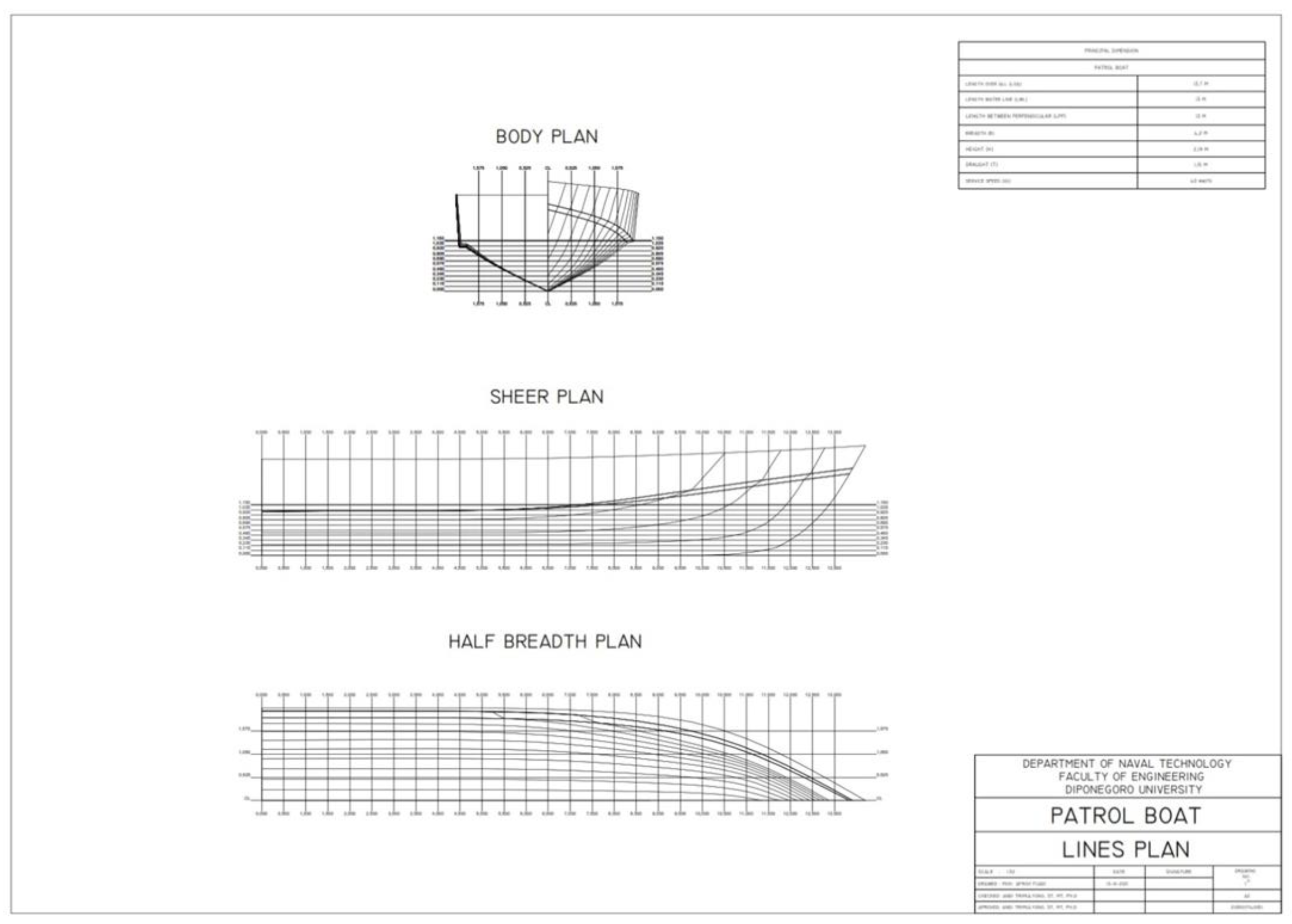
The physical model of the ship design was first created by modeling a ship with a basic design. Figure 1 shows the body plan of a ship for patrol dan search and rescue (SAR). The body plan indicates a view of the ship in the longitudinal (side and bottom view) and transverse view (front view). The ship was designed with a single chine to increase the ship speed, which it used as a lift force due to the spray effect of water passing the hull, which bends around the side of the ship. In this study, the ship was designed for fast patrol. This is another reason that chine was used in the ship.
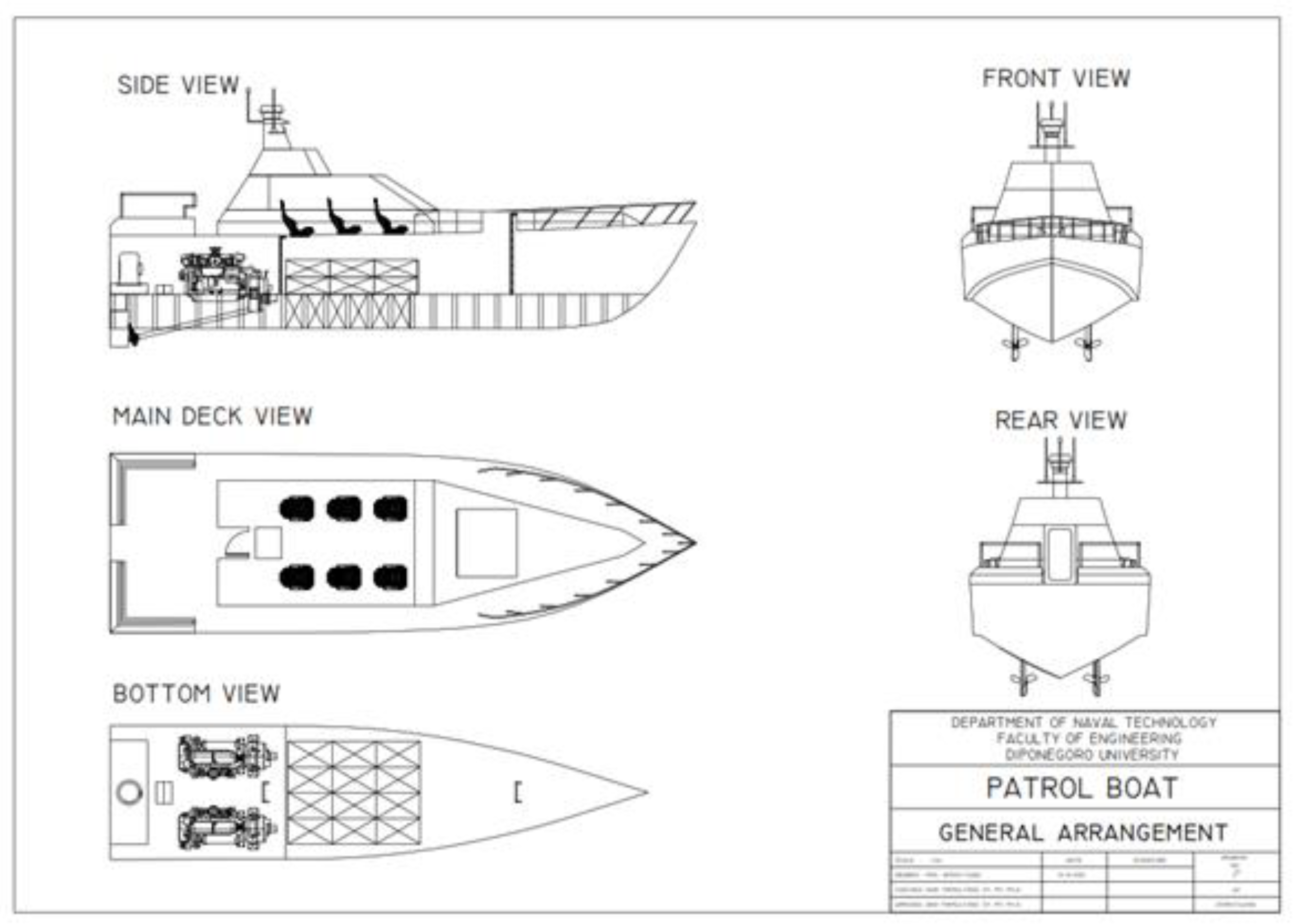
Table 1 indicates the principal dimensions of the ship, where LBP is the length between perpendiculars, B is the ship breadth, H is the ship height, and T is the ship draft. The ship dimensions were based on a Barracuda vessel (https://www.safehavenmarine.com/barracuda (accessed on 18 January 2022)) with a self-righting capability. The ship was designed for six passengers with six pieces of baggage and cargo. Detailed information of the ship’s general arrangement can be seen in Figure 2.
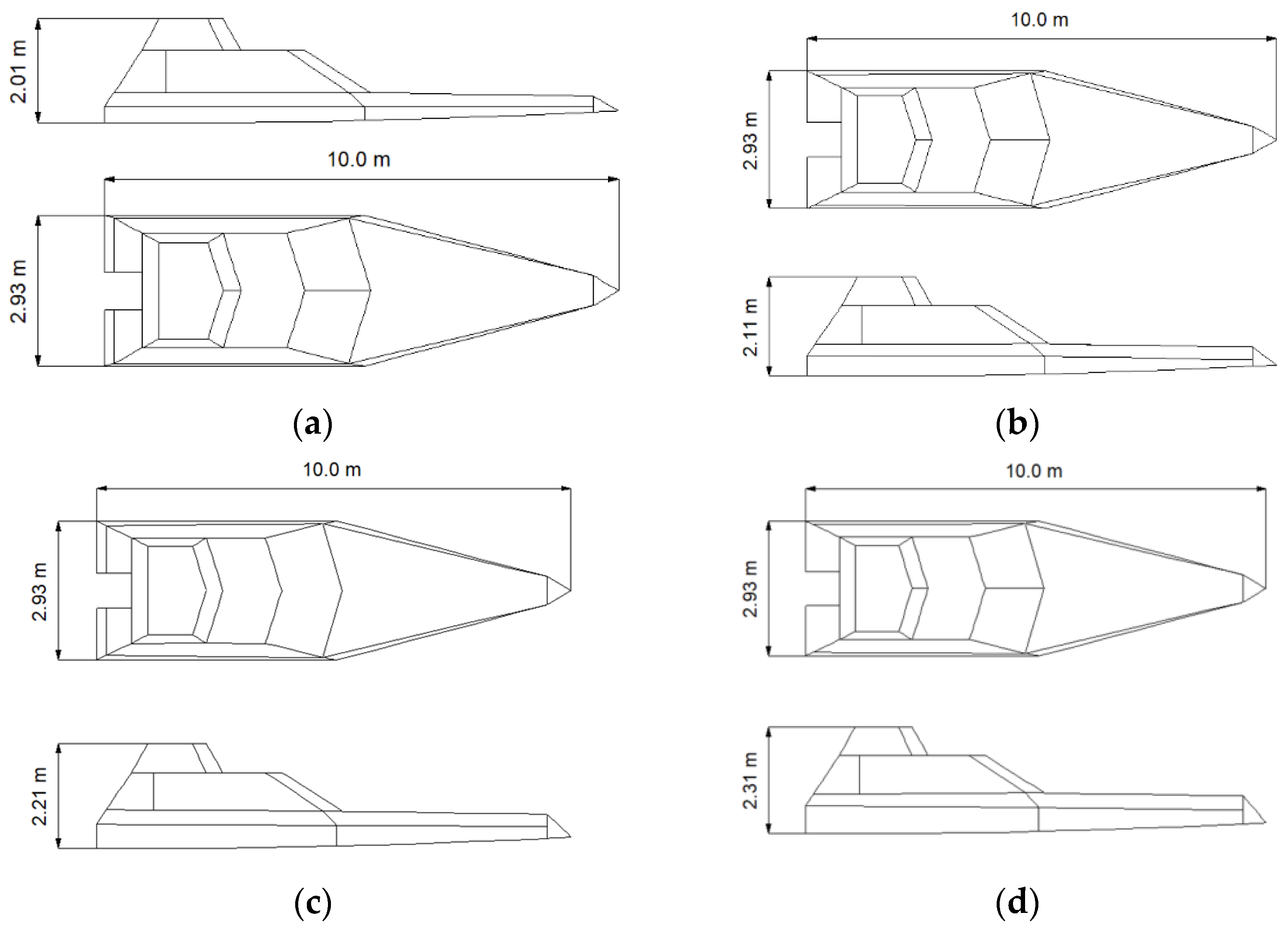
The height of deckhouse variation was achieved with increments of 10 cm to increase the height of the ship’s metacenter. Figure 3 illustrates four deckhouses with a height increment of 10 cm. The deckhouse was assumed to be watertight. This assumption was made to ensure that when the boat was heeling, water could not enter the boat and cause the ship to capsize due to flooding.
Table 2 describes the load case condition of the boat, used to calculate the heeling arm for several conditions—for instance, lightweight, zero cargo, half of the cargo and the full load condition. Table 3 shows the dimensions of the physical model of a ship. This model was tested in a mini towing tank in the Department of Naval Architecture, Universitas Diponegoro.
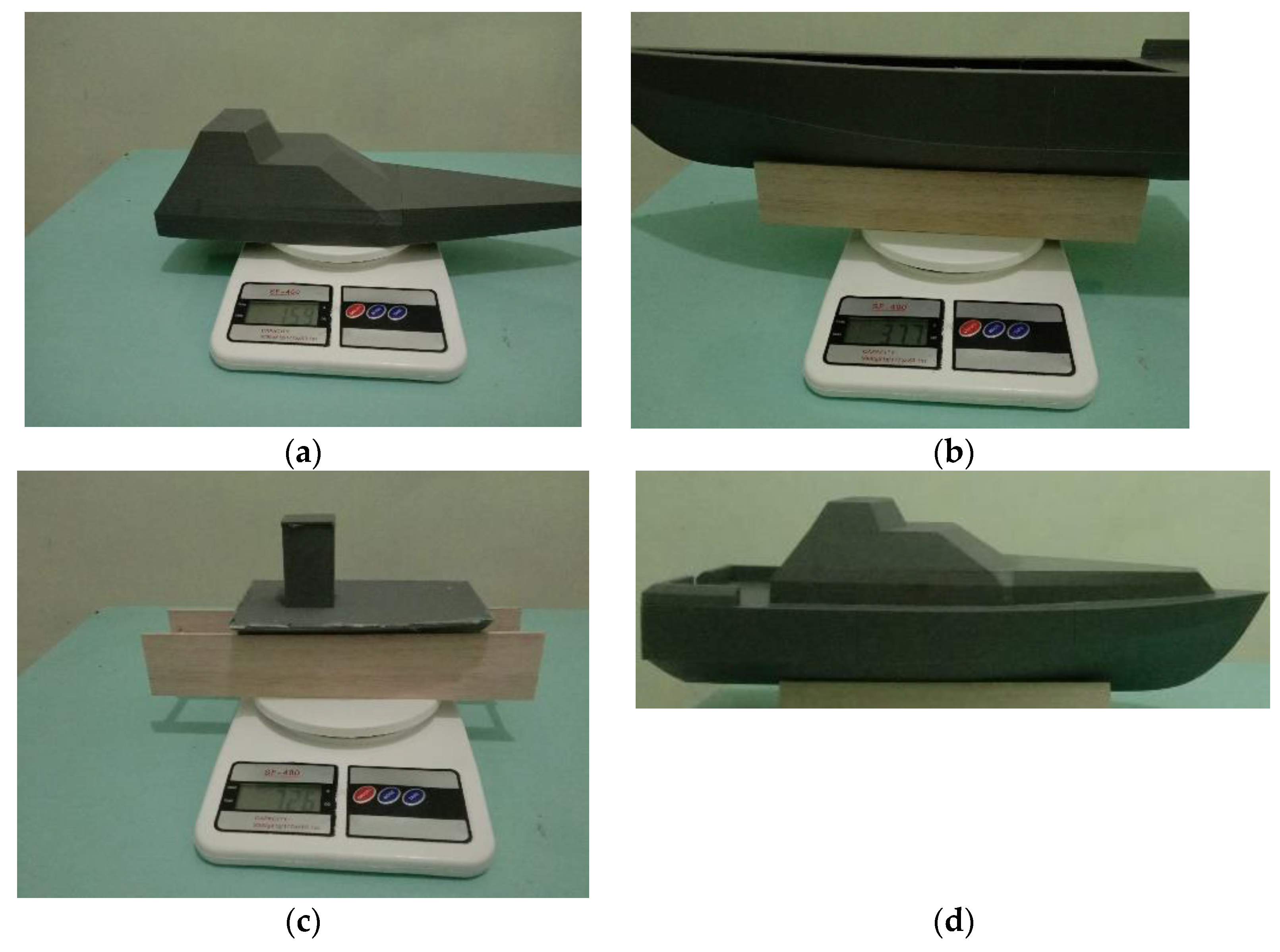
Due to the limitation of the width of the tank, a scale of 1:27.4 was chosen in this study. Figure 4 shows a physical model of a ship with a solid ballast. Solid ballast 1262 gr was used to obtain a similar full-scale ship. Table 4 shows the calculation of the center of gravity of the ship model. The calculation of the center of gravity is shown in Table 5. It has a difference of 6.15% for longitudinal center gravity and 9.20 for the keel to gravity.
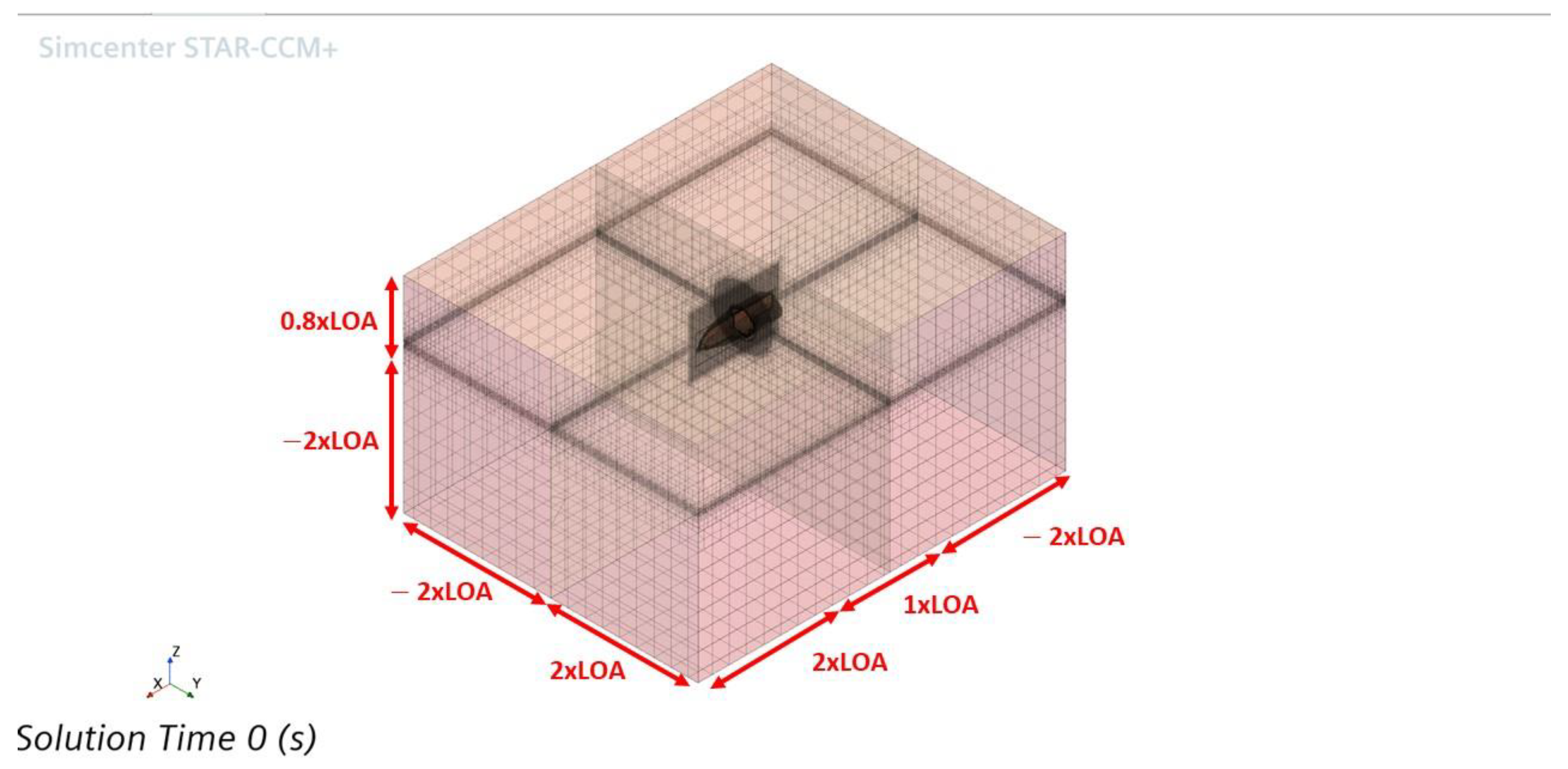
Figure 5 illustrates the computational domain for CFD setup; the self-righting moment was simulated with roll decay analysis to prove that the boat could return to an upright condition after rolling at a high angle. In this study, roll decay simulation was conducted using commercial CFD software, Siemens Star-CCM+ version 16.04.
Figure 5 shows the fluid domain size for this simulation, which is -Lpp × 2Lpp, -Lpp < y < Lpp and -Lpp < z < 0.4 Lpp. The size of the box for free surface refinement on the background region is -2Lpp × 2Lpp, -Lpp < y < Lpp, and -(1.2Hw × 0.5) < z < (1.2Hw × 0.5). For the overset region, the height of the box for free surface refinement is −0.5 m < z, 1.00 m. This size covers the ship height.
The finite volume method (FVM) was used to discretize the integral form of the Unsteady Reynolds-Averaged Navier–Stokes (URANS) equations. A second-order convection scheme was used for the convective terms. For the time-domain solution, a first-order temporal discretization was used. The continuity and momentum were linked using a predictor–corrector scheme. The flow equations were solved in an uncoupled manner. The overall solution procedure was solved using the Semi-Implicit Method for Pressure Linked Equations (SIMPLE) algorithm.
The turbulence effect in the boundary layer region was modeled using the Shear-Stress Transport (SST) [17], which blends a k-ɛ model in the far field with a k-ω model near the wall. The all-y+ treatment scheme was used to treat the boundary layer region either for fine grids (when y+ < 5) or for coarse grids (when y+ > 30). To capture the free surface, the Volume of Fluid (VoF) method, introduced by Hirt and Nichols [18], was used. VoF defines two phases of the fluid (water and air) by assigning a scalar value of 0 to air and 1 to water in each cell. Then, value of the interface between two fluid phases (the cells contain water and air) is 0.5. The flat wave modules with zero velocity were used to represent fluid in the computational domain without waves when the boat was at zero velocity.
The dynamic fluid body interaction (DFBI) module was used to capture the two degrees of freedom of the boat in the roll decay simulation, which are roll and heave. This module computes the exciting forces, moment and gravitational force acting on the hull surface and solves the governing equation to determine the new position in each time step.
Figure 6 shows the two regions, overset and background, that are used in this paper. Overlap refinement was employed between two regions to ensure that the roll decay simulation was smooth. Another refinement was located near to the free surface, called free surface refinement, to distinguish the water and air phases with high precision.
For the generation of the mesh, the automatic mesh tool in Star CCM+ was employed, called a trimmed cell mesh, and a surface remesher. This tool uses the mesh Cartesian cut cell method. The total thickness of the prism layer around the hull surface is 1.095 × 10⁻³ m, which is divided into six layers of prismatic cells with the stretching factor of 1.2 and results in the first layer of 1.104 × 10⁻⁴ m.
The total cells of the generated mesh amount to 4,213,084 cells. For Grid Convergence Index (GCI) analysis, the generated mesh, later referred to as the fine mesh configuration, was coarsened with the refinement ratio √2, and then it was denoted the medium mesh configuration. The total cells of this configuration amounted to 1,592,881 cells. This configuration was then coarsened again with the same ratio to achieve a coarse mesh configuration and resulted in a total number of cells of 709,885.
The choice of time step in this study was based on the ITTC recommendation. It is recommended for periodic phenomena, such as roll decay, and the time step should be at least 100 per period. In this case, the natural roll period is approximately 0.56 s. The minimum time step based on the ITTC recommendation is 0.0056. However, in this study, CFD simulation used a time step of 0.004 s, which was lower than the ITTC recommendation.
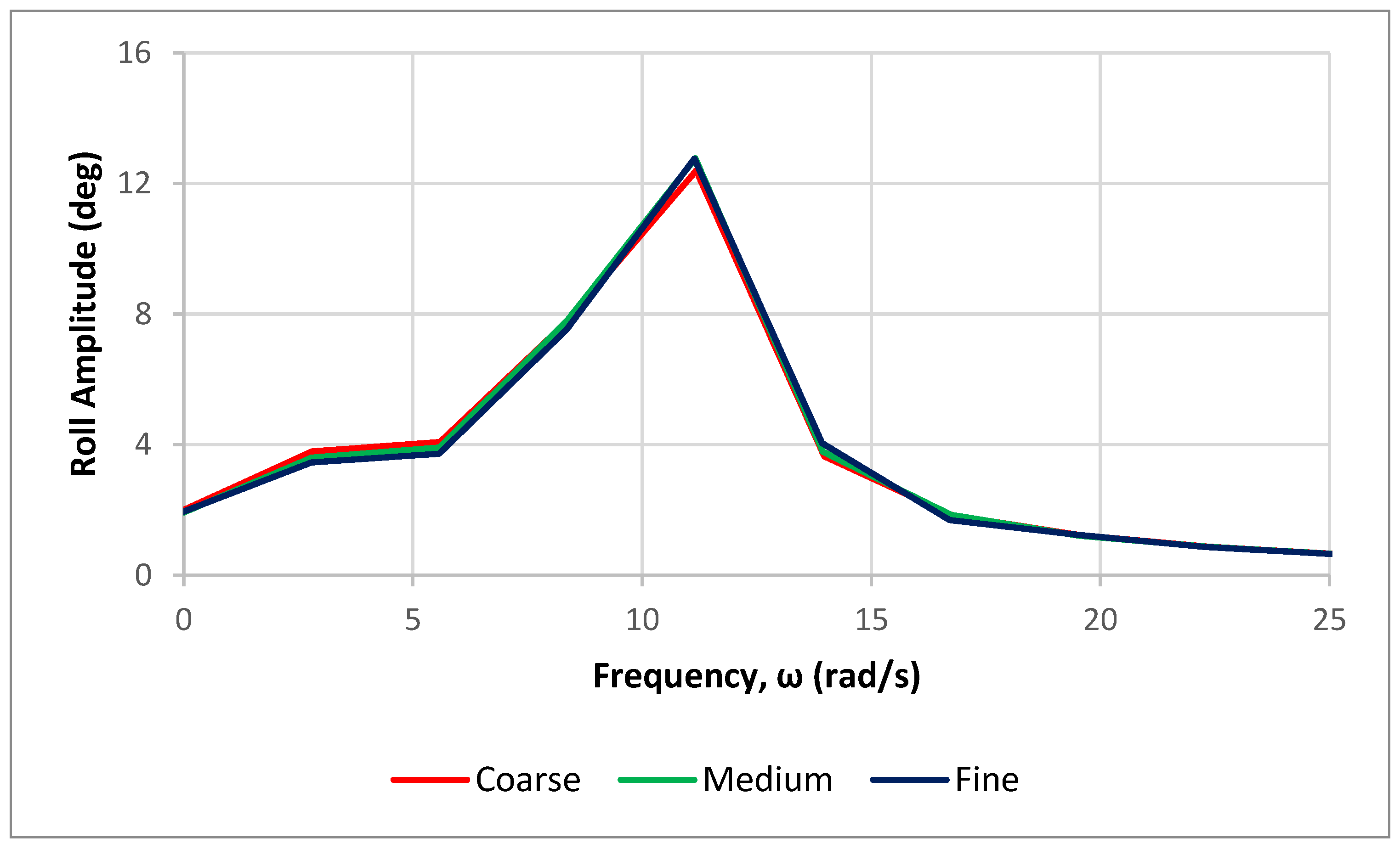
Fourier series (FS) analysis was used to quantify the results of roll decay simulation, which considered the unsteady time series of roll amplitude. This analysis converted the time-domain results into frequency-domain results. It was undertaken for the three mesh configurations, which were fine, medium and coarse. Next, the roll response in the frequency domain for different mesh configurations was compared. Each unsteady history φ(t) could be represented by a Fourier series in time, as shown in Equation (1).
φ t = φ 0 + n = 1 N φ n   . cos ω n t + γ n ,         n = 1 , 2 , 3 ,
where φ n is the nth harmonic amplitude and γn is the corresponding phase, which can be determined by the following equations.
φ n = a n 2 + b n 2
γ n = arctan b n a n
where
a n = 2 T   0 T φ t   . cos ω n t d t
b n = 2 T   0 T φ t   . sin ω n t d t
φ 0 = 1 T   0 T φ t d t
The 0th harmonic amplitude φ 0 is the average value of the time history of φ(t). Grid Convergence Index (GCI) analysis was used as a verification method. The formulae to calculate this index are shown in Equations (7)–(11). The verification study was carried out to quantify the numerical uncertainties of the CFD model. This index is based on Richardson extrapolation [19] and the method adopted according to Celik et al. [20].
S 1 , S 2 and S 3 are the frequency-domain roll responses obtained from the fine, medium and coarse configurations. R is the convergence ratio, which is monotonic for 0 < R < 1, oscillatory convergence for −1 < R < 0 and a divergent solution for R   < 1 or R   > 1. p is the order of accuracy. r is the refinement ratio.
ε 21 = S 2 S 1
ε 32 = S 3 S 2
R = ε 21 ε 32
p = 1 ln r 21 ln ε 32 ε 21 + q p where q p = ln r 21 p s / r 32 p s ,   and   s = sgn ε 32 / ε 21
G C I = 1.25 S 1 S 2 S 1 / r 21 p 1

3. Results

3.1. Experimental Study of Anti-Capsize Ship

The upright moment in the ship is an important aspect of ship stability because, when no moment exists, the ship will capsize. In this study, the self-righting moment was investigated to design a ship with the capability of avoiding capsizing; as a result, the moment of ship stability was positive in all conditions. This condition can be achieved with an extremely low center of gravity, and another assumption is that the ship is watertight during the rolling condition.
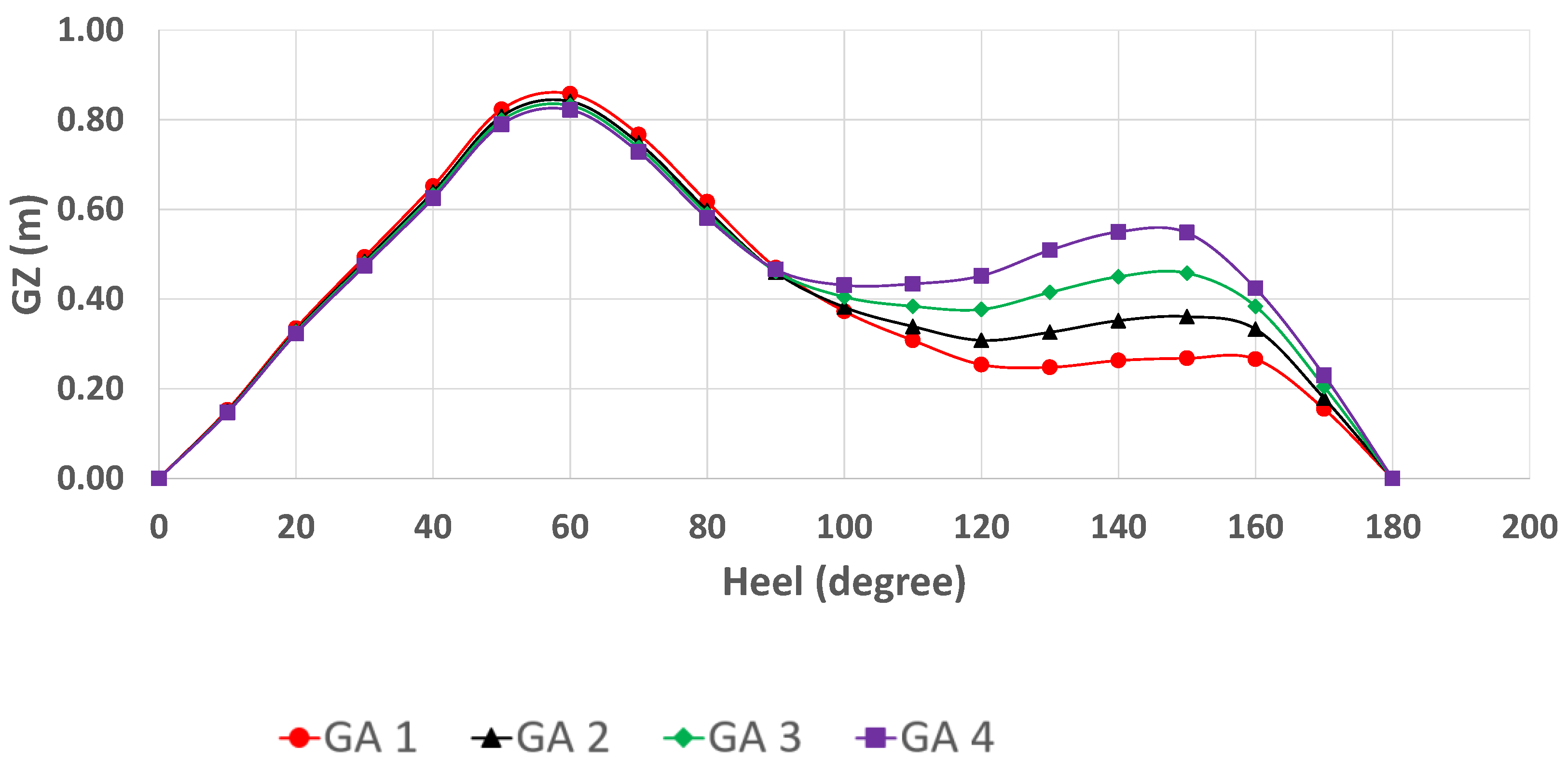
The calculation of the lever moment was conducted using strip theory; the ship was divided into sectional areas, and integration was performed using the Simpson methods. Figure 7 illustrates the lever moment of a ship in the light ship condition; in this situation, the ship only carries out the weight of the hull, without any passengers or accommodation. Red, black, green and purple indicate the first general arrangement (GA 1), second GA (GA 2), third GA (GA 3) and fourth GA (GA 4), respectively.
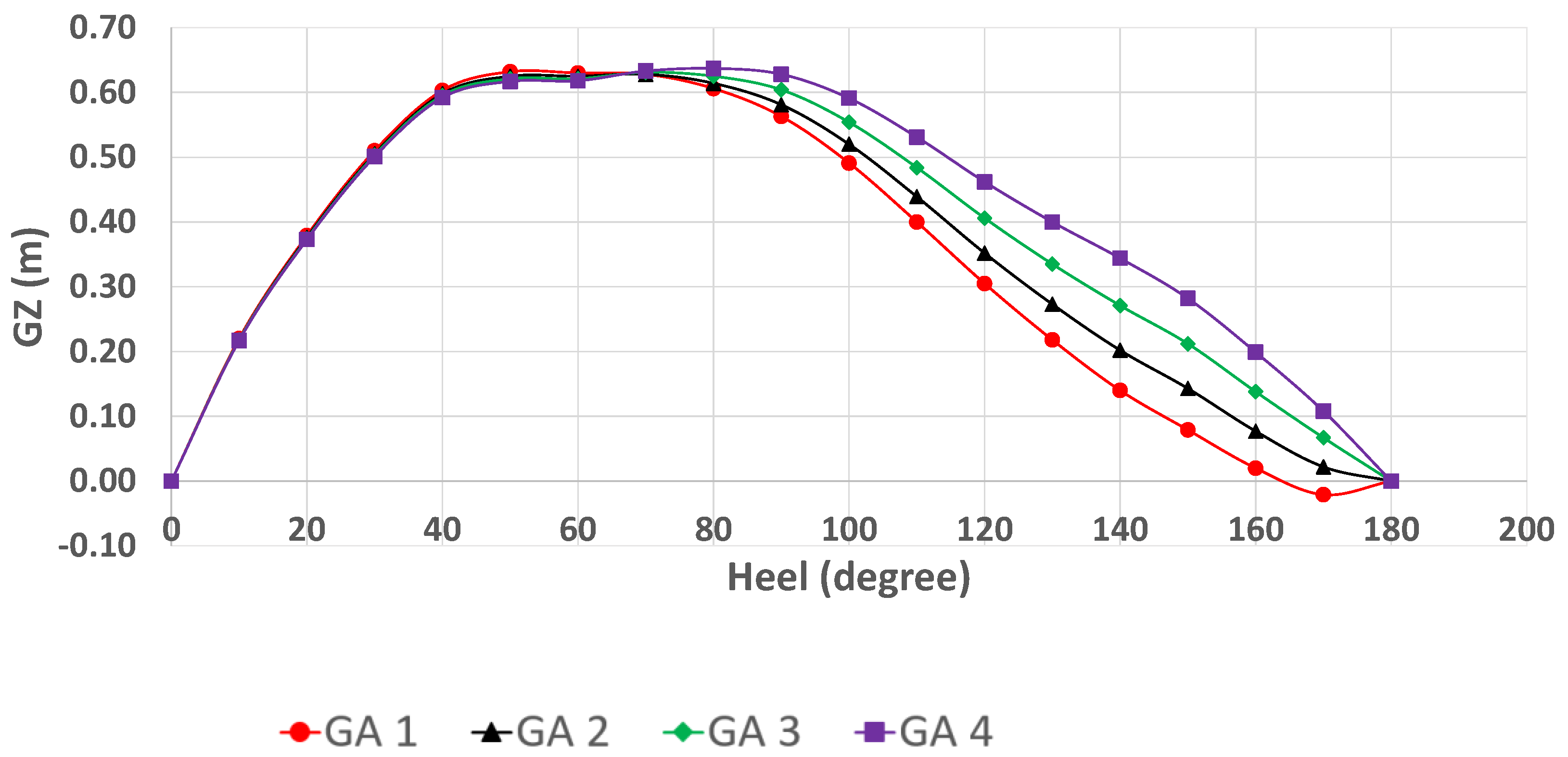
Figure 7 indicates that the ship has a positive moment from 10° to 170° for all GAs. The boat has a zero moment when it is in the 0° and 180° conditions. GA 4 has the highest lever moment after 100°; this situation is caused by the ship metacenter being higher compared to other deckhouse designs. The influence of the deckhouse causes the metacenter to become higher as the resulting lever moment becomes larger than before.
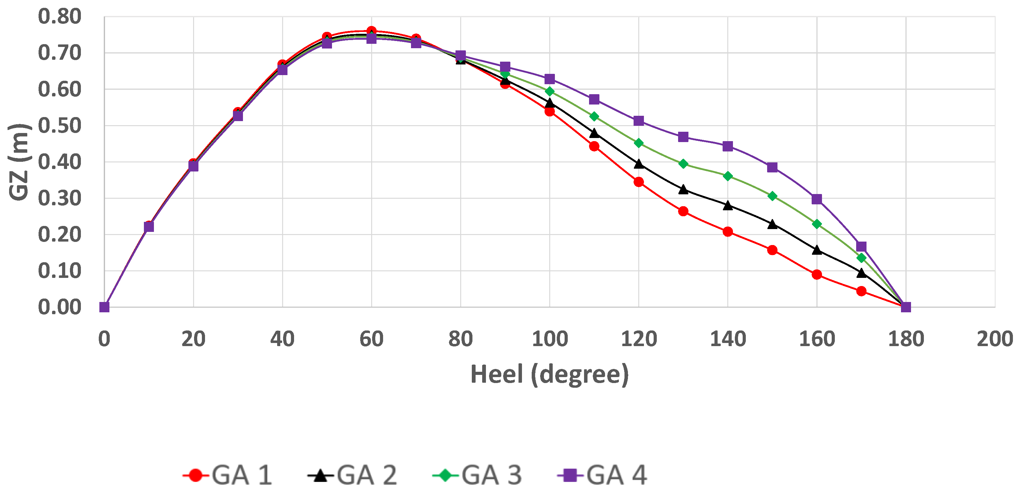
Figure 8 illustrates the lever moment for load cases without baggage, which is a similar phenomenon as shown in Figure 7. All ship designs have a positive moment in all rolling conditions. In this situation, there is the addition of mass from the crew and baggage; as a result, the center of gravity becomes larger compared to the first load condition. However, the ship still has a positive moment in all rolling conditions.
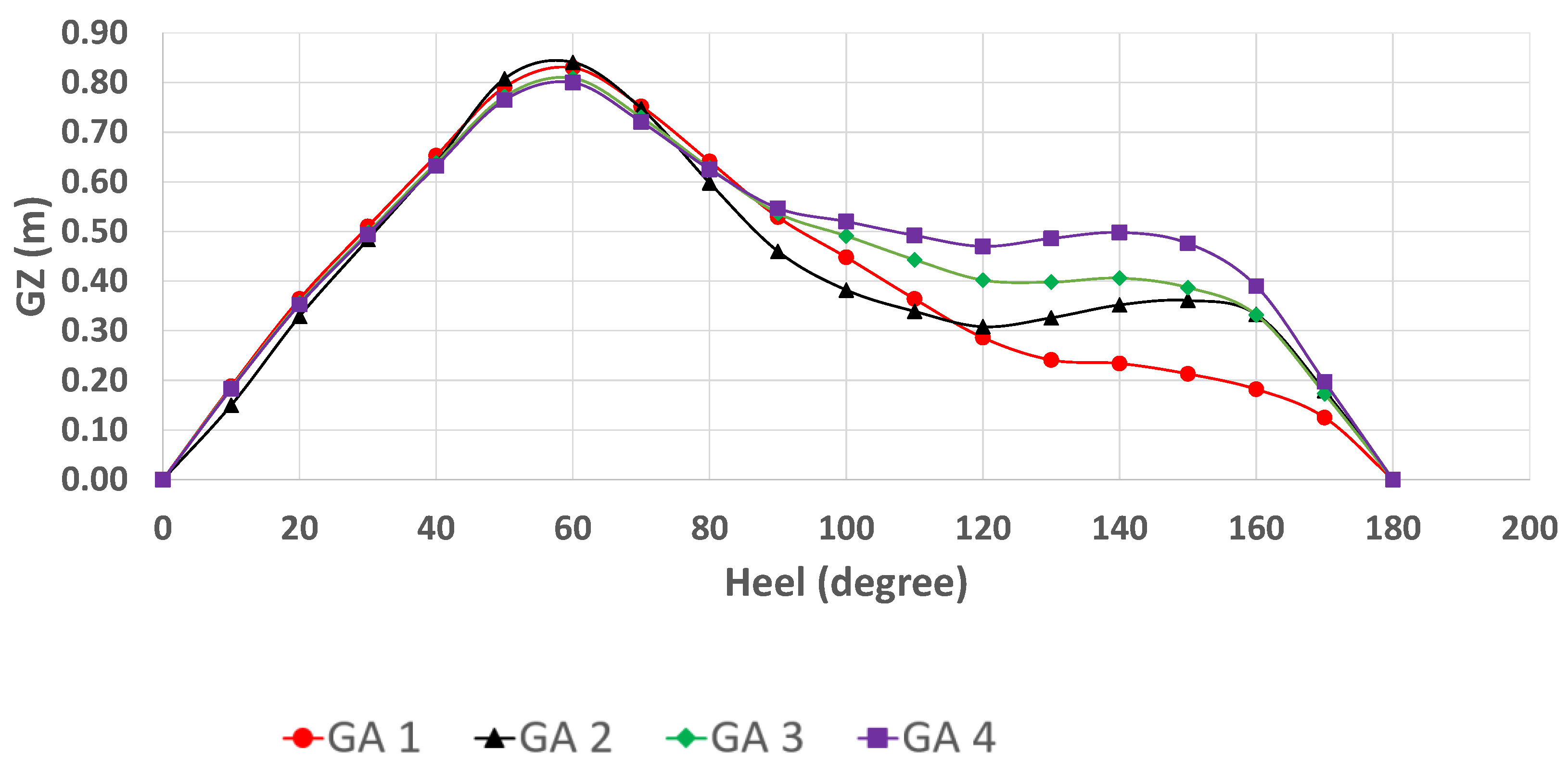
The next loading condition ship was set with a scenario of 50% cargo (see Table 2). It can be seen in Figure 9 that the positive moment still exists in all designed ships, without any negative moment in the study of the lever moment. However, in the full load condition, the result indicates that the ship design with the lowest deckhouse fails to return to an upright condition when rolling 170° (see Figure 10).
Figure 10 indicates the full load condition for the lever moment, and only the first design with the lowest deckhouse has a negative moment. The addition of mass creates a lower center of the metacenter and a larger center of gravity. Therefore, the lowest deckhouse fails as the center of gravity passes the center of the metacenter. On the contrary, the other three ship designs show positive moments, and the ship could return to the upright condition after rolling from a high roll angle.
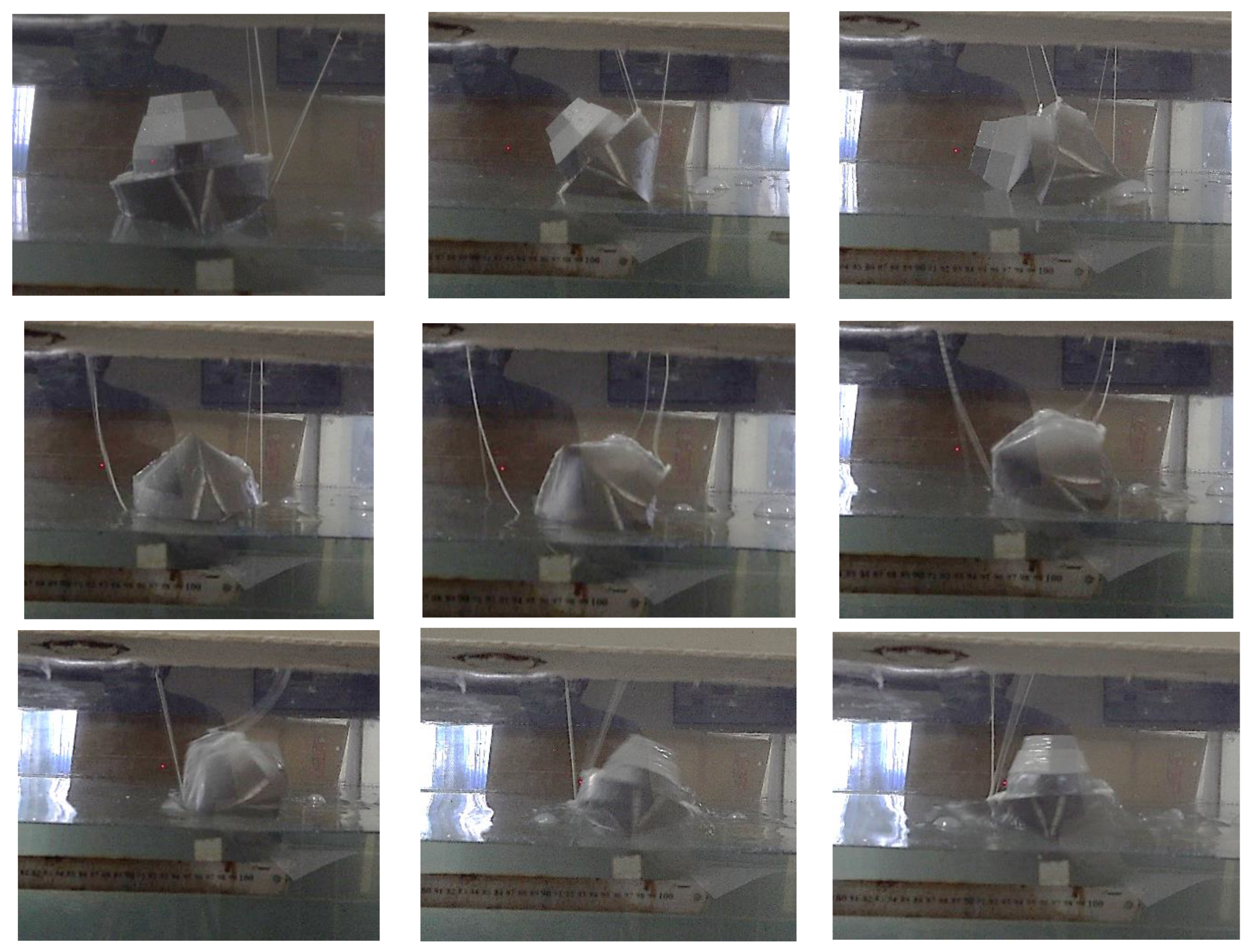
Verification was achieved with a physical model with 1:27.4 to prove that the ship has a positive moment in all conditions. In this study, only GA 4 was modeled in the laboratory to prove that our design has a positive moment in all rolling conditions. Figure 11 illustrates the self-righting capsize test in the towing tank. A rope was used to roll the ship to 180°; then, if there was a positive moment, as a result, the ship could return to an upright condition.
From Figure 11, the boat could return to an upright condition, and it is confirmed in Figure 10 that the ship has a positive moment in all rolling conditions. This physical model was tested in the full load condition. The lever moment is the lowest compared to other scenarios (see Figure 7, Figure 8, Figure 9 and Figure 10).

3.2. Numerical Computation of Anti-Capsize Ship with CFD

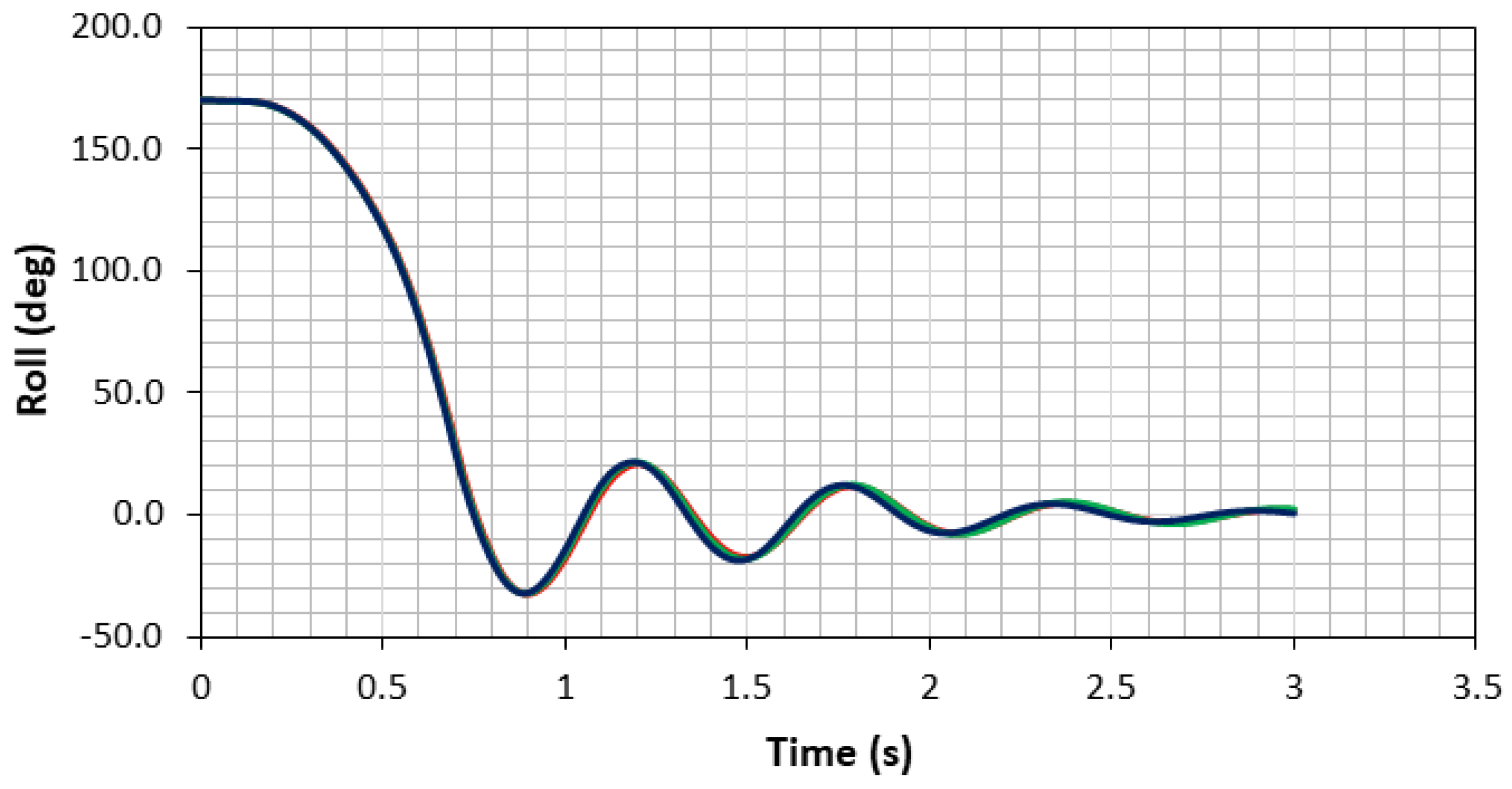
In this section, CFD simulation is described to demonstrate the positive moment of the general arrangement (GA) 4 model under a full load (load case 4). Grid Convergence Index (GCI) analysis was carried out to verify that the CFD calculation had the minimum error. Figure 12 shows the CFD result of the roll amplitude in the time domain for coarse, medium and fine mesh configurations.
The roll amplitude of the roll decay simulations for the fine, medium and coarse mesh configurations is shown in Figure 12. The initial roll condition was set as 170° to evaluate whether the boat could return to an upright condition (0°). Based on the simulation, the boat was successfully returned to an upright condition.
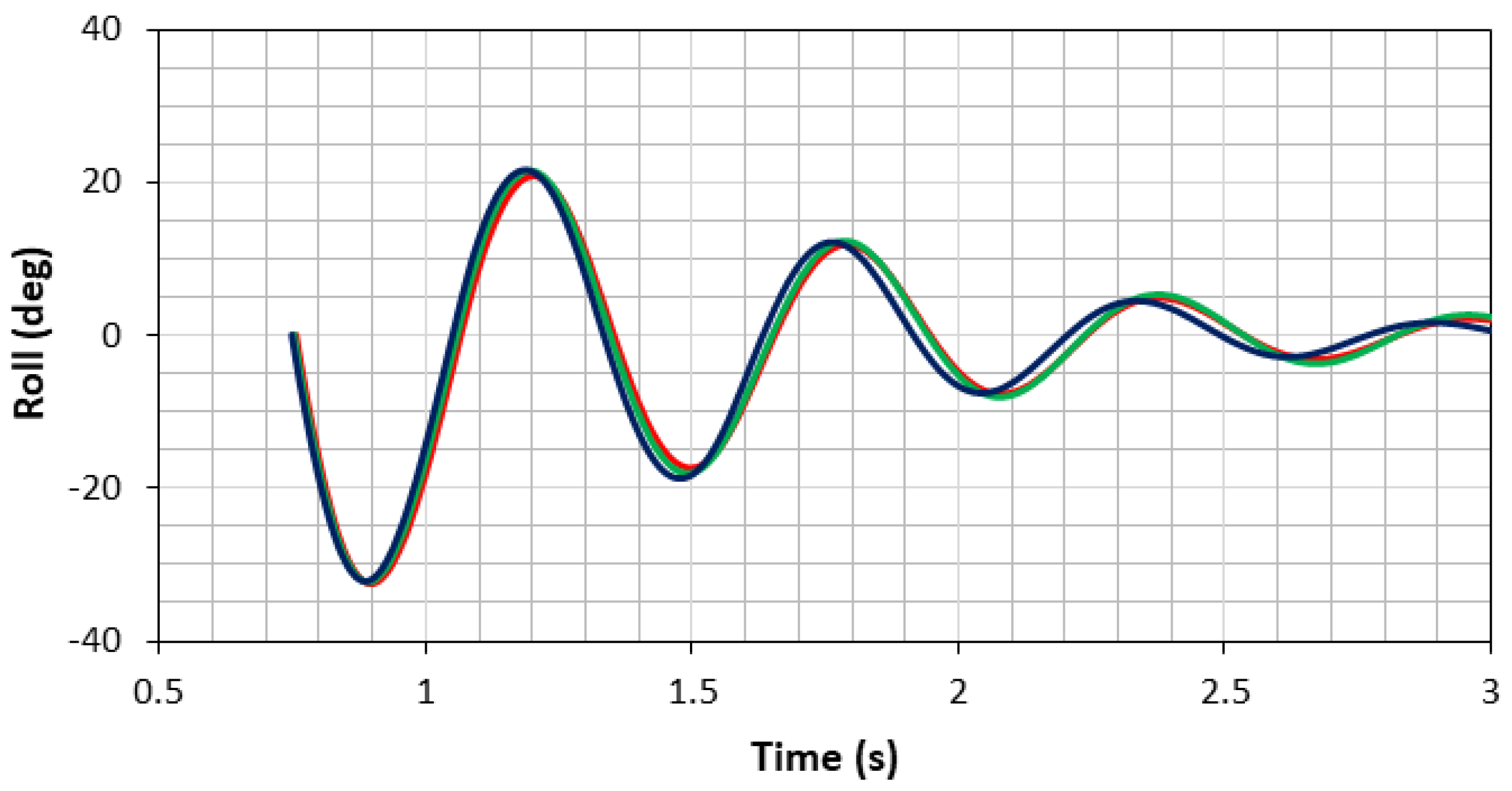
To quantify the time series of roll amplitude, Fourier series (FS) analysis was used. As mentioned in the Methodology, this method converts the time domain into the frequency domain. However, the roll amplitude in Figure 12 is plotted from the initial condition, which is 170°. There is a large difference from the initial condition (170°) to the first trough (around 30°). This may lead to an error in the FS analysis. Based on this reason, the roll amplitude that was used for FS analysis was taken from 0.75 s, with a roll amplitude of 0°. Figure 13 shows the time series of roll amplitude for FS analysis.
Figure 14 and Table 6 describe the results of the FS analysis. Figure 14 illustrates the roll amplitude from the roll decay CFD simulation in the frequency domain for the coarse, medium and fine mesh configurations. The peak of the curve is a roll amplitude occurring at a natural roll frequency. Table 6 explains the value of roll amplitude at the peak of the curve in Figure 14. These amplitudes are then used as S 1 ,   S 2 and S 3 in Grid Convergence Index (GCI) calculation, as shown in Equations (7)–(11).
Table 7 presents the results of CGI calculation. The table indicates the total mesh for each configuration and also the refinement ratio for the mesh configuration, which is 2 . Based on the roll amplitude obtained from FS analysis for fine, medium and coarse mesh configurations ( S 1 ,   S 2 and S 3 ), the GCI can be calculated using Equations (7)–(11). The GCI result is quite low, at 0.0041%, indicating that the numerical error in this CFD simulation is also small; thus, this CFD simulation is verified.
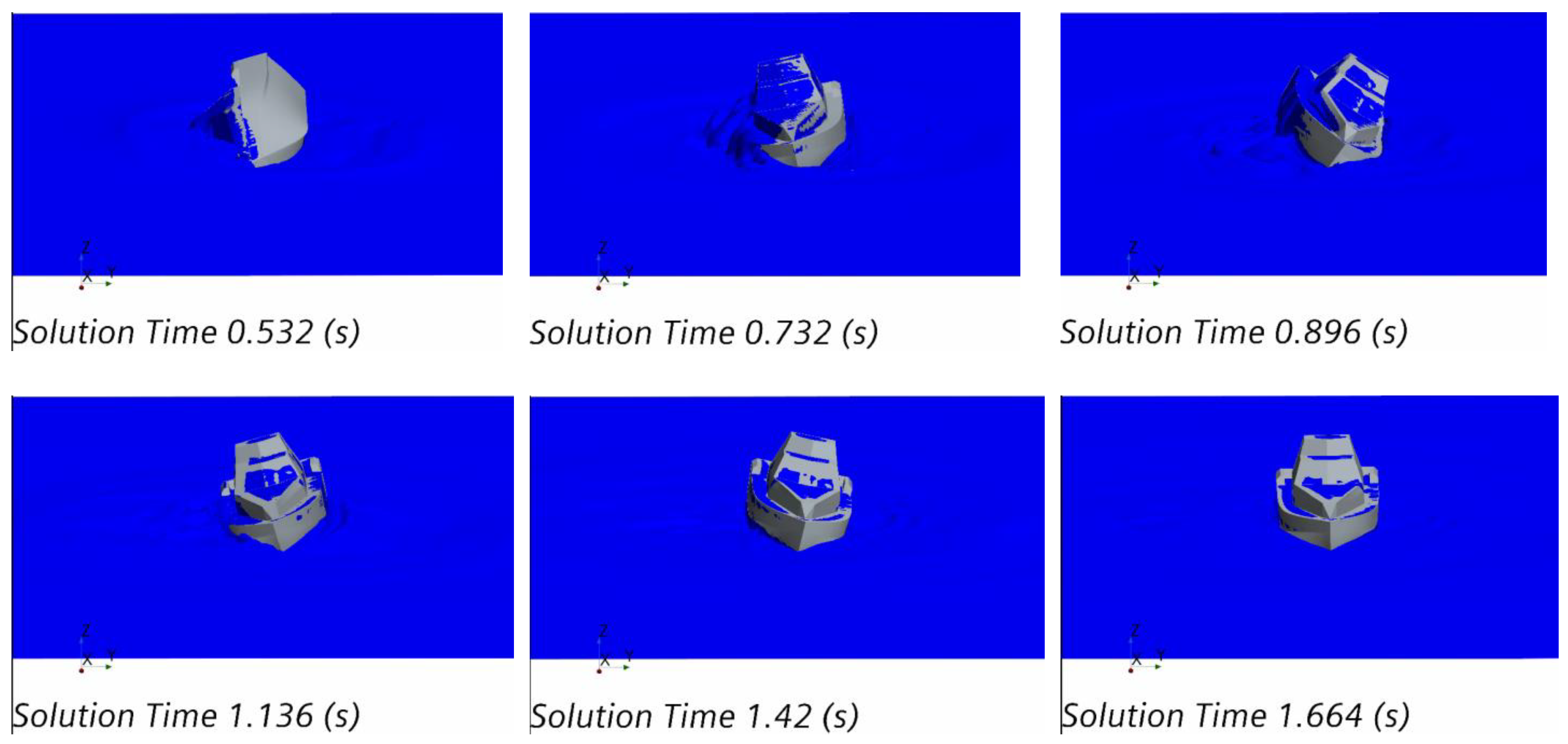
Figure 15 illustrates the CFD simulation in the full load condition for roll decay in a 3D view. It shows the same phenomenon as Figure 11, in which the positive moment exists when the boat has a roll angle of 170°. As the simulation used the scale model, the time needed by the boat to return to its original position was relatively quick. It can be seen in Figure 12 and Figure 14 that, at around 0.7 s, the boat has returned to an upright position. Based on the simulation, it is proven that the boat has a positive roll moment and is able to reach a stable position even from a heeling position of 170°. It should be noted that, in this simulation, the boat was considered watertight.
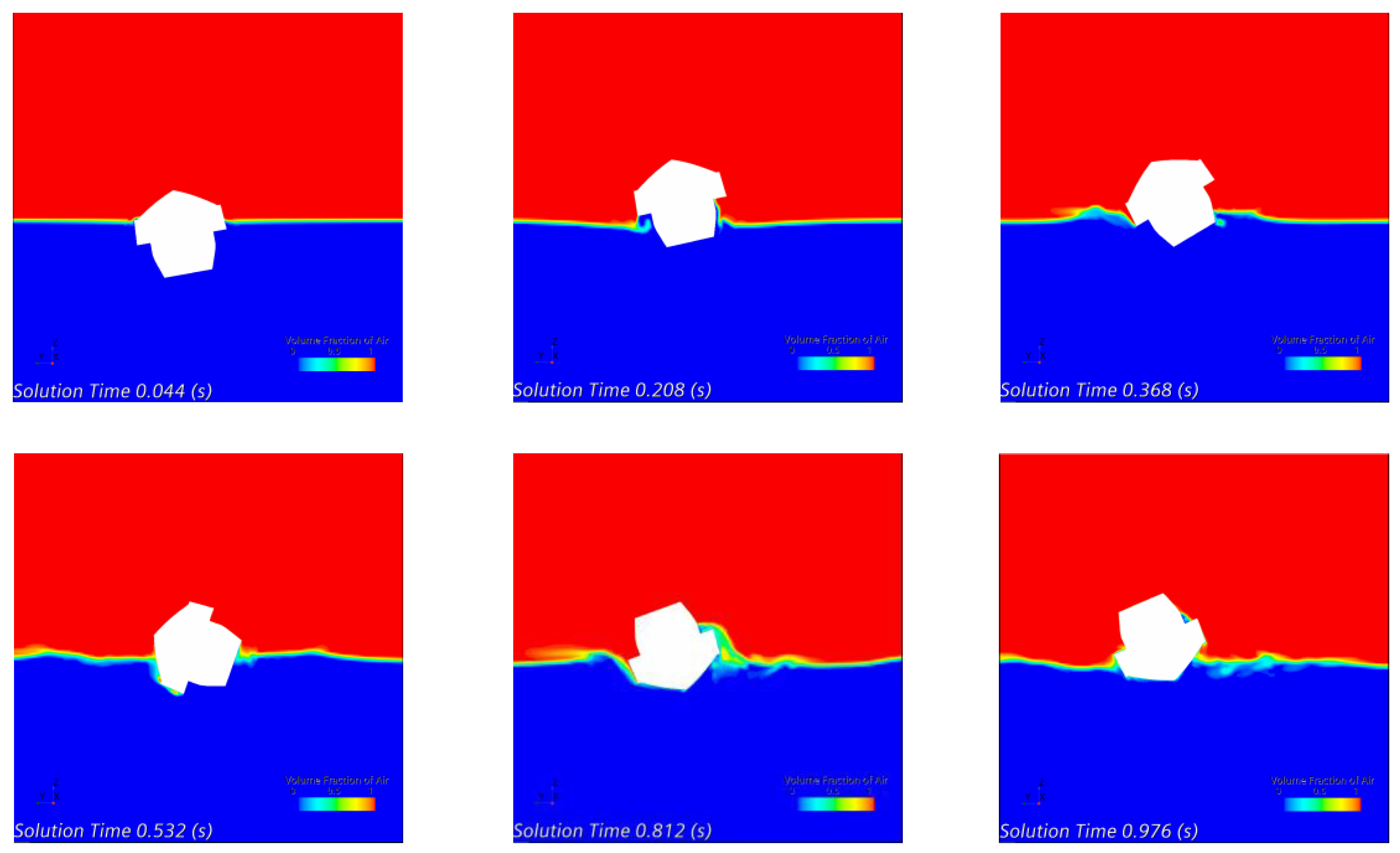
This CFD simulation used two phases, which were air and water. To capture the free surface between both phases, the Volume of Fluid (VoF) method was used. Figure 16 illustrates the result of the volume fraction of air with a color scale from blue to red, or from 0 to 1, in 2D view. The red color indicates that the volume fraction of air is 1, which is the phase that contains the air. When the volume fraction of air is zero, the phase does not contain the air phase. This means that the phase contains water (blue color). The free surface, which is located between the two phases, has a volume fraction of air of 0.5.
From this study, it was clearly shown that the height of the deckhouse has an important impact in improving the height of the ship’s metacenter. It can provide additional buoyancy when the boat has a high heeling angle, such as 170°. When the ship heels to the right, the center of buoyancy moves downward and the center of gravity moves upwards; then, the center of buoyancy twists with the center of gravity, and the ship starts to return to an upright condition, as shown in Figure 16. This shows that the center of gravity must be very low as the center buoyancy starts to move and twist and gives a positive moment. The opposite occurs when the center of gravity is high: the center of gravity moves upwards, and the center of buoyancy starts to move downwards, and then it will begin to enter a new equilibrium condition with the center of gravity at the top and the center of buoyancy in the downward position, which causes the ship to capsize due to the negative moment.
There have been few studies carried out for similar purposes and conducted on ship designs with anti-roll conditions without an additional device, and most studies have been conducted on ships capsizing due to waves, such as Liu et al. [21], who carried out a study on the interaction between the pure loss of stability, surf-riding and broaching. The pure loss of stability and surf-riding modes may cause broaching, indicating a similarly occurring condition and strong relation between these stability failure modes. Lin et al. [22,23] studied an anti-rolling device called Magnus anti-rolling, which employs swinging rotating cylinders based on the Magnus effect and can provide anti-rolling measures at any ship speed. Deng et al. [24] studied the effect of a bilge keel on ship stability using CFD. Many anti-roll devices have been developed to reduce ship roll in a wave; details can be found in [25].

4. Conclusions

A study of an anti-capsize ship design was conducted with a physical model and numerical approach. Four different heights of deckhouse were selected to improve the center of the metacenter. The height of the deckhouse improves the center of the metacenter and creates a positive roll moment. This research shows that the design of this ship has the capability of anti-capsizing due to the positive roll moment. The center of gravity and buoyancy are important parameters to obtain a self-righting moment in the heel condition. The center of gravity has to be in a very low position compared with an ordinary ship, so a self-righting moment exists during ship heeling in the roll condition. Three proven models have the capability of obtaining a self-righting moment, which was verified with one physical model and a numerical approach. In addition, the numerical approach showed the same phenomenon as strip theory and the physical model, whereby the ship has a self-righting moment at a heel angle up to 180°. Future works considering the parametric study of ship dimensions need to be carried out to complement the present study.

Author Contributions

Conceptualization, A.T. and A.F.Z.; methodology, A.T., M.A.F. and M.I.; software, M.A.F. and M.I.; validation, M.A.F. and A.T.; formal analysis, A.T., M.A.F. and O.M.; investigation, A.T., M.A.F. and M.I.; data curation, M.A.F., A.T. and M.I.; writing—original draft preparation, A.T., O.M., M.I. and A.F.Z.; writing—review and editing, A.T., O.M., M.I. and A.F.Z.; visualization, M.A.F., A.T. and M.I.; supervision, A.T. and A.F.Z.; project administration, A.T.; funding acquisition, A.T. All authors have read and agreed to the published version of the manuscript.

Funding

This research was funded by the Institute for Research and Community Services, Universitas Diponegoro (LPPM UNDIP), under a scheme international publication grant (RPI), grant number 569-169/UN7.D2/PP/VII/2022.

Data Availability Statement

Not applicable.

Acknowledgments

The authors are grateful to Adhitya Bayu Nugroho for the help during the construction of the ship model using the 3D printer.

Conflicts of Interest

The authors declare no conflict of interest. The funders had no role in the design of the study; in the collection, analyses or interpretation of data; in the writing of the manuscript; or in the decision to publish the results.

Nomenclature

LppLength between perpendicularsGZRighting lever
LoALength overalltTime
BShip breadth φ t Fourier series in time
HShip heightGCIGrid Convergence Index
TShip draftSRoll response
LCGLongitudional center of gravityRConvergence ratio
CGCenter of gravity p Order of accuracy
MCenter of metacenter r Refinement ratio

References

  1. Samuel; Trimulyono, A.; Manik, P.; Chrismianto, D. A Numerical Study of Spray Strips Analysis on Fridsma Hull Form. Fluids 2021, 6, 420. [Google Scholar] [CrossRef]
  2. Islam, H.; Sutulo, S.; Guedes Soares, C. Aerodynamic Load Prediction on a Patrol Vessel Using Computational Fluid Dynamics. J. Mar. Sci. Eng. 2022, 10, 935. [Google Scholar] [CrossRef]
  3. Liwång, H. Survivability of an Ocean Patrol Vessel—Analysis Approach and Uncertainty Treatment. Mar. Struct. 2015, 43, 1–21. [Google Scholar] [CrossRef] [Green Version]
  4. Maimun, A.; Priyanto, A.; Wong, K.S.; Pauzi, M.; Rafiqul, M. Effects of Side Keels on Patrol Vessel Safety in Astern Waves. Ocean Eng. 2009, 36, 277–284. [Google Scholar] [CrossRef]
  5. Windyandari, A.; Wahyudi, D. Methodology of The Hybrid Propulsion System (DMP & DEP) For Trimaran Type Fast Patrol Boat. Kapal J. Ilmu Pengetah. Teknol. Kelaut. 2011, 8, 161–172. [Google Scholar]
  6. Amiadji, A.; Baidowi, A.; Arief, I.S.; Ricinzky, F.P. CFD Based Analysis of Resistance and Pitch Motion of Novel Flat Plate Panel Hull Vessel. Kapal J. Ilmu Pengetah. Teknol. Kelaut. 2022, 19, 9–22. [Google Scholar] [CrossRef]
  7. Putra, A.B.C.; Hasanudin, H. Desain Self-Righting Rescue Boat Untuk BASARNAS. J. Tek. ITS 2019, 8, G99–G105. [Google Scholar] [CrossRef]
  8. Trimulyono, A.; Zakki, A.F.; Fuadi, M.A. Experimental Study of a Ship with the Self-Righting Moment in Extreme Condition. IOP Conf. Ser. Earth Environ. Sci. 2022, 1081, 012006. [Google Scholar] [CrossRef]
  9. Liu, L.; Chen, M.; Wang, X.; Zhang, Z.; Yu, J.; Feng, D. CFD Prediction of Full-Scale Ship Parametric Roll in Head Wave. Ocean Eng. 2021, 233, 109180. [Google Scholar] [CrossRef]
  10. Xu, S.; Gao, Z.; Xue, W. CFD Database Method for Roll Response of Damaged Ship during Quasi-Steady Flooding in Beam Waves. Appl. Ocean Res. 2022, 126, 103282. [Google Scholar] [CrossRef]
  11. Castro, A.M.; Carrica, P.M.; Stern, F. Full Scale Self-Propulsion Computations Using Discretized Propeller for the KRISO Container Ship KCS. Comput. Fluids 2011, 51, 35–47. [Google Scholar] [CrossRef]
  12. Jasak, H.; Vukčević, V.; Gatin, I.; Lalović, I. CFD Validation and Grid Sensitivity Studies of Full Scale Ship Self Propulsion. Int. J. Nav. Archit. Ocean Eng. 2019, 11, 33–43. [Google Scholar] [CrossRef]
  13. Shen, Z.; Wan, D.; Carrica, P.M. Dynamic Overset Grids in OpenFOAM with Application to KCS Self-Propulsion and Maneuvering. Ocean Eng. 2015, 108, 287–306. [Google Scholar] [CrossRef]
  14. Pereira, F.S.; Eça, L.; Vaz, G. Verification and Validation Exercises for the Flow around the KVLCC2 Tanker at Model and Full-Scale Reynolds Numbers. Ocean Eng. 2017, 129, 133–148. [Google Scholar] [CrossRef]
  15. Lungu, A. Numerical Investigation of the 6-DOF Seakeeping Performances of the KCS Containership. J. Mar. Sci. Eng. 2022, 10, 1397. [Google Scholar] [CrossRef]
  16. Sun, H.-B.; Yang, S.-Q.; Xu, Y.-F.; Xiao, J.-F. Prediction of the Pitch and Heave Motions in Regular Waves of the DTMB 5415 Ship Using CFD and MMG. J. Mar. Sci. Eng. 2022, 10, 1358. [Google Scholar] [CrossRef]
  17. Menter, F.R. Two-Equation Eddy-Viscosity Turbulence Models for Engineering Applications. AIAA J. 1994, 32, 1598–1605. [Google Scholar] [CrossRef] [Green Version]
  18. Hirt, C.W.; Nichols, B.D. Volume of Fluid (VOF) Method for the Dynamics of Free Boundaries. J. Comput. Phys. 1981, 39, 201–225. [Google Scholar] [CrossRef]
  19. Richardson, L.F. The Approximate Arithmetical Solution by Finite Differences of Physical Problems Involving Differential Equations, with an Application to the Stresses in a Masonry Dam. Philos. Trans. R. Soc. Lond. Ser. A Contain. Pap. Math. Phys. Character 1910, 210, 307–357. [Google Scholar]
  20. Celik, I.; Ghia, U.; Roache, P.; Freitas, C.; Coloman, H.; Raad, P. Procedure for Estimation and Reporting of Uncertainty Due to Discretization in CFD Applications. J. Fluids Eng. 2008, 130, 078001. [Google Scholar] [CrossRef] [Green Version]
  21. Liu, L.; Yao, C.; Feng, D.; Wang, X.; Yu, J.; Chen, M. Numerical study of the interaction between the pure loss of stability, surf-riding, and broaching on ship capsizing. Ocean Eng. 2022, 266, 112868. [Google Scholar] [CrossRef]
  22. Lin, J.; Han, Y.; Su, Y.; Wang, Y.; Zhang, Z.; Jiang, R. Hydrodynamic performance of a Magnus anti-rolling device at zero and low ship speeds. Ocean Eng. 2021, 229, 109008. [Google Scholar] [CrossRef]
  23. Lin, J.; Guo, C.; Zao, D.; Han, Y.; Su, Y. Hydrodynamic simulation for evaluating Magnus anti-rolling devices with varying angles of attack. Ocean Eng. 2022, 260, 111949. [Google Scholar] [CrossRef]
  24. Deng, R.; Chen, S.; Luo, F.; Wang, Y.; Wu, T. Numerical study on viscous flow field of forced rolling of ships with bilge keels. Ocean Eng. 2021, 239, 109860. [Google Scholar] [CrossRef]
  25. Barrass, C.B.; Derrett, D.R. Ship Stability for Masters and Mates, 6th ed.; Elsiever: Amsterdam, The Netherlands, 2006; pp. 366–368. [Google Scholar]
Figure 1. Design of line plan of patrol vessel and SAR.
Jmse 11 00133 g001
Figure 2. General arrangement of patrol vessel with 6 passengers.
Jmse 11 00133 g002
Figure 3. Variations in deck house height: 2.01 m (a), 2.11 m (b), 2.21 m (c) and 2.31 m (d).
Jmse 11 00133 g003
Figure 4. Physical modeling of ship with scale 1:27.4 with the highest deckhouse (a), hull form model (b), solid ballast (c) and ship model (d).
Jmse 11 00133 g004
Figure 5. Computational domain for self-righting moment in CFD.
Jmse 11 00133 g005
Figure 6. Two regions and the refinements and fine mesh configuration.
Jmse 11 00133 g006
Figure 7. Righting lever for light ship condition.
Jmse 11 00133 g007
Figure 8. Righting lever for ship stability for load case 2.
Jmse 11 00133 g008
Figure 9. Righting lever for ship stability for load case 3.
Jmse 11 00133 g009
Figure 10. Righting lever for ship stability for load case 4.
Jmse 11 00133 g010
Figure 11. Physical model for self-righting moment at 180°.
Jmse 11 00133 g011
Figure 12. CFD result of roll amplitude from roll decay simulation.
Jmse 11 00133 g012
Figure 13. Roll amplitude that was used for Fourier series (FS) analysis.
Jmse 11 00133 g013
Figure 14. Roll amplitude in frequency domain obtained from Fourier series analysis.
Jmse 11 00133 g014
Figure 15. The results of CFD simulation of self-righting moment from 3D perspective.
Jmse 11 00133 g015aJmse 11 00133 g015b
Figure 16. Numerical simulation of two phases of CFD self-righting moment.
Jmse 11 00133 g016aJmse 11 00133 g016b
Table 1. Principal dimensions of ship.
Principal Dimension (Units in m)
Lpp13.0 m
B4.2 m
H2.19 m
T1.15 m
Table 2. Load case of ship condition for calculation of lever arm.
ItemLoad Case 1Load Case 2Load Case 3Load Case 4
Passenger0%100%100%100%
Passenger Baggage0%100%100%100%
Cargo0%0%50%100%
Diesel oil0%100%100%100%
Table 3. Principal particulars of model with scale 1:27.4.
Model ParticularDimension (cm)
LoA50
Lpp47.4
B15
T4.2
H8
Table 4. Calculation of the center of gravity and the total weight of the model.
Itemm (gr)F (N)LCG (cm)Moment LCG (N.cm)KG (cm)Moment KG (N.cm)
Hull377.003694.6019.3971,627.214.9218,184.82
Upper Deck159.001558.2022.1334,484.5211.5718,022.14
Load7267114.818.77133,523.45162.6318,726.1536
Total1262.005252.8019.38239,635.1864.4454,933.116
Table 5. Comparison of calculation of center of gravity.
ItemFull-Scale ShipScaled ShipDifference (%)
LCG20.6519.386.15%
KG4.894.449.20%
Table 6. Fourier series results.
No.Mesh Sizeωroll (rad/s)Troll (s)Roll Amplitude
1Fine11.160.563012.753°
2Medium11.180.562012.741°
3Coarse11.200.561012.369°
Table 7. Grid Convergence Index (GCI) results.
Total mesh fine configuration4,213,084
Total mesh medium configuration1,592,881
Total mesh coarse configuration709,885
Refinement ratio, r 2
Fine   configuration   solution   ( roll ) ,   S 1 12.753°
Medium   configuration   solution   ( roll ) ,   S 2 12.741°
Coarse   configuration   solution   ( roll ) ,   S 3 12.369°
Convergence ratio, R0.033
Convergence typeMonotonic (0 < R < 1)
Order of accuracy, p9.8394
GCI (%)0.0041%
Disclaimer/Publisher’s Note: The statements, opinions and data contained in all publications are solely those of the individual author(s) and contributor(s) and not of MDPI and/or the editor(s). MDPI and/or the editor(s) disclaim responsibility for any injury to people or property resulting from any ideas, methods, instructions or products referred to in the content.