1. Introduction
The International Renewable Energy Agency (IRENA) claims that wind power will provide more than 33% of global electricity demand by 2050 [
1]. Many countries are establishing very large offshore wind farms in a quest to meet their clean energy targets. The total installed wind energy capacity in Europe from Offshore Wind Turbines (OWT) has increased from 84 GW in 2010 to 189 GW in 2018 [
2]. In order to speed up the adoption and reduce the cost, there is a need to constantly improve the design of OWT foundations.
An OWT faces a combination of complex loads throughout life, and fatigue life is the main performance criterion of OWT foundations [
3]. The complexity and computationally expensive nature of time-series fatigue analysis force the researchers to make simplified assumptions, which impacts the accuracy of modern-day research. A complete wind resource analysis was done in [
4] to describe the method of reference site selection. The study also highlighted the method of correlating short-term data with multi-year historical data to extract the environmental data for any research. The environmental data, including the wind and wave resource information, is needed to perform any time-series fatigue simulation. The author discusses the preliminary design of monopile foundations to support larger wind turbines and deeper water in [
5]. A time-series wind field was generated in the TurbSim, but the study only focused on DLC (Design Load Case) 1.2 and ignored conditions above cut-off wind speed and wave currents.
The soil-structure interaction is a key player in offshore foundation modelling and is discussed in [
6]. The industry standard definition of pile-soil interaction is inaccurate for offshore foundations with a large diameter (monopile). The effect on the fatigue life of monopile foundations was studied using four soil foundation models in [
7], which resulted in the variation of fatigue damage up to 22% based on different soil models. The PISA project proposed a different soil-pile definition method based on field testing and numerical results [
8]. However, the method only shows good accuracy at the testing site and can not be used on other or multi-layered soils. A detailed FEA analysis was performed in [
9] based on five constraints (fatigue, stress, vibration, buckling, and deformation). It was observed that fatigue performance is the primary design driver of the jacket foundations. Abdulhakim et al. studied the structural reliability of the jacket subjected to corrosion fatigue [
10]. The spectral fatigue analysis method was used on an eight-legged oil and gas jacket foundation and showed that 73 joints had a service life of fewer than 20 years [
11]. The research was performed to study the effect of design parameters and foundation types (fixed base, monopile, and caisson) on the dynamic response and fatigue in [
12]. However, the fatigue analysis was performed in a MATLAB-based tool (MLife) and did not include the time series aspect. A study was performed to analyse modelling parameters’ effect on the jacket foundation’s dynamic response [
13], but the effect on fatigue life was not considered. The author also compared the dynamic response of monopile, jacket, and tripod foundation in [
14] without including the complex time-series fatigue phenomenon. The structural redundancy’s effect on fatigue life and life extension was studied in [
15]. The author proposes using the fracture mechanics approach along with the fatigue analysis in the future. Thanh-Tuan et al. presented a cost-effective three-legged jacket by studying various bracing patterns. The dynamic response was significantly changed with the change in the bracing pattern [
16]. The dynamic responses of monopile and jacket foundations were compared in [
17]. It was observed that the jacket foundation had a better dynamic response, and the monopile foundation was not suitable for the Korean offshore wind farm.
An integrated or super-element design approach can be used for time-series fatigue analysis. A previous study compared integrated and super-element approaches in [
18] and found similar fatigue damages. The same set of software was used to perform fatigue analysis of a 10-MW wind turbine using an integrated design approach in [
19]. It was observed that integrated or super-element approaches could be used alternatively. When combined with hydro-servo-elastic software (e.g., Bladed), the computational time can be significantly reduced, resulting in improved fatigue analysis accuracy due to the interaction of the whole model. The most used OWT foundations are monopile and jacket foundations. Monopiles are primarily used for shallow water with depths up to 30 m. The jacket foundations, on the other hand, can be successfully used for water depths above 40 m. Moreover, jacket foundations can be used in multi-layered soil, but monopiles are mostly used in sand and gravel soils. The primary objective of this research is to establish the effect of various parameters on the jacket foundation’s dynamic response and fatigue life. This study focuses on a super-element method, where an OC4 jacket foundation in a 50 m water depth, modelled in Sesam, is reduced to the super-element file. The super-element model provides information on the model’s mass matrix, gravity vector, and stiffness matrix. The super-element model includes the values of these parameters at the interface point (intersection of tower and TP). The interface point is then shared with the Bladed software to compute the time series of forces and moments in three axes. The time-series of loads are imported in the Sesam Wind Manager (SWM) to generate a time-series of stress range, eventually used to determine fatigue damages. The process is repeated on similar environmental conditions for a set of parameters and design modifications to obtain their effect on the dynamic response and fatigue damages. This paper contributes to knowledge with a unique set of changes in the design, material of transition piece, and grouted connection, and observes their effect on the dynamic response and fatigue life. The study also includes comprehensive details of the complex design of FLS analysis using the super-element method.
The paper is organised as follows.
Section 2 describes the reference model.
Section 3 explains the model validation methodology.
Section 4 explains the methodology used for FLS analysis.
Section 5 discusses the results, and
Section 6 concludes the study.
1.1. Sources of Loads
An offshore wind turbine faces a series of complex loads during its service life. The design standards DNV-OS-J101 [
20] and IEC 61400-3 [
21] suggest the list of loads to consider while performing analysis. The DNV-RP-C205 [
22] standard was used to calculate each environmental load. The loads faced by an offshore wind turbine are usually classified into the following groups.
1.1.1. Inertia Loads
The loads are encountered due to the mass of Rotor Nacelle Assembly (RNA), Transition Piece (TP), tower, and foundation. These loads contribute most to the buckling and significantly affect the modal analysis. The structure can fail if an OWT encounters resonance due to the poor design, emphasising the need to consider these loads during the design process.
1.1.2. Wind Loads
The wind loads caused by the drag change with the height and the mean wind speed. The power-law profile is used to examine wind speed variation with height using Equation (1).
where,
shows the wind speed at the hub height and
shows the roughness coefficient, usually 0.115 for offshore conditions. The wind loads as a function of height can be calculated by using Equation (2). Where
D(
z) represents the tapered diameter of the tower and
CD,T shows the drag coefficient of the tower at any height z.
1.1.3. Rotor’s Aerodynamic Loads
Due to airflow interaction, the combination of static and dynamic loads acting on the wind turbine rotor generates aerodynamic loads. The loads faced by the rotor are transferred to the top of the tower. The values of these loads for this study were obtained from [
23] to perform the modal analysis.
1.1.4. Current Loads
Like the wind loads, the current loads are height and drag-dependent. Morison’s equation describes the sub-surface current velocity by an exponential profile from MSL to the seabed. Where d is the water depth from MSL to the seabed and
Vc,MSL is the current velocity at MSL [
24].
1.1.5. Hydrostatic Load
The offshore foundation is immersed in seawater, which results in hydrostatic pressure. The hydrostatic load (
Fh) is a permanent normal load that increases with depth (
h) and can be calculated by Equation (4), where g is the gravitational constant.
1.1.6. Wave Loads
Morison’s equation is used because the wavelength, sea depth, shape, and size of an offshore jacket foundation are all governed by drag. The diameter
D of the jacket’s member must be smaller than one-fifth of the wavelength for Morison’s equation to be employed. The current and wave loads can be computed for the structure submerged in the water by using Morison’s equation [
25]. Where
Cm and
Cd are inertia and drag coefficients,
D is the member’s diameter,
Ux and
ax are velocity and acceleration induced by the current and wave.
4. Fatigue Limit State (FLS) Analysis
The fatigue design of OWT support structures is controlled by the dynamic response to combined aerodynamic and hydrodynamic loads [
34]. The S-N curve and fracture mechanics approaches are the two most often used fatigue assessment techniques. As advocated by the standards [
35,
36], the S-N curve method is the focus of this research. The S-N curve, which is based on experimental data and is a plot of Stress S against the number of cycles N, is used to calculate the fatigue failure of an object. The experiments are repeated for many similar specimens under stress to obtain the design S-N curve. The stress range at a point is related to the number of cycles to failures with the help of Equation (6). Where
N is the number of cycles to failure,
m is the negative inverse slope of the S-N curve,
σ is the stress, and
C is the intercept of the S-N curve with the log of the number of cycles
N. This analysis involves estimating stress concentration factors (SCFs) for tubular joints based on geometry and butt welds. The fatigue life is based on the rainflow counting of stress time histories [
37].
4.1. Methodological Approach for FLS
The FLS analysis is performed based on the super-element approach, which is discussed later. The FLS load calculation is based on the Design Load Cases (DLCs) recommended by [
36]. FLS analyses are typically performed for DLC 1.2, DLC 6.4, and DLC 7.2. This study focuses on the DLCs given in
Table 7, and DLC 7.2 (idling after fault) is omitted because most of the fatigue life is based on these DLCs only. Moreover, a reduced form of scatter diagram in the North-sea (in
Table 8) is used to obtain the result due to the increased number of simulations to observe the effect of different parameters on the time-series fatigue life.
The validated foundation model in
Section 4.1 was exported to the SWM, where the Wajac input file defined the hydrodynamic properties, and Sestra defined the type of analysis. The super-element files were generated based on the input data.
4.1.1. Super-Element Design Method
Sesam offers time-series FLS analysis in integrated and super-element approaches. The entire structure (including the tower) is modelled in Genie and exported to Bladed (version 4.12) to generate time-series loads in an integrated design approach. The study [
38] uses an integrated design approach on a 10-MW offshore wind turbine. However, in the super-element approach, only the jacket and the wave loads are exported to Bladed in the form of a super-element.
The super-element method is implemented in this research because it is extensively used in the industry due to the lack of a requirement to share the jacket design and the ability to export complex designs [
39]. The super-element model should behave similarly to the integrated model. DNV has published verification studies showing the accuracy of the super-element method in [
40]. Moreover, integrated and super-element approaches are compared in [
18].
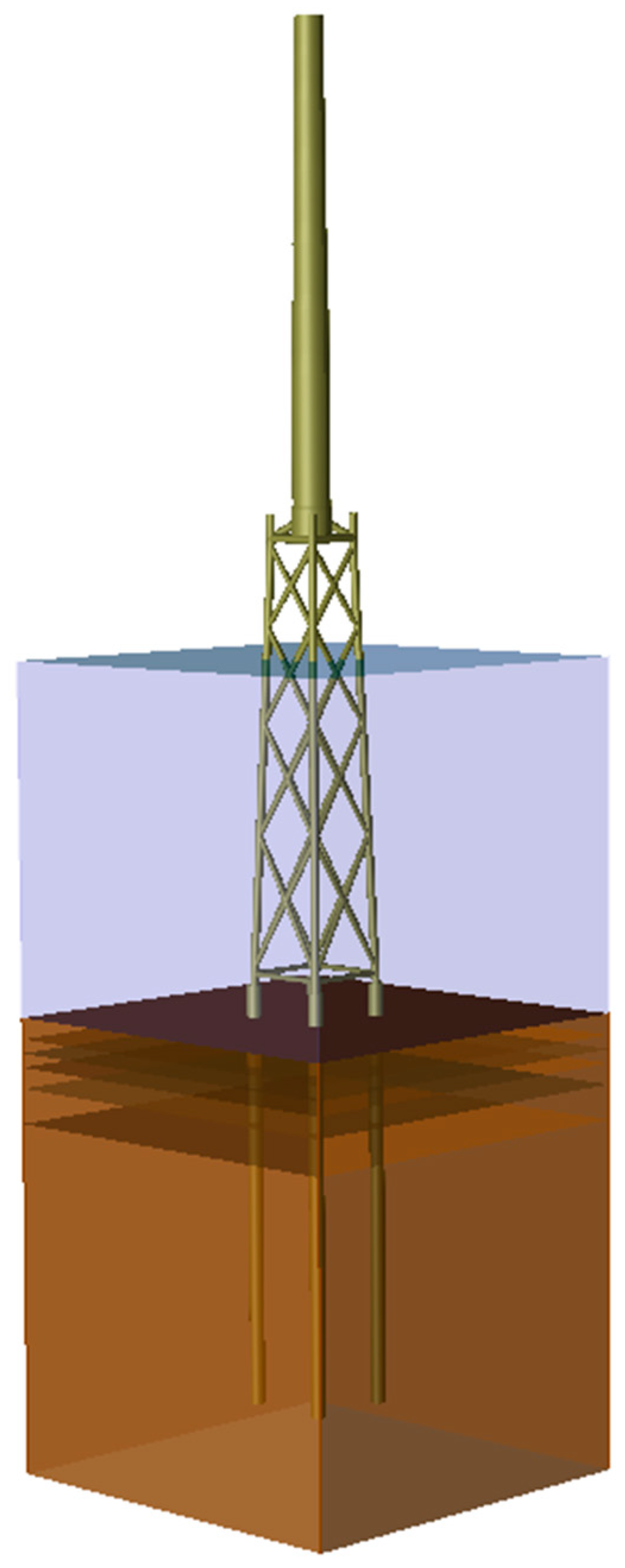
Figure 6 shows the schematic of the super-element method.
The super-element files contain the model’s mass matrix, gravity vector, and stiffness matrix information. The damping matrix was generated based on the Rayleigh coefficients, stiffness, and mass matrices. The original model was verified with the literature, as discussed in
Section 3. However, the super-element data must also be converged (spectral and spatial) to replace the original model.
Spectral Convergence
The boundary node is at the interface point and contains only six degrees of freedom (DOFs) which is not enough. The number of DOFs is increased until there is an agreement between the dynamic response of the original model and the super-element model. The number of modes was selected after the dynamic response converged and was similar to the modal shapes based on the standalone jacket model in Genie. Hence, 40 additional DOFs were added to the super-element model to capture actual dynamic responses based on the original model. The verification report suggests that using 40 or more modes may reduce the difference between the two models to a maximum of 0.5%. Genie is used to obtain the eigenvalue frequencies of the jacket (excluding RNA and tower), and SWM obtains the super-element model’s frequencies. The model’s modal frequencies are compared for the first 20 modes in
Table 9 and show a maximum difference of only 0.16%. It shows that both models can be used interchangeably to produce similar responses.
Spatial Convergence
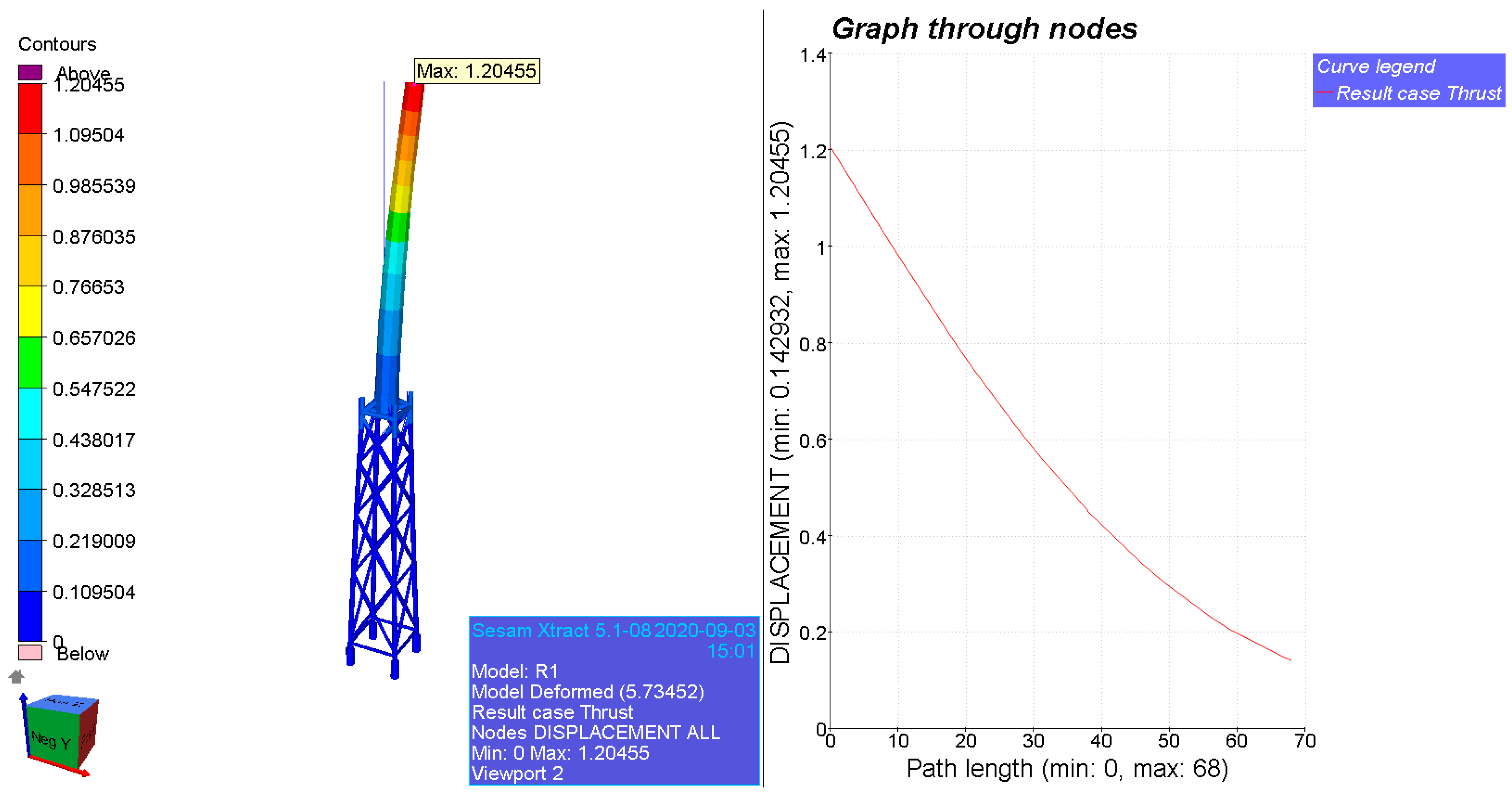
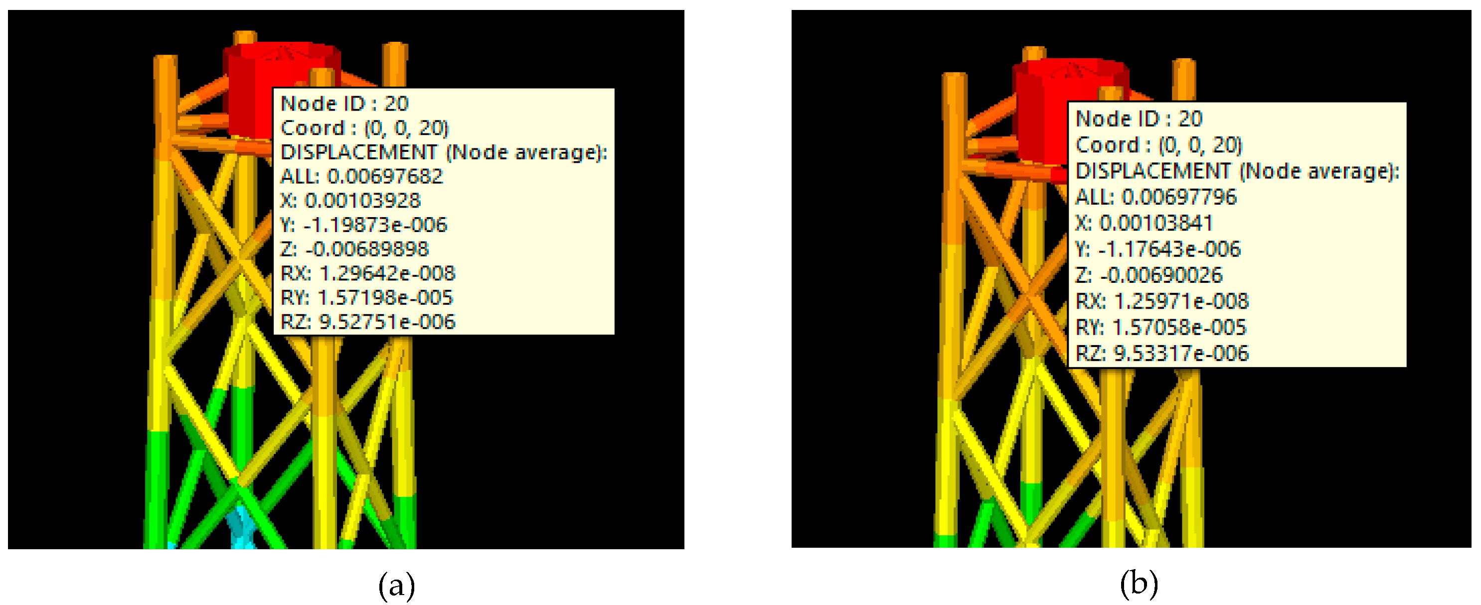
In order to perform the super-element analysis, the super-element model should also show spatial convergence, i.e., show similar behaviour under the same loading condition. A simulation is performed in SWM on the original model under a specific load, and displacement at the interface point is noted. Moreover, another simulation is performed on a super-element model to observe the displacement at the interface node under the same loading conditions. The results are compared in the Xtract module at t = 25 s and show good accuracy, as shown in
Figure 7.
4.1.2. Bladed
An aero-hydroservo-elastic solver like Bladed is needed to simulate the coupled dynamic response of an offshore wind turbine. This complex simulation captures the interaction of a multi-physics system and simulates a holistic model in a coupled manner [
41]. For defining the wind loads, each wind speed is simulated for a period of 200 s. The turbulence can be modelled in the software to include temporal and spatial variations. The wind loads in this study are simulated by ignoring any variations in the wind because of the computational cost. Turbine wake is not modelled in such simulations because only one wind turbine is being simulated. Although the super-element approach excludes hydro-servo interaction, the verification report [
40] shows similar results by integrated and super-element approaches [
42]. This super-element model was exported, where it was attached at the interface point to the NREL 5-MW wind turbine. NREL 5-MW wind turbine was fully defined in Bladed, including blade geometry, airfoil sections, rotor, hub, nacelle, and tower.
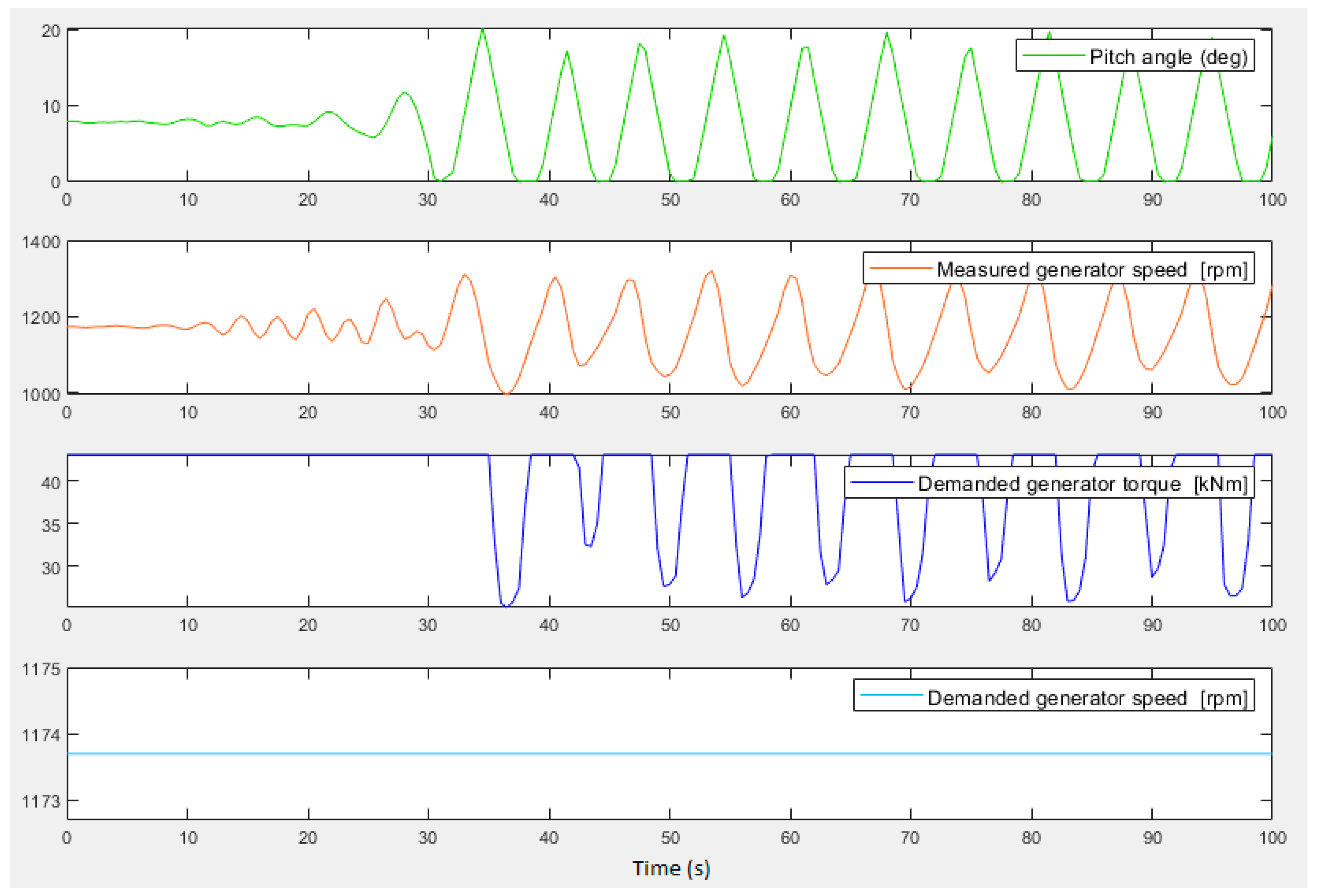
The Bladed software can generate simple time-series loads with the built-in controller. However, the fatigue damages were relatively high because of the complex nature of FLS analysis. The light and dark blue lines (
Figure 8) show demanded generator speed and torque and are constant initially. However, the measured generator speed (orange) fluctuated around the demanded generator speed later in the simulation. The controller tries to correct this by pitching the blades (the green line fluctuates between 0 and 20°), but it over-corrects and exacerbates the oscillation in generator speed. An external controller for the NREL 5-MW wind turbine was implemented to improve the accuracy of fatigue results.
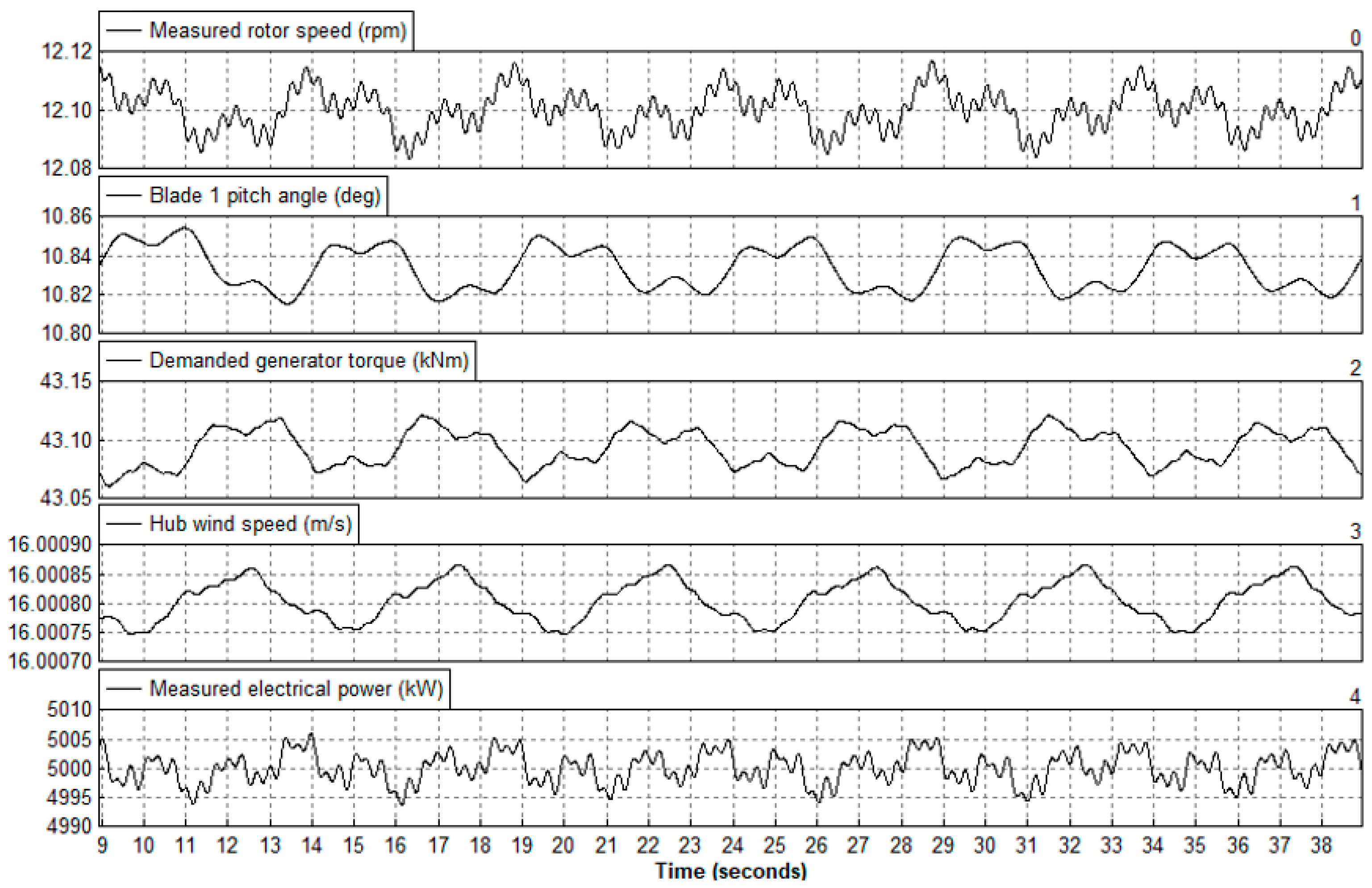
Figure 9 shows the stabilised blade pitch angle for a demanded generator torque. It shows the need to design and implement an external controller to improve the accuracy of complex FLS simulations. It was also observed that the blade pitch angle increases at higher wind speeds but remains constant at a given wind speed.
4.1.3. FLS Simulation
The time-series load data from Bladed was then exported to SWM again to generate time-series stress. There are several methods to model the wave loads, as described in [
43,
44]. However, the structures having strong dynamic responses, like OWTs, require stochastic modelling of the sea states and their kinematics [
45]. The significant wave height and mean crossing period define the wave energy spectra characteristics for OWTs [
19]. The wave energy spectra for this study are given in
Table 8. The stress concentration factors (SCF) were calculated based on the Efthymiou principle on each tubular joint. The calculation of SCFs considers the joint’s geometry and the nature of applied loads. The software uses the method to calculate SCF as given in the standard DNVGL-RP-C203 [
44]. Based on the SCFs and the time series of loads, stresses on the joints are calculated based on the hotspot stress approach.
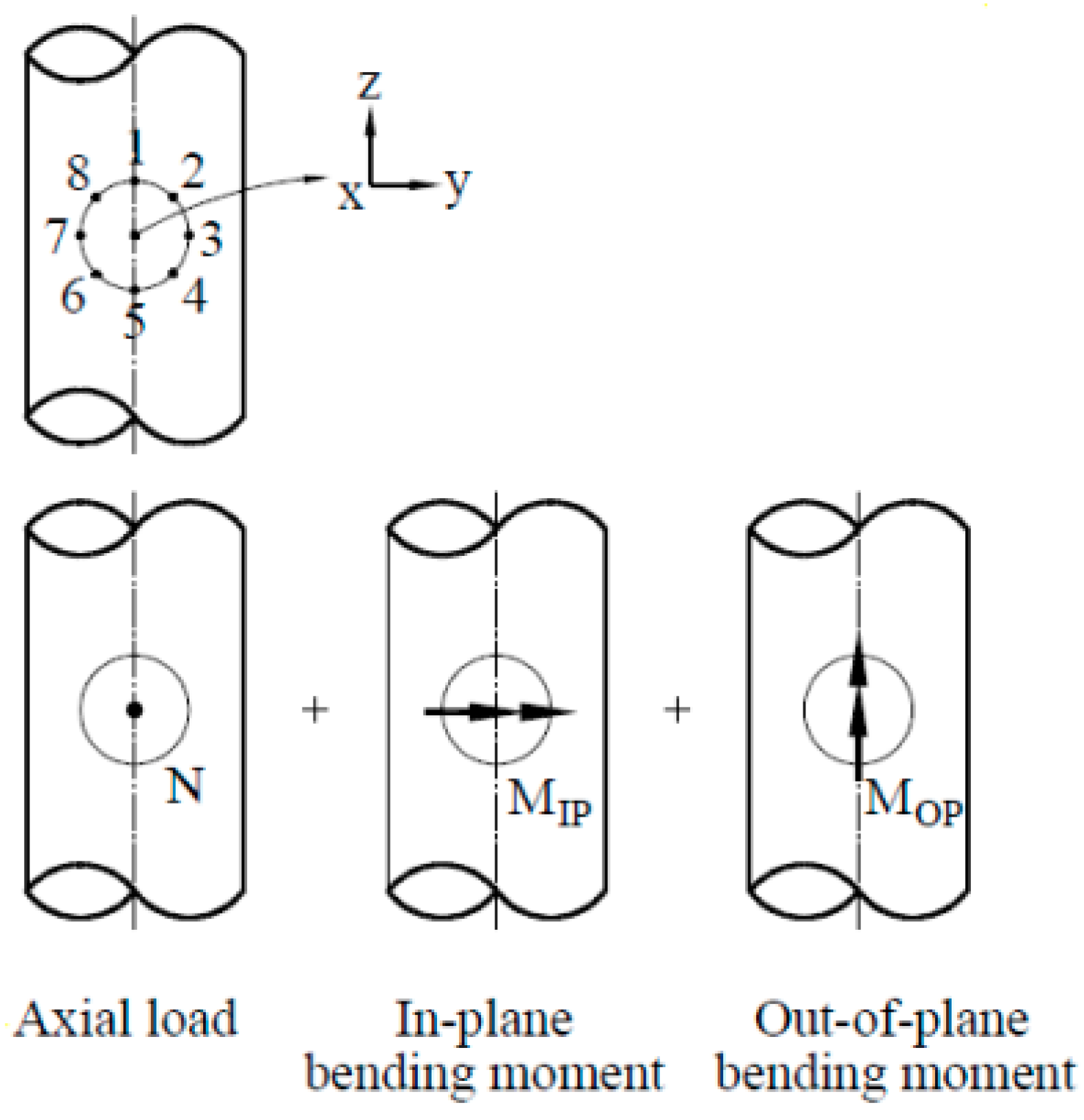
Figure 10 shows the location of hotspots on the brace. The highest value of the eight locations on the circumference for each simulation was selected for the calculations [
38]. Miner’s rule was used to calculate the total damage at each joint after obtaining the time series of stress ranges. The calculation of damages is based on a user-selected S-N curve.
Figure 11 shows the flowchart of modules used to generate fatigue time-series results.
5. Results and Discussion
The modelling parameters significantly affect the dynamic behaviour of the jacket, which also affects the fatigue life. Optimising the stiffness-to-mass ratio by varying design parameters to reach the perfect design is a typical feature of effective structural design. It is crucial to identify the parameters affecting the dynamic behaviour of the model. The effect of modelling parameters like marine growth, flooding, soil profile, the mass TP, the material of TP, scour development, and the length of grouted connection on the dynamic response was studied and discussed below.
The effect of these design parameters was also studied on the fatigue life of the jacket foundation. For this purpose, the fatigue life was compared for all the joints. Since the jacket design has much redundancy, the fatigue life of the second worst-performing joint has been considered a failure. The location of the worst-performing joint is on the x-brace, as shown in
Figure 12. The fatigue damage value of 1 represents when the jacket’s crack initiates, which leads to failure. Moreover, the effect of different grouted connection configurations on the time-series fatigue life of the jacket has also been studied.
5.1. Soil
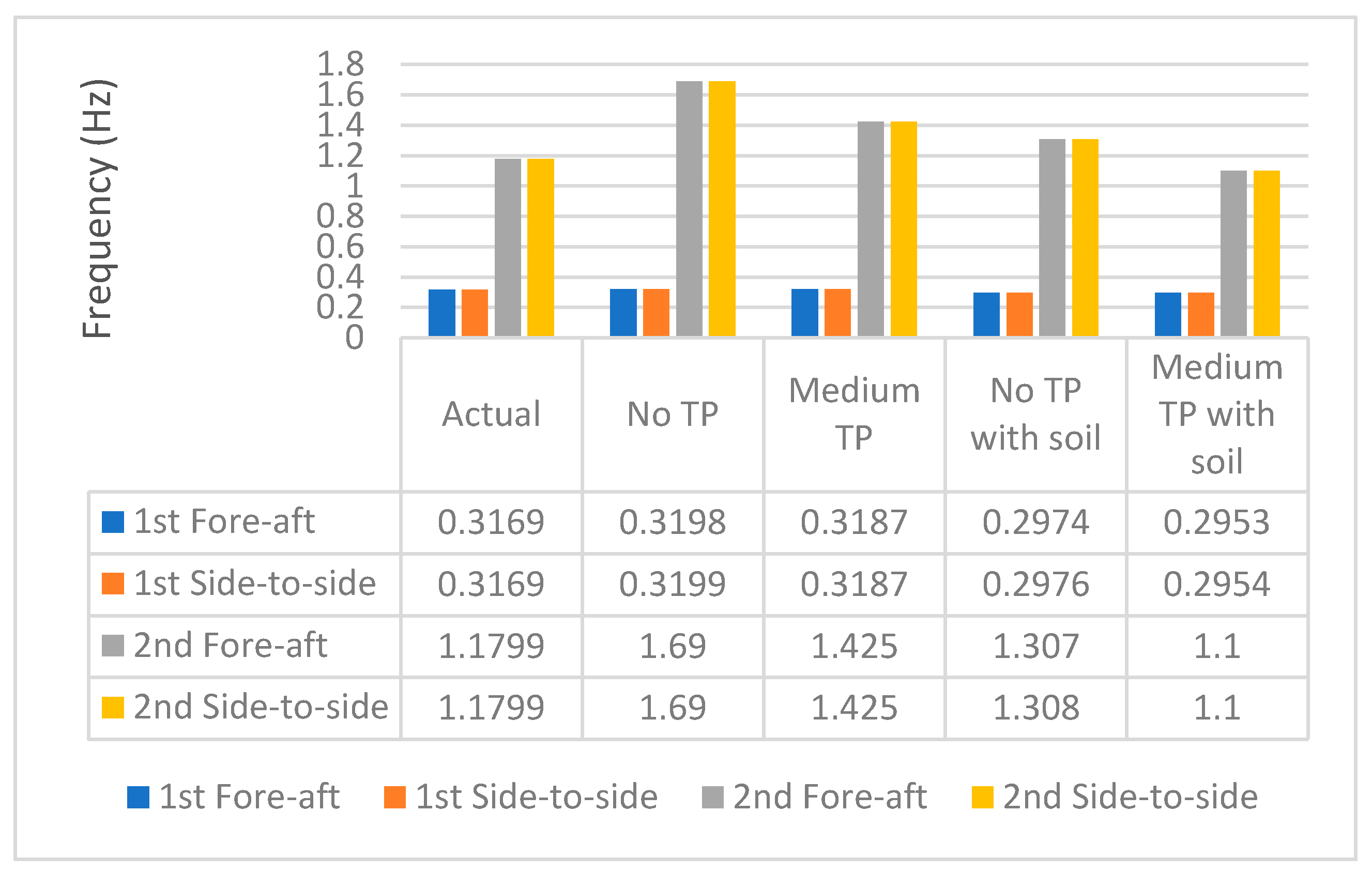
The Original OC4 jacket foundation is linear and clamped at the base without any soil. The soil profile of the site selected in the North-sea was modelled in Genie and compared with the first four natural frequencies of the original model. It can be observed that the natural frequency of all the modes is lower than that of the original model (
Table 5). This phenomenon is because soil stiffness is lower, and the structural behaviour is more flexible; hence, the eigenvalue frequencies will be lower. The trend agrees with the findings of the study [
46].
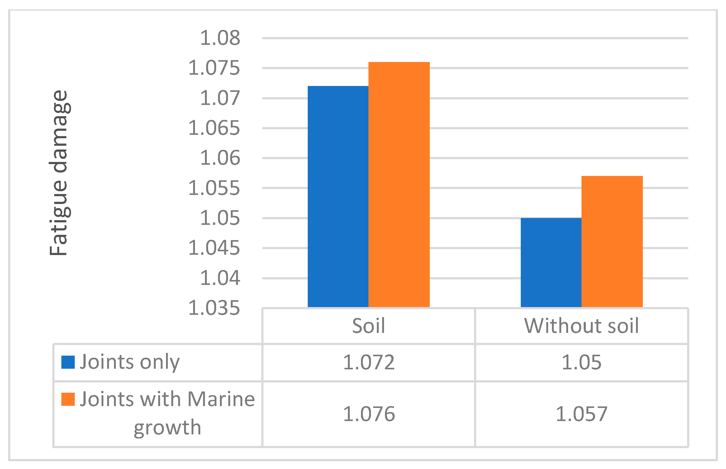
Figure 13 shows the dynamic response and
Figure 14 shows the damage of soil and non-soil models respectively. The damage is greater when the soil non-linearity is included in the model because of the lower stiffness and higher amplitude vibrations.
5.2. Marine Growth
Various marine growth mechanisms develop in the submerged jacket members, affecting the structural response because of the added structural area and the change in surface roughness. The marine growth was introduced in the model from the water depth of 2 to 40 m, with an increased density of 1100 kg/m
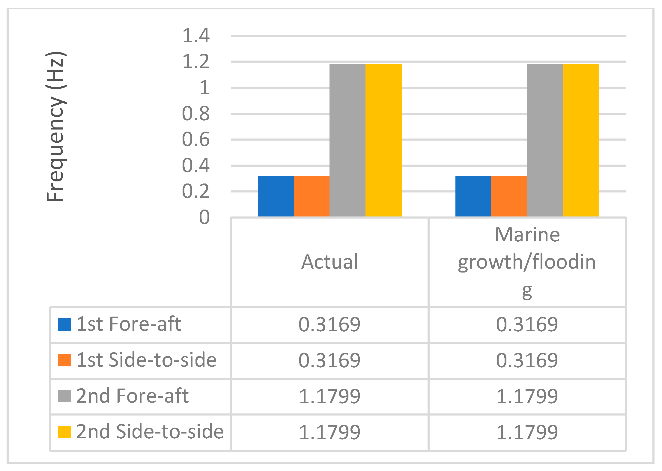
3 and thickness of 100 mm as per the guidelines of the DNV standard. It is observed that adding the marine growth has not changed the stiffness (
Figure 15), and the effect on fatigue life (
Figure 14) is not significant either. The fatigue damage may be slightly greater because of the increased SCF.
5.3. Transition Piece
A TP connects the jacket foundation with the tower, and its design significantly affects the dynamic response and fatigue life. Two primarily used configurations are a stiff concrete block and a light frame design. The OC4 jacket foundation has a concrete TP, but Genie can not model a concrete block. The TP was modelled as a beam with increased stiffness and an added mass of 628,107 kg to simulate a similar effect. Moreover, the impact of TP on the dynamic response and fatigue is studied based on three configurations. The medium configuration has a mass of 314,203 kg, and No TP configuration excludes the point mass. An additional configuration was also studied by including Steel TP (actual stiffness), and its effect on fatigue life is discussed below.
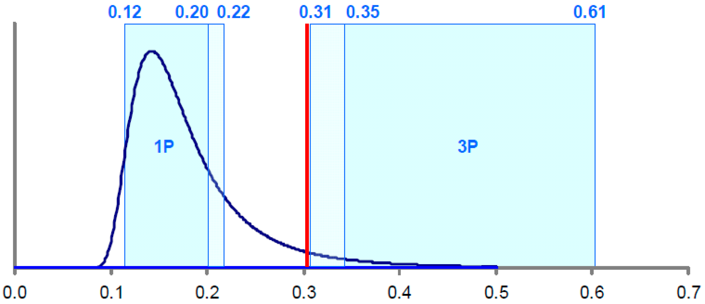
The first and second natural frequencies are close to the 1P and 3P rotor frequencies and are not impacted much by the change in mass (
Figure 16). This trend follows the findings given in [
47]. However, the effect is significant on the third and fourth natural frequencies.
The FLS check shows that the higher mass increases the axial force and moments on the joints, hence increasing fatigue damage (
Figure 17). It is also observed that the fatigue damage decreases significantly when the whole TP is made of steel. The damage is lower due to the lighter TP and the absence of irregular material change in TP, which reduces the stress on joints.
5.4. Scour
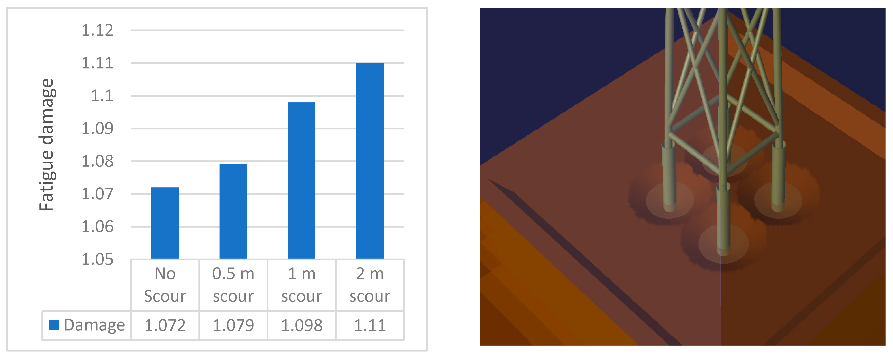
Seabed scour occurs near the intersection of piles with the soil. Scour is governed by structural geometry, fluid flow, and seabed conditions. The study assumes that the scour has already formed and does not investigate the phenomena of scour formation because it is outside the scope of this study. Three different configurations of scour are considered, which affect the values of spring stiffness showing the soil model.
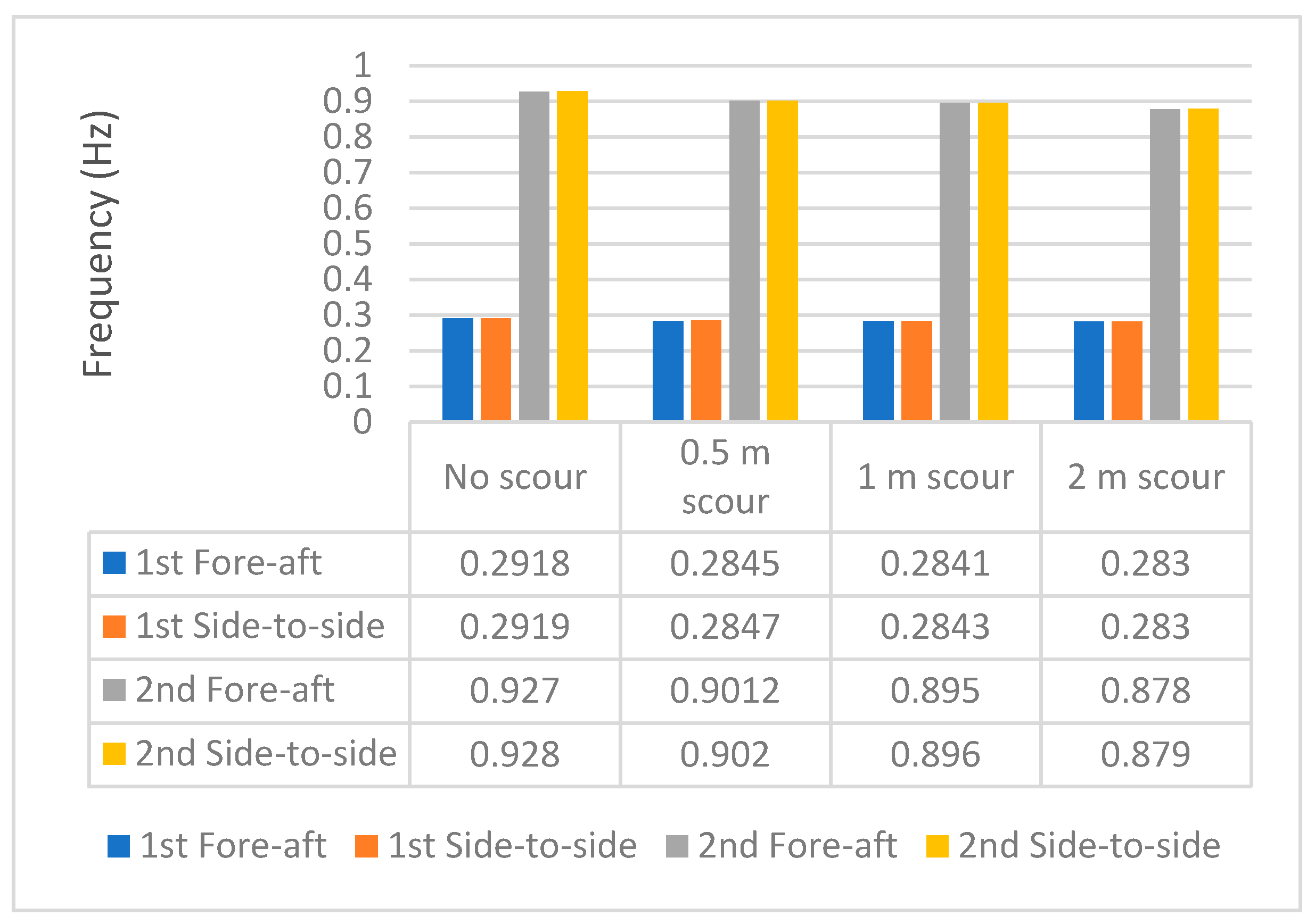
Scour can affect the structural integrity because the embedded area of the jacket is lower, which results in lower support. This phenomenon results in lower stiffness and eigenvalue frequencies.
Figure 18 shows that the effect is insignificant on the first fore-aft and side-to-side frequencies. However, there is a reduction in third and fourth eigenvalue frequency. There is a reduction of 0.70, 1.32, and 3.20% for 0.5, m, and 2 m of scour, respectively.
As expected, the lower support produces greater damage to the structure. The damage increases with the scour size (
Figure 19) as it increases the stress range. It is worth noting that the increase in the damage with the scour size is not steep. Few soil types (low cohesion) can produce significant damage if the scour phenomenon is not mitigated. This asks for the need to perform frequent scour prevention and mitigation measures [
47].
5.5. Grouted Connection
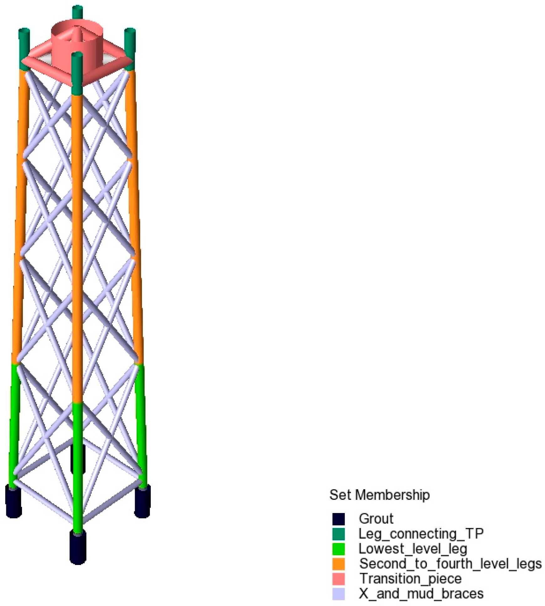
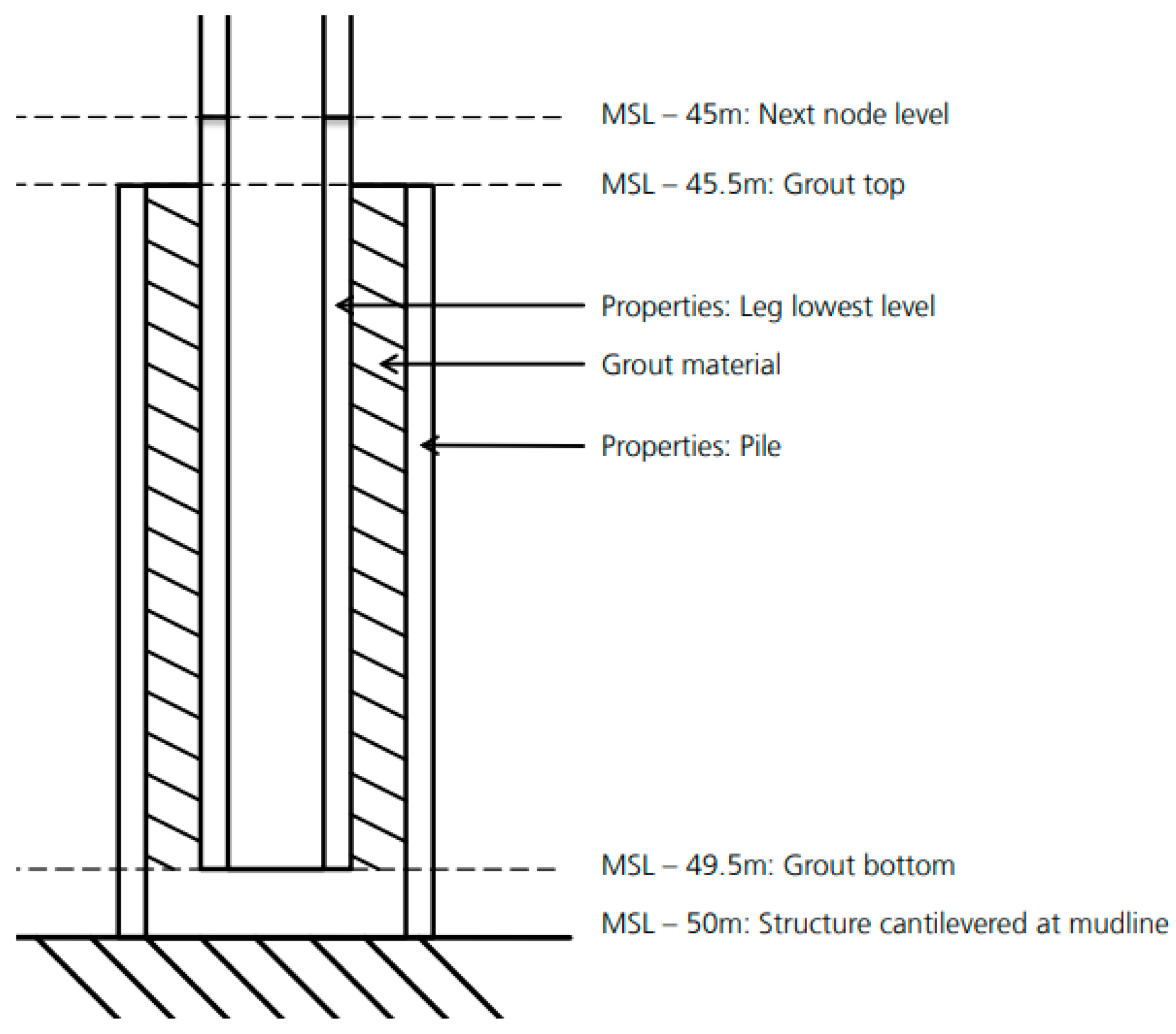
The OC4 jacket foundation is cantilevered at the mudline with a grouted connection. The grouted connection consists of the pile, jacket leg, and the two tubular members, and these are connected with a grout material (density = 2000 kg/m
3) filled at each joint. The DNV practice recommends two concepts for the grouted connection design, i.e., inclined pile in leg and leg in a pile (see
Figure 20). The inclined leg in the pile model has a pile diameter less than the leg, while the diameter of the pile is greater than the leg in the leg in a pile model.
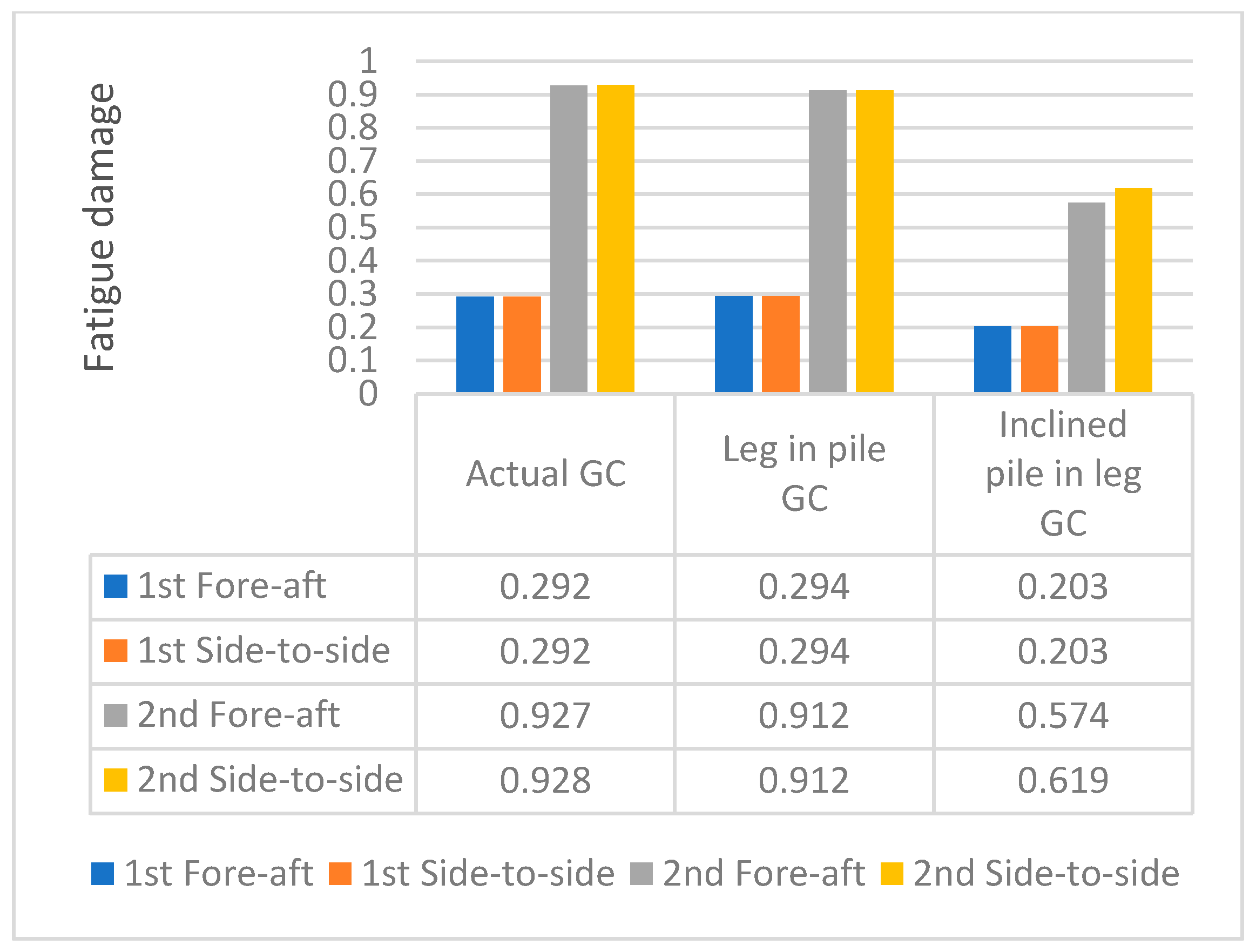
The original design of the OC4 foundation has a leg in a pile configuration, and the length of the grouted connection is 4 m. Two modified configurations of grouted connections were simulated. In one model, the length of grouted connection was increased to 6 m in the leg in a pile configuration, such that the hub height increased from 88.15 m to 90.15 m. The pile diameter was kept the same as in the original model (2.082 m). The second model has an inclined pile in leg configuration with a pile diameter of 0.9 m. The first two eigenvalue frequencies were not altered much in the leg in a pile model, but there was a decrease of 2.16% in the third and fourth natural frequencies (
Figure 21). However, there was a significant decrease in the eigenvalue frequencies in the inclined pile in a leg model. The first two natural frequencies were inside the 1P rotor frequency range, which is a soft structure, as discussed in [
48] and [
49].
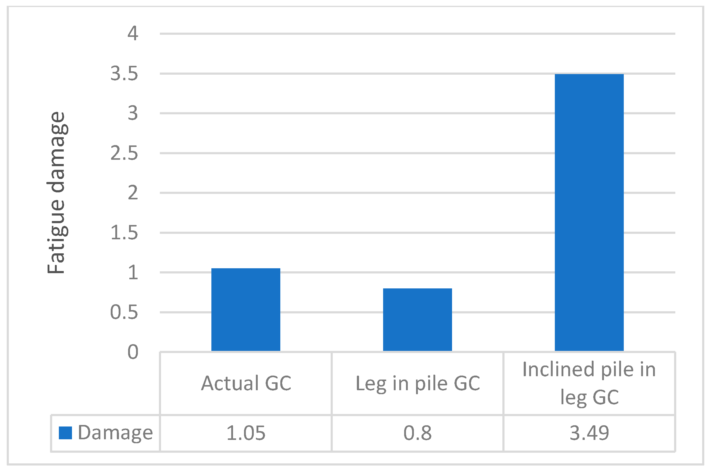
The fatigue damage has considerably reduced for the leg in a pile configuration with an increased grouted connection size (
Figure 22), which is expected because it has greater support at the bottom. However, the damage is considerably greater for the inclined pile in a leg configuration because the 1P frequency is closer to the natural frequency of the rotor. Moreover, the structure is also not stiff enough to provide good support. Another interesting observation was that the highest damage point was on an x-brace around the middle of the jacket, which has moved to the braces at the bottom of the jacket. Additionally, the damage at the previous point of reference has slightly increased to 1.08.
6. Conclusions
In this study, the effect of different parameters on the structural response of the jacket foundation was observed in terms of dynamic response and fatigue life. The OC4 jacket foundation was developed in Sesam and validated with previous research. The validated model was converted to the super-element model and exported to Bladed, where it was attached to an NREL 5-MW wind turbine. The time-series wind and wave loads were simulated in Bladed to obtain the time-series loads. These time-series loads were exported to the SWM, where FLS analyses were performed. The steps were repeated by keeping identical wind/wave loads, and the effect of marine growth, non-linearity of soil, transition piece’s mass and material, scour size, and the length of grouted connection on the dynamic response and fatigue damage was observed by considering the life of 20 years. The fatigue damage of 1 implies that a crack has fully developed.
It was observed that the effect of marine growth was minimal on the structural dynamic response and fatigue damage. However, the non-linearity of the soil has a significant impact on the dynamic response. The original OC4 jacket foundation has a fixed base, and a soil profile of the north sea was included in the model. The damage of the non-linear model is greater than the original model because of the lower stiffness of the soil model, which results in vibrations of higher amplitude. The effect of non-linearity was further extended to include the scour of different sizes (0.5, 1, and 2 m). The effect of the scour size was insignificant on the first two natural frequencies, but there was a reduction of 3.2% in the third and fourth natural frequencies for a scour of 2 m. The values reduced by 0.7% and 1.32% for the scour sizes of 0.5 and 1 m, respectively—the reduction in the support due to scour caused the damage to increase.
The study also observed the effect of changing the design in the form of the transition piece and grouted connection. The TP with three mass configurations showed that the third and fourth eigenvalue frequencies change significantly, and an inverse relationship was observed between the mass and frequencies. However, the first two frequencies were not altered. The fatigue damage was greater for the heavier TP because of the higher axial force and moments on the joints, which resulted in higher stresses. The material selection between the concrete TP and steel TP showed the need to move to the lighter steel frames to extend the fatigue life.
A unique set of simulations were performed by increasing the length of the grouted connection from the original grouted connection size of 4–6 m for a leg in a pile configuration; this resulted in the increase of the hub height to 90.15 m. The overall effect was an increase in fatigue life because of the greater support. The design configuration was also changed to an inclined pile in a leg; this resulted in the reduction of the first two eigenvalue frequencies near the 1P range. This resulted in a steep rise in fatigue damages near the lower part of the jacket. In terms of fatigue damage, marine growth has a minimum effect and can be ignored. However, the introduction of non-linearity along with scour should be included to increase the accuracy of the results. Moreover, the study recommends the need to adopt steel TP instead of concrete. The length of grouted connection for a leg in a pile configuration can be increased to increase the fatigue life.
An effort was made to minimise the simplifications in the design, which is usually the case due to the cost and complexity of such simulations. This research adds to knowledge by examining the influence of a unique combination of changes in the design, material of the transition piece, and grouted connection on dynamic response and fatigue life. The research also presents in-depth information on the sophisticated design of FLS analysis utilising the super-element approach (mostly used in industry). Future work should include the effect of turbulence intensity and wave-current to improve the results. There is also a scope to study the effect of the diameter and thickness of the members on the structural response. The parameters that can significantly impact the design life of jacket foundations were identified. This can help in extending the design life as well as reduce costs. The increased number of parameters and design changes observed in the TP and grouted connection in the complex time-series simulations significantly contribute to knowledge. The FLS analysis helps identify the weaker joints, and the damage parameter of 1 is considered a failure. However, in reality, it shows that the crack has been initiated, and the structure has not failed. Future work may include crack propagation and fracture mechanics principles to study the actual failure of the joint.
