
A Review of Progress and Applications of Automated Vacuum Mooring Systems

Abstract
:1. Introduction
2. Automated Vacuum Mooring System
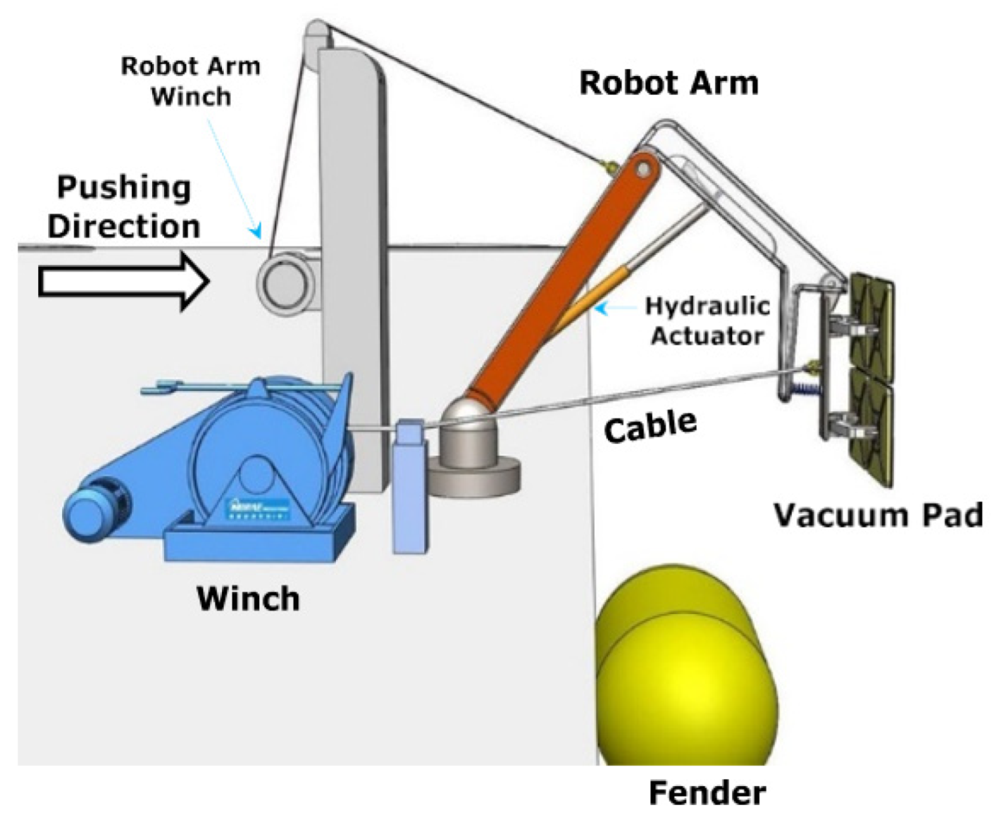
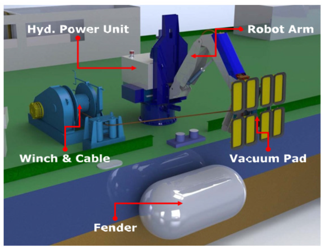
2.1. Components
2.2. Working Principles
2.3. Advantages
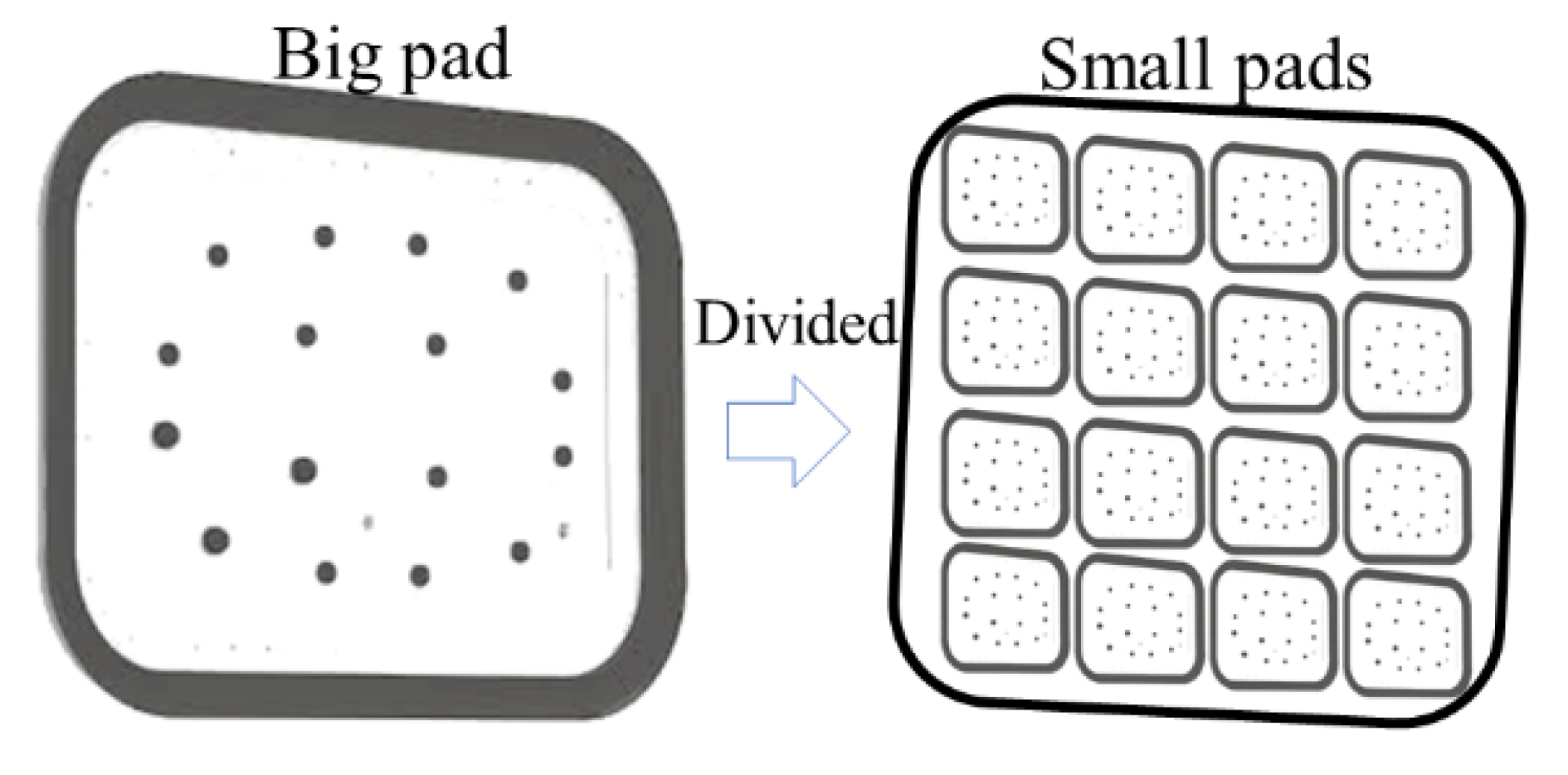
- Works with virtually all vessels. The vacuum pad has a modular design and can be attached to the plane of the hull [32].
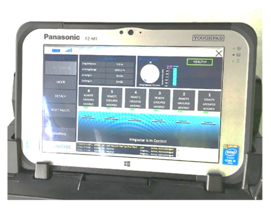
- High degree of automation and more safety. The operator only needs to press the control button to complete the automated mooring operation through the remote-control system. Since there are no snap-back zones in this mode of operation, personnel do not need to work in hazardous areas, thus this system can guarantee zero accidents for personnel (Figure 8).
- 4.
- Vessel overhang. Since the birth of the MoorMasterTM, the berthing of large ships no longer requires additional infrastructure investment in the port, only the addition of some automated vacuum mooring systems. Dock length can easily be changed by increasing the number of devices. Ships of any tonnage can use these berths.
- 5.
- Stability. There is reduced vessel motion due to the advanced control system. Research shows that the range of the vessel motion in surge and sway when using mooring lines is 1.1 m and 0.77 m, respectively, when using 6 × T40′s and 12 × T40′s of an automated vacuum mooring system. The range of the vessel motion in the surge is 0.64 m and 0.29 m, respectively, and in sway this range is 0.7 m and 0.44 m, respectively [24].
- 6.
- Economy. At present, the automated vacuum mooring system is installed in 23 docks in 12 different countries [31], and the system does not require ropes and mooring persons. Time loading and unloading can be saved, and the turnover rate of ships is accelerated, thus more ships can be berthed in the port per unit time. This saves the start time during transfer and reduces the workload of mooring personnel. The application of an automated vacuum mooring system reduces injury to mooring personnel and avoids the need for large amounts of compensation, thereby producing good economic benefits.
- 7.
- Environment. Emissions of polluting gases, especially carbon dioxide, are reduced as the automated vacuum mooring system can berth in less time [36]. At present, new European regulations [37,38] impose restrictions on the emissions of greenhouse gases (CO2) and harmful pollutants from ships. In traditional mooring systems, ship emissions are affected by the following factors: the machine regime or the speed control [39,40,41], the quality of the fuel used, the conservation of the ship and the hull [42,43], and the time taken to carry out the maneuvers. However, with the installation of an automatic vacuum mooring system, CO2 emissions were reduced by 97%. There are two methods for analyzing the reduction of CO2 emissions in ports where automatic mooring systems are installed, namely, the EPA methodology [44] and the ENTEC methodology [45,46,47,48]. Both methods are considered suitable [49,50]. Taking the Salalah, Beirut, and Ngqura ports as examples, the CO2 emissions of conventional mooring and automated vacuum mooring systems were calculated using both ENTEC and EPA methods (Table 1). From 2009 to 2019, CO2 emissions from ports worldwide have decreased by 944,241,2160 tons due to the adoption of automated vacuum mooring system technology. With the installation of an automatic vacuum mooring system, CO2 emissions were reduced by 98% (Table 2) [34].
2.4. Limits and Risks
3. Applications
3.1. Ship-Based System
3.2. Shore-Based System
4. Routine Maintenance
5. Discussion, Challenges, and Future Perspectives
5.1. Discussion
5.2. Automated Vacuum Mooring Systems Face Many Challenges
5.3. Future Perspectives
5.3.1. Theoretical Mathematic Models of Automated Vacuum Mooring Systems
5.3.2. Structurally Improved Automated Vacuum Mooring System to Suit Various Port and Marine Conditions
6. Conclusions
Author Contributions
Funding
Institutional Review Board Statement
Informed Consent Statement
Data Availability Statement
Acknowledgments
Conflicts of Interest
Appendix A

References
- Amaechi, C.V.; Wang, F.; Ye, J. Mathematical Modelling of Bonded Marine Hoses for Single Point Mooring (SPM) Systems, with Catenary Anchor Leg Mooring (CALM) buoy application—A review. J. Mar. Sci. Eng. 2021, 9, 1179. [Google Scholar] [CrossRef]
- He, S.; Wang, A. Time and Frequency Domain Dynamic Analysis of Offshore Mooring. J. Mar. Sci. Eng. 2021, 9, 781. [Google Scholar] [CrossRef]
- Huang, W.-H.; Yang, R.-Y. Water Depth Variation Influence on the Mooring Line Design for FOWT within Shallow Water Region. J. Mar. Sci. Eng. 2021, 9, 409. [Google Scholar] [CrossRef]
- Shakhov, V.V.; Yurgenson, A.N.; Shakhov, V.V.; Yurgenson, A.N. Towards Edge Computing Based Monitoring for Smart Ports. In Proceedings of the International Conference on Computational Science and Its Applications—ICCSA 2021, Cagliari, Italy, 13–16 September 2021; Lecture Notes in Computer Science. Springer: Cham, Switzerland, 2021; Volume 12958, pp. 262–271. [Google Scholar] [CrossRef]
- Üzel, M. Cavotec Wins Breakthrough Automated Vacuum Mooring Order in Far East. 2021. Available online: https://www.mynewsdesk.com/cavotec/pressreleases/cavotec-wins-breakthrough-automated-vacuum-mooring-order-in-far-east-3101459 (accessed on 20 July 2022).
- DNV; Li, Y. A New Look at Safe Mooring. 2020. Available online: https://www.dnv.com/expert-story/maritime-impact/A-new-look-at-safe-mooring.html (accessed on 20 July 2022).
- UK P&I Club. Risk Focus Consolidated 2016: Identifying Major Areas of Risk. 2016. Available online: https://www.ukpandi.com/news-and-resources/articles/2016/risk-focus-consolidated-2016/ (accessed on 20 July 2022).
- Kuzu, A.C.; Arslan, Ö. Analytic Comparison of Different Mooring Systems. In Proceedings of the Global Perspectives in MET: Towards Sustainable, Green and Integrated Maritime Transport, Varna, Bulgaria, 11–14 October 2017; pp. 265–274. [Google Scholar]
- Popesco, O. Automating the Mooring Process. 2009. Available online: https://aapa.files.cms-plus.com/SeminarPresentations/2009Seminars/09Facilities/09FACENG_Popesco_Ottonel1.pdf (accessed on 20 July 2022).
- Ma, K.; Shu, H.; Smedley, P.; L’hostis, D.; Duggal, A.S. A Historical Review on Integrity Issues of Perma Permanent Mooring Systems. In Proceedings of the Offshore Technology Conference, Houston, TX, USA, 6–9 May 2013. [Google Scholar] [CrossRef]
- Van Bonifacio, J.; Van der Meijden, F.; Sprenger, G.; Sproot, D. Alternative Berthing: Improvement and Innovation; Maritime Symposium: Roterdam, The Netherlands, 2014. [Google Scholar]
- Gao, F.; Hu, K.; Shen, W.; Li, Y. Study on the Safety Guarantee of Ship Mooring from Frequent Cable Accidents. IOP Conf. Ser. Earth Environ. Sci. 2021, 621, 012007. [Google Scholar] [CrossRef]
- Brindley, W. Mooring Rope Snapback Simulation. 2022. Available online: https://ore.catapult.org.uk/blog/mooring-rope-snapback-simulation/ (accessed on 20 July 2022).
- Shapovalov, K.A.; Shapovalova, P.K. Traumatism During Mooring Operations on Vessels. Ann. Mar. Sci. 2020, 4, 030–034. [Google Scholar] [CrossRef]
- The Maritime Executive. Majority of Mooring Accidents Caused by Lines Parting. 2015. Available online: https://maritime-executive.com/article/majority-of-mooring-accidents-caused-by-lines-parting (accessed on 20 July 2022).
- Erkan, Ç. Fatal and Serious Injuries on Board Merchant Cargo Ships. Int. Marit. Health 2019, 70, 113–118. [Google Scholar] [CrossRef]
- Poisson, M. Safety Issues Associated with Mooring Operations in the Maritime Industry. 2017. Available online: https://www.tsb.gc.ca/eng/securite-safety/marine/2018/m17c0060/m17c0060.html (accessed on 20 July 2022).
- CHIRP Maritime. Maib Accident Reports Reference Library. 2022. Available online: https://www.chirpmaritime.org/reference-library/ (accessed on 20 July 2022).
- Registry, C. Accidents and Incidents Reported to MACI (2020). 2021, pp. 1–12. Available online: https://www.cishipping.com/policy-advice/casualty-investigations (accessed on 20 July 2022).
- Cavotec. Automated Mooring. 2022. Available online: https://www.cavotec.com/en/your-applications/ports-maritime/automated-mooring (accessed on 20 July 2022).
- Cavotec. MoorMaster Automated Vacuum Mooring System. 2022. Available online: https://www.cavotec.com/en/video/moormaster-automated-vacuum-mooring-system (accessed on 20 July 2022).
- Cavotec. MoorMaster NxG. It’s Time to Rediscover Vacuum Mooring. 2022. Available online: https://www.cavotec.com/en/video/moormaster-nxg-its-time-to-rediscover-vacuum-mooring (accessed on 20 July 2022).
- Villa-Caro, R. Sistemas De Amarre En Buques: Situación Actual y Evolución Futura. Ph.D. Thesis, Universidade da Coruña, Coruña, Spain, 2015. [Google Scholar]
- Trelleborg. AutoMoor. 2022. Available online: https://www.trelleborg.com/en/marine-and-infrastructure/products-solutions-and-services/marine/docking-and-mooring/automated-mooring-systems/automoor (accessed on 20 July 2022).
- Cavotec. Automated Mooring Systems. 2022. Available online: http://www.cavotec.com.ua/download/cat9/AMS.pdf (accessed on 20 July 2022).
- Cavotec MSL Holdings Limited. Automated Mooring Method and Mooring System. Patent Registration No. US-8408153B2, 2013. (Application date 24 March 2010; Granted date 2 April 2013).
- Kim, Y.Y.; Choi, K.-J.; Chung, H.; Han, S.; Lee, P.-S. A ship-to-Ship Automatic Docking System for Ocean Cargo Transfer. J. Mar. Sci. Technol. 2014, 19, 360–375. [Google Scholar] [CrossRef]
- Cavotec. Automated Mooring. 2014. Available online: https://www.cavotec.com/zh/your-applications/ports-maritime/automated-mooring/ropax-roro (accessed on 20 July 2022).
- BS 6349-4: 2014; BSI Standards Publication Code of Practice for Design of Fendering and Mooring Systems, 3rd ed. BSI: London, UK, 2014.
- Son, Y.; Kim, M.S.; Jang, H.; Kim, S.; Kim, Y. Study on Temperature Dependent Mechanical Properties of Chloroprene Rubber for Finite Element Analysis of Rubber Seal in an Automatic Mooring System. J. Soc. Nav. Archit. Korea 2022, 59, 157–163. [Google Scholar] [CrossRef]
- Cavotec. Alternative Berthing Improvement and Innovatiaon. 2022. Available online: https://www.cavotec.com/en/your-applications/ports-maritime/automated-mooring (accessed on 20 July 2022).
- Ignacio, H.S. Sistema Automático De Amarre Por Vacío: Implementación y Análisis Para el Buque Volcán del Teide; Atribución-NoComercial-SinDerivadas, Creative Commons Corporation: Los Angeles, CA, USA, 2021. [Google Scholar]
- Vedin, N. Parking Up Safely. Maritime Risk International. 2020. Available online: https://www.standard-club.com/fileadmin/uploads/standardclub/Documents/Import/news/2020-news/3376591-mri-2020-dec-jan.pdf (accessed on 20 July 2022).
- Díaz-Ruiz-Navamuel, E.; Ortega Piris, A.; López-Diaz, A.I.; Gutiérrez Miguel, A.; Andres Roiz, M.; Oria Chaveli, J.M. Influence of Ships Docking System in the Reduction of CO2 Emissions in Container Ports. Sustainability 2021, 13, 5051. [Google Scholar] [CrossRef]
- Laura, H. Alternative Mooring Systems. Bachelor’s Thesis, Kymenlaakso University of Applied Sciences, Kotka, Finland, 2016. [Google Scholar]
- Cullinane, K.; Cullinane, S. Atmospheric Emissions from Shipping: The Need for Regulation and Approaches to Compliance. Transp. Rev. 2013, 33, 377–401. [Google Scholar] [CrossRef]
- Kalli, J.; Jalkanen, J.-P.; Johansson, L.; Repka, S. Atmospheric Emissions of European SECA Shipping: Long-term Projections. WMU J. Marit. Aff. 2013, 12, 129–145. [Google Scholar] [CrossRef] [Green Version]
- Chang, C.-C.; Chang, C.-H. Energy Conservation for International Dry Bulk Carriers Via Vessel Speed Reduction. Energy Policy 2013, 59, 710–715. [Google Scholar] [CrossRef]
- Eide, M.S.; Longva, T.; Hoffmann, P.; Endresen, O.; Dalsoren, S.B. Future Cost Scenarios for Reduction of Ship CO2 Emissions. Marit. Policy Manag. 2011, 38, 11–37. [Google Scholar] [CrossRef]
- Eide, M.S.; Dalsoren, S.B.; Endresen, O.; Samset, B.; Myhre, G.; Fuglestvedt, J.; Berntsen, T. Reducing CO2 from Shipping—Do non-CO2 Effects Matter? Atmos. Chem. Phys. 2013, 13, 4183–4201. [Google Scholar] [CrossRef] [Green Version]
- Bocchetti, D.; Lepore, A.; Palumbo, B.; Vitiello, L. A Statistical Approach to Ship Duel Consumption Monitoring. J. Ship Res. 2015, 59, 162–171. [Google Scholar] [CrossRef]
- Celo, V.; Dabek-Zlotorzynska, E.; McCurdy, M. Chemical Characterization of Exhaust Emissions from Selected Canadian Marine Vessels: The Case of Trace Metals and Lanthanoids. Environ. Sci. Technol. 2015, 49, 5220–5226. [Google Scholar] [CrossRef] [PubMed]
- U.S. Environmental Protection Agency. Analysis of Commercial Marine Vessels Emissions and Fuel Consumption Data Paperback; Office of Transportation and Air Quality, U.S. Environmental Protection Agency: Washington, DC, USA, 2000; ISBN -13. [Google Scholar]
- Grebot, B.; Scarbrough, T.; Ritchie, A. Study to Review Assessments Undertaken of the Revised MARPOL Annex VI Regulations; Entec UK Limited: London, UK, 2010. [Google Scholar] [CrossRef]
- Llorca, J.; Gonza lez Herrero, J.M.; Ametller, S.; Pin~eiro Díaz, E. Recomendaciones Para el Proyecto y Ejecución en Obras de Atraque y Amarre; Puertos del Estado: Madrid, Spain, 2012; Available online: https://www.puertos.es/es-es/BibliotecaV2/ROM%202.0-11.pdf (accessed on 20 July 2022).
- Whall, C.; Cooper, D.; Archer, K.; Twigger, L.; Thurston, N.; Ockwell, D.; McIntyre, A.; Ritchie, A. Quantification of Emissions from Ships Associated with Ship Movements between Ports in the European Community; Report for the European Commission; Entec UK Limited: Northwich, UK, 2010. [Google Scholar]
- Díaz, J.M. Un Enfoque Regional Unificado de Respuesta Contra la Contaminacion Marina Por Petroleo en el Pacifico Nordeste. In Proceedings of the International Oil Spill Conference Proceedings, Miami Beach, FL, USA, 15–19 May 2005; pp. 507–511. [Google Scholar] [CrossRef]
- Gonzalez, C.; Pe rez-Labajos, C.A.; Oria, J.M.; Andres, M.A. Methodology Bottom-up for Estimation of the Air Emissions Inventory and Carbon Footprint for Tugboats. J. Marit. Res. 2015, 12, 103–107. [Google Scholar]
- Ortega Piris, A.; Díaz-Ruiz-Navamuel, E.; Pe rez-Labajos, C.A.; Oria Chaveli, J. Reduction of CO2 Emissions with Automatic Mooring Systems. The case of the Port of Santander. Atmos. Pollut. Res. 2018, 9, 76–83. [Google Scholar] [CrossRef]
- Díaz-Ruiz-Navamuel, E.; Piris, A.O.; Pérez-Labajos, C.A. Reduction in CO2 Emissions in RoRo/Pax Ports Equipped with Automatic Mooring Systems. Environ. Pollut. 2018, 241, 879–886. [Google Scholar] [CrossRef] [PubMed]
- Tolsgaard, J. The Modern Port Automate the Mooring Handling. 2022. Available online: https://docplayer.net/167485431-The-modern-port-automate-the-mooring-handling-presenter-jakob-tolsgaard.html (accessed on 20 July 2022).
- Díaz-Ruiz-Navamuel, E.; Ortega-Piris, A.; Pérez-Labajos, C.A.; Andrés, M.A. Wind Safety Limits on Ships Docked with Two Different Mooring Systems. In Developments in Maritime Technology and Engineering; CRC Press: London, UK, 2021; pp. 351–360. [Google Scholar]
- Cavotec. Electric Vessels. 2022. Available online: https://www.cavotec.com/en/your-applications/ports-maritime/automated-mooring/electric-vessels (accessed on 20 July 2022).
- Cavotec. Container. 2022. Available online: https://www.cavotec.com/en/your-applications/ports-maritime/automated-mooring/container (accessed on 20 July 2022).
- Cavotec. Bulk. 2022. Available online: https://www.cavotec.com/en/your-applications/ports-maritime/automated-mooring/bulk (accessed on 20 July 2022).
- Cavotec. Locks. 2022. Available online: https://www.cavotec.com/en/your-applications/ports-maritime/automated-mooring/locks (accessed on 20 July 2022).
- Cavotec. Ship-to-Ship. 2022. Available online: https://www.cavotec.com/en/your-applications/ports-maritime/automated-mooring/ship-to-ship (accessed on 20 July 2022).
- ICT Loket. Monitor. 2015. Available online: http://www.ictloket.nl/kennisbank/monitoren/ (accessed on 20 July 2022).


| PORTS | Ropes/Tons | Automated Vacuum Mooring System/Tons | Reduction/Tons | Reduced Percentage/% RP = (R−ROPE)/ROPE | ||||
|---|---|---|---|---|---|---|---|---|
| ROPEENTEC | ROPEEPA | AENTEC | AEPA | RENTEC | REPA | RPENTEC | RPEPA | |
| Salalah | 7815.3 | 9509.7 | 130.3 | 158.5 | 7685.1 | 9351.2 | 98.3 | 98.3 |
| Beirut | 2568.0 | 3333.5 | 42.8 | 55.6 | 2525.2 | 3277.9 | 98.3 | 98.3 |
| Ngqura | 2574.9 | 3477.1 | 42.9 | 58.0 | 2532.0 | 3419.1 | 98.3 | 98.3 |
| Year | E Ropes/Tons | E Automated Vacuum Mooring System/Tons | AE = E Ropes−E Automated Vacuum Mooring System | AE/E Ropes |
|---|---|---|---|---|
| 2009 | 593,452,606 | 11,869,052 | 581,583,554 | |
| 2010 | 701,869,239 | 14,037,385 | 687,831,854 | |
| 2011 | 760,884,972 | 15,217,699 | 745,667,273 | |
| 2012 | 809,222,136 | 16,184,443 | 793,037,693 | |
| 2013 | 855,160,921 | 17,103,218 | 838,057,703 | |
| 2014 | 898,484,577 | 17,969,691 | 880,514,885 | |
| 2015 | 919,340,019 | 18,386,800 | 900,953,218 | |
| 2016 | 935,487,080 | 18,709,742 | 916,777,339 | |
| 2017 | 1,011,662,659 | 20,233,253 | 991,429,406 | |
| 2018 | 1,065,516,031 | 21,310,321 | 1,044,205,710 | |
| 2019 | 1,084,034,210 | 21,680,684 | 1,062,353,526 | |
| Total | 9,635,114,449 | 192,702,289 | 9,442,412,160 | 98% |
| Port, Country | Berths | Since (Year) | Moorings | LOA (m) | Owner | Operator | Figure | |
|---|---|---|---|---|---|---|---|---|
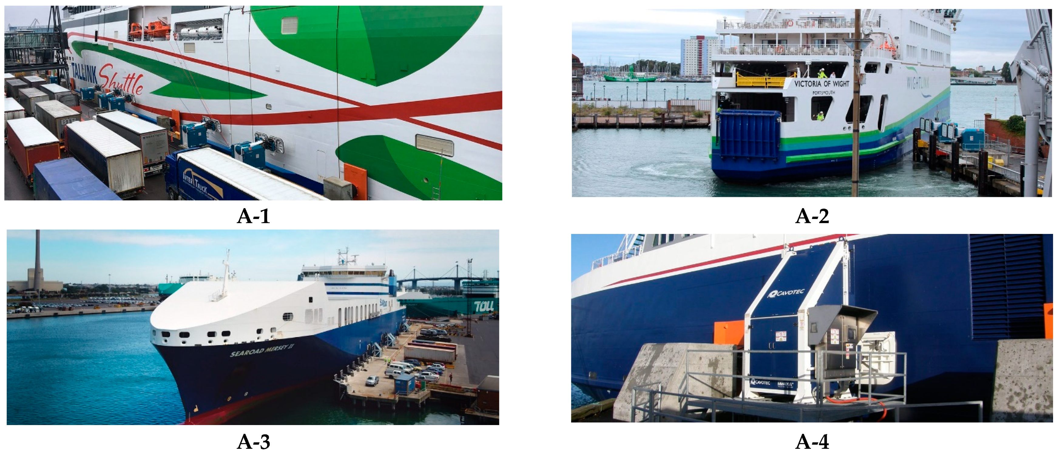
| RoPax and RoRo [28] | Port of Helsinki, Finland (RoPax) | LJ7 and LJ8 | 2017 | 9/day | up to 212 m | Port of Helsinki | Tallink and Eckerö Line | Figure A1(A-1) |
| Wightlink, UK (RoPax) | Portsmouth–Fishbourne | 2017 | 30/day | 62 to 89 | Wightlink | Wightlink | Figure A1(A-2) | |
| Searoad, Australia (RoRo) | Melbourne–Devonport | 2003 | 2/day | 182 to 210 | SeaRoad | SeaRoad | Figure A1(A-3) | |
| Samsø Rederi, Denmark (RoPax) | Hou–Sælvig | 2015 | 7/day | 99 | Samsø Kommune | Samsø Rederi | Figure A1(A-4) | |
| Molslinjen, Denmark (RoPax) | Spodsbjerg–Taars and Ballen–Kalundborg | 2009 | 5/day 18/day | 99 | Molslinjen | Molslinjen | Figure A1(A-5) | |
| Interislander, New Zealand (RoPax) | Picton–Wellington | 2005 | 3/day | 180 to 181 | KiwiRail | Interislander | Figure A1(A-6) | |
| Teso, The Netherlands (RoPax) | Den Helder | 2014 | 16/day | 110 to 130 | Teso | Teso | Figure A1(A-7) | |
| Port of Turku, Finland (RoPax) | Viking Line berth | 2020 | - | up to 222 | Port of Turku | - | - | |
| Port of Tallinn, Estonia (RoPax) | - | 2020 | 9/day | up to 212 | Port of Tallinn | Tallink and Eckerö Line | - | |
| Electric Vessels [53] | Norled, Norway (Two Routes) | Lavik–Oppedal and Sydnes–Utbøya | 2015 | 52/day | 67 to 114 | Norled | Norled | Figure A1(B-1) |
| Asko Maritime, Norway | Horten–Moss | 2022 | 7/day | 58 | ASKO | ASKO | Figure A1(B-2) | |
| Fjord1, Norway (Multiple Routes) | - | 2018 | 50/day | 70 to 110 | Fjord1 | Fjord1 | Figure A1(B-3) | |
| Finferries, Finland (One Route) | Parainen–Nauvo | 2017 | 61/day | 98 | Finferries | Finferries | Figure A1(B-4) | |
| Ærø Ferries, Denmark | Søby–Fynshav–Faaborg | 2019 | 6/day | 60 | Ærø Kommune | Ærø Kommune | Figure A1(B-5) | |
| Ontario Transport, Canada (One Route) | Amherst, Millhaven, Kingston, Marysville and Wolf Island | 2019 | 10/day | 95 | Ontario Transport | Ontario Transport | - | |
| Boreal, Norway (Two Routes) | Kinsarvik–Utne–Kvanndal and Skånevik–Matre–Utåker | 2019 | 11/day | 67 to 75 | Boreal | Boreal | - | |
| FosenNamsos Sjö, Norway (One Route) | Flakk–Rørvik | 2019 | 39/day | 107 | STFK | FosenNamsos Sjö | - | |
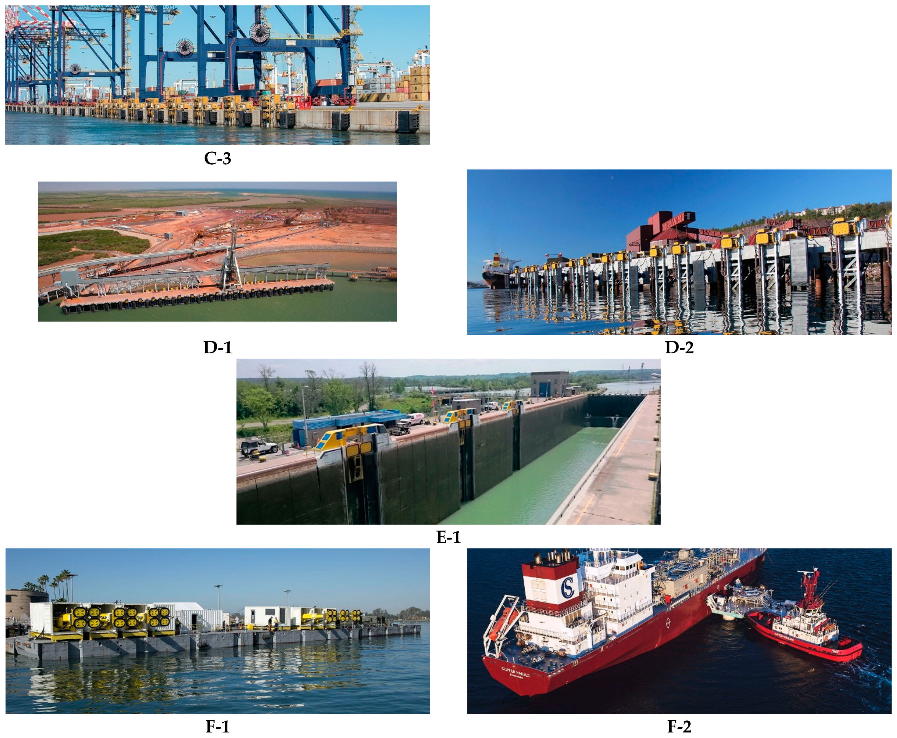
| Container [54] | Port of Salalah, Oman | Transshipment | 2006 | 2–3/day | 400 | Port of Salalah | Port of Salalah | Figure A1(C-1) |
| Port of Beirut, Lebanon | - | 2014 | 4–5/day | 350 | Port of Beirut | Port of Beirut | Figure A1(C-2) | |
| Port of Ngqura, South Africa | - | 2015 | 4–5/week | 366 | Transnet | Transnet | Figure A1(C-3) | |
| Napier Port, New Zealand | 2022 | Napier | Napier | - | ||||
| Bulk [55] | Port Hedland, Australia | Iron ore loading | 2010 | 3–4/week | 295 | Pilbara Ports Authority (PPA) | Pilbara Ports Authority (PPA) | Figure A1(D-1) |
| Port of Narvik, Norway (Lkab) | Iron ore loading | 2016 | 2–4/week | 305 | LKAB | LKAB | Figure A1(D-2) | |
| Econnect Energy (Connect LNG), Norway | LNG transfer | 2017 | - | Vessels with various LOA | Gas Natural | Gas Natural | - | |
| Locks [56] | St. Lawrence Seaway, US and Canada | Lockage | 2014 | 4–5/day | 225 | SLSMC | SLSMC | Figure A1(E-1) |
| Ship-to-ship [57] | US Navy, USA | Navy | 2016 | - | Military vessels | US Navy | US Navy | Figure A1(F-1) |
| Econnect Energy (Connect LNG), Norway | LNG transfer | 2017 | - | Vessels with various LOA | Gas Natural | Gas Natural | Figure A1(F-2) |
Publisher’s Note: MDPI stays neutral with regard to jurisdictional claims in published maps and institutional affiliations. |
© 2022 by the authors. Licensee MDPI, Basel, Switzerland. This article is an open access article distributed under the terms and conditions of the Creative Commons Attribution (CC BY) license (https://creativecommons.org/licenses/by/4.0/).
Share and Cite
Yan, K.; Zhang, S.; Oh, J.; Seo, D.-W. A Review of Progress and Applications of Automated Vacuum Mooring Systems. J. Mar. Sci. Eng. 2022, 10, 1085. https://doi.org/10.3390/jmse10081085
Yan K, Zhang S, Oh J, Seo D-W. A Review of Progress and Applications of Automated Vacuum Mooring Systems. Journal of Marine Science and Engineering. 2022; 10(8):1085. https://doi.org/10.3390/jmse10081085
Chicago/Turabian StyleYan, Kaicheng, Shengdong Zhang, Jungkeun Oh, and Dae-Won Seo. 2022. "A Review of Progress and Applications of Automated Vacuum Mooring Systems" Journal of Marine Science and Engineering 10, no. 8: 1085. https://doi.org/10.3390/jmse10081085
APA StyleYan, K., Zhang, S., Oh, J., & Seo, D.-W. (2022). A Review of Progress and Applications of Automated Vacuum Mooring Systems. Journal of Marine Science and Engineering, 10(8), 1085. https://doi.org/10.3390/jmse10081085