1. Introduction
Many offshore structures have vertical cylindrical supporting columns of circular cross-sections. It is of paramount importance to analyse the wave scattering by such structures and hence calculate the wave loads acting on them. One of the earliest works on this subject is by Twersky [
1], who proposed an iterative procedure for the acoustic wave diffraction problem in which the solution is expressed as the incident wave plus a sum of various orders of scattering. There are also several direct methods of obtaining the water wave forces on multiple cylinders by satisfying the slip boundary conditions on all cylinders simultaneously [
2,
3,
4]. The hydrodynamic interaction problem in the context of water waves has been well-studied. There are many papers devoted to this subject; here, we list only the most important ones. In addition to the direct and iterative methods, there are several numerical methods that are used to investigate the wave–structure interaction in the field of marine engineering. Some of these are the Boundary Element Method (e.g., [
5]), the Finite Element Method (e.g., [
6]), the B-spline panel method (e.g., [
7]), the Finite Difference Method and the Volume of Fluid (VOF) method (e.g., [
8]), and Computational Fluid Dynamics (CFD) investigations (e.g., [
9,
10]). The methods within the hydrodynamic interaction theory make use of Graff’s addition theorem for Bessel functions [
11] to express the diffracted waves from one cylinder as incident waves in the coordinate system of another cylinder. Graff’s addition theorem, in a way, works as a coordinate transformation between the coordinate systems of different cylinders.
The diffraction of hydro-elastic waves by bottom-mounted offshore structures in the sea covered by an ice sheet is a relatively new subject. One of the early works on this subject was undertaken by Fox and Squire [
12]; they solved a two-dimensional problem of ocean waves interacting with a floating ice sheet by the method of vertical modes. It was concluded that the vertical modes are complete but not orthogonal with respect to a standard inner product. Wave scattering by a narrow crack in an ice sheet floating on water of finite depth was studied by Evans and Porter [
13] by the vertical mode method and by a method based on a Green’s function technique. It was concluded that the vertical mode method is easier to use than the Green’s function method and provides the same results. Another relevant two-dimensional hydroelasticity problem deals with the interaction of hydro-elastic waves with a vertical wall [
14,
15]. Brocklehurst et al. [
16] used a Weber transformation to tackle the three-dimensional diffraction problem of hydro-elastic waves by a vertical cylinder. Recently, Korobkin et al. [
17] and Korobkin et al. [
18] solved the problem of hydro-elastic wave scattering with a single cylinder of circular cross-section in an infinite ice cover, implemented both by the vertical mode method and by the Weber integral transform method. It was shown that the two solutions are identical for the clamped edge conditions. Ren et al. [
19] solved the hydro-elastic interaction problem, which involves waves propagating in infinite ice cover and multiple circular cylinders. Graff’s addition theorem was used for coordinate transformation between the cylinders, as it is usually done in hydrodynamic interaction problems involving many cylinders. Each local velocity potential was expanded into a series of eigenfunctions, and the Green’s second identity was then used to impose boundary conditions on each cylinder surface and at the contact lines between the cylinders and the ice sheet. It was stated that an advantage of using Green’s second identity is that it makes application for the edge conditions easier.
In this paper, we propose a new iterative method in which the idea of Gauss-Seidel iteration method for systems of linear algebraic equations is used. This new iterative method is combined with the vertical mode method by Korobkin et al. [
18] to solve the diffraction problem involving multiple circular cylinders and hydro-elastic waves. Comparisons between the wave force results of Ren et al. [
19] and the present results show good agreement, especially in an arrangement of four circular cylinders. It is shown that the new iteration procedure has better convergence characteristics than the Twersky’s multiple scattering technique [
1]. The proposed method is straightforward, intuitive, and physically clear.
2. Formulation of the Problem
A three-dimensional linearized problem of ice loads on
vertical cylinders of circular cross-sections in an ice cover of infinite extent is studied. A hydro-elastic wave propagates in the ice cover towards the rigid cylinders, which are fixed to the sea bottom in finite water depth. The fluid domain,
is the three-dimensional infinite region outside the cylinders,
where
is the water depth,
is the radius of cylinder
, and
is the centre of cylinder
at the ice plate,
(see
Figure 1). The ice sheet,
is the two-dimensional infinite region outside the cross-section of the cylinders at
Similarly, the sea bottom,
is the two-dimensional infinite region outside the cross-sections of the cylinders at
The lateral cylinder surfaces,
are the three-dimensional finite surfaces of the cylinders between the planes
and
The contact lines between the ice cover and the surfaces of the cylinders are the circles
with
The scattering of an incident hydro-elastic wave by the
N circular cylinders is formulated using a velocity potential
which satisfies the Laplace equation in the fluid domain,
the boundary condition at the rigid bottom,
the body boundary condition at the surfaces of the cylinders,
where
denotes the unit outward normal direction (radial direction) for cylinder
and the condition on the ice–water interface,
where
describes the deflection of the ice cover and
are the global cylindrical coordinates,
The deflection is governed by the Bernoulli-Euler equation of a thin elastic plate,
where
is the mass of the ice cover per unit area,
is the constant ice thickness,
is the ice density,
is the rigidity coefficient of the ice plate,
is the Young’s modulus of the ice,
is the Poisson’s ratio, and
is the hydrodynamic pressure given on the ice–water interface by the linearized Bernoulli equation,
where
is the water density and
is the gravitational acceleration.
The ice cover is clamped to the cylinders along the contact lines,
The deflection of an incident hydro-elastic wave is assumed as follows:
where
is the incident wave angle (see
Figure 1),
is the amplitude of the incident wave,
is the wavenumber,
is the wave frequency, and Re denotes the real part of a complex number. Here,
and
are related by the dispersion relation [
12]
which can be written in the non-dimensional form,
where
is the non-dimensional wavenumber,
is the characteristic length of the ice sheet and
is the frequency of broken ice [
20]. The roots of the dispersion relation (10) can be real, pure imaginary, or complex. The real positive root of (10) is denoted with
, where
Other roots are complex and denoted by their indexes,
The dispersion Equation (10) has two real roots
corresponding to travelling waves, four complex roots
where
and
corresponding to damped travelling waves and infinite number of pure imaginary roots,
for
corresponding to evanescent waves.
Figure 1.
(a) Sketch of the problem (b) Coordinate system.
Figure 1.
(a) Sketch of the problem (b) Coordinate system.
The velocity potential of the incident hydro-elastic wave (8) in the global coordinate system
reads
We introduce
local coordinate systems,
with their origins at the centre of each cylinder. Then,
where
and
are the
and
coordinates of the centre of cylinder
in the global coordinate system
is applied to the potential (11). The exponential term in (11) is written in the
-th local coordinates as
where
represents the “phase factor” associated with cylinder
and
is the Bessel function of the first kind and order
(see [
11], Formula 9.1.41). Let
and
represent the incident wave potential and the deflection, respectively, expressed in the coordinate system of
-th cylinder,
The condition at infinity is given as follows:
which specifies that the diffracted waves are outgoing. The superscript
implies that the function is expressed in the coordinate system of cylinder
and the subscript
stands for “diffracted wave”.
3. Solution of the Problem (1)–(14) by the Iteration Method Combined with the Vertical Mode Method
The scattering of hydro-elastic waves by a single circular cylinder is solved by Korobkin et al. [
18] using both the vertical mode method and the Weber integral transform in cylindrical coordinates. The boundary value problem (1)–(14) is similar to the problem with a single cylinder, but now the body boundary condition (3) is applied on the boundaries of
cylinders, and the edge condition (7) is applied at the contact lines of
cylinders with ice. In order to solve the boundary value problem (1)–(14), the new multiple scattering technique is combined with the vertical mode method.
We assume that the total wave potential for cylinder
is given by
where the first index denotes the cylinder number and the second index in brackets denotes the iteration number. At each iteration,
the velocity potential for cylinder
is calculated by the vertical mode method. Following [
18], the velocity potential and the deflection are decomposed as
where the subscripts
and
stand for “total incident wave” and “diffracted wave”, respectively. The potential
and the deflection
are the solutions of (1)–(14) if the condition
in (7) is dropped. The correction potential
and the correction deflection
are added to the solution to satisfy the original edge conditions.
At the first iteration, a cylinder (usually the frontmost cylinder, with respect to the incident wave direction) is chosen and is numbered “cylinder 1”. We set
which means that we do not account for the presence of other cylinders at the first step of the iteration. Then, the hydro-elastic wave diffraction problem is solved for that “isolated” cylinder 1 by using the vertical mode method, and the diffracted wave potential,
is calculated. Next, for cylinder 2, the “total incoming wave” is the incident wave and the diffracted wave from cylinder 1. The “total incoming wave” is scattered by cylinder 2, producing the diffracted wave potential
Generalizing this idea for the first iteration, the potential of the total incident wave for cylinder
is
which is scattered by cylinder
producing potential
For the
-th step of iteration,
the potential of total incoming wave for cylinder
j is made of scattered waves from all other cylinders,
Equation (19) implies that there are contributions to the total incident wave from both the present iteration and the previous iteration, depending on the cylinder numbering. The iterative idea of (19) comes from the Gauss-Seidel iteration method, which is used for solving linear systems of algebraic equations. Note that in this iterative scheme, cylinder numbering is important. Our experience suggests that cylinders should be numbered according to their relative position, with respect to the ambient incident wave direction: the closer the cylinder to the waves, the lower the number. The cylinder numbering and convergence issues are explained in detail in section “Wave Forces and Numerical Results”. In the next section, details of the algorithm are given.
4. “General Incident Wave Scattering” by Each Cylinder
The diffraction of the “total incident wave”, which consists of diffracted waves from all other cylinders by cylinder , is studied in this section. This diffraction procedure will be referred to as “general incident wave scattering” as opposed to “ambient incident wave scattering”.
As explained in
Section 3, at the first iteration, there is no interaction, only ambient incident wave scattering for cylinder 1. The hydro-elastic wave diffraction problem is solved for a single cylinder (cylinder 1) with an incoming ambient incident wave by using the vertical mode method [
18]. The total incident wave potential,
is the ambient incident wave potential given in (13),
The function
in (16) is easily obtained using the diffraction problem of water waves [
21],
where
is the Hankel function of the first kind corresponding to the outgoing cylindrical waves. Following [
18], the correction function is obtained in the form
where
The upper index in the coefficients of the velocity potentials and denotes the iteration number. The sub-index counts the cylinder number, counts the Fourier modes, and counts the vertical modes.
For convenience, the diffracted wave potential for cylinder 1 at the first iteration,
is rewritten in combined form as
where
Note that the total velocity potential for cylinder 1 at the first iteration, given by (20) and (25), takes into account the position of cylinder through the phase factor for cylinder 1, The corresponding ice deflection is calculated using the kinematic condition (4) on the ice–water interface.
Now, starting from cylinder 2, the wave interaction with the cylinders is incorporated into the iteration process. In addition to the ambient incident wave, the diffracted waves from cylinder 1 are treated as incident waves for cylinder 2. Graff’s addition theorem for Bessel functions [
11] is used for this aim. Generally, in order to express the scattered wave potential from cylinder
in the local coordinate of cylinder
a coordinate transformation is needed. Graff’s addition theorem serves this purpose
which is valid only where
(see
Figure 1).
Applying the addition theorem to the product of the Hankel function and the exponential term in (25), the diffracted wave potential for cylinder 1 at the first iteration,
is expressed in the local coordinates of cylinder 2,
where
The total incident wave potential for cylinder 2 at the first iteration, is the sum of the ambient incident wave potential and the potential of diffracted waves from cylinder 1,
where
Note that, at the first iteration for cylinder 1, there is only one incident wave corresponding to the real wavenumber
However, for cylinder 2, the total incident wave potential,
includes many waves corresponding to the wavenumbers
due to the correction potential
Each wave in (29) corresponding to the wave number
will be diffracted by cylinder 2. It is necessary to sum up the waves of the same wavenumber, otherwise calculations would be unmanageable as the number of iterations increases,
where
Here, and are the coefficients of the velocity potentials and respectively.
For the subsequent iterations, the formulations of the incident and diffracted wave potentials and their coefficients are similar to (29)–(34). After the first iteration, the ambient incident wave coefficient, will be absent in the coefficient of the total incident wave potential (30).
With the combined method described above, different edge conditions, other than the clamped edge considered here, can be handled easily. As it is stated in [
18], the vertical mode method can be used to solve the hydro-elastic wave diffraction problem for a circular cylinder with different edge conditions on the contact line between the ice plate and the surface of the cylinder. Therefore, the problem (1)–(14) with a change in the edge conditions (7) can be solved by the present method, with the only difference being the change in the coefficients of the correction potentials (24), (34) and in the coefficients at the higher order iterations.
5. Wave Forces and Numerical Results
The wave force acting on cylinder
is calculated by integrating the hydrodynamic pressure over the wetted surface of the cylinder,
where,
is the unit normal on the lateral surface of the cylinder pointing into the fluid, and
is the hydrodynamic pressure presented through the total velocity potential, with respect to cylinder
At the
-th iteration, wave exciting forces in
x and
y directions for cylinder
are given in terms of the coefficients of the total incident and diffracted wave potentials,
and
respectively,
The problem of diffraction of an incident hydro-elastic wave by multiple circular cylinders has been solved by Ren et al. [
19] using eigenfunction expansion and Green’s second identity. They calculated the wave forces acting on four, nine, and eighteen cylinders for the clamped and free-edge conditions. The method of the present paper, which is a combination of the vertical mode method [
18] and the new iteration method, is verified by comparing our wave forces acting on four circular cylinders with the forces by Ren et al. [
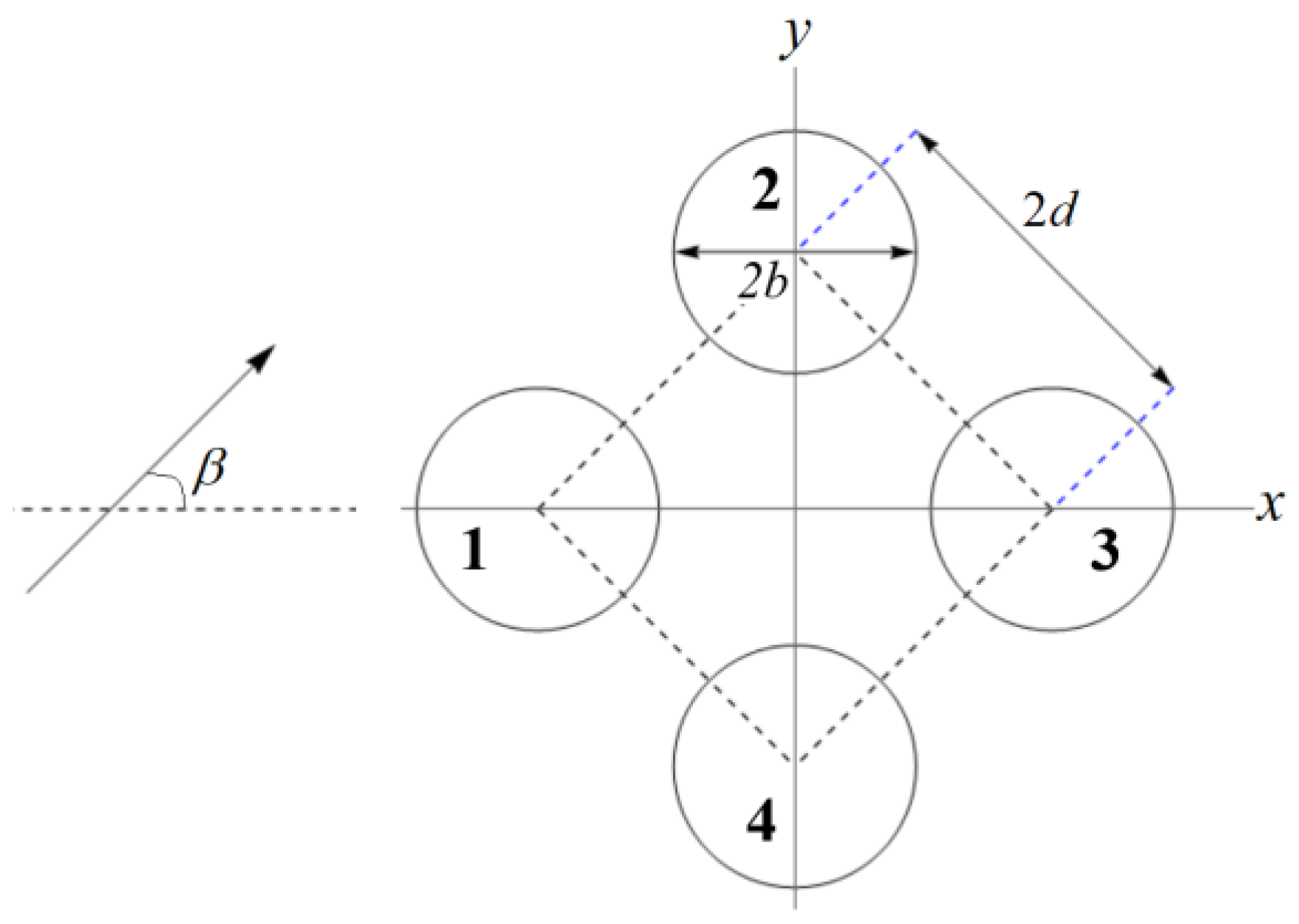
19]. The configuration considered is the four identical cylinders of radius
with centres
, and
, respectively. The distance between the centres of adjacent cylinders is
(see
Figure 2). The parameters
Pa,
are adopted for comparison purposes.
The relation between the incident wave amplitude
in (11) and the incident wave amplitude
in [
19] is given by
. The
- and
-components of the wave forces are non-dimensionalized by
for comparison purposes with Ren et al. [
19]. The non-dimensional forces are denoted by tilde,
and
In the subsequent Figures, the modulus of the non-dimensional force components
and
are presented for the cylinders given in
Figure 2. The ratio
incident wave direction
water depth
, and ice thickness
are adopted. Due to the position of the cylinders and the angle of wave incidence
- and
-component of wave forces on cylinders 2 and 4 are the same, and the
-component of the wave force acting on the cylinders 1 and 3 are zero due to the symmetry of the cylinder configuration. In
Figure 3, the present wave force results are compared with those by Ren et al. [
19], and the effect of the number of vertical modes retained is investigated. First, it is seen that the present results match quite well with those by Ren et al. [
19]. Second, it can be observed from
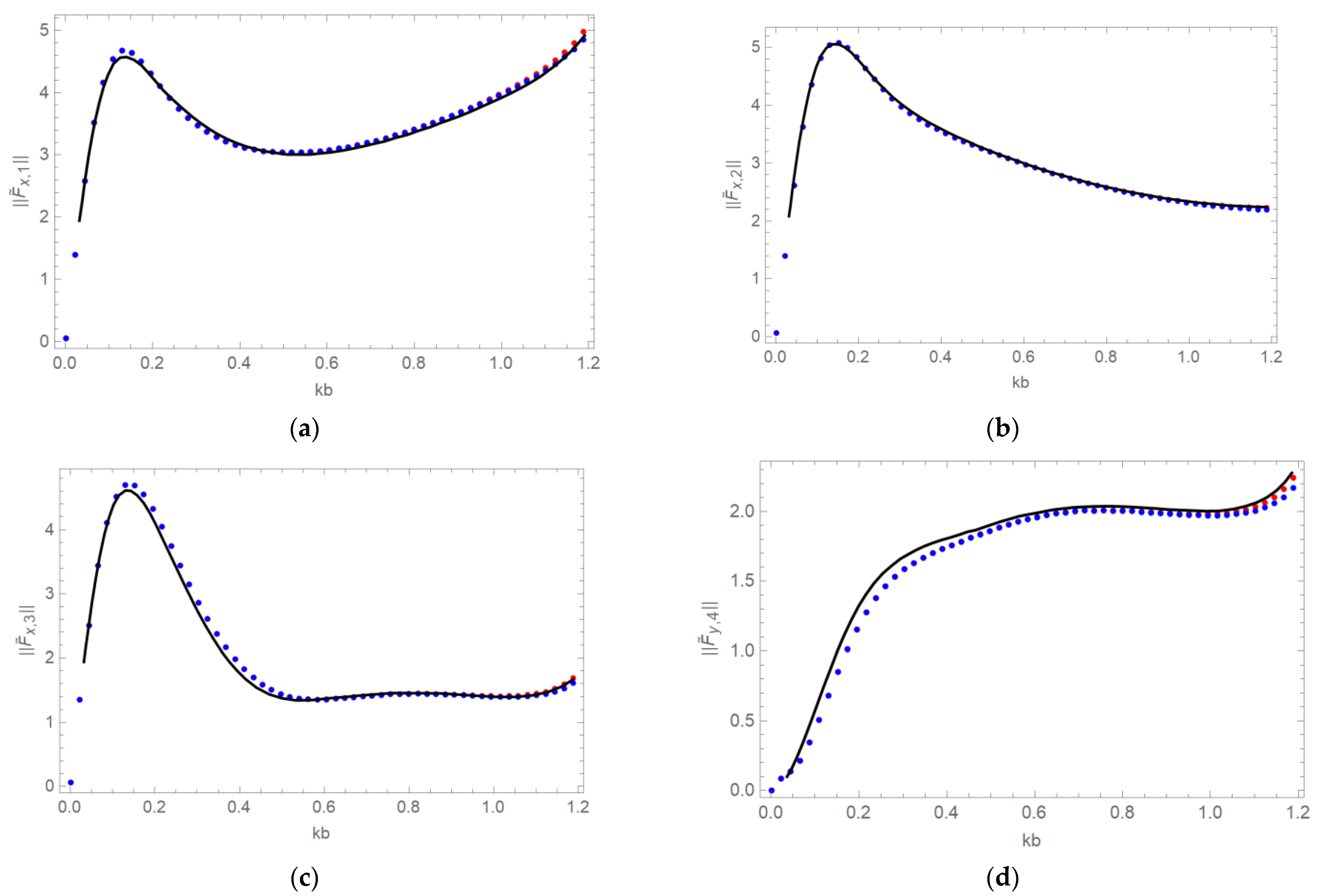
Figure 3 that, for the geometry considered here, it is sufficient to consider the vertical modes in (29) and (31) from
to 5 (taking only five evanescent modes). Increasing the number of evanescent modes to 10 does not make any difference, except for a small deviation in the high-frequency range. In the subsequent figures, the Fourier modes
in the series of the incident and diffracted wave potentials (20), (25), (29), and (31) are taken from −5 to 5. It is observed that increasing the number of Fourier modes does not change the numerical results.
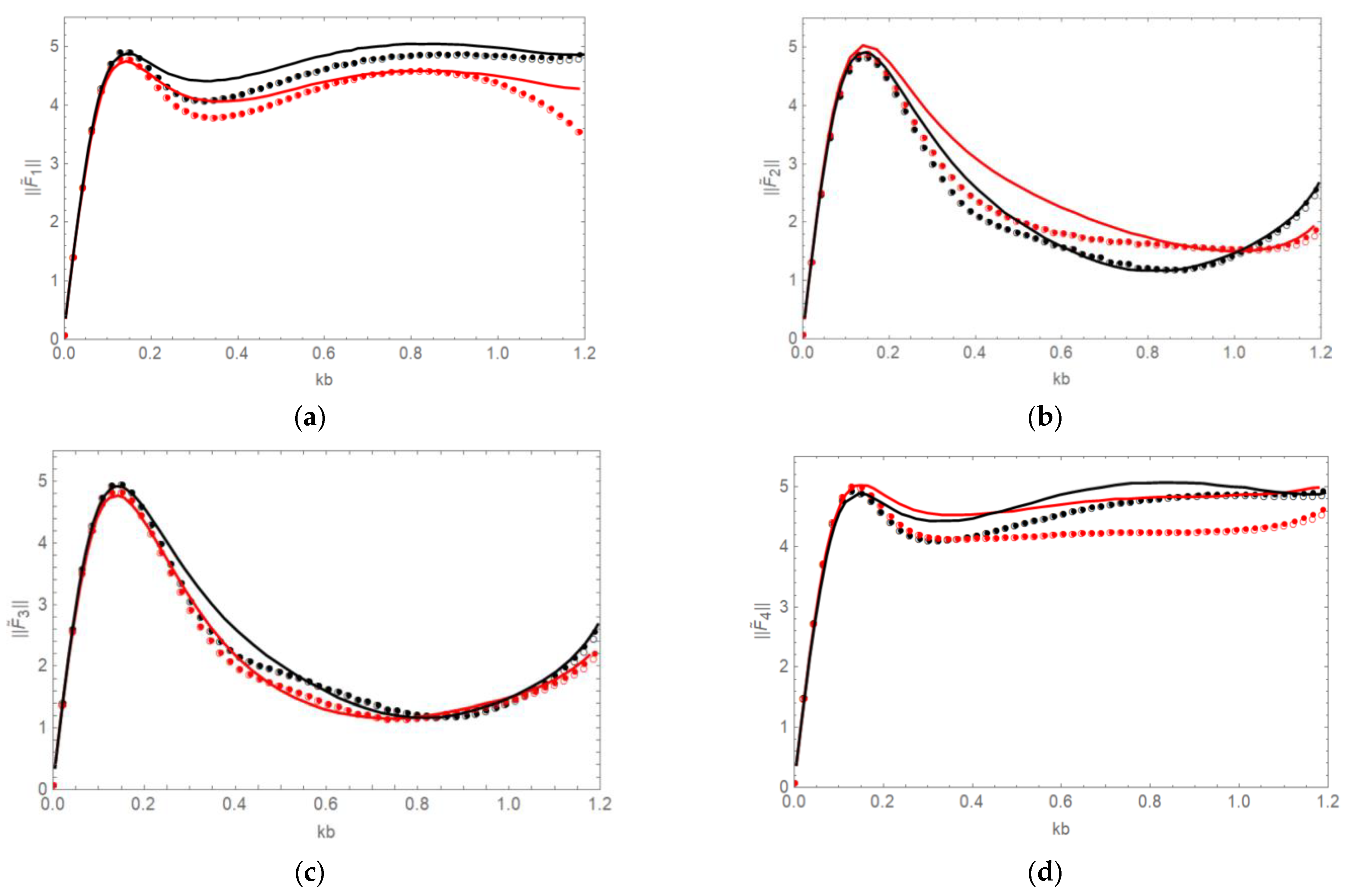
In
Figure 4, the effect of different incident wave angles,
and
on the wave forces is investigated for cylinder spacing
. The non-dimensional total wave forces
are compared with the results of Ren et al. [
19] for the cylinders given in
Figure 2. Wave forces are shown in red and black, corresponding to the incident wave angle
and
respectively. The solution by Ren et al. [
19] is shown by solid lines, and the present solution with five and ten evanescent modes is shown by empty and filled circles, respectively. It is seen from
Figure 4 that the difference between the filled and empty circles is nearly invisible, except for a very small deviation in the high-frequency range. As a result, five evanescent modes are determined to be sufficient to calculate the wave forces for non-zero incident wave angles, just as they are for zero incident wave angles. Total wave forces acting on cylinders 1, 4 and 2, 3 are the same for incident wave angle
due to the symmetry of the cylinder configuration (see
Figure 2). It is seen that present force results show similar behavior to the results of Ren et al. [
19].
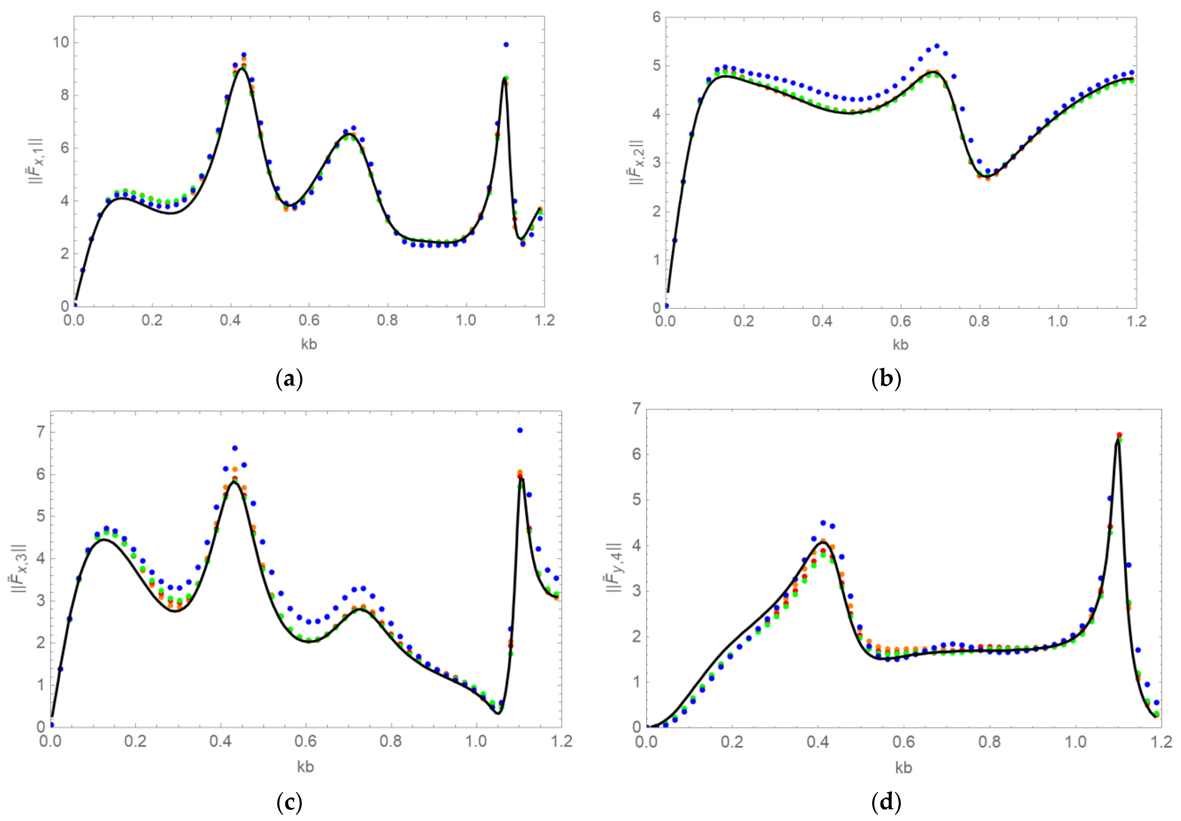
In
Figure 5, cylinder spacing is changed to
and the other parameters are kept the same as in
Figure 3. The effect of cylinder numbering in the present iteration method is investigated. For example, the cylinder numbering 1-2-3-4 is shown in
Figure 2. We start numbering the cylinders from the left-hand side and continue in the clockwise direction. Four different cases are investigated: cylinder numbering as 1-2-3-4 (red dots), 1-2-4-3 (green dots), 1-4-3-2 (orange dots), and 2-3-4-1 (blue dots). It is seen from
Figure 5 that cylinder numbering as 1-2-3-4 (red dots), 1-2-4-3 (green dots), and 1-4-3-2 (orange dots), where the iteration starts from the closest cylinder (cylinder 1) to the incident wave, gives closer wave force results to Ren et al. [
19] compared to the other case. The case where the iteration does not start from the closest cylinder to the incident wave–for example, the wave forces calculated by the cylinder numbering as 2-3-4-1 (blue dots)–shows similar behavior to the other cases but converges to different results than Ren et al. [
19]. This shows that for the configuration of the cylinders given in
Figure 2, the left-most cylinder should be numbered as cylinder 1. Choosing cylinder 1 as the closest cylinder to the incident wave and then numbering other cylinders arbitrarily for this configuration produces similar wave force results (see
Figure 5). However, if the cylinders are positioned in a single array, they should be numbered according to their relative position, with respect to the ambient incident wave direction: the closer the cylinder to the waves, the lower the number. Note that, in
Figure 5, wave forces for the cylinders are shown in the numbering system 1-2-3-4.
All calculations in this paper are carried out with twenty iterations, for which the convergence of the present iterative scheme is obtained. The problem (1)–(14) is also solved by using the iteration method of Twersky [
1]. In that iteration method, the wave potentials are calculated separately for each cylinder by using the data obtained in the previous iteration. The new iteration method developed in this paper uses the idea of the Gauss-Seidel iteration method for linear systems. The data obtained for a cylinder at the
-th iteration is used for the next cylinder at the same iteration. Thus, it is predicted that the present iterative method is faster than Twersky’s method. For example, for
with Twersky’s iteration method, 90 iterations are needed for convergency of the wave force acting on cylinder 1 in
Figure 2, but 20 iterations are enough with the present iteration method. For the configuration of the cylinders given in
Figure 2, the time needed to obtain the convergence with the present iterative method is six times less than that when using the Twersky’s method. In Twersky’s method, the cylinder numbering is not important, but that method converges more slowly than the present iterative method. For the convergency of the iteration method, we mean that the maximum relative error between two consecutive iterations for the wave force is small,
for each cylinder
where
is a small number,
counts the number of iterations and
is the interval for the non-dimensional wave number
Maximum relative error is smaller than
for the wave forces given in
Figure 5. There is no visible difference for the wave force results in
Figure 5 with 20 iterations and 40 iterations by the present iterative method.
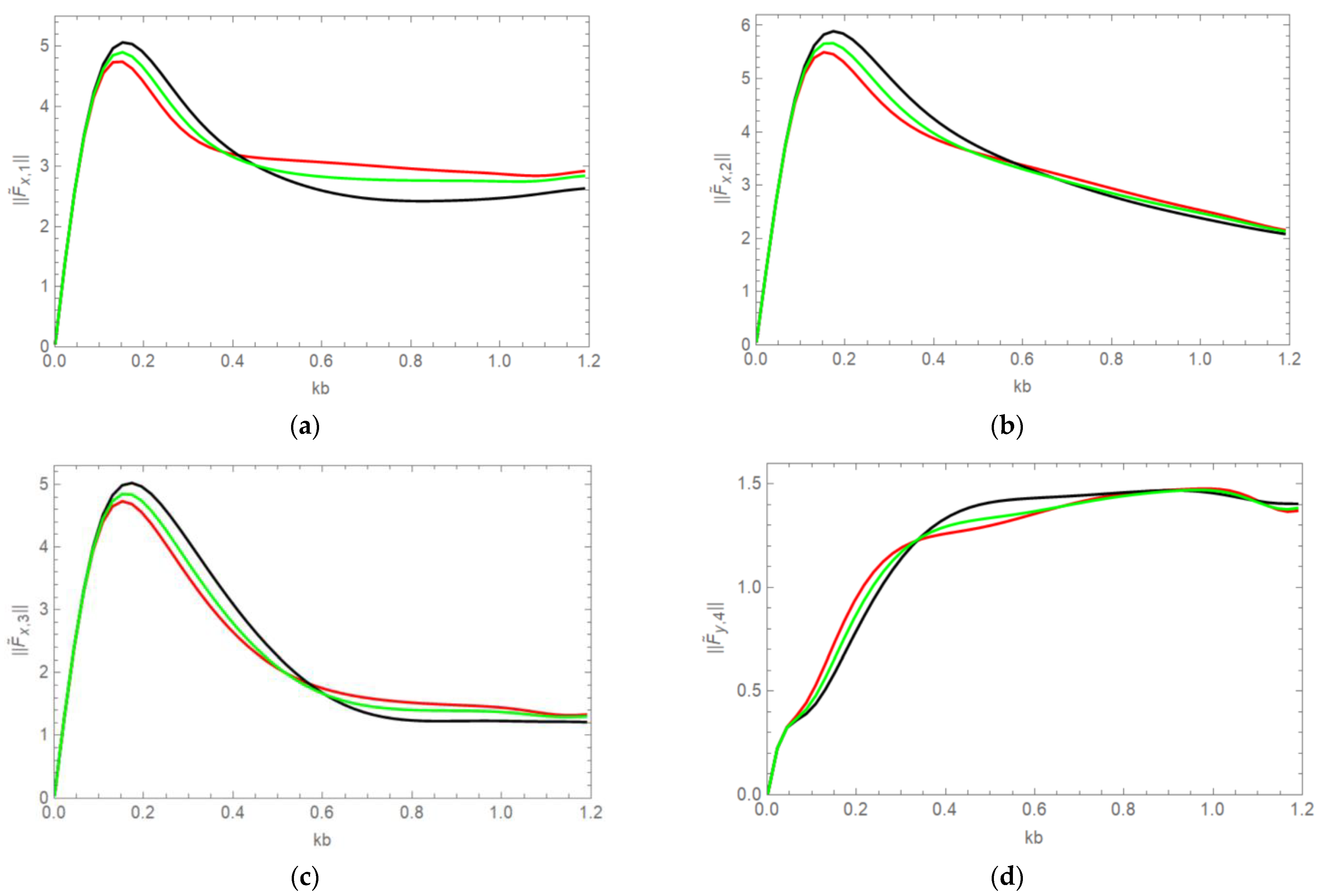
In
Figure 6, non-dimensional wave forces acting on the cylinders in
Figure 2 are presented for different ice thicknesses,
m (black line),
m (green line) and
m (red line). Here, the cylinder spacing is chosen as
. For small wave numbers the higher ice thickness results in smaller wave forces in the
-direction, but for large wavenumbers the higher ice thickness results in higher wave forces in the
-direction.
6. Conclusions
A new iteration method combined with the vertical mode method has been proposed and applied to the problem of hydro-elastic wave interaction with multiple vertical circular cylinders. The algorithm of the problem solving has been described and explained. Numerical calculations of the wave forces are reduced to operations with the Fourier coefficients of the velocity potential. Wave forces acting on four circular cylinders in a square arrangement have been calculated for different cylinder spacings, incident wave angles, and ice thicknesses. Good agreement is achieved with the results by Ren et al. [
19]. The present iteration method converges much faster than Twersky’s method [
1]. For the geometry considered in this paper, five evanescent modes are found to be sufficient to obtain good convergence.
The cylinders are rigid in the present analysis. In terms of marine structures frozen in ice, the structural flexibility, and the dynamic fluid–structure interaction are of practical interest. Such dynamic interactions have been studied for water waves, see [
22,
23,
24,
25], but not yet for hydro-elastic waves. For columns frozen in ice, their ability to deform is limited compared to the same columns in open water. The columns are supported (clamped) not only at the bottom but also along the contact line between the ice and the column. It is possible to model the column support at the contact line as an elastic support. Then, one needs to account for compression in ice cover, which makes the Bernoulli-Euler equation of a thin elastic plate (5) more complicated. The authors are unaware of any research in this field. The compression forces at the contact line could be large, leading to crushing the ice near the surface of the column.
Other conditions on the contact line can be considered. The free–free contact conditions were studied in [
18] for a single circular cylinder. Crushing of ice at the contact line was studied [
18], but the possibility of crushing was not allowed. There are also complicated but practically interesting problems, where a part of the contact line is clamped to the cylinder and another part is free of stresses and shear forces. The difficulty of such formulation is that the location of these parts is unknown in advance; they should be determined as part of the solution.
As a future work, the problem investigated in this paper is planned to be solved for free-edge conditions. In addition to that, the problem of many vertical cylinders with non-circular cross-sections is planned to be solved by the present method and by the direct matrix method.


