Abstract
Since the sideslip angle is often ignored or simplified in the process of path following of unmanned surface vehicle by using the line-of-sight (LOS) guidance law because of its fast change and the difficulty of measurement, an observer was proposed by internal model control (IMC) to quickly estimate the sideslip angle in the LOS guidance law. First, a prediction model was established for the tracking error, and a state space model for prediction errors was constructed as an internal model. With the introduction of the auxiliary variables, a new augmented system was set up for a state space model of the prediction errors. Then, the sideslip angle observer was designed by the theory of state feedback with the feature of the control law of a proportional-integral type. Theoretically, the stability of the system was proved based on the Lyapunov criteria. A simulation and experiment verified the effectiveness of the proposed sideslip angle observer in improving the path-following accuracy. The results show that the IMC-based observer introduces a proportional term of tracking error that is not considered by other observers, which is easier to implement and adjust, and has a faster response speed and a smaller steady-state error for the sideslip angle. In addition, the assumption of a small sideslip angle is not introduced in the design process, so the proposed observer provides an accurate estimation method for a large sideslip angle.
1. Introduction
Unmanned surface vehicles (USV) are widely used in military and civil applications due to their small size, low cost, and maneuverability [1]. To accomplish the missions accurately, high-accuracy USV path following is indispensable. The path following includes a guidance algorithm, heading controller, speed controller, etc. The guidance algorithm is the basis for the USV to achieve path following. It guides the USV to follow the desired path in time according to the relative motion of the USV and the desired path, so that the USV can follow the desired path quickly and accurately. At present, there are many guidance algorithms, such as the vector field guidance, which establishes a vector field on the desired path and continuously guides the USV to turn to the optimal direction calculated by the vector field [2,3], as well as the “follow-the-carrot” approach [4], which sets virtual points on the desired path and completes the path following by chasing the virtual points. Those methods are more complicated to apply, while Line-Of-Sight (LOS) has the advantage of being more intuitive and easier to implement by imitating the helmsman’s action to guide the USV to steer in the “line of sight” direction from the current position to the target point.
Since a USV does not have lateral thrust during navigation, it is susceptible to the influence of its structure and the disturbance of the external environment, resulting in a sideslip angle [5]. The influence of the sideslip angle is not considered in the traditional LOS algorithm, so that there is always a deviation of the sideslip angle between the desired heading direction and the actual desired heading direction, which reduces the path-following accuracy. Therefore, compensating for the sideslip angle is an important research point to improve path-following accuracy.
To compensate for the sideslip angle, various advanced LOS algorithms have been proposed, such as integral LOS (ILOS) [6,7,8,9] and adaptive LOS (ALOS) [10,11,12,13,14]. ILOS introduces an integration term into the traditional LOS, which contains the cross error and the lookahead distance. The presence of a sideslip angle results in a cross error, leading to the continuous accumulation of this integration term, which generates an angle used to compensate for and mitigate the effects caused by the sideslip angle. ALOS treats the sideslip angle as an unknown constant parameter and designs an adaptive term that can be estimated in real time based on the cross error and speed, ensuring that the obtained sideslip angle converges exponentially to the actual value.
On the other hand, the observer can estimate the system state in real time. In [15], considering the sideslip angle as an unknown parameter, an LOS based on a reduced-order extended state observer was proposed to achieve real-time estimation of the sideslip angle in the small angle case. In [16], a high-gain extended state observer was used to obtain the time-varying sideslip angle to compensate for external disturbances and achieve accurate path following of a USV in restricted waters. Reference [17] obtained the longitudinal and lateral velocities of the USV through a high-gain observer to indirectly estimate the sideslip angle to compensate for the model uncertainty and unknown external disturbances. In [18], a finite-time sideslip observer was proposed to accurately estimate the time-varying large sideslip angle in finite time, which improved the speed and accuracy of path following. In [19], under the condition that the sideslip angle was small (assuming sin β ≈ β), a monomial containing the prediction error was introduced into the path-tracking error system, a predictor was constructed for predicting the along and cross error of path following, and based on this, a Lyapunov function was constructed to design the sideslip angle observer to achieve the estimation of and compensation for the sideslip angle. In [20], a finite-time predictor-based LOS (FPLOS) algorithm was proposed. Based on [19], it introduced the ρ power function of the prediction error with sign function to construct the observer and realized the estimation of and compensation for the sideslip angle in finite time. However, the FPLOS algorithm used a pure integral observer suitable for small-angle sideslip angle estimation and responded slowly to large angle sideslip angle estimation. In actual navigation, a USV is affected by the channel curvature, current, wind, and waves, which may generate a large sideslip angle, and FPLOS is not able to cope with this. Therefore, it is very important to explore the advanced control method to design the sideslip observer under the condition of unlimited small angle sideslip to solve the problem of fast estimation of the sideslip angle; it is also an effective method to improve the USV path-following accuracy.
The internal model control (IMC) has been widely used for its advantages of strong practicability, intuitive design, and easy adjustment [21,22]. In [21], an adaptive IMC that allowed parameter adjustment and model estimation was proposed to achieve autonomous landing control of a fixed-wing UAV under different wind conditions. In [22], an IMC-based PID controller was proposed for the magnetic levitation system, which improved the transient response and tracking response of the magnetic levitation system. In this paper, an IMC observer-based sideslip angle estimation method is proposed to improve the LOS algorithm (IMCLOS) to achieve fast and accurate USV path tracking. First, a prediction model is established to predict the along and cross error of path following, and the internal mode extended state equations for predicting the along and cross error are constructed. The control law of the observer is designed based on the IMC principle, which is a proportional-integral controller, and the stability of the IMC observer is proved by designing the Lyapunov function. Compared with the FPLOS algorithm, the IMCLOS algorithm is easier to implement and regulate, due to the introduction of the proportional integral of the tracking error in the observer, and has a faster response and smaller steady state error for the sideslip angle observation in the LOS algorithm.
The rest of the paper is organized as follows: Section 2 introduces the USV dynamic model, including kinematics and kinetics. Section 3 mainly introduces the design of the sideslip angle observer based on the IMC and analyzes the stability of the system based on the observer. In Section 4, the effectiveness of the observer is proved by simulation and field experiment. Finally, Section 5 presents conclusions and future work.
2. USV Dynamic Model
In order to design and validate the sideslip angle observer, a mathematical model of the USV is required. Therefore, this section presents the dynamics model of the USV.
2.1. Assumptions
A USV has six degrees of freedom motion in navigation, including surge, sway, heave, yaw, roll, and pitch, but when the USV is controlled for path following, heave, roll, and pitch have little effect on it. Therefore, some simplifications are made to its motion in the horizontal plane. These are simplified as follows:
- We ignore the USV motion in the roll, pitch, and heave directions;
- The USV is a symmetric structure, and its center of mass and the origin of the body-fixed coordinate coincide;
- We ignore the propeller thrust model and directly adopt forward thrust and turning moment as the control inputs.
2.2. USV Plane Motion Model
A USV path following plane diagram is shown in Figure 1, where x, y, and ψ are USV’s northward position, eastward position, and heading angle of the USV in the northeast coordinate system, respectively; u, v, and r are the surge speed, sway speed, and yaw speed of the USV in the hull coordinate system, L(θ) is the reference path, and θ is the path parameterization variable.
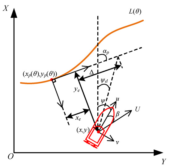
Figure 1.
USV path following plan.
The mathematical model of the motion of the USV in the horizontal plane is
Equation (1) contains the kinematic and kinetic equations of the USV, where η = [x y ψ]T is the attitude vector, v = [u v r]T is the velocity vector, J(ψ) = [cosψ − sinψ 0; sinψ cosψ 0; 0 0 1] is the coordinate transformation matrix from the USV’s hull coordinate system to the north-east coordinate system; M = [m11 0 0; 0 m22 0; 0 0 m33] is the fluid inertia matrix, where , , , m is the mass of USV, Izz is the inertia of the USV mass during steering, is the longitudinal added mass, is the lateral additional mass, is the additional mass generated during steering; C(v) = [0 0 c13; 0 0 c23; c13 − c23 0] is the fluid Coriolis force matrix, where c13 = −c31 = −(v + 0.5)m22, c23= −c32=m11u; D(v) = [d11 0 0; 0 d22 d23; 0 d32 d33] is the fluid damping matrix, where d11 = −Xu − X|u|u|u|, d22 = −Yv − Y|v|v|v|, d23 = −Yr, d32 = −Nv, d33 = −Nr − N|v|r|v|, and Xu, Yv, Yr, Nv, Nr is the hydrodynamic coefficient, X|u|u, Y|v|v, Y|r|r, N|v|v, N|v|r is the nonlinear damping factor; τ = [τu 0 τr]T is the matrix of control forces generated by the actuator, where τu is the longitudinal thrust, τr is the bow torque; and δd = [δdu δdv δdr]T is the disturbance of surge speed, sway speed, and yaw speed by factors such as wind and current.
As seen in Figure 1, a USV navigating along the path L(θ) needs to have a path following technique, which consists of heading control, speed control, and an LOS guiding law. In this paper, we focus on an LOS algorithm regarding the sideslip angle compensation.
3. LOS Algorithm Based on Sideslip Angle Compensation
3.1. Basic Principle of LOS Algorithm
LOS is widely used for path following control. The main reason is that LOS can be independent of the dynamics model of the USV and does not depend on the mathematical model of the system; its output is the desired heading angle, which is determined by the real-time position of the USV and the reference path. The idea of LOS is to imitate the helmsman’s action, keep the heading angle of the USV aligned with the desired heading angle, and control the USV to reach the desired position to achieve path following. Figure 1 gives the geometric principle of an LOS-based USV path following, where (xp(θ), yp(θ)) is the projection point of the USV on the reference path, xe and ye are the along and cross error of the path following, Δ is the lookahead distance, β is the sideslip angle, which is the angle between the USV resultant velocity U and the surge velocity u, and αp = arctan(x′p(θ)/y′p(θ)) is the angle between the tangent line at the projection point and the vertical coordinate, ψd is the desired heading angle, and the LOS algorithm is
where β affects the value of ψd. In the application of the LOS algorithm, because the β value is not easy to measure, the influence of β on ψd is usually ignored [23,24]. As a result, the LOS is prone to produce a large tracking error under the influence of channel curvature, water flow, wind waves, and other factors; an FPLOS algorithm designed the observer to estimate the sideslip angle and compensate for the ψd value, thus improving the path following accuracy of a USV [20]. On the condition that the β value is very small, an observer with a tracking error integral was designed. Therefore, it is very important to explore the advanced design method of an observer and realize the fast and accurate estimation of the sideslip angle.
3.2. Sideslip Angle Observer Based on IMC
3.2.1. Path-Following Error Dynamic System
In the design of the sideslip angle observer, the output of the dynamic system of the USV path-tracking error is usually taken as the input [18,19,20]. According to (1), the along error and cross error of USV path following are
We derive the along error xe and cross error ye of path tracking with respect to time:
where up and are
where up is the virtual input used to stabilize the along error xe, which will be designed later. According to (6), can be calculated according to up. The FPLOS algorithm assumes that β is a small angle, then sinβ ≈ β, cosβ ≈ 1. By substituting into (4), the dynamic system of tracking error can be obtained as = Ucos(ψ − αp) − Usin(ψ − αp)β + − up, = Usin(ψ − αp) + Ucos(ψ − αp)β − . FPLOS derived from this condition limits its application scope and can only be applied to the estimation of a sideslip angle at a small angle [20]. IMCLOS does not limit the value of β and can be applied to any value of β.
Let the parameters βx and βy be
Equation (7) can be substituted into (4) then
Equation (8) is the error state equation of USV path following, and then the IMC observer is proposed.
3.2.2. IMC Observer Design
Since there are coupling components in (8), the prediction model of along error xe and cross error ye is defined as
where kx and ky are positive constants, is the estimation of xe, is the estimation of ye, and are prediction errors, and and are estimations of βx and βy.
Subtract (8) from (9), then
where
where and are prediction errors. According to (10), the differential term is eliminated, so this term has no influence on the estimation effect of the final observer. Meanwhile, it can be seen that the convergence rate of the prediction error is positively correlated with the values of kx and ky, which will affect the estimation effect of the observer.
According to (10), there is no mutual coupling factor between the equations of state, and the observer can be designed independently. Equation (10) provides a new equation of state for by
Assuming zero reference input, in (12) is regarded as the control quantity to be designed. The tracking error e is defined as
By introducing two new state variables z and w, it can be obtained as follows
Equations (13) and (14) constitute the new augmented system equation as follows
where A = [0 −1; 0 −kx], and B = [0 U]T. According to (15), the rank of the controllability matrix of the system is rank [B AB] = 2, and system Equation (15) is completely controllable. According to the principle of state feedback, the system can be controlled by state feedback. Let w = KX and K = [k1 k2]; so, the controlled system (15) can realize asymptotic stability, and the control quantity w can be obtained from (13) and (14) as follows
Similarly, a control law can be designed for the observer of by
In order to make the closed-loop system formed by feedback of (15) asymptotically stable, that is, the eigenvalues of A − BK all have negative real roots, then
At the same time, φp = ψ − αp + β is unchanged in a sampling period of the control system, that is, . This gives us the derivative of (11) as follows
Substituting (16) and (17) into (19), it can be obtained as follows
It can be seen from (20) that the control law of IMC observer is composed of a proportional term and integral term about the tracking error, while the observer designed in reference [20] is in pure integral form. Therefore, IMCLOS has a faster response speed and a smaller steady-state error to the sideslip angle. On the other hand, the values of k1 and k2 are related to the prediction error, and the excessively large values of kx and ky in (10) will cause the prediction error to fluctuate in a small range. In order to accurately predict the sideslip angle, large values of k1 and k2 are required, but the control law contains the proportion term, which will cause the sensor measurement error to be amplified. Therefore, the values of kx and ky should not be too large.
According to (7) and (20), the estimation of the sideslip angle is
To stabilize the along error xe, up in (4) is designed as
The predicted sideslip angle obtained in (21) is substituted for the actual sideslip angle β in (2) to complete the design of IMCLOS algorithm.
3.3. Stability Analysis of IMC Observer
The IMC observer is
According to (8), (9), and (23), the prediction error dynamic system is
It is assumed that the speed controller and heading controller can achieve the control target without steady error, i.e., U = Ud and ψ = ψd. Based on this assumption, we assign the following Lyapunov function candidate V(x) as
where , b = k2U, c = U, , and the matrix P is
According to the Hurwitz criterion, Δ1 > 0, Δ2 > 0, Δ3 > 0, and Δ4 > 0; then, the matrix P is a positive definite matrix, i.e., V(x) > 0.
The derivative of (25) is
Substituting (18) into (27), can be obtained, so the IMC observer (23) is asymptotically stable. Since the design of the controller is not the focus of this paper, we have chosen the more widely used PI controller. The proof is based on the assumption that the controller part is stable; then, the stability of the whole closed-loop system is proved.
4. Simulation and Experiment
4.1. Sideslip Angle Observer Based on IMC
Figure 2 shows the USV experimental platform, which consists of six modules: USV hull, navigation controller, RC receiver, electronic speed controller (ESC)+ brushless motor, GNSS positioning module, and data transmission module, where the USV hull is 1.18 m long, 0.355 m wide, and weighs 8.46 kg, and the USV-related kinetic parameters are given in Table 1, obtained by experimental tests. The navigation controller model is V5+ with a built-in accelerometer, gyroscope, electronic compass, and barometer, which can obtain real-time speed, acceleration, and a heading angle of the USV at 50 Hz; the model of the GNSS positioning module is a NEO V2 with a sampling frequency of 10 Hz; the USV is propelled by dual brushless motors with differential steering, and the motor model is CYS3660 with maximum power of 1800 W.
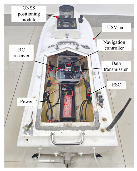
Figure 2.
USV experimental platform.

Table 1.
USV-related kinetic parameters.
In the simulation and outfield experiments, the path following control system shown in Figure 3 was used, and (9) and (20) constituted the observer about . Similarly, the value of can be obtained. The estimation of the sideslip angle was obtained from (21). The speed was controlled by PI, the input was the expected speed Ud, and the real-time speed measured by the sensor was the feedback state. Its parameters were kp = 1.0 and ki = 0.4. The heading was controlled by PI. The expected heading angle obtained by the LOS algorithm was used as the input of the heading controller, and the real-time heading angle measured by the sensor was used as the feedback state. The heading controller parameters were kp = 0.5 and ki = 0.2. The parameters of the IMCLOS algorithm were set to kx = 10, ky = 10, ku = 3, ∆ = 1, k1 = 100, and k2 = 50. To verify the merits of the IMCLOS algorithm, a comparison was made with the FPLOS algorithm. The parameters of the FPLOS algorithm were set to kx = 10, ky = 10, ku = 3, ∆ = 1, k1 = 100, and ρ = 0.8, where ρ was set to the same value as in [20]. As the USV is following the path, it is likely to produce a large sideslip angle due to the great curvature change of the path and external interference. Therefore, it was necessary to set a path with a large curvature and analyze the effect of the observer in IMCLOS and FPLOS by the results. We set the desired path following speed to 0.5 m/s and the reference path L(θ) as
where θ ∈ [0,+∞).
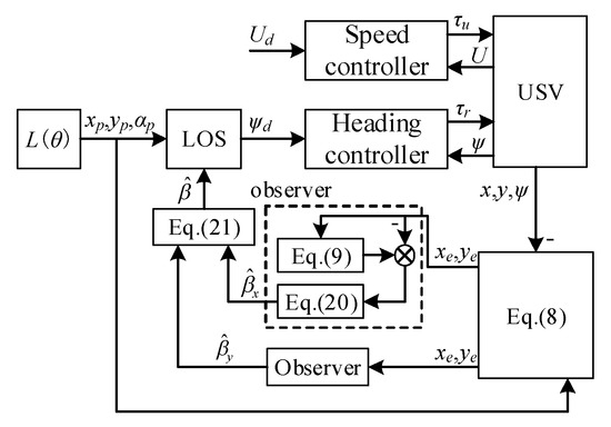
Figure 3.
Block diagram of the IMCLOS-based path following system.
4.2. Simulation Verification
In the Matlab simulation environment, the path following control simulation model was established, the following range was set to θ∈ [0, 28), the initial speed was set to 0 m/s, the initial heading was 0 rad, and the desired speed was 0.5 m/s. Because the USV used in the experiments was similar in size and mass to the USV used in the experiments of [20], referring to [20], the disturbance quantities δdu = 0.3 sin(0.1πt − 0.2π), δdv = 0.2 cos(0.5πt + 0.1π), and δdr = 0.3 cos(0.2πt + 0.1π) were added artificially. Under the action of the same speed controller and heading angle controller, Figure 4 shows the heading angle tracking error eψ for the USV path following process, which was eψ = ψd − ψ obtained respectively from IMCLOS and FPLOS. Figure 5 shows the actual USV sideslip angle β, the estimated sideslip angle , and the sideslip error value obtained by the compensation of the two observers. Figure 6 shows the USV following trajectory based on the two observers, and Figure 7 shows the along error xe and the cross error ye in the USV path following process.
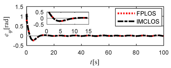
Figure 4.
Heading tracking error eψ.
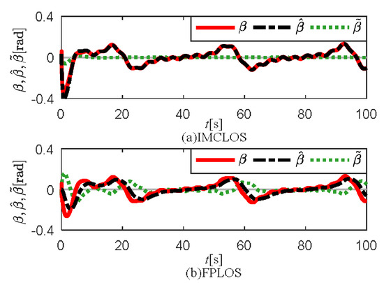
Figure 5.
from IMCLOS and FPLOS.
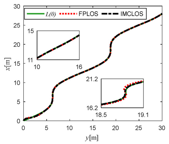
Figure 6.
Path following simulation results.
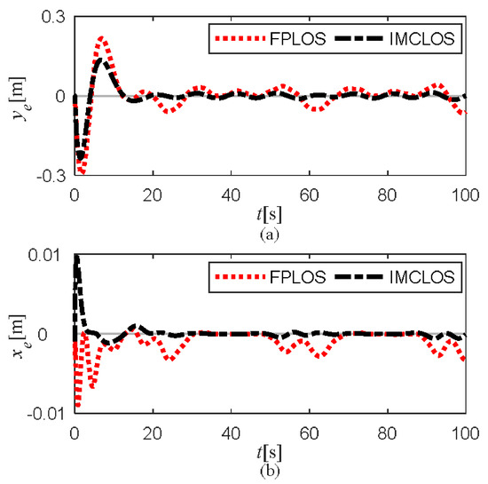
Figure 7.
xe (b) and ye (a) from IMCLOS and FPLOS.
As seen in Figure 4, the USV entered the stable tracking state after about 10 s. Compared with Figure 5, it can be seen that when the sideslip angle β was small (30 s < t < 50 s and 70 s < t <90 s), both observers achieved an accurate estimation, which as reflected in Figure 6 was the interval of tending to a straight-line path tracking (10 m < x < 15 m, 8 m < y < 18 m; 22 m < x < 28 m, 20 m < y < 30 m). When the sideslip angle β was large (10 s < t < 30 s and 50 s < t < 70 s), the IMCLOS algorithm still accurately estimated the actual sideslip angle β in real time with a maximum prediction error of about ±0.002 rad. The FPLOS algorithm estimates lagged behind the actual sideslip angle, indicating that the response of FPLOS was slow, resulting in a large estimation error with a maximum prediction error of about ±0.08 rad. Examining the path-tracking effect in Figure 6 for the path turn, IMCLOS had a higher prediction accuracy for the sideslip angle, and its trajectory was closer to the reference path compared to FPLOS. The path-tracking errors are shown in Figure 7. Comparing the along and cross errors, both of these with IMCLOS were smaller than with FPLOS, and the advantage was more obvious in the large sideslip angle interval. The maximum value of the cross error ye obtained by the IMCLOS algorithm was about 0.02 m, compared with 0.06 m obtained by FPLOS; Similarly, the along error xe obtained by IMCLOS compensation was about 33% of that obtained by FPLOS. Therefore, the simulation results show that IMCLOS maintained the performance of real-time estimation of a small sideslip angle, while being able to estimate a large sideslip angle and achieve accurate following of the reference path quickly and accurately.
4.3. Experimental Comparison
In the USV experimental platform, the control algorithm was implemented by modifying the flight control firmware ArduPilot (copyright by ArduPilot Dev Team). ArduPilot mainly contains five parts: a vehicle code, shared libraries, a hardware abstraction layer, tools libraries, and an external support code. Based on this, a new operating mode-LOS_Mode was added to the vehicle code, in which library functions were called to obtain the real-time position, speed, and heading angle measured by the USV sensors, and the control algorithms based on IMCLOS and FPLOS were programmed in C++ to output the desired heading angle command and call the motor control functions to realize the USV heading and speed control during the path-following process. After finishing the navigation, the ground station MissionPlanner was used to read the navigation log, and Matlab was used to analyze the data generated in the first 100 s and plot the curve. The flow chart of the algorithm implementation in the USV platform is shown in Figure 8. Figure 9 shows the heading angle tracking error eψ for the USV path-following process. Figure 10 shows the estimated USV sideslip angle obtained by the two observers. Figure 11; Figure 12 show the USV following trajectory displayed in the ground station, where the solid line is the actual trajectory, and the dashed line is the reference path. Figure 13 shows the USV following trajectory plotted from the ground station derived data, and Figure 14 shows the along error xe and cross error ye in the USV path-following process.
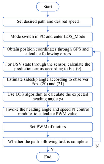
Figure 8.
Flow chart of algorithm implementation in the USV platform.
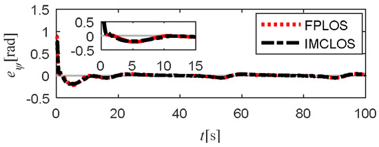
Figure 9.
Heading tracking error eψ.
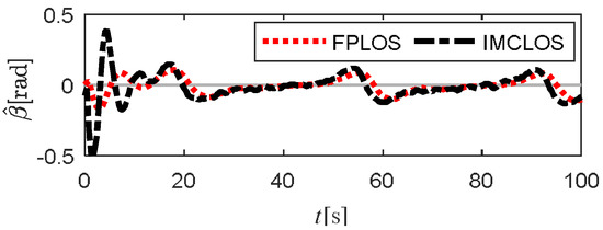
Figure 10.
from IMCLOS and FPLOS.
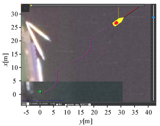
Figure 11.
Ardupilot path based on IMCLOS.
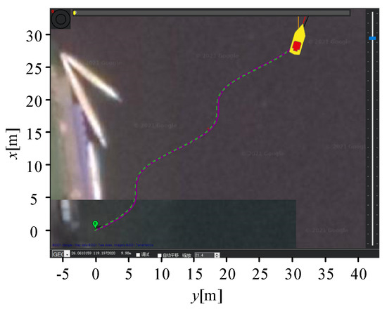
Figure 12.
Ardupilot path based on FPLOS.
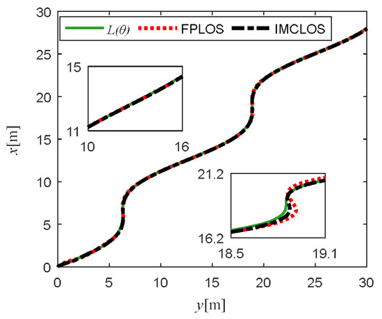
Figure 13.
Path-following comparison.
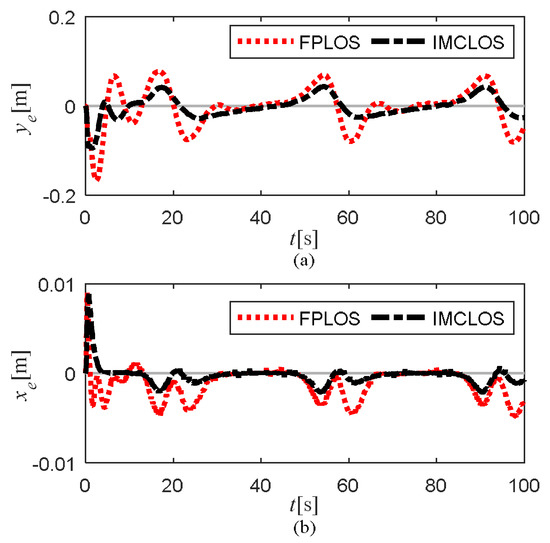
Figure 14.
xe (b) and ye (a) from IMCLOS and FPLOS.
Figure 8 shows that the USV entered the stable tracking state after about 10 s. During the stable tracking phase, comparing Figure 10, the estimation results of IMCLOS and FPLOS were more similar when the sideslip angle β was small (30 s < t < 50 s and 70 s < t < 90 s), which are reflected in Figure 10, Figure 11 and Figure 12; the interval of tending to a straight-line path following (10 m < x < 15 m, 8 m < y < 18 m; 22 m < x < 28 m, 20 m < y < 30 m) and the following effects were similar. For a larger sideslip angle β (10 s < t < 30 s and 50 s < t < 70 s), the estimation results of the two observers differed more, which are reflected in the path-following effect in Figure 11, Figure 12 and Figure 13 for the path turns. The IMCLOS-based trajectory was closer to the reference path, compared to FPLOS. Combined with Figure 14, the maximum cross error ye after the IMCLOS-estimated compensation was about 0.04 m, which was smaller than the 0.08 m obtained by FPLOS. Similarly, the along error xe obtained by IMCLOS compensation was about 50% of that obtained by FPLOS. The outfield experiments show that more accurate path following can be achieved by using IMCLOS estimation to compensate for the sideslip angle compared to FPLOS.
Both the experimental and simulation results show that IMCLOS had a better observation compensation effect on the sideslip angle than FPLOS, which could not only maintain the performance of real-time estimation of small sideslip angle but could also estimate a large sideslip angle quickly and accurately, and it obtained a faster response performance and smaller tracking error to achieve better path following.
5. Conclusions
In actual navigation, the sideslip angle of a USV changes rapidly and is difficult to measure. The LOS guidance algorithm often ignores or simplifies the effect of sideslip angle on the heading angle, which will reduce the path-following accuracy. In this paper, we proposed an IMC-based sideslip angle observer to achieve fast and accurate estimation of the sideslip angle to compensate with the LOS algorithm and achieve fast and accurate USV path following. Firstly, the prediction model of the tangential error and normal error was established, and the internal model extended state equation of the tangential error and normal error was constructed by using the IMC principle. Then, a new augmented system was obtained by introducing intermediate variables, and the stabilization of the system was realized by using the pole assignment method. At the same time, the stability of the designed system was proved by constructing Lyapunov function. The simulation results and the external experimental results both showed that
- (1)
- FPLOS was a pure integral type observer, while IMCLOS was a proportional integral type observer, which theoretically had better observer performance;
- (2)
- IMCLOS estimated β values faster and more accurately, especially the large-angle β value. In experiments, more accurate estimates of the sideslip angle reduced tracking errors by 50%, with more obvious advantages.
In future research, the influence of the sensor measurement error should be considered, and it is necessary to use multisensor fusion for data optimization. At the same time, obstacles and automatic collision avoidance should be considered in path following. Since the USV used was dual-propeller propulsion, a propeller thrust model should be considered and a model-based controller designed to improve tracking accuracy.
Author Contributions
Conceptualization, Y.H. and X.S.; methodology, Y.H.; software, X.S.; validation, Y.H. and X.S.; formal analysis, X.S.; investigation, X.S.; writing—original draft preparation, X.S.; writing—review and editing, Y.H. and X.S.; supervision, Y.H.; project administration, W.H. and S.C. All authors have read and agreed to the published version of the manuscript.
Funding
This research was funded by the National Natural Science Foundation of China: 51977040; Guide Project of Fujian Province: 2019H0007.
Institutional Review Board Statement
Not applicable.
Informed Consent Statement
Not applicable.
Data Availability Statement
Not applicable.
Conflicts of Interest
The authors declare no conflict of interest.
References
- Zhang, W.; Liu, X.; Han, P. Progress and challenges of overwater unmanned systems. Acta Autom. Sin. 2020, 46, 847–857. [Google Scholar]
- Xu, H.; Guedes, S. Vector field path following for surface marine vessel and parameter identification based on LS-SVM. Ocean Eng. 2016, 113, 151–161. [Google Scholar] [CrossRef]
- Sujit, P.; Srikanth, S.; Joao, B. Unmanned aerial vehicle path following: A survey and analysis of algorithms for fixed-wing unmanned aerial vehicles. IEEE Control Syst. Mag. 2014, 34, 42–59. [Google Scholar]
- Jooho, L.; Nakwan, K. Backward path following using pure pursuit guidance and nonlinear guidance for UUV under strong current. J. Ocean Eng. Technol. 2016, 113, 32–43. [Google Scholar]
- Wang, Y.; Tong, H. LOS guidance law for path following of hovercrafts with sideslip compensation. J. Harbin Eng. Univ. 2021, 113, 851–858. [Google Scholar]
- Li, L.; Dong, K.; Guo, G. Finite-time cooperative path following of surface vessels with surge velocity and yaw angle constraints. Control Decis. 2021, 36, 363–370. [Google Scholar]
- Liu, L.; Wang, D.; Zhou, H. Path following of marine surface vehicles with dynamical uncertainty and time-varying ocean disturbances. Neurocomputing 2016, 173, 799–808. [Google Scholar] [CrossRef]
- Wan, L.; Su, Y.; Zhang, H. An improved integral light-of-sight guidance law for path following of unmanned surface vehicles. Ocean Eng. 2020, 205, 107302. [Google Scholar] [CrossRef]
- Mu, D.; Wang, G.; Fan, Y. A time-varying lookahead distance of ILOS path following for unmanned surface vehicle. J. Ocean Eng. Technol. 2020, 15, 2267–2278. [Google Scholar] [CrossRef]
- Mu, D.; Wang, G.; Fan, Y.; Sun, X.; Qiu, B. Adaptive lOS path following for a podded propulsion unmanned surface vehicle with uncertainty of model and actuator saturation. Appl. Sci. 2017, 7, 1232. [Google Scholar] [CrossRef]
- Zheng, Z.; Zou, Y. Adaptive integral LOS path following for an unmanned airship with uncertainties based on robust RBFNN backstepping. ISA Trans. 2016, 65, 210–219. [Google Scholar] [CrossRef] [PubMed]
- Fossen, T.; Pettersen, K.; Galeazzi, R. Line-of-sight path following for dubins paths with adaptive sideslip compensation of drift forces. IEEE Trans. Control Syst. Technol. 2015, 23, 820–827. [Google Scholar] [CrossRef]
- Mu, D.; Wang, G.; Yun, S. Fuzzy-based optimal adaptive line-of-sight path following for underactuated unmanned surface vehicle with uncertainties and time-varying disturbances. Math. Probl. Eng. 2018, 6, 1–12. [Google Scholar] [CrossRef]
- Liu, F.; Yue, S. Drift angle compensation-based adaptive line-of-sight path following for autonomous underwater vehicle. Appl. Ocean Res. 2019, 93, 101943. [Google Scholar] [CrossRef]
- Liu, L.; Wang, D.; Zhou, H. ESO-based line-of-sight guidance law for path following of underactuated marine surface vehicles with exact sideslip compensation. IEEE J. Ocean. Eng. 2017, 42, 477–487. [Google Scholar] [CrossRef]
- Wang, J.; Zou, Z.; Wang, T. High-gain extended state observer based adaptive sliding mode path following control for an underactuated vessel sailing in restricted waters. Appl. Sci. 2019, 9, 1102. [Google Scholar] [CrossRef]
- Wang, Y.; Tong, H.; Wang, C. High-gain observer-based line-of-sight guidance for adaptive neural path following control of underactuated marine surface vessels. IEEE Access 2019, 7, 88–101. [Google Scholar] [CrossRef]
- Wang, N. Finite-time sideslip observer-based adaptive fuzzy path-following control of underactuated marine vehicles with time-varying large sideslip. Int. J. Fuzzy Syst. 2018, 20, 1767–1778. [Google Scholar] [CrossRef]
- Liu, L. Predictor-based LOS guidance law for path following of underactuated marine surface vehicles with sideslip compensation. Ocean Eng. 2016, 124, 340–348. [Google Scholar] [CrossRef]
- Yu, Y.; Chen, G.; Yu, H. Finite-time PLOS-based integral sliding-mode adaptive neural path following for unmanned surface vessels with unknown dynamics and disturbances. IEEE Trans. Autom. Sci. Eng. 2019, 16, 1500–1511. [Google Scholar] [CrossRef]
- Gao, J.; Jia, H. Adaptive internal model control research in autonomous landing phase for a fixed-wing UAV. CEAS Aero-Naut. J. 2017, 8, 45–51. [Google Scholar] [CrossRef][Green Version]
- Avadh, P.; Richa, N. An optimised 2-DOF IMC-PID-based control scheme for real-time magnetic levitation system. Int. J. Autom. Control 2019, 13, 413–439. [Google Scholar]
- Fu, M.; Zhang, A.; Xu, J. Semi-global uniform exponential stable observer-controller for trajectory tracking of ships. Control Decis. 2013, 28, 920–929. [Google Scholar]
- Liu, T. Path following control of the underactuated USV based on the improved line-of-sight guidance algorithm. Pol. Marit. Res. 2017, 24, 3–11. [Google Scholar] [CrossRef]
Publisher’s Note: MDPI stays neutral with regard to jurisdictional claims in published maps and institutional affiliations. |
© 2022 by the authors. Licensee MDPI, Basel, Switzerland. This article is an open access article distributed under the terms and conditions of the Creative Commons Attribution (CC BY) license (https://creativecommons.org/licenses/by/4.0/).