1. Introduction
Low navigational depth and other restrictions on inland waterways are forcing shipbuilders to look for ways to reduce ship draft while maintaining the required tonnage. Propulsion systems designed for inland waterway vessels are equipped with small propellers due to under-keel clearance (UKC). The limited UKC affects the performance of the ship’s propulsion systems. For this reason, small propulsion units must operate at high speeds to achieve sufficient propeller thrust. This generally results in a relatively low efficiency of these systems (the combination of small propeller diameter and rpm). To achieve the same speed in shallow water as in deep water, it is necessary to supply more power to the propulsion unit. Increasing the efficiency of a traditional stern propeller can be achieved in several ways, as is also presented in the study by Buchler et al. [
1]. On the one hand, it can be done by increasing the diameter of the propeller and reducing the speed; on the other hand, it can be done with the use of counter-rotating semi-submerged propellers, which can increase efficiency by up to 20–40% compared to conventional drives [
1].
The flow in restricted conditions around the hull is demonstrably changed compared to unrestricted conditions, as evidenced by Rotteveel et al. [
2]. This solves ship stern optimization in shallow water. At limited navigable depths, there is an increase in backflow, a stronger squat effect, and changes in the waveform generated by the ship’s motion. When sailing at a low navigation depth, the resistance to the movement of the ship also increases. The authors of studies [
3,
4,
5,
6] address this issue. In addition to resistance, wake fraction and thrust deduction also change [
7,
8]. The hydrodynamic problems of the interaction of ships with watercourses in limited conditions are investigated in the study by Tuck [
5]. The effect of shallow water on the resistance to the vessel based on experimental analysis is presented in the study by Graff et al. [
9]. The study by Terziev et al. also deals with the modeling of the hydrodynamics of ships in shallow water through the form of numerical methods [
10]. Lataire and Vantorre investigated the geometry of the banks and their effect on hydrodynamic interactions with the vessel [
11]. The measurement of the squat and bank effect on an inland waterway vessel was solved by Eloot et al. [
12] in the form of experimental analysis. The effects of shallow water and other blockages (shallow and restricted water) and their impact on the maneuverability of the vessel in inland navigation are addressed in studies [
13,
14]. The interaction between ships is also very important in inland navigation [
15]. In the study by Themelis et al. [
16] a performance monitoring framework is presented, which includes a reliable data collection and analysis system and a set of key performance indicators focusing on key aspects of a ship’s performance. These systems can provide a basis for design solutions for ship performance parameters.
This study is the result of research aimed at the application of distributed propulsion to inland waterway vessels. This is a new concept in shipbuilding, specifically in the field of inland waterway propulsion in limited conditions. This issue has not yet been explored. Research in the field of improving the conditions of navigation on inland vessels is focused primarily on hull shape optimization and traditional stern propulsors. A detailed description of the numerical calculation methodology is summarized in several studies [
17,
18]. The installation of distributed propulsion (on the sides of the hull) on inland waterway vessels represents a new way of addressing the issue of navigability of watercourses for commercial navigation due to low navigation level, which is a major restriction for smooth inland waterway transport [
19,
20].
In the case of distributed propulsion units, it is necessary to examine the position of the propellers and their efficiency, suitable design, and interaction with the ship’s surroundings. The results of the first part of the research are focused on the location of distributed units (side-mounted); the study by Illes confirmed at the CFD simulation level that distributed units can operate efficiently by eliminating the side-effects of traditional propellers mounted on the ship’s stern [
21]. The results of the research proved the most suitable solution to be the installation of six to eight propulsion units. With shorter parameters of the vessel, the installation of four units is possible.
In this study, we focused on examining self-propelled propulsion units—propellers located on the side of the ship. This research seeks to answer the question of whether it is possible to reduce or eliminate ventilation by special duct design without the protection provided by the hull above the propeller in the standard design. Standard propulsion units are probably unusable because they tend to suck air from above the water surface. A typical cargo vessel operating on the Rhine-Main-Danube waterway was chosen as the representative vessel, and formed the basis for a series of CFD simulations of different types of propeller ducts.
The methods section describes the process of CFD analyses based on input data and the basic parameters of propulsion units, under which the performance of propulsion units in a closed domain, an open channel, and in shallow and deep-water conditions is analyzed.
The results of the study provide an analysis and comparison of the performance characteristics of individual propulsion units in order to identify turning points or equilibrium, which indicate the effectiveness of individual types of propulsion units. This section also presents the results of the dependence of power on water depth.
The last two sections discuss and explain the results and provide conclusions, with possible guidance on how to proceed in further investigations.
2. Methods
The research was conducted on numerical methods CFD, which allowed the calculation and comparison of the performance characteristics of propellers through direct recording of their hydrodynamic quantities during the analysis. These methods are described in detail in pilot studies [
18,
21]. The creation of a spatial CFD domain for vessel navigation analysis usually starts in a 3D modeling program. To analyze the external flow, a block is created with a recess corresponding to the negative shape of the hull and propulsor.
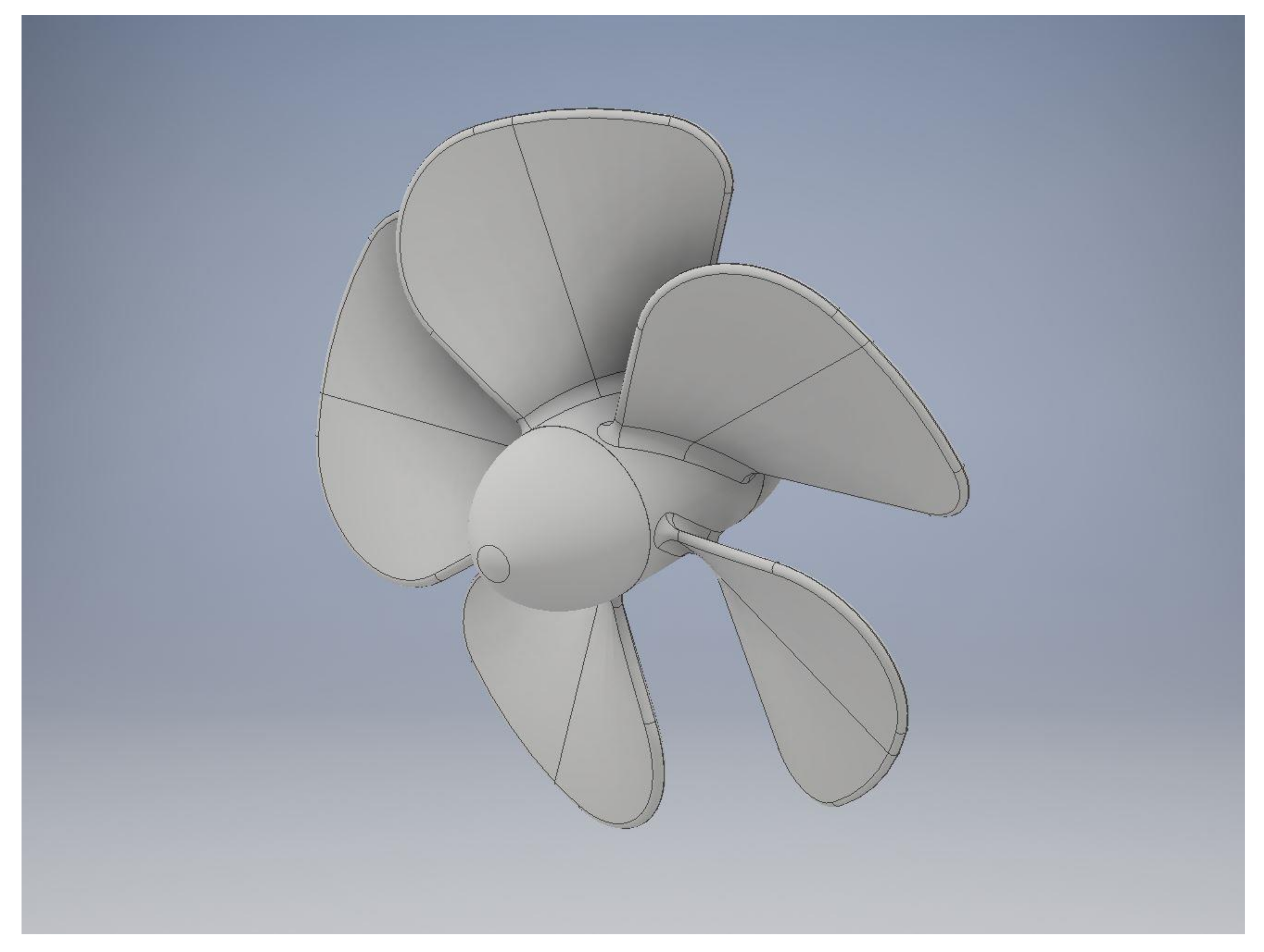
A parametric 3D model of the propeller was created in AutoCAD Inventor 2019 for CFD analyses of propeller-duct propulsion units. The main parametric dimension is the propeller diameter; the other main dimensions are related to the diameter. The geometry of the propeller is simplified so that new versions can be created seamlessly and quickly at different scales (CFD domains as needed).
Figure 1 shows the spatial model of a parametric propeller.
All propeller dimensions are parametric and depend on the diameter, including the radius of curvature and the dimensions of the propeller cones.
Table 1 lists the main propeller parameters.
The simplifications result in this parametric propeller not achieving the efficiencies guaranteed by long-term optimized commercial propellers. However, this is not a condition for performing comparative analyses, where the main criteria are the relative thrust and power of the propulsion units treated as compact functional assemblies internally composed from the propeller, duct, and throttles. The optimization of the propeller itself was not the focus of this study; identical propellers have been used within a certain series of numerical experiments. It can be foreseen that the propellers offered on the market as standard will probably not be the most optimal solution and it will be necessary to develop a new type for this special drive system.
The geometry of the duct is very interesting for the following reasons. It must provide the necessary water supply, prevent air intake, ensure high performance even in a serial group arrangement, and create robust protection for the entire propulsion unit. The maximum area that has been used for the complex geometries of the propeller and the duct tetrahedral mesh is 50 mm. The sizing was controlled by curvature and proximity; close to the walls, the minimum size of elements was 1 mm. The rest of the CFD domain was meshed by hexahedral elements varying from 50 mm to 200 mm in size depending on the distance from the propulsion unit (50 mm valid for the near zone, 200 mm valid for the far zone).
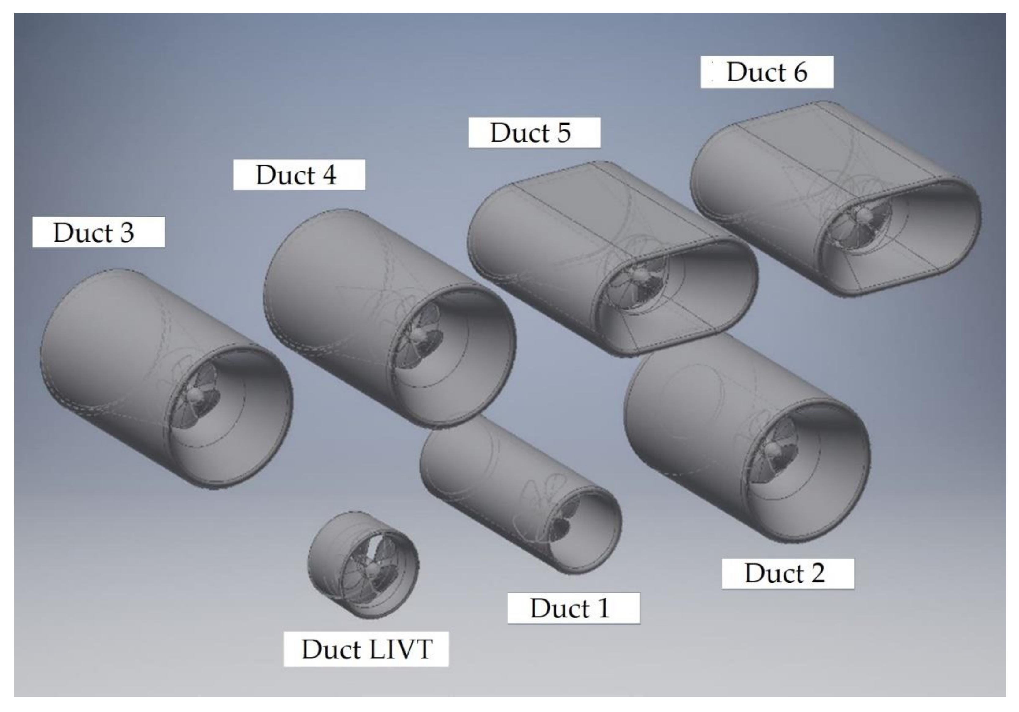
Seven parametric 3D models of different nozzles have been created:
Duct LIVT (0)—this is an existing and proven geometry developed in St. Petersburg and serves as a comparison basis for other cases;
Duct 1—extended standard duct without changing the internal cross-section. The propeller is more inserted into the duct for better protection against air intake;
Duct 2—extended duct with enlarged circular inflow cross-section and inlet tapered duct (continuously decreasing flow cross-section) and cylindrical outflow part;
Duct 3—based on the geometry of Duct 2, it also has an outlet diffuser (continuously increasing flow cross-section) in the outlet part of the duct;
Duct 4—based on the geometry of Duct 3, it also has a conical throttle body inserted into the interior of the diffuser, as a continuous continuation of the propeller hub;
Duct 5—extended duct with enlarged oval inflow and outflow cross-section, with inlet tapered duct and outlet diffuser;
Duct 6—based on the geometry of Duct 5, it also has a conical throttle body inserted into the interior of the diffuser, as a continuous continuation of the propeller hub.
All types were designed for the same propeller in one series of CFD analyses. For better comparison and evaluation of the results, the areas of the inlet and outlet cross-sections of the ducts were also unified. The first typical cross-section is actually identical to the propeller action surface, and it was used at Duct Inlets and Outlets 0 and 1, and also at Duct Outlet 2. The second typical cross-section was determined on the basis of the maximum usable outer diameter of the round duct under limited draft conditions. This cross-sectional area is the same as in the case of the inlet and outlet openings of Ducts 3 to 6 and also in the case of the inlet cross-section of Duct 2. 3D models of the examined ducts are shown in
Figure 2.
As shown in
Figure 2, some dimensions and proportions of the ducts appear to be skewed. This is deliberately exaggerated so that the different properties of the ducts are more pronounced in the results of the comparative analyses.
On the other hand, it was generally assumed that the resistance of these ducts would increase sharply with increasing speed and the propellers would have reduced combined efficiency.
2.1. Closed CFD Domain Performance Analysis
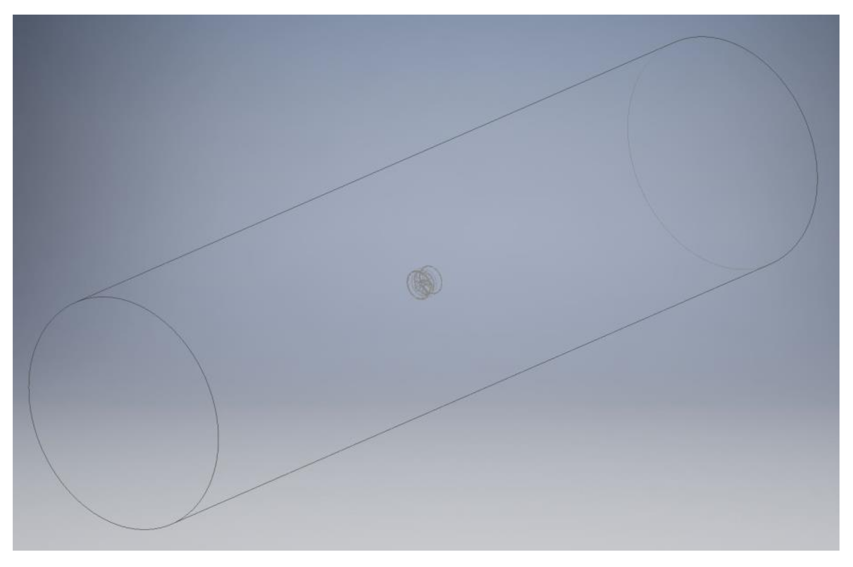
A separate propulsion unit was placed in the axis of a closed cylindrical CFD domain (
Figure 3), which was perfectly filled with only one phase, water. The analysis was performed for propulsion units equipped with the ducts LIVT (0), 1, 2, 3, 4, 5, and 6, at flow velocities v = 0, 1, 2, 3, 4, 5 and 6 m/s.
The diameter of the propellers and their speed were uniformly set to D = 500 mm and n = 1500 rpm.
The dimensions of the closed cylindrical CFD domain are shown in
Table 2.
CFD analyses were performed with the same system parameters set out in
Table 3. In each case, only the boundary conditions and initialization values differed.
The aim of these analyses was to determine the performance properties of individual propulsor designs, especially the thrust and shaft power, excluding the influence of the free surface, limited depth, or the nearby wall. The results are comparative graphs designed to support further decision-making.
2.2. Open CFD Channel Performance Analysis in Shallow Water
A separate propulsion unit was placed in an open hexahedral CFD channel (
Table 4) in the presence of two phases: air and water. Their interface formed a free surface in the channel.
The analysis was performed under conditions of limited depth (shallow water) for propulsion units equipped with the ducts LIVT (0), 3, 5, and 6, at flow velocities v = 0, 3, and 6 m/s.
The diameter of the propellers was uniformly set to D = 500 mm and their speed was gradually set to values of n = 1000, 1500, and 2000 rpm.
CFD analyses were performed with the same system parameters set as in
Table 3 in
Section 2.1, except that the model assumes an open channel and not a closed tube. In each case, only the boundary conditions and the initialization values differed.
The aim of these analyses was to determine the performance characteristics of individual propulsion designs, especially the thrust and shaft power, taking into account the influence of the free surface, limited depth, and the nearby wall representing the vertical side of the ship.
2.3. Comparison of Performances in Shallow and Deep Water
A separate propulsion unit was placed in an open hexahedral CFD channel in the presence of two phases: air and water (
Figure 4). Their interface formed a free surface in the channel.
The analysis was performed under conditions of limited and unrestricted depth (shallow and deep water) for propulsion units equipped with type 4 and 6 ducts, at flow velocities v = 0, 3, and 6 m/s.
The diameter of the propellers and their speed were uniformly set to D = 500 mm and n = 1500 rpm.
The aim of these analyses was to determine the performance properties of two selected propulsion designs, mainly thrust and shaft power and their dependence on the water depth. The results are comparative graphs designed to support further decision-making.
3. Results
In this phase of investigation, only the drag forces acting on walls of the propulsion units and the hydrodynamic torque generated by propellers have been recorded to obtain the thrust force and the absorbed power values and to construct their comparative graphs.
Analyses were performed on an initial set of potential propulsors, which were gradually limited and modified. The criteria for selecting the most suitable propulsion solutions were as follows: maximum thrust force (thrust) at minimum absorbed (shaft) power (this is an optimization of traction power and efficiency, whose validity is generally applicable); maximum inflow volume at the optimum induced axial velocity (the duct must ensure the supply of the required amount of water with minimum resistance, but the axial acceleration of the flow on the outlet side has its optimum rate). As the current acceleration increases, the efficiency increases, but the thrust force decreases. At the same time, high flow velocities on the outlet side have other undesirable effects with distributed propulsion systems; minimum height dimension of the unit with the maximum possible immersion (lower propulsion unit allows deeper immersion, which results in an increase in the critical distance of its highest point from the free surface); maximum protection against air intake and sufficient structural robustness (robust duct shape eliminates ventilation and ensures sufficient resistance to damage).
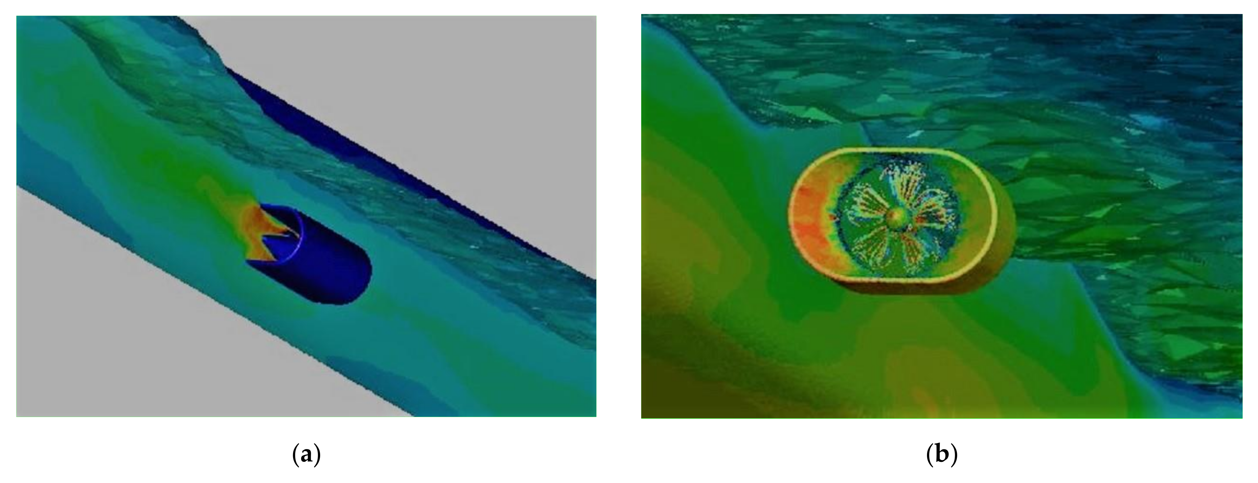
Figure 5 shows examples of 3D CFD analysis outputs under different conditions.
3.1. Results of Analyses in a Closed CFD Domain
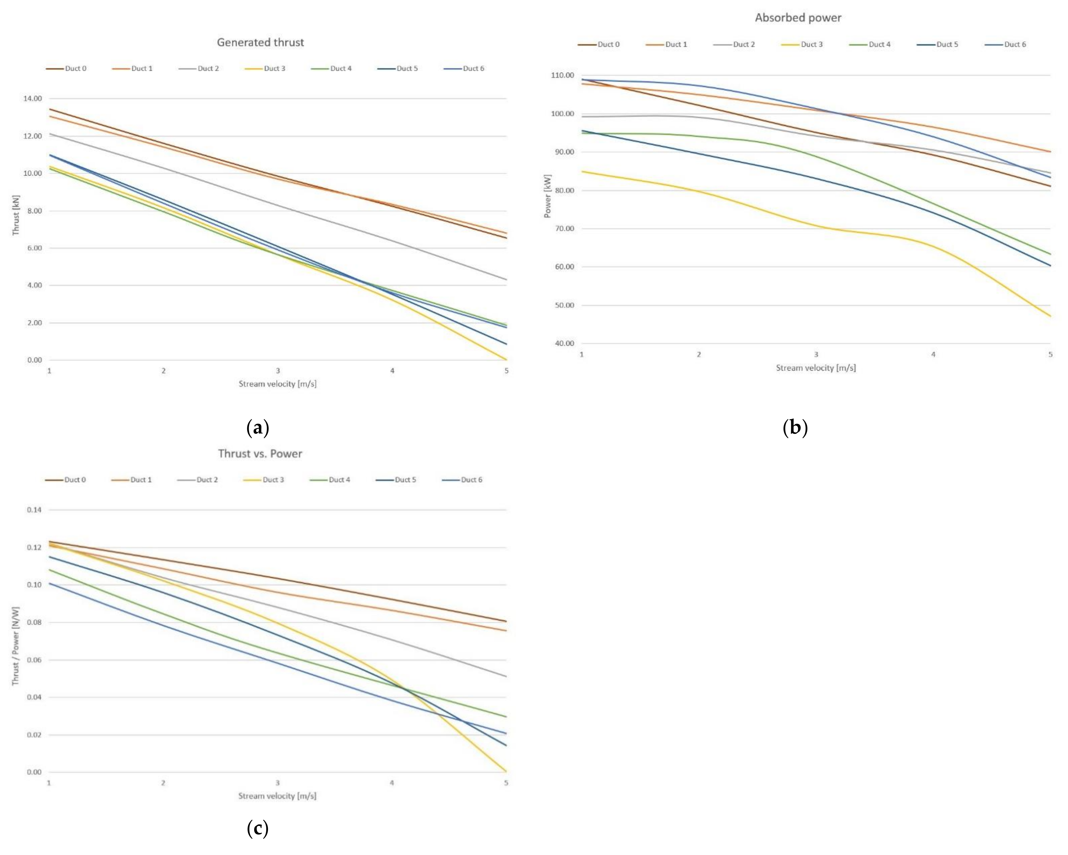
Based on the numerical flow analyses performed, the main power characteristics of the propellers were compiled in the form of the comparative graphs shown in
Figure 6. The figure shows graphs of the generated thrust/absorbed power, which was introduced instead of propulsion efficiency. Some analyses have also been performed for zero speed, for which the effective power and thus the efficiency is also zero.
Based on the comparative graphs and other output data, the individual propeller duct designs were evaluated as follows: LIVT duct—although it is not suitable for working in “open water”, it was further explored as a benchmark for other propulsors; Ducts 1 and 2—although they had a very good thrust / power ratio, they were excluded from further analyses mainly due to their excessive acceleration of the axial flow, but also for other disadvantageous properties; Ducts 3 and 4—due to the circular cross-section and the large duct height, an increased susceptibility to suction was expected. Duct 3 was launched for further examination in an open tunnel to demonstrate and confirm this; Ducts 5 and 6—do not have the best thrust / power ratios, but at low speeds they give a higher thrust force than their circular analogues, Ducts 3 and 4. In addition, they have very advantageous properties, such as low duct height, suction preferably from the sides and not from below or from above, small flow acceleration, and large increase in pressure on the outlet side. Both versions were further investigated below the free surface.
3.2. Results of Analyses in an Open CFD Channel
Four of the duct designs were analyzed in the open channel: the units equipped with the LIVT duct (0), and Ducts 3, 5, and 6. In this section, the results are presented depending on the propeller speed in the form of comparison graphs for different water flow rates (
Figure 7,
Figure 8,
Figure 9 and
Figure 10), as well as using the performance characteristics of each individual propulsor (
Figure 11,
Figure 12 and
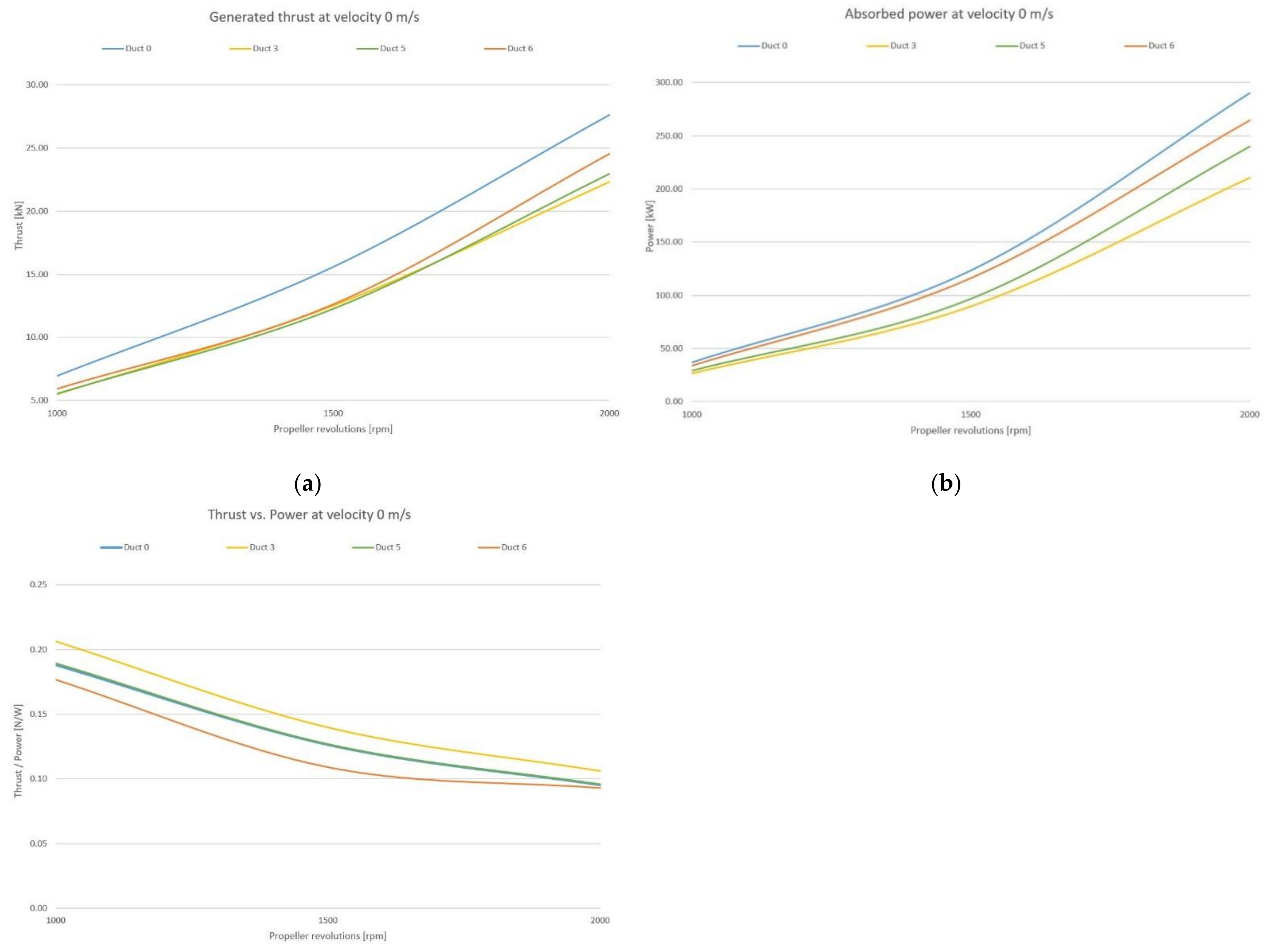
Figure 13). Comparison graphs for a flow velocity of 0 m/s are shown in
Figure 7.
The comparison of the curves in
Figure 7 shows the following properties of the different solutions (standing vessel—case of Bollard Pull Test): The LIVT duct propulsion unit generates a large thrust force and at the same time absorbs considerable power, but the thrust/power ratio is only average. At low forward speeds, ventilation is likely to occur. The propulsion unit with Duct 3 has the weakest thrust, but the best thrust/power ratio. The major disadvantage is its susceptibility to ventilation at low speeds. Units with Ducts 5 and 6 reach average values, with Duct 6 having the worst thrust/power ratio. Both units are safe to suck.
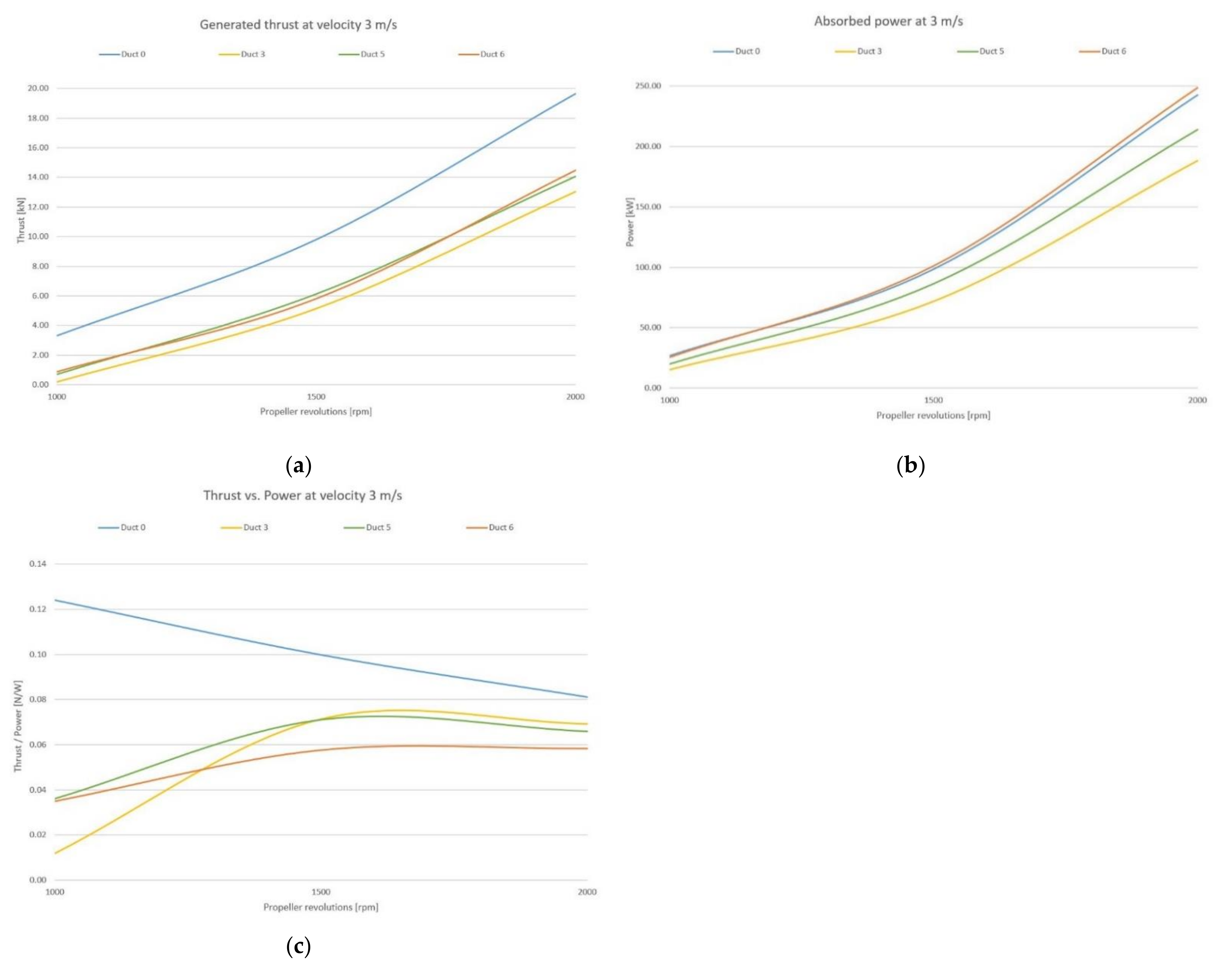
Propulsion ventilation at low speeds is a very unfavorable phenomenon. It can lead to a significant decrease in the thrust of the propeller. This will make the vessel unable to start and reach the range of operating speeds. Comparison graphs for a flow velocity of 3 m/s are shown in
Figure 8.
The comparison of the curves in
Figure 8 shows the following properties of the individual designs. The LIVT duct propulsion unit generates a large thrust force even at low propeller speeds, thanks to the considerable additional thrust of the duct itself. Duct 3 has the weakest thrust and at low speeds, the additional thrust passes to the negative part; i.e., it increases the resistance; Units with Ducts 5 and 6 achieve values comparable to duct 3. Duct 6 has the worst thrust/power ratio. However, at lower speeds it has a higher additional thrust than Duct 3.
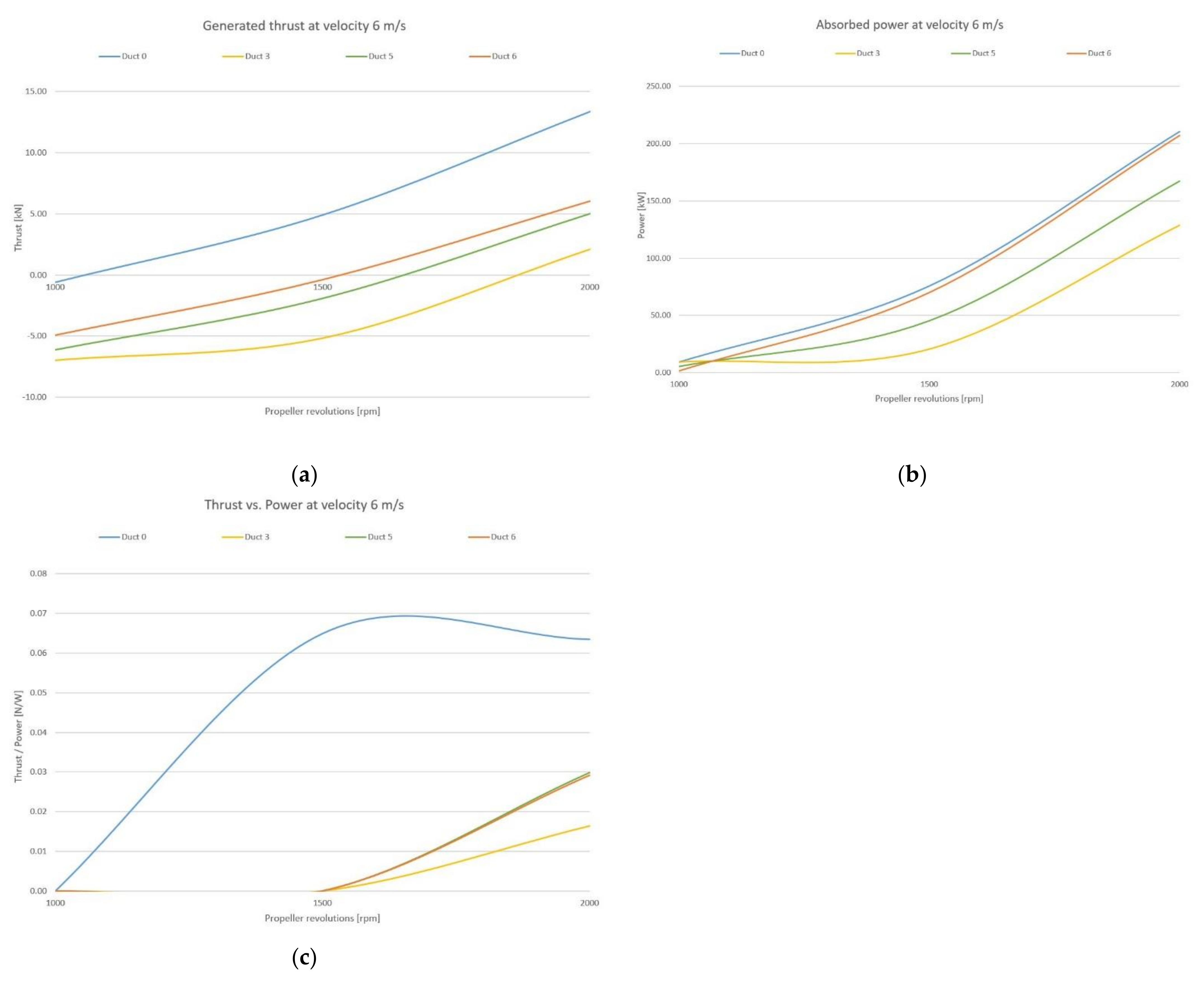
As the water flow velocity increases, the hydrodynamic properties of the ducts become more and more pronounced; after reaching a certain characteristic speed, each duct begins to resist movement instead of generating additional thrust. Comparison graphs for a flow velocity of 6 m/s are shown in
Figure 9.
The curves in the graphs shown in
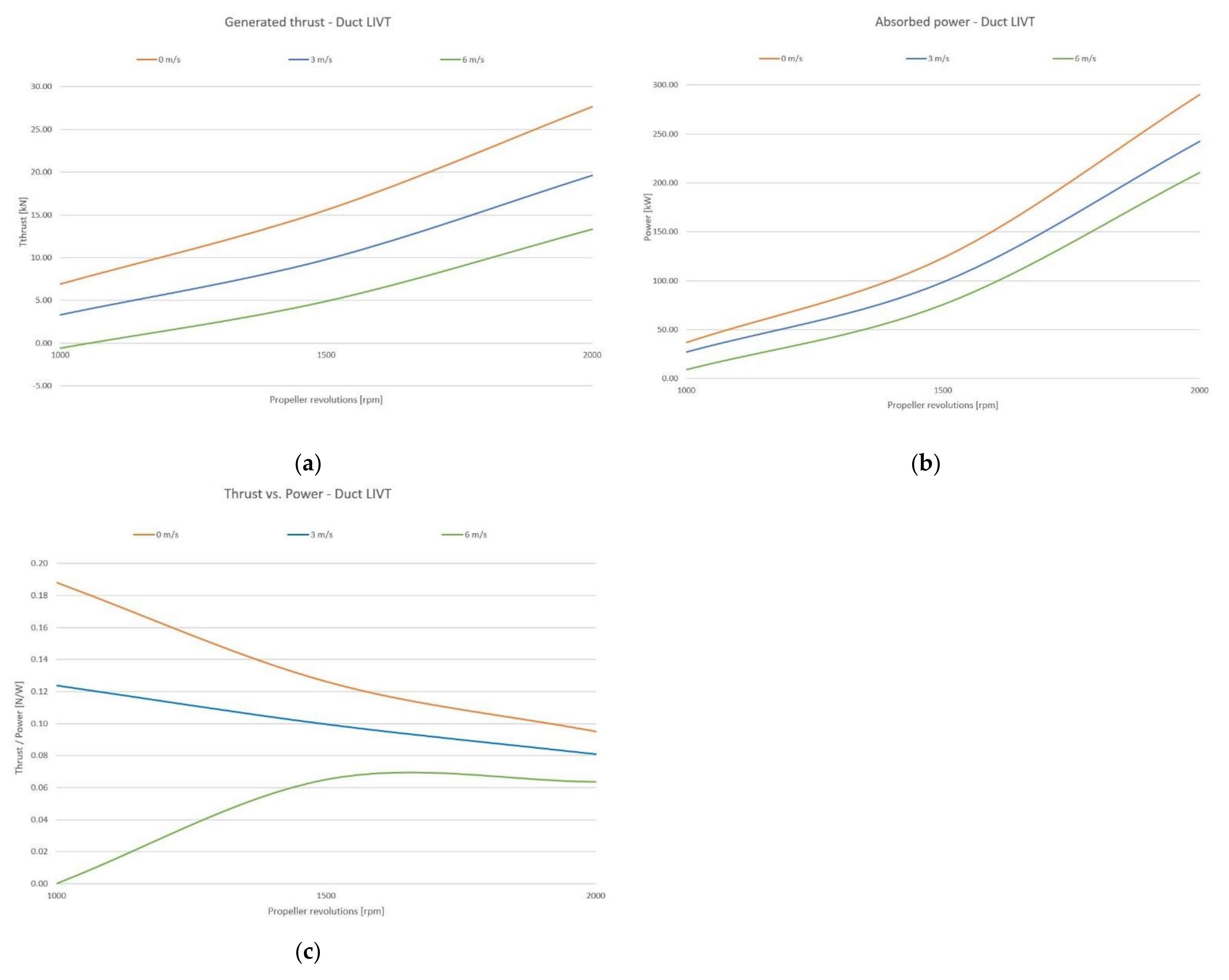
Figure 9 show that, for all the proposed units except the LIVT duct, speed is limiting. Units with Ducts 5 and 6 start to generate thrust in the working area of the propeller, at 1500 rpm. The propulsion with Duct 3 is worse, as it needs a relatively high speed to create a thrust. The duct formed in this way generates more resistance at this speed. The performance characteristics of the LIVT duct propulsion unit are shown in
Figure 10.
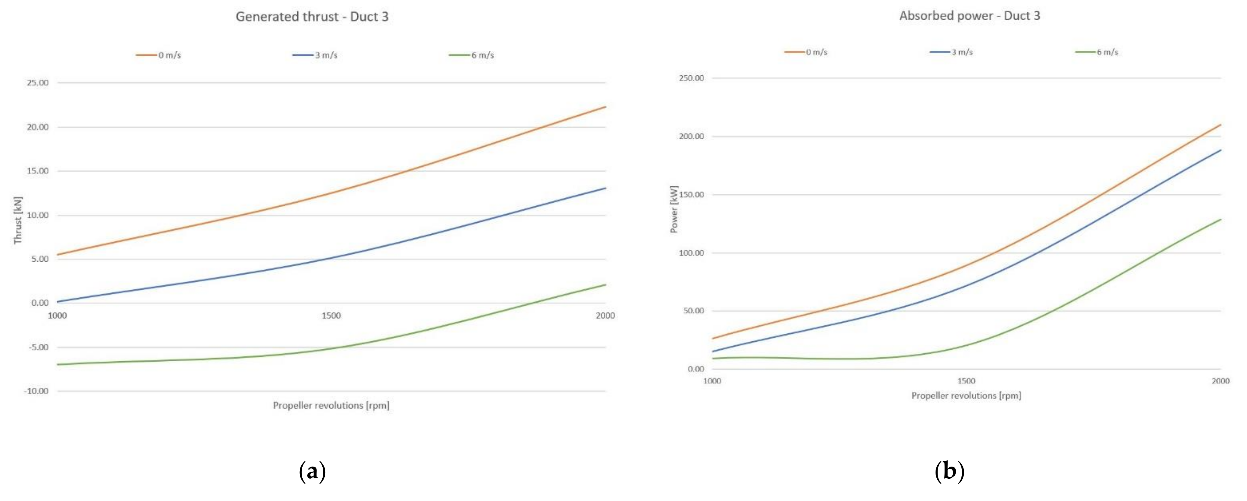
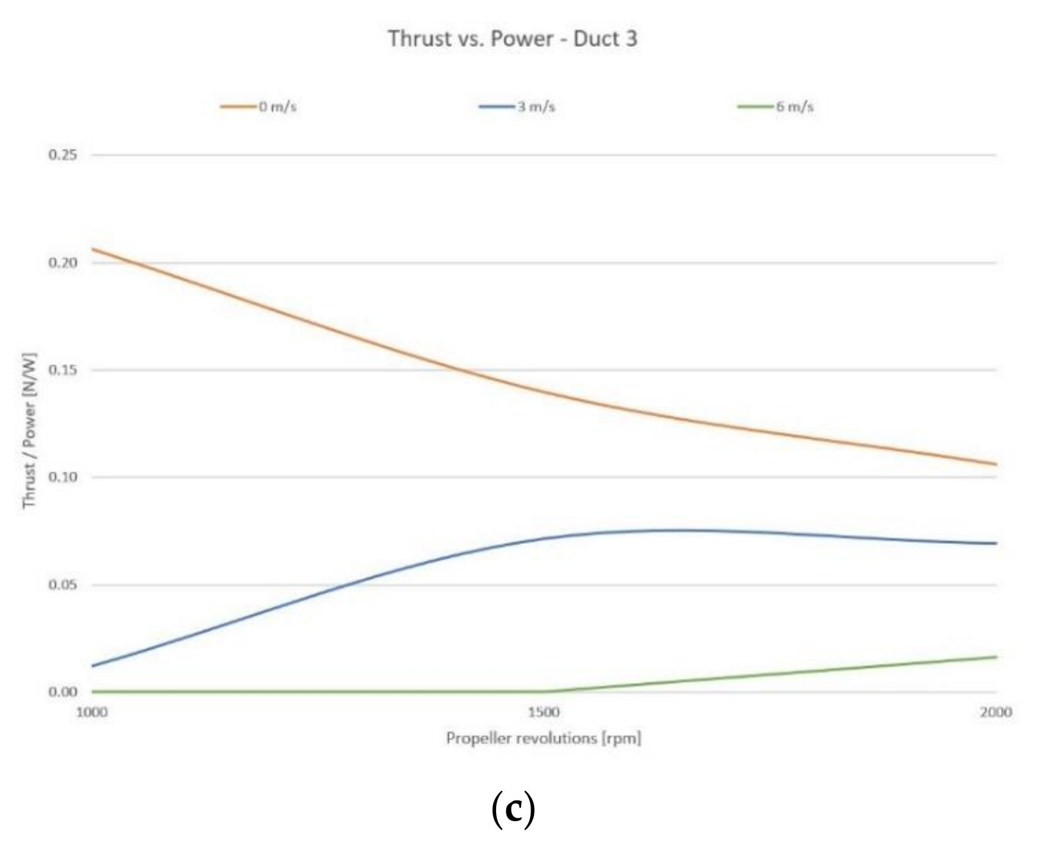
The performance characteristics of the Duct 3 propulsion unit are shown in
Figure 11.
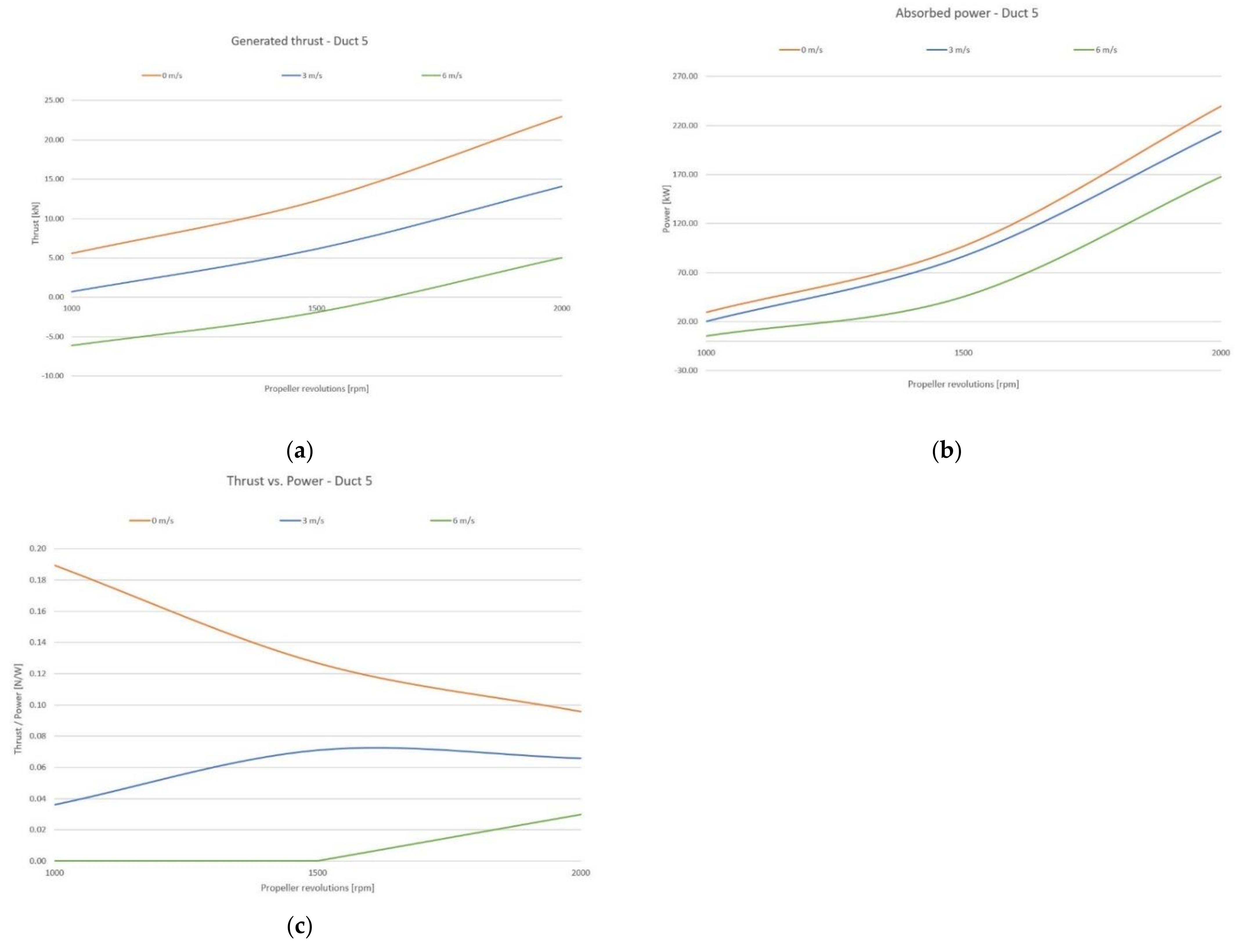
The performance characteristics of the Duct 5 propulsion unit are shown in
Figure 12.
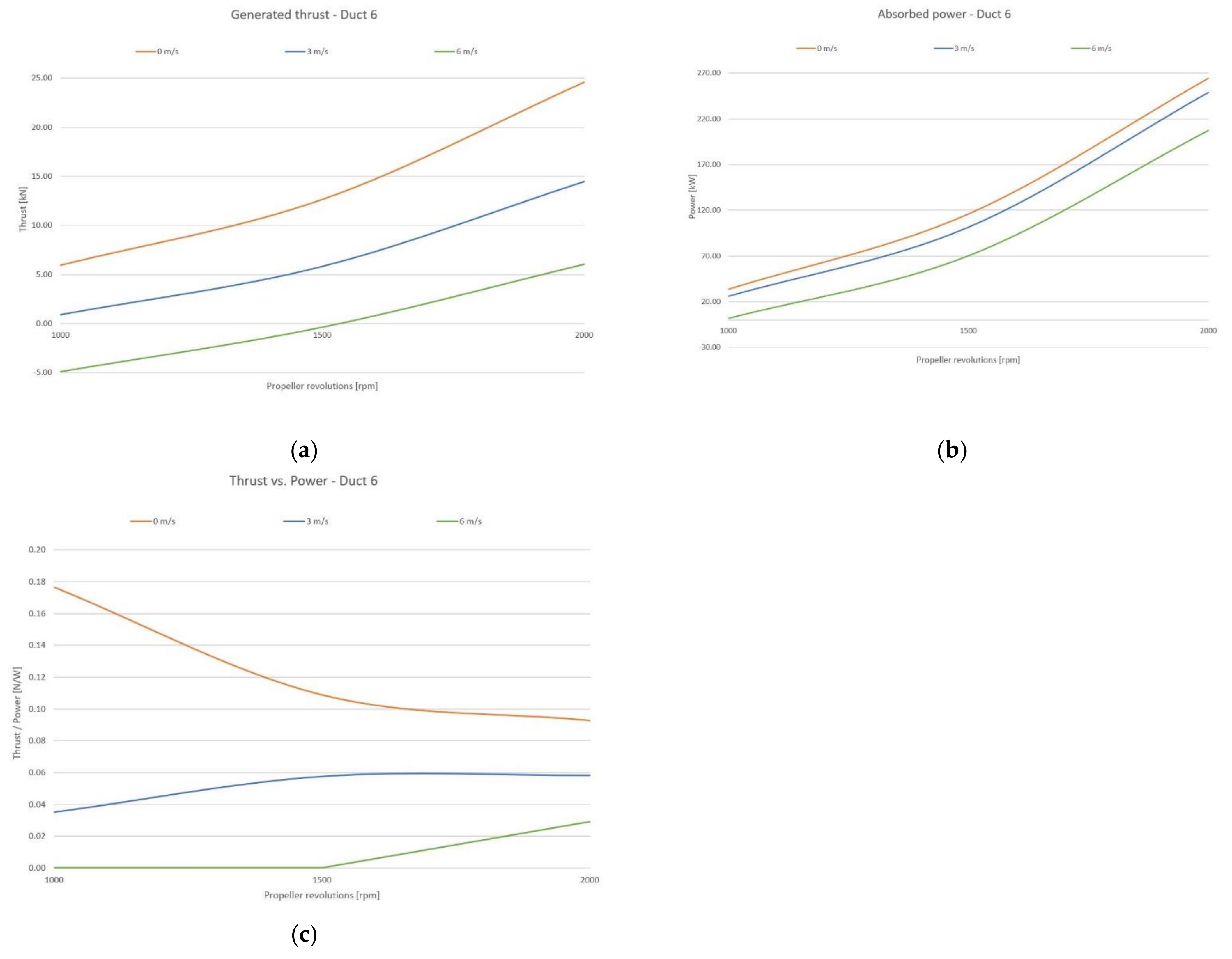
The performance characteristics of the Duct 6 propulsion unit are shown in
Figure 13.
In these comparative graphs, but also in the performance characteristics, there are easily identifiable turning points or equilibrium, where the thrust force of the propulsor transitions to the resistance force and vice versa. In general, this is the point where the curve passes through the x-axis of the graph.
In most cases, this resistive force arises on the duct body and other passive parts of the propulsor. Its size and the position of the turning point depend on their hydrodynamic resistance coefficient.
At higher forward speeds and at low propeller revolutions, a situation may arise where the propeller can no longer accelerate the axial flow and thus generates a resistive force instead of a thrust force.
3.3. Influence of Water Depth on Propulsion Performance
In this study, a special analysis was performed to investigate the water depth effect on the performance of separated propulsion units. The thrust curves of the propulsion units equipped with Ducts 4 and 6 are shown in
Figure 14.
Both graphs show the minimum dependence of the thrust/performance on the water depth in the range of real navigation depths. The difference in the force in the middle part of the graph, in the area of probable operating speeds, is at the level of the numerical error of the calculation method.
This is a very important finding that the investigated propulsion units, located on the side of the hull, practically do not lose performance in limited conditions (shallow water), in contrast to the traditional stern arrangement of the propulsion units.
This is also confirmed by the interpretation of the results of the analyses carried out in the first stage of the research [
21] and is another argument for the choice of serially-arranged distributed propulsion systems placed symmetrically on both sides of the ship.
4. Discussion
The issue of propeller-type drives has been very well researched and elaborated in detail. New results and knowledge are gradually being incorporated into the basic theory of propulsion, but propeller theory is also being solved in parallel by other alternative ways and methods. Several such theories and methods have been developed and published, and have recently received considerable support due to the accessibility and widespread use of high-performance hardware and software capable of solving hydrodynamic flow problems in a numerical manner (especially the CFD method).
This study does not go into detail about propeller theory. As part of the study of propulsion systems, the propeller itself was not optimized further, nor were extensive theoretical calculations performed. This could be the subject of further research, as well as the interaction of distributed propulsion systems with the hull.
However, the current situation is completely different in terms of theory and reference work on distributed propulsion systems. Due to the lack of publications related to restricted draft, it was not possible to build on previous research, build on its results, or rely on its conclusions.
In some countries (e.g., the Netherlands, China) there is evidence of research related to new types of propulsion systems for vessels sailing in restricted waters, but the results have not yet been published.
Similar research, development, and related multi-propeller experiments have been performed in the past for a different reason: as a matter of achieving a better longitudinal distribution of the impact thrust force in terms of propeller loading and harmful cavitation phenomena. The best-known cases are overlapping propellers and tandem propellers, which have also been implemented on experimental ships. Each overlapping propeller has its own shaft line, while the tandem system is mounted on one common shaft. However, all these propellers are located in the traditional position below the ship stern (stern arrangement), which is a significant difference from the arrangement of propellers along the side of the ship. These historical systems also tend to appear as integrated propulsion units due to their small distance from each other.
Due to their significant differences from the distributed arrangements and insufficient documentation of these systems, these systems were not used in the study as reference cases/studies, or as a comparison basis for evaluating the results.
Due to the above reasons for the final verification of the working method and validation, it was not possible to compare our results based on CFD analyses with other published results from previous research, which were based on either computer simulations or model tests performed in basin. Similar research examining the longitudinal distribution of propulsion units along the side of the ship, which would make it possible to verify and compare the results, is not currently available.
5. Conclusions
The aim of the research was to eliminate the disadvantages of traditional stern propulsion systems and to design a new type of propulsor that can work efficiently in other configurations. Positions outside the hull of the ship were assessed when operating in open water conditions and at limited navigable depths.
Such distributed propulsion systems must have low sensitivity to limited water depth and at the same time must handle well the supply of sufficient water. Based on the results achieved, the preliminary assumptions were confirmed at least at the level of the CFD simulation. As a matter of priority, tests should also be carried out in a test basin or tunnel to examine the actual characteristics of the individual distributed propulsion systems.
Analyses have shown that Ducts 5 and 6 have sufficient resistance to ventilation at limited depths and deliver acceptable performance at low inflow and outflow rates (this feature is important in serial arrangements). Their performance can be further increased by reducing the resistance of the duct at higher speeds, which could be the task of another research and development project focused on the geometry of components.
However, these results do not preclude the use of other types of propellers for future ships designed to navigate at limited navigable depths. In the preparatory phase of the research, test analyses were also performed for special side paddle wheels and water jet propulsors, but the preliminary results in limited conditions were not convincing.
This study shows a possible way in which the propulsion units of future ships operating at limited navigable depths could be developed with different arrangements of distributed propulsion systems. These vessels could navigate on inland waterways where ships with a traditional hull and propulsion no longer can, whether for technical or economic reasons, and their deployment is suitable for both freight and passenger transport.
Further research and development should focus on the development of special propellers and ducts for compact propulsor modules of hulls optimized for optimal interaction in conditions of both limited and unrestricted navigation.
Author Contributions
Conceptualization, L.I., M.J., O.S. and T.K. (Tomas Kalina); methodology, L.I., M.J. and J.S.; software, L.I., M.J. and O.S.; validation, L.I., M.J. and P.G.; formal analysis, M.J., J.S. and T.K. (Tibor Kubjatko); investigation, L.I., M.J. and T.K. (Tomas Kalina); resources, M.J. and J.S.; data curation, L.I. and M.J.; writing—original draft preparation, L.I. and M.J.; writing—review and editing, M.J. and O.S.; visualization, L.I., P.G. and T.K. (Tibor Kubjatko); supervision, M.J. and T.K. (Tomas Kalina); project administration, M.J.; funding acquisition, M.J. All authors have read and agreed to the published version of the manuscript.
Funding
This research received no external funding.
Institutional Review Board Statement
Not applicable.
Informed Consent Statement
Not applicable.
Data Availability Statement
Not applicable.
Acknowledgments
This research is the result of the Project VEGA No. 1/0128/20: Research on the Economic Efficiency of Variant Transport Modes in Car Transport in the Slovak Republic with Emphasis on Sustainability and Environmental Impact, Faculty of Operation and Economics of Transport and Communications, University of Zilina, 2020–2022. This publication was also created thanks to support under the Operational Program Integrated Infrastructure for the project: Identification and possibilities of implementation of new technological measures in transport to achieve safe mobility during a pandemic caused by COVID-19 (ITMS code: 313011AUX5), co-financed by the European Regional Development Fund.
Conflicts of Interest
The authors declare no conflict of interest.
References
- Buchler, D.; Luck, R.; Markert, M. Propulsion and control system for shallow water ships based on surface cutting double Propellers. In Proceedings of the 8th IFAC Conference on Control Applications in Marine Systems, Rostock-Warnemunde, Germany, 15–17 September 2010. [Google Scholar]
- Rotteveel, E.; Hekkenberg, R.; van der Ploeg, A. Inland ship stern optimization in shallow water. Ocean Eng. 2017, 141, 555–569. [Google Scholar] [CrossRef]
- Raven, H. A new correction procedure for shallow-water effects in ship speed trials. In Proceedings of the 13th International Symposium on PRActical Design of Ships and Other Floating Structures PRADS’ 2016, Copenhagen, Denmark, 4–8 September 2016. [Google Scholar]
- Lackenby, H. The effect of shallow water on ship speed. Shipbuild. Mar. Eng. 1963, 70, 446–450. [Google Scholar]
- Tuck, E. Hydrodynamic problems of ships in restricted waters. Annu. Rev. Fluid Mech. 1978, 10, 33–46. [Google Scholar] [CrossRef]
- Ferreiro, L.D. The effects of confined water operations on ship performance: A guide for the perplexed. Nav. Eng. J. 1992, 104, 69–83. [Google Scholar] [CrossRef]
- Rotteveel, E.; Hekkenberg, R. The influence of shallow water and hull form variations on inland ship resistance. In Proceedings of the 12th International Marine Design Conference (IMDC), Tokyo, Japan, 11–14 May 2015. [Google Scholar]
- Raven, H. A computational study of shallow-water effects on ship viscous resistance. In Proceedings of the 29th Symposium on Naval Hydrodynamics, Gothenburg, Sweden, 26–31 August 2012. [Google Scholar]
- Graff, W.; Kracht, A.; Weinblum, G. Some extensions of D.W. Taylor’s standard series. Trans. SNAME 1964, 72, 375–401. [Google Scholar]
- Terziev, M.; Tezdogan, T.; Oguz, E.; Gourlay, T.; Demirel, Y.K.; Incecik, A. Numerical investigation of the behaviour and performance of ships advancing through restricted shallow waters. J. Fluid Struct. 2018, 76, 185–215. [Google Scholar] [CrossRef] [Green Version]
- Lataire, E.; Vantorre, M. Ship-bank interaction induced by irregular bank geometries. In Proceedings of the 27th Symposium in Naval Hydrodynamics, Seoul, Korea, 5–10 October 2008. [Google Scholar]
- Eloot, K.; Delefortrie, G.; Vantorre, M. Inland navigation: Assessing the manoeuvring behaviour for real-time simulation purposes. In Proceedings of the MARSIM Conference, Singapore, 23–27 April 2012. [Google Scholar]
- Zhou, X.Q.; Sutulo, S.; Guedes Soares, C. A paving algorithm for dynamic generation of quadrilateral meshes for online numerical simulations of ship manoeuvring in shallow water. Ocean Eng. 2016, 122, 10–21. [Google Scholar] [CrossRef]
- Xu, H.T.; Hinostroza, M.A.; Wang, Z.; Guedes Soares, C. Experimental investigation of shallow water effect on vessel steering model using system identification method. Ocean Eng. 2020, 199, 106940. [Google Scholar] [CrossRef]
- Zhou, X.Q.; Sutulo, S.; Guedes Soares, C. Ship-Ship hydrodynamic interaction in confined waters with complex boundaries by a Panelled Moving Patch Method. RINA Int. J. Marit. Eng. 2016, 158, 21–30. [Google Scholar] [CrossRef]
- Themelis, N.; Spandonidis, C.C.; Giordamlis, C. Data acquisition and processing techniques for a novel performance monitoring system based on KPIs. In Sustainable Development and Innovations in Marine Technologies, 1st ed.; CRC Press: Boca Raton, FL, USA, 2019; pp. 306–315. [Google Scholar]
- Ferziger, J.H.; Peric, M. Computational Methods for Fluid Dynamics; Springer: Berlin/Heidelberg, Germany, 2002. [Google Scholar] [CrossRef]
- Illes, L.; Jurkovic, M.; Kalina, T.; Gorzelanczyk, P.; Luptak, V. Methodology for Optimising the Hull Shape of a Vessel with Restricted Draft. Sci. J. Sil. Univ. Technol. Ser. Transp. 2021, 110, 57–71. [Google Scholar] [CrossRef]
- David, A.; Madudova, E. The Danube river and its importance on the Danube countries in cargo transport. In Proceedings of the 13th International Scientific Conference on Sustainable, Modern and Safe Transport, TRANSCOM 2019, High Tatras, Slovakia, 29–31 May 2019. [Google Scholar]
- Mako, P.; Galierikova, A. Inland navigation on the Danube and the Rhine waterways. In Proceedings of the 14th International Scientific Conference on Sustainable, Modern and Safe Transport, TRANSCOM 2021, Horny Smokovec, Slovakia, 26–28 May 2021. [Google Scholar]
- Illes, L.; Kalina, T.; Jurkovic, M.; Luptak, V. Distributed Propulsion Systems for Shallow Draft Vessels. J. Mar. Sci. Eng. 2020, 8, 667. [Google Scholar] [CrossRef]
Figure 1.
Parametric 3D model of the propeller.
Figure 1.
Parametric 3D model of the propeller.
Figure 2.
3D duct geometry.
Figure 2.
3D duct geometry.
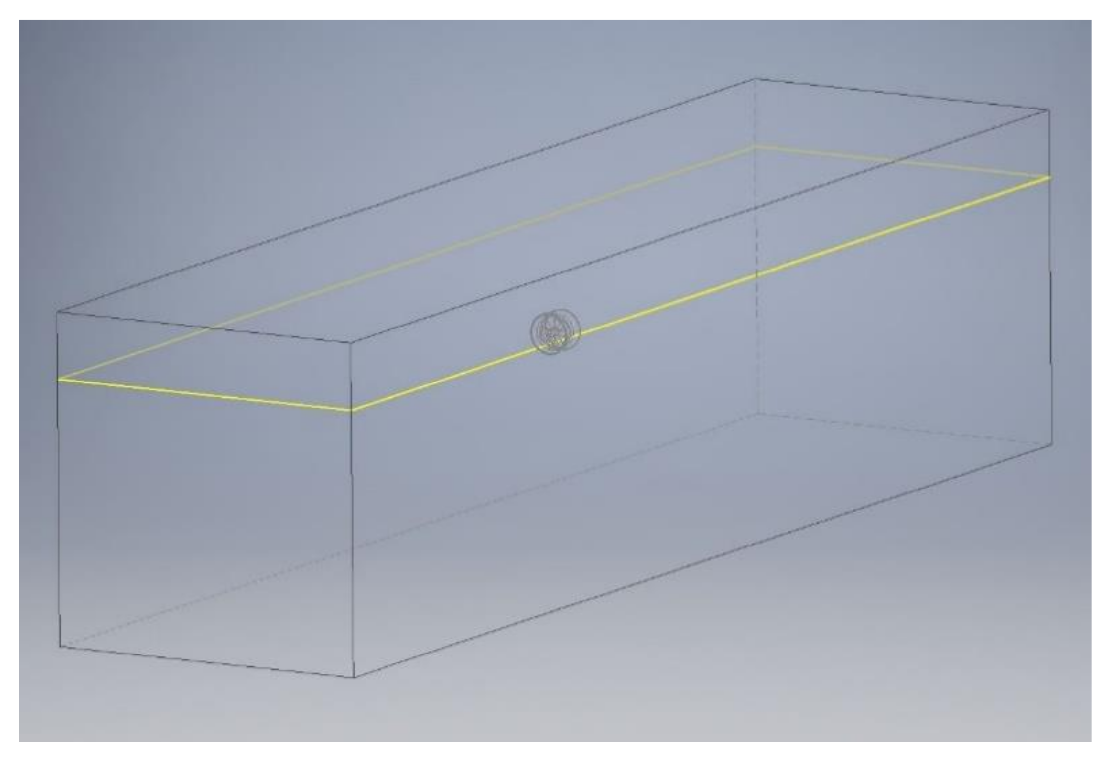
Figure 3.
3D geometry of a closed cylindrical CFD domain (LIVT duct).
Figure 3.
3D geometry of a closed cylindrical CFD domain (LIVT duct).
Figure 4.
3D geometry of open hexahedral CFD channel (LIVT duct).
Figure 4.
3D geometry of open hexahedral CFD channel (LIVT duct).
Figure 5.
Example of the 3D CFD outputs. (a) Flow velocities on free surface and in vertical middle plane; (b) dynamic pressures on propulsor and on walls of the domain.
Figure 5.
Example of the 3D CFD outputs. (a) Flow velocities on free surface and in vertical middle plane; (b) dynamic pressures on propulsor and on walls of the domain.
Figure 6.
Comparison of the main performance characteristics of propulsors. (a) Generated thrust depending on flow rate; (b) power absorbed depending on flow rate; (c) generated thrust per unit of absorbed power.
Figure 6.
Comparison of the main performance characteristics of propulsors. (a) Generated thrust depending on flow rate; (b) power absorbed depending on flow rate; (c) generated thrust per unit of absorbed power.
Figure 7.
Comparison of parameters for flow velocity 0 m/s. (a) Generated thrust at velocity 0 m/s; (b) absorbed power at velocity 0 m/s; (c) generated thrust per unit of absorbed power at the speed of 0 m/s.
Figure 7.
Comparison of parameters for flow velocity 0 m/s. (a) Generated thrust at velocity 0 m/s; (b) absorbed power at velocity 0 m/s; (c) generated thrust per unit of absorbed power at the speed of 0 m/s.
Figure 8.
Comparison of parameters for flow velocity of 3 m/s. (a) Generated thrust at velocity 3 m/s; (b) absorbed power at velocity 3 m/s; (c) generated thrust per unit of absorbed power at the speed of 3 m/s.
Figure 8.
Comparison of parameters for flow velocity of 3 m/s. (a) Generated thrust at velocity 3 m/s; (b) absorbed power at velocity 3 m/s; (c) generated thrust per unit of absorbed power at the speed of 3 m/s.
Figure 9.
Comparison of parameters for flow velocity 6 m/s. (a) Generated thrust at velocity 6 m/s; (b) absorbed power at velocity 6 m/s; (c) generated thrust per unit of absorbed power at the speed 6 m/s.
Figure 9.
Comparison of parameters for flow velocity 6 m/s. (a) Generated thrust at velocity 6 m/s; (b) absorbed power at velocity 6 m/s; (c) generated thrust per unit of absorbed power at the speed 6 m/s.
Figure 10.
Performance characteristics of propeller with LIVT duct. (a) Generated thrust for different speeds depending on the propeller speed; (b) absorbed power for different speeds depending on propeller speed; (c) generated thrust per unit of power absorbed.
Figure 10.
Performance characteristics of propeller with LIVT duct. (a) Generated thrust for different speeds depending on the propeller speed; (b) absorbed power for different speeds depending on propeller speed; (c) generated thrust per unit of power absorbed.
Figure 11.
Performance characteristics of propeller with Duct 3. (a) Generated thrust for different speeds depending on the propeller speed; (b) absorbed power for different speeds depending on propeller speed; (c) generated thrust per unit of power absorbed.
Figure 11.
Performance characteristics of propeller with Duct 3. (a) Generated thrust for different speeds depending on the propeller speed; (b) absorbed power for different speeds depending on propeller speed; (c) generated thrust per unit of power absorbed.
Figure 12.
Performance characteristics of propeller with Duct 5. (a) Generated thrust for different speeds depending on the propeller speed; (b) absorbed power for different speeds depending on propeller speed; (c) generated thrust per unit of power absorbed.
Figure 12.
Performance characteristics of propeller with Duct 5. (a) Generated thrust for different speeds depending on the propeller speed; (b) absorbed power for different speeds depending on propeller speed; (c) generated thrust per unit of power absorbed.
Figure 13.
Performance characteristics of propeller with Duct 6. (a) Generated thrust for different speeds depending on the propeller speed; (b) absorbed power for different speeds depending on propeller speed; (c) generated thrust per unit of power absorbed.
Figure 13.
Performance characteristics of propeller with Duct 6. (a) Generated thrust for different speeds depending on the propeller speed; (b) absorbed power for different speeds depending on propeller speed; (c) generated thrust per unit of power absorbed.
Figure 14.
Impact curves of propulsion units. (a) Generated thrust of the propeller with Duct 4 depending on the water depth; (b) generated thrust of propeller with Duct 6 depending on the water depth.
Figure 14.
Impact curves of propulsion units. (a) Generated thrust of the propeller with Duct 4 depending on the water depth; (b) generated thrust of propeller with Duct 6 depending on the water depth.
Table 1.
The main parameters of the propeller.
Table 1.
The main parameters of the propeller.
Diameter
[m] | Hub Diameter
[m] | Hub Length
[m] | Pitch
[m] | Blade Thickness
[m] | Number of Blades
[pcs] | Area Ratio
[-] |
|---|
| D | D × 0.24 | D × 0.24 | D | D × 0.02 | 5 | 0.805 |
Table 2.
Cylindrical computational domain dimensions.
Table 2.
Cylindrical computational domain dimensions.
Length
[m] | Diameter
[m] | Number of Phases |
|---|
| 20.0 | 5.0 | 1 |
Table 3.
Set CFD system and calculation domain parameters.
Table 3.
Set CFD system and calculation domain parameters.
| Software | ANSYS Fluent v. 17.2.0 |
|---|
Solver
Model
Euler’s phases
Viscous model
Mesh type 1
Size of mesh elements 1
Mesh type 2
Size of mesh elements 2
Record | Pressure, transient
Liquid volume, without multiphase, closed tube
Fresh water
K-omega, Menter Shear Stress Transport Turbulence Model
Tetrahedral elements, propeller and duct area
Min. 1 mm, max. 50 mm, controlled by curvature and proximity
Hexahedral elements, filling the rest of the outer part of the CFD domain
Min. 50 mm valid for the near zones, max. 200 mm valid for the far zones
Drag force acting on the propulsor, propeller torque, mass flow through monitoring sections, total pressure in the monitoring areas |
Table 4.
Dimensions of the hexahedral computational domain.
Table 4.
Dimensions of the hexahedral computational domain.
Length
[m] | Width
[m] | Height (Limited)
[m] | Height (Unlimited) [m] | Water Depth (Limited) [m] | Water Depth (Unlimited) [m] |
|---|
| 20.0 | 5.0 | 2.8 | 5.0 | 1.8 | 4.0 |
| Publisher’s Note: MDPI stays neutral with regard to jurisdictional claims in published maps and institutional affiliations. |
© 2022 by the authors. Licensee MDPI, Basel, Switzerland. This article is an open access article distributed under the terms and conditions of the Creative Commons Attribution (CC BY) license (https://creativecommons.org/licenses/by/4.0/).


 ,
, 


