Review

A Review of Computational Simulation Methods for a Ship Advancing in Broken Ice

1
Department of Mechanical Engineering, Aalto University, 02150 Espoo, Finland
2
Department of Mechanical Engineering, University College London, London WC1E 6DH, UK
*
Author to whom correspondence should be addressed.
J. Mar. Sci. Eng. 2022, 10(2), 165; https://doi.org/10.3390/jmse10020165
Submission received: 26 November 2021 / Revised: 17 December 2021 / Accepted: 25 January 2022 / Published: 27 January 2022

Abstract

:
Apart from breaking level ice, polar ships can interact with broken ice in various scenarios. In recent years, computational simulation models have increasingly been used for the evaluation of ship operability under broken ice conditions, presenting some challenging issues. This paper reviews existing simulation methods used to estimate ship performance and ice loads for ships advancing continuously in broken ice fields. Models for different types of broken ice, including ice floes, ice ridges, brash ice, and sliding ice pieces, are reviewed separately. A ship’s response in broken ice is divided into two categories: resistance, which relates to the overall ship performance, and local loads, which relates to structural safety. This review shows that most existing models are proposed for unbreakable ice particles, which are only applicable to broken ice of small size; most models treat fluid flow with extensive simplification, which does not reflect the influence of a ship’s wake or bow waves, and most models are aimed at resistance estimation, adopting elastic or viscoelastic contact models which do not include ice crushing. As for future work, it is suggested that more effort should be assigned to simulating a ship’s interaction with ice ridges and sliding ice pieces, the modelling of breakable ice floes, and the coupling of the Discrete Element Method (DEM) and Computational Fluid Dynamics (CFD). More attention to the local ice load estimation is also encouraged.

1. Introduction

1.1. Forms of Broken Ice

The majority of sea ice in polar regions can be generalized into two types, (a) level ice that exists as a continuous form, and (b) broken ice that consists of discontinuous ice blocks. Broken ice includes brash ice that normally accumulates in ice channels, sliding ice pieces that form from breaking continuous ice, unconsolidated ice ridges generated by compression between ice floes, and ice floe fields (the most common broken ice condition in the polar region) that appear and evolve with natural processes.
Broken ice is discontinuous, consisting of myriad ice pieces. The ice size, shape, and distribution vary between different types of broken ice, and examples are shown in Figure 1. Brash ice rubbles, Figure 1a, are small compared to other types of broken ice and usually cover ice channels as floating layers with full concentration. The ice rubbles are relatively spherical due to repeating contact with ships and other ice rubbles. Unconsolidated ice ridge rubbles, Figure 1b, share a similar piling feature to brash ice, but the size is larger and the shape is normally not spherical. The ridge keel cross-section can be approximated as a triangle or trapezoid. Sliding ice pieces, Figure 1c, form when ice sheets are broken up by a ship; these have a similar dimension magnitude to ice ridge rubbles. The movement of these ice pieces is restricted by the existence of the intact ice sheets, forming a layer of ice pieces that covers the underwater ship body. Ice floe fields, Figure 1d, are discrete and float on the sea surface. This ice condition is described by its ice concentration, ice diameter, ice thickness, and floe shape. Ice floes with a size greater than the magnitude of ships (>500 m) are considered as level ice sheet from the perspective of ship-ice interaction, which is not within the scope of this paper.

1.2. Interaction between a Ship and Broken Ice

During the interaction between a ship and broken ice, kinetic energy is dissipated to push aside, accelerate, submerge, crush, or further break the ice pieces, as well as to compensate for friction. The differences in size and distribution among various types of broken ice result in differences in the energy dissipation process. Given the same thickness and floe shape, the failure of ice by bending and splitting is less dominant when the size of the broken ice is small, but becomes increasingly important for larger ice floes. This affects the dissipation of the ship’s kinetic energy and ultimately determines the interaction force [2]. In addition to ice failure, hydrodynamics also plays an important role in the interaction process, e.g., through added mass, drag force, and wake [3]. The fluid flow affects the motion of the ship and the ice before and after the contact and influences the force needed to break the ice [4].
The main desired outcomes of modelling a ship advancing in broken ice include an increased understanding of ice resistance and ice loads on local structures. Ice resistance is the average summation time of the force of the ice along the hull, which, in surge direction, is equivalent to the ice resistance, and in yaw direction, is the resisting turning moment of the ship. These factors relate to ship performance in areas such as attainable speed, fuel consumption, and maneuvrability in ice. Local ice load refers to the maximum force exerted on a certain part of the ship’s structure, usually impacting one or several frames. This relates to the structural safety of ships, especially for low ice-strengthened merchant ships sailing in floe fields. In this paper, the capabilities of existing simulation methods to estimate resistance and the local ice load are discussed, respectively.

1.3. Simulation of a Ship Advancing in Broken Ice

Unlike formulae used for estimating ship resistance in level ice, analytical formulae proposed for the estimation of broken ice resistance are rare, except those used for sliding ice pieces originating from a breaking ice sheet which have been integrated into the level ice resistance formulae (e.g., submersion resistance as a part of the Lindqvist formula [5]). Examples of existing formulae for broken ice includes [6] for a brash ice channel, [7] for an ice ridge and [8] for an ice floe field. While analytical formulae for level ice have been widely compared by research institutes and design companies using model and full-scale tests, the accuracy of these formulae for broken ice is not thoroughly confirmed by measurements.
Computational simulation methods offer the opportunity to model the interaction with high fidelity and can potentially provide more accurate results. Due to the discrete nature of broken ice, the Discrete Element Method (DEM) plays a central role in the development of numerical simulation programmes for ships traveling through broken ice. The classical DEM adopts an explicit scheme using rigid blocks and is usually referred to as the Smooth Discrete Element Method (SDEM) [9], as being applied in [1,3,10]. The remaining work relevant to broken ice falls into the category of the non-smooth Discrete Element Method (NDEM), which adopts an implicit, non-smooth or event-driven scheme, e.g., [11,12,13]. The term DEM hereafter only refers to the SDEM, which is the classical DEM, while NDEM is used to distinguish other methods.
Contact modelling, ice breaking, and the effect of fluid flow are the three main issues associated with the computational modelling of ships in broken ice. The contact is usually modelled as elastic [14] or viscoelastic [10], and in some models, there is a plastic limit to mimic ice crushing [12]. Most of the existing models assume broken ice as rigid [10], which is relevant for broken ice of small size such as brash ice, ice ridge rubbles, sliding ice pieces, and small-size ice floes, of which a deformable response to a ship is negligible. However, when the ice floe size is sufficiently large, the floes can be broken up by a ship, for which discrete elements need to be incorporated corresponding to possible failure modes [12]. The DEM and NDEM themselves do not include a fluid solution, i.e., the water surrounding the ship, and the ice requires an additional solution to account for this lack. The fluid effect has been considered using empirical formulae [11,12], including the Arbitrary Lagrangian-Eulerian framework (ALE) [14,15], the Lattice Boltzmann Method (LBM), and Computational Fluid Dynamics (CFD) [3,16].

1.4. Scope of This Paper

While interactions with brash ice, ice ridge, and sliding ice pieces remain important for ships in areas such as the Baltic Sea, climate change has induced more interaction between polar ships and ice floes, making it particularly important to advance computational modelling methods to meet the emerging increase in ice conditions. There have been several review articles in the literature concerning the topic of broken ice-structure interaction. The review by Tuhkuri and Polojärvi [9] focuses on the application of classical DEM in all types of ship/structure-ice interactions. The review by Islam et al. [17] looks into the use of simulations for the purpose of station-keeping and dynamic positioning in broken ice. The review by Xue et al. [18] summarizes each simulation method proposed for all ship-ice interactions, with a strong focus on level ice. The scope of this paper differs from existing reviews by specifically examining the use of computational simulation methods to model a ship advancing continuously in broken ice for which the main outputs of interest are ship resistance and the ice loads on local structures. This differs from the research on station-keeping related problems [17], where the output of interest is the station-keeping capability and the interaction speed is at a lower order of magnitude (typically in the order of 10−1 m/s). In this scenario, the role of hydrodynamics and the energy dissipation process may vary greatly, hence suitable modelling approaches should be reviewed separately.
To structure the present review, a literature search was first carried out to identify existing modelling work related to ship interactions with broken ice; the ice conditions covered in the literature were ice-floe fields, brash ice channels, ridged ice, and presawn ice. Then, the literature focusing on station-keeping [19], special operations [20], and offshore structures [21] was excluded, leaving only those works related to a ship advancing continuously in broken ice. With this narrowed focus, this paper aspires to evaluate the capabilities of existing methods, and to offer suggestions on possible future developments.
Section 2 presents a theoretical overview of the issues involved in the ship-broken ice interaction, laying the foundation for later discussions on individual methods. Subsequently, in Section 3, contemporary simulation methods for ship operation in different types of broken ice are reviewed separately. Local load is of concern only in relation to ice floe fields, due to its importance in evaluating structural safety, while resistance is discussed for all types of broken ice. Based on the review, Section 4 gives suggestions for future development of the computational technologies in order to better simulate the discussed cases. Finally, conclusions are drawn in Section 5.

2. Ship-Broken Ice Interaction

2.1. Energy Conservation

It is worthwhile to examine the energy dissipation process during ship advancement in broken ice before entering the literature review. When a ship goes through a broken ice field for a certain distance, part of its kinetic energy, denoted by Δ E s , is consumed via multiple means. Popov [22] defined the energy conservation equations separately for ships interacting with floating ice floes and with an ice field, respectively, as
Δ E s = E k + E c
Δ E s = E c + E d
Here E k is the kinetic energy that an ice floe consumes and the associated water gain after the interaction; E c is the energy consumed during crushing, and E d is the potential bending strain energy arising from the deformation of the ice edge. One can naturally merge the above two equations into Δ E s = E k + E c + E d and set E k or E d as zero, depending on the size of the ice floe. Since the scope of this paper extends to different types of broken ice, the above equations are merged and extended to also be representative of other types of broken ice:
Δ E s = E k + E p + E f + E c + E d
The additional term E p denotes the potential energy of ice pieces during the submerging process, which applies mainly to brash ice, ridge ice, and sliding ice pieces; E f is the energy consumed due to friction and viscosity. Here we extend E d to also include the energy needed to initiate and propagate cracks. Equation (3) reduces to the Popov formulation when E p and E f are set to zero. Note that Equation (3) applies to ship advancement in broken ice, but not necessarily to station-keeping related problems where there are other energy sinks, e.g., the mooring system [17].
From a simulation perspective, E k , E p , E f , E c , and E d correspond to the modelling of ice motion, submerging, friction, crushing, and deformation (including cracking). Typically, simulation models are designed to track both ship and ice motions, so the terms E k , E p , and E f are naturally considered. Nonetheless, crushing and deformation, including cracking, are often neglected as a compromise for computational efficiency. The validity of such simplifications needs to be carefully examined.
The relative importance of different energy components may vary significantly depending on the type and size of the broken ice. This can be seen through the Popov formulation, where the term E d vanishes in floating ice floe while E k disappears when the mass of floe increases to infinite. Following such reasoning, it is reasonable to assume E d to be zero during the ship’s interaction with brash ice, ridged ice, and sliding ice pieces, since the size of broken ice is rather small. In such cases, the ice pieces can be assumed to be rigid bodies with no deformation, which is an assumption adopted by most existing models for broken ice. It should be noted that for a massive ice floe with a very large thickness, Riska [23] assumes no bending deformation; hence, E d is zero. If we assume the Popov formulation and the Riska assumption are both reasonable, the role of E d is then mainly associated with a relatively large ice floe with a small or medium thickness, where the deformation is relatively large and cracks may occur, forming new broken ice pieces. From a modelling perspective, the generation of new ice pieces alters the contact scenario and redistributes the energy dissipation.
It is important to define the dimension threshold of broken ice where the smaller ice pieces can be considered as rigid while the larger ice pieces need to consider deformation and failure behaviours. Such a division can be made with the assistance of characteristic length, which comes from the plate bending theory and is defined as l c = E h 3 12 ρ g 1 μ 2 0.25 , where E denotes elastic modulus, h the ice thickness, ρ the water density, g the gravitational acceleration, and μ the Poisson’s ratio. The behaviour of the ice floe depending on its size and shape has been investigated by Lu et al. [24,25,26] through extensive theoretical modelling. It is classified that if the dimension of an ice floe is smaller than its characteristic length, the floe behaves like a rigid body, but when the size increases, radial cracks and circumferential cracks will occur, depending on the size and shape of the ice floe. For such divisions from a meteorological standpoint, the UK Met Office [27] employs the measurement of equivalent ice thickness, which is defined as the thickness times the concentration. When the equivalent ice thickness is over 0.3 m, first-year ice starts to grow and ship-induced fracture is expected. When equivalent ice thickness is below 0.3 m, the ice types include young grey, pancake, and grease floes that are not expect to cause ship-induced fracture.
Unlike that for ice deformation, a classification system for the consideration of the crushing process has not previously existed. The portion of E c in the overall energy dissipation has rarely been investigated and quantified. It is expected that E c plays a non-negligible role during the interaction of ships with large ice floes, e.g., judging from the results of the Popov formulation. Riska [23] derived equations for modelling the force of ships ramming massive thick ice floes. The results demonstrate that the energy consumed in crushing is the second largest energy sink after the energy consumed in friction. However, it is yet unknown whether crushing continues to play such an important role when the size of broken ice is small, e.g., brash ice, ridged ice, sliding ice pieces, and very small ice floes. Most existing models opt to neglect the consideration of crushing for modelling convenience only, rather than based on hard evidence. To address this issue, one needs to consider the contact force, in addition to the conservation of momentum, and examine whether the force reaches the crushing limit for a sufficient period of time. This depends on many factors, including but not limited to the ship-ice collision speed, the elastic modulus of ice/structure, the crushing strength of the ice, the shape of ice edge, and the concentration of the ice. The quantification of a criterion to justify whether a crushing process can be considered negligible is beyond the scope of the present review paper, but is highly recommended for investigation in a separate research work due to its importance in the creation of simulation models.

2.2. Ice Resistance of a Ship vs. Ice Loads on a Ship’s Local Structures

It can be observed that most previous research has put the main focus on resistance estimation [3,14], while very few studies have attempted to estimate ice loads on local structures [28]. Ice resistance, including the moment of resistance during ship turning, represents the global load a ship encounters during continuous operation in ice. Ice resistance is the time average of the sum of force along the ship’s hull. From another perspective, the mean ice resistance encountered in an ice field can relate to the total energy consumed during the interaction with the ice divided by the distance a ship has traveled, therefore directly linked to the energy dissipation as discussed in Section 2.1. A simulation model developed for the estimation of ice resistance should be able to capture the overall magnitude of the energy dissipation. Yet, simulation models commonly involve simplifications of certain interaction process, e.g., the neglection of the impact of ice crushing. The overall prediction of resistance can be accurate if the applied simplifications are proved to be reasonable.
Nonetheless, this is not the case when it comes to ice loads on local structures. The parameter of interest with regards to structural safety is typically the force acting on a loaded patch, which is often defined using frame spacing or span. For example, the Finnish-Swedish Ice Class Rules [29] define the width of the load patch on a transverse frame as the frame spacing (see Figure 2). However, the direct output from a simulation is the interaction force that may span less than one frame or across multiple frames. Figure 2 shows a sample sketch of a force acting on three frames. For relevance to structural safety, the force should then be converted to the force on one frame, e.g., by F = P w s , where s is the frame spacing, w and P are the contact length, and the force is obtained from a simulation. The part P/w is usually termed as the ‘line load’ [30]. This formula shows the importance of correctly estimating the contact length in order to correctly estimate the ice loads on local structures. Considering that only relatively large floes are of concern in terms of structural safety, we can conclude that the local crushing process must be modelled properly in order to estimate ice loads. Another difference when it comes to ice load is that the peak force is of more relevance than the overall energy. Flexural failure, therefore, must be considered as the limiting mechanism if the size of the floe is large enough for cracks to take place. In addition, unlike resistance, which has been shown by many simulation models to increase with higher speed, the relationship between ship speed and local ice loads has not been concluded in existing literature.

3. Review of Computational Simulation Methods

3.1. Ice Floe

The ice floe condition is the most common broken ice condition encountered in polar seas because it can form naturally from water as new-frozen ice, or when large ice pieces break up due to heat or ocean waves. Compared to other types of broken ice, the interaction between a ship and ice floes occupies the largest proportion modelled in existing computational work. The size of ice floe varies between different locations and seasons, determining the mode of interaction as pointed out in Section 2.1. The review will start with models assuming unbreakable ice floes and then look into those involving ice failure.
The modelling of ship interactions with pancake ice and small ice cakes is relatively straightforward, given that the smaller floes, the less deformable ice behaviour is expected. Particularly, pancake ice has a flat, round appearance [31], which pairs well with the disk-shaped type of the DEM particles, which is compatible with computational speeds. Huang et al. [3,32] presented a coupled CFD+DEM simulation model specifically for pancake ice, as shown in Figure 3, aiming to calculate ice resistance in such ice fields. In this work, each pancake ice floe is represented as one DEM particle, and the surrounding fluid is modelled by CFD to account for the ship’s wake. The work of Huang et al. has achieved good agreement in terms of resistance using model-scale experiments with synthetic ice, and in terms of fuel consumption, using a series of full-scale measurements on the Northern Sea Route [32,33,34]. Less than 10% of deviation was achieved in those comparisons.
Most of the other simulation models assume an unbreakable ice floe without specifying the range of the ice floes to which their models apply. Nonetheless, it can be inferred that these models target mainly small ice floes such as pancake ice and ice cakes. Ji et al. [10] presented another model using a 3D circular disk to model ice floe, aiming to estimate ice resistance and local ice loads. Hydrodynamic forces are simplified as drag and added mass. Their simulation shows that ice resistance varies little when floe size changes, which differs from the results of Huang et al. [3]. This might be due to the neglect of fluid flow modelling. No detailed validation was carried out for this model. Kim et al. [35] adopted a simulation setup similar to that of Ji et al., but the simulation was carried out in 2D. Their model was developed for the evaluation of ship maneuverability in floe ice. They also conducted model tests using synthetic ice with up to a 30% concentration to validate the numerical model. Reasonable agreement was shown in terms of speed and turning radius. It is found that the turning radii are smaller in ice than in open water. However, it is unknown whether this model also applies to floe ice of higher concentration.
The shape of the ice floe becomes more irregular in the size range of an ice cake, which brings up the need to model ice floes using shapes other than circular disks. Yang et al. [36] managed to combine multiple common floe shapes in one simulation for the estimation of ice resistance, as shown in Figure 4. Their model adopts a physical engine for the simulation of contacts and motions, modelling contact force as an impulse. Restitution coefficients are set separately for ship-ice and ice-ice contact to account for the energy loss during collisions. Their work suggests that one NDEM particle can represent these common shapes, and the shape of the ice floe has a clear influence on the computed resistance. Fluid flow is accounted for via added mass and drag force. The results were well compared in terms of mean resistance with model tests using synthetic ice with ice concentrations of up to 60%.
The commercial code DECICE [37] is one of the earliest numerical simulation programs dealing with ships and offshore structures in various ice conditions. It has been expanded constantly since it was originally developed and has a wide range of application scenarios, such as in the estimation of resistance and maneuverability in level ice and floe ice [38]. DECICE uses a fast common-plane (FCP) contact algorithm which speeds up the contact detection and adopts parallel computing to further accelerate the computation process. Ice floes are modelled as unbreakable polygons. The fluid is modelled empirically using drag force. The simulation of DECICE emphasizes the phenomenon of ice floe field buckling [39], which is the rafting of the ice floe under the pushing of a ship. This simulation is relevant for ice fields with relatively high concentrations, for which 3D modelling becomes important.
Another DEM program that has been continuously developed is the in-house 3D DEM program of Aalto University. The program has been structured to simulate rubble accumulation [40], ridge punch through [41], and a ship passing through ridges [1]. Recently, it has been employed to simulate a ship traveling in floe fields with the aim of estimating the local ice load. The ice floes are modelled with squares and the contact is modelled as elastic-viscous-plastic, allowing local crushing to be effectively accounted for. Polojarvi et al. [42] compared the measured local ice loads on the bow of the S.A. Agulhas II with simulation results, and found that the ice loads from the simulation were in reasonable agreement with the measurements.
There are several models developed using finite element (FE) software such as LS-DYNA to show the interaction between a ship and ice, and a simplified Arbitrary Lagrange–Eulerian (ALE) algorithm to show the interaction between fluids and solids, as mentioned by Wang and Derradij-Aouat [43], Kim et al. [44], and Guo et al. [14] and Wang et al. [15]. The simplified ALE method calculated fluid drag and added mass according to the submerged volume per ice piece, similar to what is used in [42], which to some extent reflect the hydrodynamic effect, but also cannot account for the ship’s wake. The contact was assumed as pure elastic and the force was determined using a penalty method. All these models have been implemented to simulate ships traveling straight ahead and the resistance prediction has been compared with either refrigerated or synthetic ice tests. In general, the speed dependence of ice resistance is well captured by the simulations, although the deviation in the absolute values may vary substantially.
Another model using a commercial FE package is created by Kim et al. [45], who used Abaqus to model the contact between a ship and ice. The investigated ice floes are quadrilateral, exhibiting random angles. The contact force is modelled using a linear pressure-penetration curve obtained by fitting it to experimental data, and hydrodynamics is modelled using drag and added mass. The authors invested efforts to find the optimal drag coefficient by simulating the motion of four ice floes using a detailed Coupled Lagrange–Eulerian method and a pure drag coefficient. This enabled rapid computation with a reasonable drag coefficient, which is considered novel. The model was applied to simulate a ship going straight in floe ice and compared with model tests in an ice tank, a good agreement is achieved using the 60% concentration case, but the speed dependence shows more deviation when the concentration increases to 80%.
Guo et al. [46] applied a virtual mass method to account for the ship-floe interaction. The virtual mass introduces an empirical coefficient derived from calibrations between computational results and experimental results, which means the coefficient may vary for different cases. Using the empirical coefficient, ice floe movement is calculated based on the relative speed between water and ice. The CFD is used to calculate the water speed, but the nature of the calibrations indicates that the CFD solution is not directly coupled with the DEM. The validation with model tests using synthetic ice shows good agreement, with the deviation of resistance below 15%, in most of the cases.
Janßen et al. [47] used the Lattice Boltzmann Method (LBM) to account for the fluid, and coupled LBM with a physical engine to model the movement of ice floes. The aim was to create an efficient numerical ice tank. The main focus is on computational performance. It is found that large-scale investigations, when coupled with simulation, can be achieved using local hardware, without the need to access supercomputers. The simulation results are roughly compared to the reference values in the literature and the predicted force is shown to be in a reasonable range.
The above models treat ice floes as rigid bodies, which might suit pancake ice (0–3 m), small ice cake (<2 m), and even ice cakes (0–20 m), depending on the ice thickness. When the size of the ice floe increases to the range of a small ice floe (20–100 m) and a medium ice floe (100–500 m), the energy consumed in crushing and cracking becomes considerable. At this size, assuming ice floes to be rigid bodies does not allow for an accurate description of the interaction process and the estimated resistance becomes unreliable. Without a relevant limiting mechanism, the capability of estimating the local ice loads vanishes.
The Simulator for Arctic Marine Structures (SAMS) developed by the Norwegian University of Science and Technology [12] is a relatively mature software package. SAMS is established based on the extensive modelling of ship-ice contact and ice bending and splitting failure [24,25,26,48,49]. This makes it suitable for use with different ice floe sizes from pancake ice to level ice, and for estimations of both ice resistance and the local ice loads. SAMS resolves the issues regarding ice failure processes including crushing, splitting and bending using analytical solutions, which enables fast computation. SAMS has been benchmarked with full-scale measurements obtained from the ship Oden, indicating good agreement with a 6% difference in resistance.
Daley et al. [11] adopted a rather different approach to model ship-ice and ice-ice contact. These contacts are modelled using a collision-energy-based approach, namely the Popov method, which calculates the force magnitude using the ice crushing strength. A flexural limit is set to restrict the growth of the force. This type of contact treatment allows arbitrarily shaped polygons to describe the ice floe and consumes much less computational power compared to the typical DEM approach. This results in a GPU-Event-Mechanics (GEM) simulation program which runs fast with parallel computing. The program has been applied to estimate ship resistance in pack ice, as well as the local ice loads on the hull [28], and was shown to predict similar probability distribution as measured in full scale. It is mentioned by Daley et al. [28] that bending failure has been enabled in GEM, and that the addition of floe splitting capability is planned, but to date, relevant updates have not been published.
Jou et al. [50] adopted a bonded DEM to simulate ship interaction with a single finite-size ice floe, focusing on the influence of floe geometry on contact force and failure mode. DEM particles are joined together, allowing cracking through the ice sheet. Similar techniques have been applied by other researchers to model level ice failure [21]. Jou et al. then studied the effect of thickness, as well as floe shape and size, on the cracking mode (radial, circumferential, and transversal crack) of the ice floe. The authors did not implement simulations with multiple floes; therefore, results on the resistance of a ship in a floe field are not yet provided.
Sawamura [13] proposed another numerical simulation program that accounts for multiple failure modes, including splitting and bending, as shown in Figure 5. The contact between a ship and ice floes is calculated as an impulse using physically based modelling. Bending failure is calculated using fluid-structure interaction, while splitting is calculated using a simple formula. The simulation is carried out in 2D. Contact areas are detected using a circle contact detection technique and a constant crushing pressure is assumed. Han and Sawamura [51] apply this model to investigate the local ice loads on a ship’s hull and, based on that, to evaluate fatigue damage.
Liu et al. [52] presented a model using peridynamics to achieve the modelling of ice failure. This model focuses primarily on the cracking of ice. The contacts between ice floes and between a ship and ice are modelled with a material point method algorithm. Their results focus on the maximum ice force exerting on ships, while no results on resistance are presented.
To summarize the above review, Table 1 lists the representative models that have been reviewed for replicating a ship in floe ice, in terms of a contact force model, an ice floe shape model, a fluid flow model, and an ice cracking model, including a validation method. The models may contain a wider set of elements that are challenging to condense in one table. The reviewed work using DEM mainly adopted regular floe shapes, i.e., those that can be formulated using mathematical equations. For irregular floe shapes, if the interaction of an abnormal edge is encountered by a ship, it may lack a DEM algorithm to express the contact. It can be observed that only a few models account for local crushing via e.g., a plastic limit [12,42] or constant pressure [11], which is essential for the calculation of the local ice load. The viscoelastic contact model is adopted by most classical DEM models, while an impulse is used in models based on a physical engine. Common shapes to model ice floes include a circular disk, polygon, a square, or a rectangle. Only Huang et al. [3] model the fluid flow extensively using the CFD, while several other models adopt ALE [14,15,43,44] and LBM [47]. The other models simply use drag and added mass. The evaluation of bending and splitting failure is enabled using SAMS, as shown by Jou et al. and Sawamura. Compared to other models, SAMS covers the failure of ice, including crushing, bending and splitting under various scenarios, most comprehensively.

3.2. Brash Ice

Brash ice normally exhibits smaller sizes than pancake ice, making allowing it to be modelled as rigid bodies. Nonetheless, pieces of brash ice rubble lie on top of each other, and therefore must be modelled in 3D. Motions of brash ice rubble are largely affected by wake and bow waves. Thus, it can be important to model hydrodynamics numerically unless ship speed is very low. In addition, cohesion may prevail between ice rubbles due to freezing.
Konno [53] deployed physically based modelling using a physical engine to simulate a ship advancing in a brash ice channel. Ice rubbles are modelled as spherical and cubic particles packed tightly together. The fluid force is accounted for via drag. The study revealed the need to set the correct ice-ice frictional coefficient and distribution of ice piece size.
Mucha [54] presented CFD+DEM modelling of a ship going through a brash ice channel. Ice rubbles are modelled by polyhedral particles. The author tested the sensitivity of resistance on material properties, packing density, degree of coupling, as well as the choice of a reference frame. This work shows the feasibility of CFD+DEM to simulate ship interaction with brash ice, but the results are not compared to physical measurement.
A coupled CFD+DEM approach is adopted by Luo et al. [16]. Brash ice rubbles are modelled using tetrahedral and irregular polyhedral particles, which are composite particles composed of several basic spherical particles. Interaction between fluid and ice particles is modelled using drag and added mass. Good agreement is achieved between the simulation results and model test results in terms of mean resistance. As shown in Figure 6, the simulated movement of ice resembles that in the model tests.
Sorsimo et al. [55] applied DEM to simulate a ship going through brash ice channels. Hydrodynamic forces are not simulated, but the influence of drag is examined, which shows its significant contribution. The authors also tested the influence of cohesion between brash ice rubbles by introducing freezing bonds between DEM particles. No notable effect was observed using freezing bonds. However, Sorsimo et al. noted that this may be because the porosity of brash ice is too high in the simulation due to uni-sized DEM particles.
Another model using DEM was presented by Prasanna [56]. Spherical ice particles are used. The simulation results on resistance are higher than expected, which, according to the authors, is due to the simplified ice-ice friction model using DEM. Nonetheless, the simulated flow of ice particles around the ship is very similar to those observed in the model tests, indicating that the simulation tool can provide a qualitative reference at the early design stage.
Vroegrijk [57] carried out another CFD+DEM coupled simulation of a ship in brash ice, and later compares the resistance results to full-scale measurement data obtained from the Baltic Sea [58]. Due to the difficulty in obtaining reliable, consistent, and detailed data, a firm conclusion on the accuracy cannot be drawn. However, the potential of CFD+DEM simulation is demonstrated and the ability to assess the brash ice clearing capabilities of different hull designs is addressed.
Table 2 summarizes the features of each reviewed model. Overall, there are fewer investigations using numerical simulation of ships advancing in brash ice compared to those for ice floes, and the methods are less diverse, mainly being conducted using classical DEM and not accounting for crushing. Existing work has demonstrated the capability of numerical simulation for the qualitative assessment of ice clearing ability, but its validity for quantitative evaluation remains an uncertainty. Additional work is expected to add more insight into issues such as the ice-ice friction, influence of cohesion, effect of fluid flow, role of crushing, and influence of ship speed on ice resistance.

3.3. Ice Ridge

There have been several applications of DEM in ridge keel punch through tests [41,59], and in ridge interaction with offshore structures [60], but studies of a ship going through an ice ridge are rare. The simulation by Gong et al. [1] using the Aalto University in-house DEM code is among the few extensive investigations of ridge resistance via numerical simulation. The scope is limited to an unconsolidated ridge in which ice rubbles are not frozen together. Ridge keels are modelled as triangle and trapezoid shapes, depending on their width and height, as shown in Figure 7. Their work reveals the influence of ridge width on two resistance components, namely friction force and deformation force. The resistance results obtained from the simulation is shown to have a similar magnitude as that predicted by the empirical formula of Malmberg [7], but no validation against actual measurement was performed. In the dissertation by Gong [61], the influence of bow angles on ridge resistance is also investigated. As a conclusion, Gong et al. reported that the unconsolidated ice ridge resistance is proportional to the total ice mass. Another investigation using DEM was conducted by Hisette et al. [62], where the authors compare simulation results with model test results and demonstrate good agreement on resistance. However, the ice-ice friction coefficient has to be selected and the results can be sensitive to this.
Table 2 summarizes the features of each reviewed model. It can be observed that the investigation of ice ridge resistance using numerical simulation is still in its preliminary stage, where important issues such as speed dependence, ridge consolidation, and the effect of fluid flow have not been explored. The limited availability of model-scale and full-scale tests makes it difficult to validate proposed models. Moreover, to date, for modelling and investigating purposes, ice ridges have been simplified as unconsolidated; an appropriate simulation technique is required in order to address the consolidated layers in ice ridges.

3.4. Sliding Ice Pieces from Icebreaking

After a ship breaks level ice, broken ice pieces move downwards and sideways, thereby forming a layer of ice pieces covering a certain extent of the hull. This differs from offshore structures, where ice typically accumulates against the structure. Lindqvist [5] assumes the covering extent to be 70% as a constant. However, it is reasonable to infer that the actual extent varies between different hull forms. Simulation methods have the potential to distinguish such differences and provide ship-specific solutions. Most of the previous simulation models for level ice breaking involve the simulation of sliding ice pieces, except for those using semi-empirical methods to calculate submersion resistance.
Unlike those for other types of broken ice, the DEM-based simulation has not been applied to simulate a ship’s interaction with sliding ice pieces. Most existing models for a ship going through level ice invests the major effort into the modelling of icebreaking from the level ice sheet, while the subsequent process with broken ice pieces is treated in a simplified way, typically modelled using buoyancy, drag, and added mass, e.g., [49,63]. In this paper, only dedicated investigations on sliding ice pieces are reviewed.
Towing in presawn ice (see Figure 8) is a standard procedure recommended by ITTC [64] for the evaluation of resistance arising from ice pieces that have broken away from the level ice sheet. Konno and Mizuki [65] carried out a dedicated simulation on a ship going through presawn ice using their physically based simulation tool. The simulation reveals some problems with the model in detecting the contact with parallelepiped ice pieces. The comparison with model-scale tests remains qualitative and no validation on resistance has been provided. Another dedicated simulation was presented by Sawamura [66]. The contacts are modelled as an impulse and the fluid is modelled with drag force. Sawamura presents a 2D and a 3D version of a ship traveling in presawn ice and concludes that the model can describe the process qualitatively. Later, the 2D-version is validated using model tests employing synthetic ice [67], which shows an underestimation of resistance due to the neglection of hydrodynamics.
The complexity of the interaction between a ship and sliding ice pieces has been emphasized by Puntigliano [68] and Kämäräinen [69] using model tests and numerical simulations. Their work addressed the influence of fluid flow on the pressure change between a ship and broken ice pieces, which leads to the speed dependence of the resistance. Table 2 summarizes the features of the reviewed models. Overall, ship interaction with sliding ice pieces has not drawn much attention in the field of computational simulation, although this process is important. CFD+DEM coupled simulation has the potential to add significant insights into this resistance component [70].

4. Discussion

4.1. Modelling Breakable Ice Floe

It can be summarised from the review that most of the existing models do not allow for ice cracking, which limits the applicability of these models to evaluate conditions involving broken ice of small sizes. Taking ice cracking into account will apparently complicate the modelling work, since it involves the criteria and realisation of ice crack initiation and propagation, along with the generation of new ice floes. Nonetheless, this is necessary both for the estimation of resistance and the local ice loads when the rigid body assumption does not hold, as it affects the energy dissipation and determines the limiting force.
Existing models with NDEM allowing ice cracking, including [12,13], adopt an analytical approach to judge whether cracks initiate and assume a certain pattern of crack propagation. This simplifies the problem and allows fast computation with reasonable accuracy. Another possible approach is to couple existing methods for level ice breaking with NDEM, such as the Cohesive Element Method [63], the Extended Finite Element Method [71], and peridynamics [52]. These have been applied to level ice but rarely to floe ice.
In classical DEM, the geometry of a defined shape (e.g., an ice floe) can be modelled as multiple DEM particles clumped together, as shown in Figure 9. Such particles are connected through bonds, and the bonds are set with tensile and shear strength. During a simulation, the investigator calculates the tensile and shear stresses between particles and breaks the bonds if the strength limit is exceeded. This has been shown by Jou et al. [50] as a viable approach to model breakable ice floes. The DEM particles can be modelled as sphere particles [50] or dilated polyhedron-based DEM particles [72]. A key step here is to identify the strength limits to trigger the ice to break up. With correct break-up criteria applied, the simulation can detect whether a ship should induce ice failure or not, and instruct the DEM particles to make the corresponding response. Thus, DEM modelling can be improved to include ice fracture, thereby covering the scenarios of ship operation in small ice floes, as well as in large ice floes. This will also potentially improve the modelling of a ship advancing through ice ridges with consolidated layers.
Based on the evidence in the last section, it can be concluded that classical DEM and NDEM have achieved a certain maturity for modelling scenarios when broken ice can be assumed as rigid. Modelling ice deformation and break up is deemed to be a primary direction for future work.

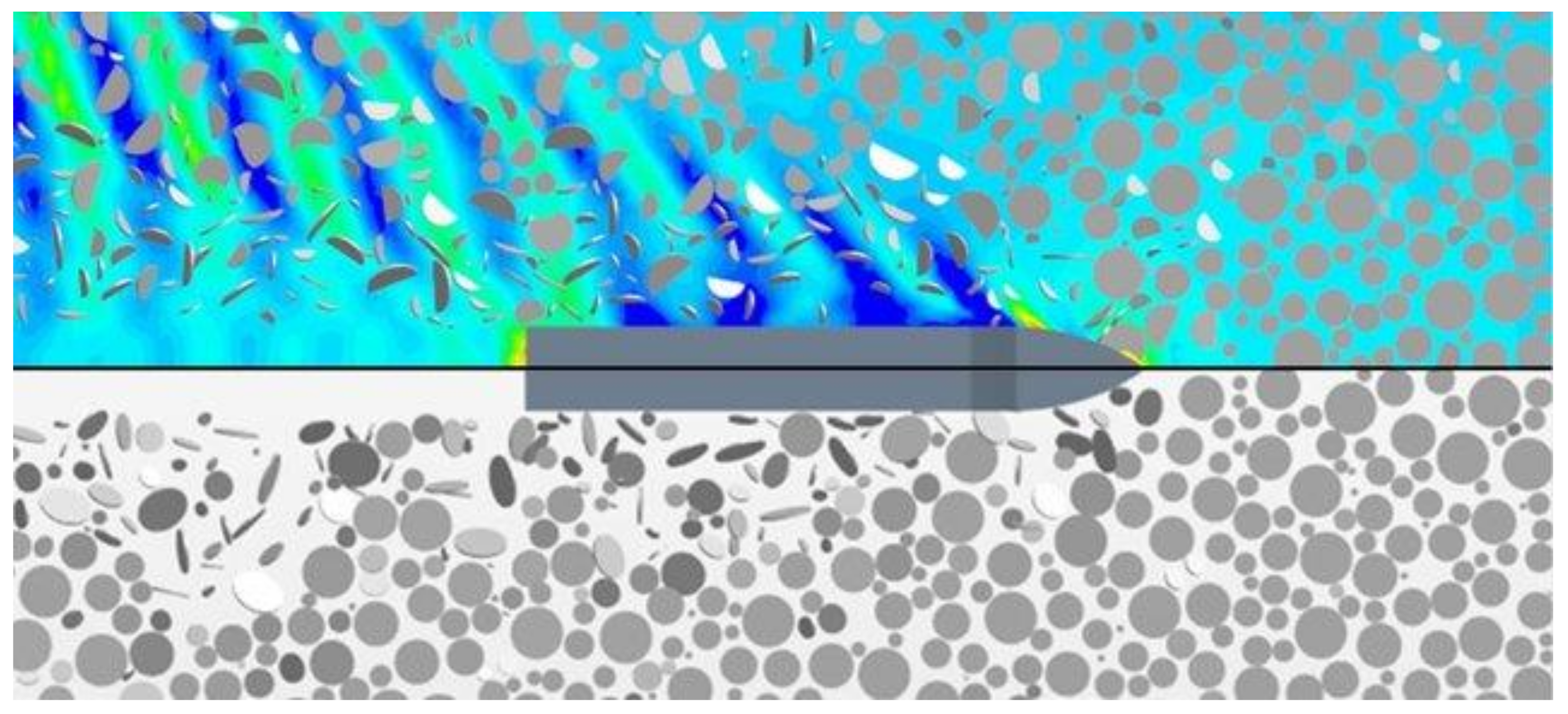
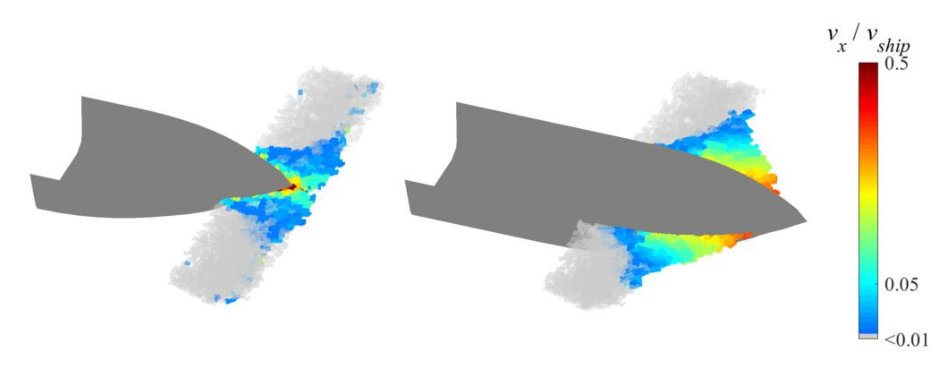
4.2. Effect of Fluid Flow

The fluid flow may affect the interaction force between a ship and broken ice through (a) inducing the motion of broken ice pieces via the ship’s wake and bow waves, (b) accelerating and damping the motion of ice, (c) affecting the stress distribution within an ice floe and hence the force limit which causes breaking, and (d) affecting the contacts between sliding ice pieces and the ship’s hull, thereby changing the total resistance. These factors affect the estimation of resistance and the local ice loads. It can be summarised that most existing models account for the effect of fluid flow with a rather simplified approach, typically with empirically added mass and drag coefficients, which are not able to reflect the ship hydrodynamics. The more complex modelling techniques include LBM and CFD. In theory, LBM is able to model a ship-induced flow. However, compared with standard CFD, LBM is much less frequently applied to ship hydrodynamic problems and still lacks validation. It has been shown that excluding fluid flows could create a non-negligible influence on the ice resistance prediction [3], as the ship flow may push the ice aside to significantly reduce the resistance. The simulation results of some models, e.g., [36], are somewhat higher than the experimental results, which is possibly due to the exclusion of the flow effect (see Figure 3). Therefore, it is suggested to couple DEM with CFD for more reliable results.
Coupling CFD with DEM will certainly increase the computational cost. However, a one-way coupling process may be used to retain the computational cost near that of using the DEM, because the CFD is computationally cheaper than the DEM. In the one-way coupling process, the CFD results influence the movement of the DEM ice particles, but the ice movement does not provide feedback to further update the CFD solution, thus the fluid field is influenced by the ship but not by the ice. As the wake attenuation in regards to ice mainly influences the ice moving away from the ship, it is deemed to have little influence on the ship performance. Thus, the one-way assumption is deemed reasonable as long as the ice concentration is not high enough to produce considerable wave reflection to further influence the ship. Mucha [54] and Luo et al. [16] compared one-way and two-way CFD+DEM simulations for ship operations in brash ice channels; both reported that using two-way coupling did not make a notable difference in ship resistance predictions. Nonetheless, this does not reject the necessity of two-way coupling for modelling other problems where the wave reflection and diffraction by ice are important, such as the propagation of ocean waves in an ice-covered zone [74,75] or ship operations in ice channels [76,77].
For models based on the NDEM, which has prioritized computational efficiency, compromises may be necessary for the consideration of computational resources. Simplified approaches such as ALE or empirical formulations provide computationally affordable solutions to account for the fluid effect. It is then suggested to define the purpose of modelling (resistance or the local ice loads) and the range of applicability (size and form of broken ice) carefully so that the deviation is still within the acceptable range. Benchmarking of the simulation results using CFD-based simulation will be helpful to quantify the deviation and add insights into the applicability of a simulator for broken ice of various forms and sizes.

4.3. Contact Modelling

It can be observed from the review that an elastic/viscoelastic contact model has been most widely adopted by the existing models, either using classical DEM or NDEM. For resistance estimation, the main uncertainty nested in such configurations is the neglection of the factor of crushing energy deviating the total energy dissipation, thereby deviating the obtained resistance. Such energy loss may be considered through setting up a restitution coefficient, but a constant restitution coefficient cannot reflect the dependence on multiple interacting factors. An investigation on the amount of crushing energy exerted when ships collide with small-size ice pieces is highly recommended. This could help in setting up a set of thresholds or contours as functions of multiple factors such as colliding speed, ice edge shape, elastic modulus, rigidity of the ship’s hull, and ice concentration, to help explain the role of crushing energy in the overall energy dissipation and decide whether simplifications in the evaluation of crushing can be made and how much deviation this allows. For example, this can be carried out by enabling and disabling a plastic limit in a simulation model, checking how much this changes the contact force when a ship collides with one ice element, and the overall resistance when a ship goes through an ice field.
From a local ice load perspective, the crushing process is always a crucial element, as it significantly determines the load length and limits the peak force. A plastic limit is necessary for the purpose of the local load estimation in ice floe fields. This has been shown to be feasible by Polojärvi et al. [42] through using classical DEM, and the simulator SAMS [12] with NDEM. In addition to that, the magnitude of the peak load is dependent on the local geometry of the contact region, e.g., the shape of ice’s contact point (round, wedge, etc.), and on the momentum transfer through the ice field, which is determined by ice-ice interaction. The idealized ice floe shapes may not be capable of mimicking the behaviour of a real ice field, highlighting the importance of modelling using realistic and more diverse ice floe shapes.

4.4. Model Validation

It can be observed that most models have been benchmarked using model-scale tests employing either refrigerated ice or synthetic ice, while comparisons with full-scale measurement are rare. Synthetic model ice is easy to produce and can correctly reflect the behaviour of rigid bodies. Refrigerated model ice is advantageous over synthetic ice due to the fact that it behaves more like real ice, allowing for crushing and cracking, and is therefore suitable to represent ice in a wider size range. More confidence can be gained through comparisons with model tests in ice basins. Nonetheless, the scalability of model ice to represent real ice, e.g., in elasticity, is not yet fully understood. Therefore, comparison with full-scale tests should always be given priority if quality data are available from polar voyages.
The main issue associated with full-scale tests is the difficulty of measuring the ice parameters correctly, especially for brash ice channels and ice ridges where the profile of the ice rubble is difficult to obtain. For these ice conditions, model tests using refrigerated ice still represent the best source of validation. A remaining issue is the determination of the ice-ice frictional coefficient, which has been shown to have a major effect on the estimated resistance, but which is rarely measured.
Validation using a model-scale test is also recommended for the simulation of sliding ice pieces after level ice breaking, as presawn ice can be easily cut with size parameters well under control. For an ice floe field, modern image analysis techniques have made it possible to rebuild the ice field digitally while maintaining high similarity to the original ice field [78,79]. Validation using available full-scale test data (e.g., [80]) can provide more evidence of the accuracy of existing methods for floe ice navigation, while validation with model test data (e.g., [81]) provides supplementary evidence on the dependence of resistance on factors such as floe size, ship speed, ice thickness, and concentration.

5. Conclusions

This paper has reviewed simulation models for various interactions between a ship and broken ice. The following conclusions can be drawn based on the review.
  • To date, the major computational models created to investigate a ship’s interactions with broken ice have focused on a ship’s interaction with ice floes. There are certain studies on the interaction with brash ice, but ridged ice and sliding ice pieces have received little attention despite their importance in a ships’ ice-going capability. More computational investigations on ridged ice and sliding ice pieces are required to fully understand these processes.
  • Most models of ship interactions with ice floes are created for resistance estimation, while only a few works have addressed local ice loads. More future research is suggested on the estimation of local loads, which serves as a structural safety evaluation, especially in the context of merchant ships traveling through the Arctic region.
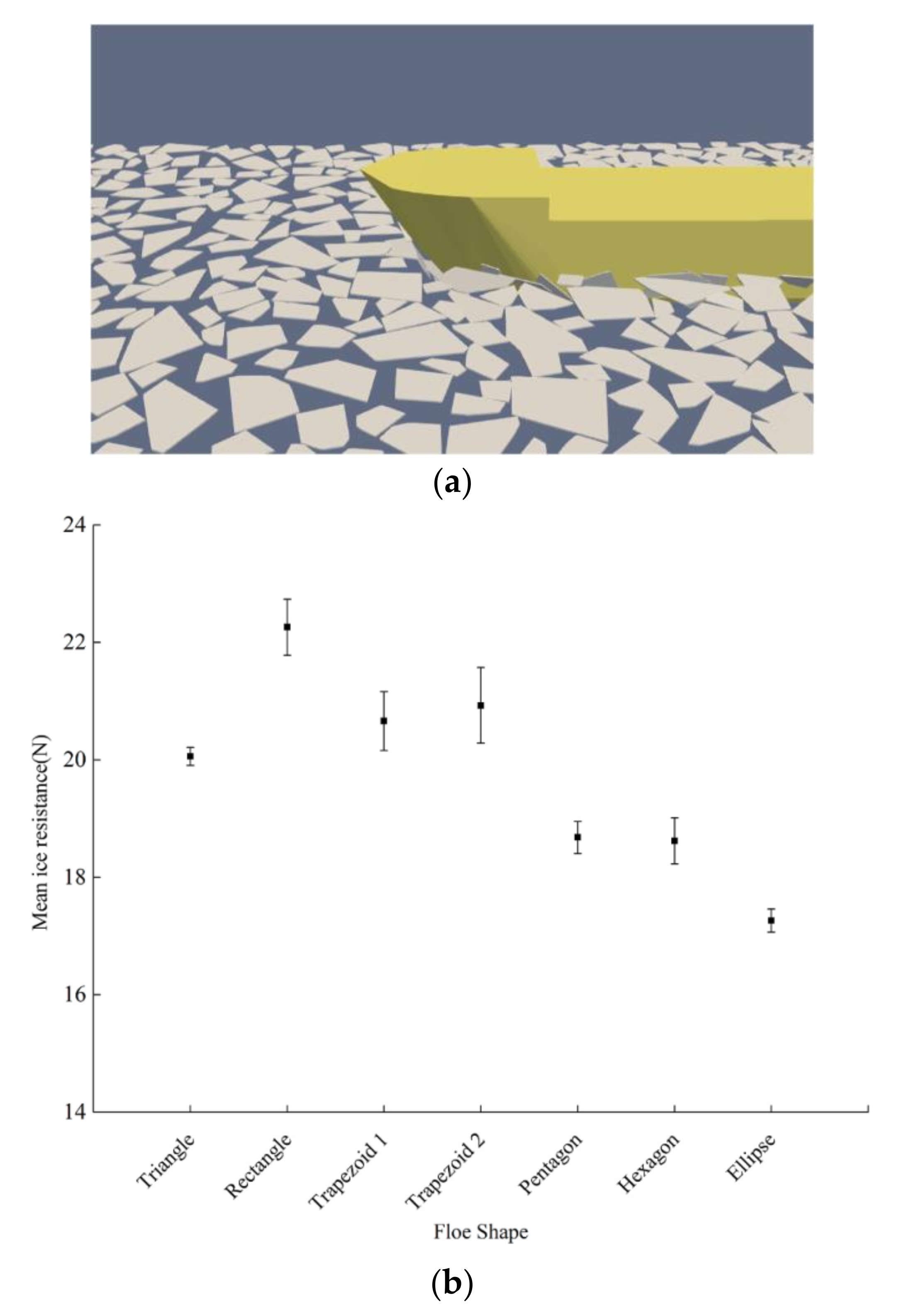
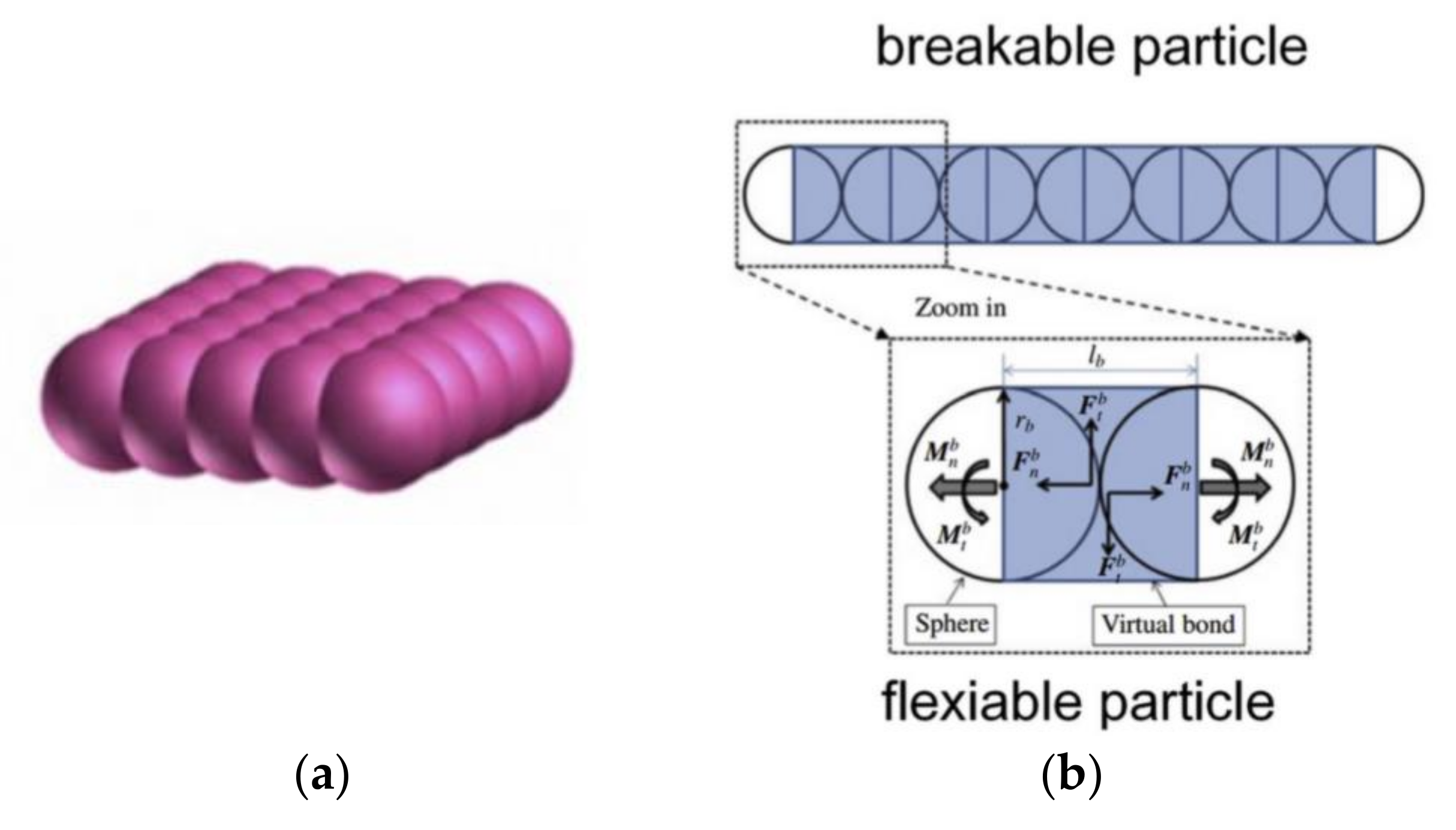
  • Most models assume ice to be unbreakable, making them suitable for modelling broken ice only up to a certain size. Introducing a cracking mechanism can widen the range of applicability of the existing models. For example, this could be achieved by using clumped DEM particles.
  • The role of crushing during a ship’s interaction with small-sized broken ice is recommended for investigation in future work. Many models simplify this process by defining it as elastic contacts due to the complexity of modelling, but the effect of small ice-piece crushing on ice resistance estimations has yet to be thoroughly clarified.
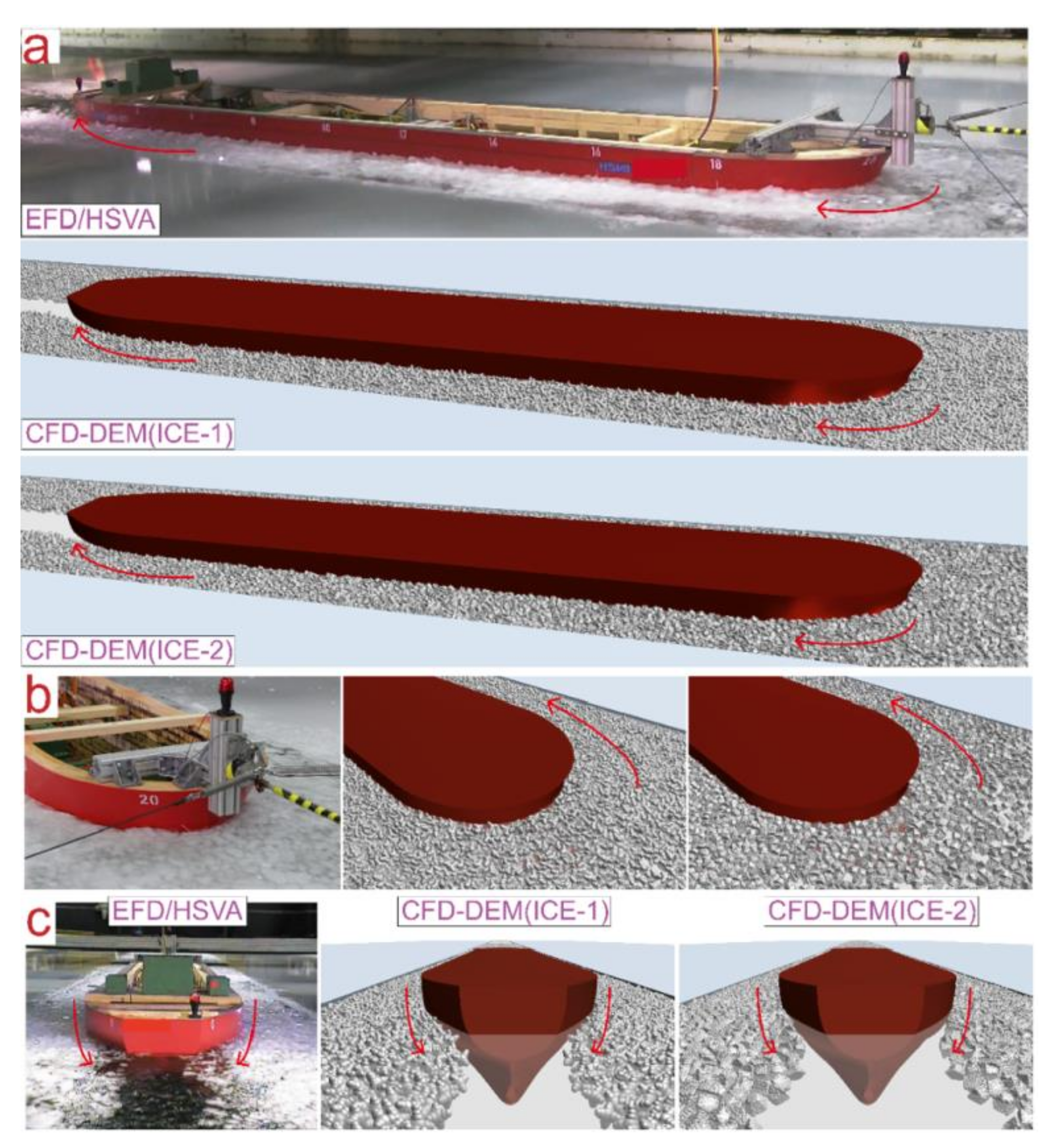
  • The majority of existing models simplify the hydrodynamic force as drag and added mass, which deviates the estimation, especially when ship wakes play a big role in the movement of broken ice. Coupling between DEM and CFD offers good potential for dealing with the factor of broken ice interaction with ships. CFD gives good indications of the wake variation versus the ship speed, which is what the ship-associated flow mainly depends on. With a widespread reduction of the extent, thickness, and compactness of sea ice, hydrodynamics is expected to be increasingly important for studying ship-ice interactions. Therefore, further development and validation of CFD-based methods are particularly recommended.

Author Contributions

Conceptualization, F.L. and L.H.; methodology, F.L. and L.H; formal analysis, F.L. and L.H.; investigation, F.L. and L.H.; resources, F.L. and L.H.; writing—original draft preparation, F.L. and L.H.; writing—review and editing, F.L. and L.H. All authors have read and agreed to the published version of the manuscript.

Funding

This research received no external funding.

Institutional Review Board Statement

Not applicable.

Informed Consent Statement

Not applicable.

Conflicts of Interest

The authors declare no conflict of interest.

References

  1. Gong, H.; Polojärvi, A.; Tuhkuri, J. Discrete element simulation of the resistance of a ship in unconsolidated ridges. Cold Reg. Sci. Technol. 2019, 167, 102855. [Google Scholar] [CrossRef]
  2. Sazidy, M. Development of Velocity Dependent Ice Flexural Failure Model and Application to Safe Speed. Ph.D. Thesis, Memorial University of Newfoundland, St. John’s, NL, Canada, 2015. [Google Scholar]
  3. Huang, L.; Tuhkuri, J.; Igrec, B.; Li, M.; Stagonas, D.; Toffoli, A.; Cardiff, P.; Thomas, G. Ship resistance when operating in floating ice floes: A combined CFD&DEM approach. Mar. Struct. 2020, 74, 102817. [Google Scholar] [CrossRef]
  4. Keijdener, C.; Hendrikse, H.; Metrikine, A. The effect of hydrodynamics on the bending failure of level ice. Cold Reg. Sci. Technol. 2018, 153, 106–119. [Google Scholar] [CrossRef]
  5. Lindqvist, G. A straightforward method for calculation of ice resistance of ships. In Proceedings of the 10th International Conference on Port and Ocean Engineering under Arctic Conditions, Luleå, Sweden, 12–16 June 1989; pp. 722–735. [Google Scholar]
  6. Riska, K.; Wilhelmson, M.; Englund, K.; Leiviskä, T. Performance of Merchant Vessels in Ice in the Baltic; Research Report No. 52; Ship Laboratory, Helsinki University of Technology: Espoo, Finland, 1997. [Google Scholar]
  7. Malmberg, S. Omfartygs Fastkling i is (of Ship’s Becoming Beset in Ice). Master’s Thesis, Helsinki University of Technology, Espoo, Finland, 1983. [Google Scholar]
  8. Aboul-Azm, A. Ship Resistance in Ice Floe Covered Waters; Memorial University of Newfoundland: St. John’s, NL, Canada, 1989. [Google Scholar]
  9. Tuhkuri, J.; Polojärvi, A. A review of discrete element simulation of ice-structure interaction. Philos. Trans. R. Soc. A Math. Phys. Eng. Sci. 2018, 376, 20170335. [Google Scholar] [CrossRef] [PubMed] [Green Version]
  10. Ji, S.; Li, Z.; Li, C.; Shang, J. Discrete element modeling of ice loads on ship and offshore structures. Acta Oceanol. Sin. 2013, 188, 45–54. [Google Scholar] [CrossRef] [Green Version]
  11. Daley, C.; Alawneh, S.; Peters, D.; Quinton, B.; Colbourne, B. GPU modeling of ship operations in pack ice. In Proceedings of the International Conference and Exhibition on Performance of Ships and Structures in Ice, Banff, AB, Canada, 17–20 September 2012; pp. 122–127. [Google Scholar]
  12. Lubbad, R.; Løset, S.; Lu, W.; Tsarau, A.; van den Berg, M. Simulator for Arctic Marine Structures (SAMS). In Proceedings of the ASME 2018 37th International Conference on Ocean, Offshore and Arctic Engineering (OMAE2018), Madrid, Spain, 17–22 June 2018. [Google Scholar] [CrossRef] [Green Version]
  13. Sawamura, J. 2D numerical modeling of icebreaker advancing in ice-covered water. Int. J. Nav. Archit. Ocean Eng. 2018, 10, 385–392. [Google Scholar] [CrossRef]
  14. Guo, C.Y.; Zhang, Z.T.; Tian, T.P.; Li, X.Y.; Zhao, G.D. Numerical Simulation on the Resistance Performance of Ice-Going Container Ship Under Brash Ice Conditions. China Ocean Eng. 2018, 32, 546–556. [Google Scholar] [CrossRef]
  15. Wang, C.; Hu, X.; Tian, T.; Guo, C.; Wang, C. Numerical simulation of ice loads on a ship in broken ice fields using an elastic ice model. Int. J. Nav. Archit. Ocean Eng. 2020, 12, 414–427. [Google Scholar] [CrossRef]
  16. Luo, W.; Jiang, D.; Wu, T.; Guo, C.; Wang, C.; Deng, R.; Dai, S. Numerical simulation of an ice-strengthened bulk carrier in brash ice channel. Ocean Eng. 2020, 196, 106830. [Google Scholar] [CrossRef]
  17. Islam, M.; Mills, J.; Gash, R.; Pearson, W. A literature survey of broken ice-structure interaction modelling methods for ships and offshore platforms. Ocean Eng. 2021, 221, 108527. [Google Scholar] [CrossRef]
  18. Xue, Y.; Liu, R.; Li, Z.; Han, D. A review for numerical simulation methods of ship–ice interaction. Ocean Eng. 2020, 215, 107853. [Google Scholar] [CrossRef]
  19. Metrikin, I.; Løset, S.; Jenssen, N.A.; Kerkeni, S. Numerical simulation of dynamic positioning in ice. Mar. Technol. Soc. J. 2013, 47, 14–30. [Google Scholar] [CrossRef] [Green Version]
  20. Aarsæther, K.G.; Su, B.; Kristiansen, D. Numerical study of a fishing vessel operating in partially ice covered waters. Proc. Int. Conf. Offshore Mech. Arct. Eng. OMAE 2018, 8, 1–8. [Google Scholar] [CrossRef]
  21. Liu, L.; Ji, S. Ice load on floating structure simulated with dilated polyhedral discrete element method in broken ice field. Appl. Ocean Res. 2018, 75, 53–65. [Google Scholar] [CrossRef]
  22. Popov, Y.N.; Faddeev, O.V.; Kheisin, D.E.; Yakovlev, A.A. Strength of Ships Sailing in Ice. Army foreign science and technology Centre: Charlottesville, VA, USA, 1969; Available online: https://apps.dtic.mil/sti/citations/AD0684596 (accessed on 26 December 2021).
  23. Riska, K. On the Mechanics of the Ramming Interaction Between a Ship and a Massive Ice Floe. Ph.D. Thesis, Helsinki University of Technology, Espoo, Finland, 1987. [Google Scholar] [CrossRef]
  24. Lu, W.; Lubbad, R.; Løset, S. In-plane fracture of an ice floe: A theoretical study on the splitting failure mode. Cold Reg. Sci. Technol. 2015, 110, 77–101. [Google Scholar] [CrossRef]
  25. Lu, W.; Lubbad, R.; Løset, S. Out-of-plane failure of an ice floe: Radial-crack-initiation-controlled fracture. Cold Reg. Sci. Technol. 2015, 119, 183–203. [Google Scholar] [CrossRef]
  26. Lu, W.; Lubbad, R.; Løset, S.; Kashafutdinov, M. Fracture of an ice floe: Local out-of-plane flexural failures versus global in-plane splitting failure. Cold Reg. Sci. Technol. 2016, 123, 1–13. [Google Scholar] [CrossRef]
  27. Fournier, N. Sea Ice Type Classification for Ship Performance Modelling; MET Office: Bristol, UK, 2019; Available online: www.sedna-project.eu (accessed on 26 December 2021).
  28. Daley, C.; Alawneh, S.; Peters, D.; Colbourne, B. GPU-Event-Mechanics evaluation of ice impact load statistics. In Proceedings of the Arctic Technology Conference, Houston, TX, USA, 10–12 February 2014. [Google Scholar]
  29. TRAFI Maritime Safety Regulation. Ice Class Regulations and the Application Thereof. TRAFI/494131/03.04.01.00/2016; TRAFICOM: Helsinki, Finland, 2010; Available online: https://www.traficom.fi/en/transport/maritime/ice-classes-ships (accessed on 26 December 2021).
  30. Li, F.; Suominen, M.; Lu, L.; Kujala, P.; Taylor, R. A probabilistic method for long-term estimation of ice loads on ship hull. Struct. Saf. 2021, 93, 102130. [Google Scholar] [CrossRef]
  31. Thomson, J.; Ackley, S.; Girard-Ardhuin, F.; Ardhuin, F.; Babanin, A.; Boutin, G.; Brozena, J.; Cheng, S.; Collins, C.; Doble, M.; et al. Overview of the Arctic Sea State and Boundary Layer Physics Program. J. Geophys. Res. Ocean. 2018, 123, 8674–8687. [Google Scholar] [CrossRef]
  32. Huang, L.; Li, Z.; Ryan, C.; Ringsberg, J.W.; Pena, B.; Li, M.; Ding, L.; Thomas, G. Ship resistance when operating in floating ice floes: Derivation, validation, and application of an empirical equation. Mar. Struct. 2021, 79, 103057. [Google Scholar] [CrossRef]
  33. Li, Z.; Ryan, C.; Huang, L.; Ding, L.; Ringsberg, J.W.; Thomas, G. A comparison of two ship performance models against full-scale measurements on a cargo ship on the Northern Sea Route. Ships Offshore Struct. 2021, 16, 237–244. [Google Scholar] [CrossRef]
  34. Ryan, C.; Huang, L.; Li, Z.; Ringsberg, J.W.; Thomas, G. An Arctic ship performance model for sea routes in ice-infested waters. Appl. Ocean Res. 2021, 117, 102950. [Google Scholar] [CrossRef]
  35. Kim, H.; Im, N.; Sawamura, J. Experimental and numerical investigation of ship-ice interactions in pack ice. In Proceedings of the International Conference on Port and Ocean Engineering under Arctic Conditions, Busan, Korea, 11–16 June 2017. [Google Scholar]
  36. Yang, B.; Sun, Z.; Zhang, G.; Wang, Q.; Zong, Z.; Li, Z. Numerical estimation of ship resistance in broken ice and investigation on the effect of floe geometry. Mar. Struct. 2021, 75, 102867. [Google Scholar] [CrossRef]
  37. Lau, M.; Lawrence, K.P.; Rothenburg, L. Discrete element analysis of ice loads on ships and structures. Ships Offshore Struct. 2011, 6, 211–221. [Google Scholar] [CrossRef] [Green Version]
  38. Zhan, D.; Agar, D.; He, M.; Spencer, D.; Molyneux, D. Numerical simulation of ship maneuvering in pack ice. Proc. Int. Conf. Offshore Mech. Arct. Eng. OMAE 2010, 4, 855–862. [Google Scholar] [CrossRef]
  39. McKenna, R.; Spencer, D.; Lau, M.; Walker, D.; Crocker, G. Modeling the forces exerted by pack ice consisting of small floes. In Proceedings of the International Conference on Offshore Mechanics and Arctic Engineering, Yokohama, Japan, 13–17 April 1997; pp. 320–338. [Google Scholar]
  40. Paavilainen, J.; Tuhkuri, J.; Polojärvi, A. 2D numerical simulations of ice rubble formation process against an inclined structure. Cold Reg. Sci. Technol. 2011, 68, 20–34. [Google Scholar] [CrossRef]
  41. Polojärvi, A.; Tuhkuri, J. 3D discrete numerical modelling of ridge keel punch through tests. Cold Reg. Sci. Technol. 2009, 56, 18–29. [Google Scholar] [CrossRef]
  42. Polojärvi, A.; Gong, H.; Tuhkuri, J. Comparison of Full-scale and DEM simulation Data on Ice Loads Due to Floe Fields on a Ship Hull. In Proceedings of the 26th International Conference on Port and Ocean Engineering under Arctic Conditions, Moscow, Russia, 14–18 June 2021. [Google Scholar]
  43. Wang, J.; Derradji-Aouat, A. Ship Performance in Broken Ice Floes—Preliminary Numerical Simulations; Institute for Ocean Technology, National Research Council: St. John’s, NL, Canada, 2010. [Google Scholar] [CrossRef]
  44. Kim, M.-C.; Lee, S.-K.; Lee, W.-J.; Wang, J. Numerical and experimental investigation of the resistance performance of an icebreaking cargo vessel in pack ice conditions. Int. J. Nav. Archit. Ocean Eng. 2013, 5, 116–131. [Google Scholar] [CrossRef] [Green Version]
  45. Kim, J.H.; Kim, Y.; Kim, H.S.; Jeong, S.Y. Numerical simulation of ice impacts on ship hulls in broken ice fields. Ocean Eng. 2019, 182, 211–221. [Google Scholar] [CrossRef]
  46. Guo, W.; Zhao, Q.S.; Tian, Y.K.; Zhang, C.W. Research on total resistance of ice-going ship for different floe ice distributions based on virtual mass method. Int. J. Nav. Archit. Ocean Eng. 2020, 12, 957–966. [Google Scholar] [CrossRef]
  47. Janßen, C.F.; Mierke, D.; Rung, T. On the development of an efficient numerical ice tank for the simulation of fluid-ship-rigid-ice interactions on graphics processing units. Comput. Fluids 2017, 155, 22–32. [Google Scholar] [CrossRef]
  48. van den Berg, M.; Lubbad, R.; Løset, S. An implicit time-stepping scheme and an improved contact model for ice-structure interaction simulations. Cold Reg. Sci. Technol. 2018, 155, 193–213. [Google Scholar] [CrossRef]
  49. Lubbad, R.; Løset, S. A numerical model for real-time simulation of ship–ice interaction. Cold Reg. Sci. Technol. 2011, 65, 111–127. [Google Scholar] [CrossRef] [Green Version]
  50. Jou, O.; Celigueta, M.A.; Latorre, S.; Arrufat, F.; Oñate, E. A bonded discrete element method for modeling ship–ice interactions in broken and unbroken sea ice fields. Comput. Part. Mech. 2019, 6, 739–765. [Google Scholar] [CrossRef]
  51. Han, Y.; Sawamura, J. Fatigue damage calculation for ship hulls operating in pack ice. In Proceedings of the International Conference on Port and Ocean Engineering under Arctic Conditions, Busan, Korea, 11–16 June 2017. [Google Scholar]
  52. Liu, R.W.; Xue, Y.Z.; Lu, X.K.; Cheng, W.X. Simulation of ship navigation in ice rubble based on peridynamics. Ocean Eng. 2018, 148, 286–298. [Google Scholar] [CrossRef]
  53. Konno, A. Resistance evaluation of ship navigation in brash ice channels with physically based modeling. In Proceedings of the International Conference on Port and Ocean Engineering under Arctic Conditions, Lulea, Sweden, 9–12 June 2009; Volume 2, pp. 855–863. [Google Scholar]
  54. Mucha, P. Fully-coupled CFD-DEM for simulations of ships advancing through brash ice. In Proceedings of the SNAME Maritime Convention, Tacoma, DC, USA, 30 October–1 November 2019; Volume 1. [Google Scholar]
  55. Sorsimo, A.; Nyman, T.; Heinonen, J.; Transport, F.; Agency, S.; Agency, F.T. Ship-Ice Interaction in a Channel; Finnish Transport Safety Agency: Helsinki, Finland, 2016; Available online: https://arkisto.trafi.fi/filebank/a/1477641190/49e5c4fcfde337028da9f4487ba670c2/22897-WNRB_research_report_93.pdf (accessed on 26 December 2021).
  56. Prasanna, M.; Hisette, Q. Discrete Element Simulation of Ships Navigating Through Brash Ice Channels. In Proceedings of the OTC Arctic Technology Conference, Houston, TX, USA, 5–7 November 2018. [Google Scholar] [CrossRef]
  57. Vroegrijk, E.A.J. Application of the Discrete Element Method (DEM) on ship-ice interaction. In Proceedings of the International Conference and Exhibition on Performance of Ships and Structures in Ice 2012, ICETECH 2012, Banff, AB, Canada, 17–20 September 2012; pp. 128–132. [Google Scholar]
  58. Vroegrijk, E. Validation of CFD+DEM against measured data. In Proceedings of the International Conference on Offshore Mechanics and Arctic Engineering—OMAE, St. John’s, NL, Canada, 31 May–5 June 2015; 2015; Volume 8, pp. 1–7. [Google Scholar] [CrossRef]
  59. Karulin, B.E. Simulation of ridge keel behaviour in direct shear and punch tests by discrete element method. In Proceedings of the 16th IAHR International Symposium on Ice, Dunedin, New Zealand, 2–6 December 2002; Volume 2002, pp. 143–151. [Google Scholar]
  60. Yulmetov, R.; Bailey, E.; Ralph, F. A discrete element model of ice ridge interaction with a conical structure. In Proceedings of the International Conference on Port and Ocean Engineering under Arctic Conditions (POAC 2017), Busan, Korea, 11–16 June 2017. [Google Scholar]
  61. Gong, H. Discrete-Element Modelling of Ship Interaction with Unconsolidated Ice Ridges: Ridge Resistance and Failure Behaviour. Ph.D. Thesis, Aalto University, Espoo, Finland, 2021. [Google Scholar]
  62. Hisette, Q.; Alekseev, A.; Seidel, J. Discrete element simulation of ship breaking through ice ridges. In Proceedings of the International Offshore and Polar Engineering Conference, San Francisco, CA, USA, 25–30 June 2017; pp. 1401–1409. [Google Scholar]
  63. Wang, F.; Zhou, L.; Zou, Z.J.; Song, M.; Wang, Y.; Liu, Y. Study of continuous icebreaking process with cohesive element method. Brodogradnja 2019, 70, 93–114. [Google Scholar] [CrossRef]
  64. Resistance tests in Ice. ITTC Recommended Procedures and Guidelines; The International Towing Tank Conference: Zürich, Switzerland, 2017; Available online: https://www.ittc.info/media/8053/75-02-04-021.pdf (accessed on 26 December 2021).
  65. Konno, A.; Mizuki, T. Numerical Simulation of Pre-sawn Ice Test of Model Icebreaker Using Physically Based Modeling. In Proceedings of the 18th IAHR International Symposium on Ice, Sapporo, Japan, 28 August–1 September 2006; pp. 17–23. [Google Scholar]
  66. Sawamura, J.; Tachibana, T. Development of a Numerical Simulation for Rotating and Sliding of the Ice Floes Along a Ship Hull. In Proceedings of the Port and Ocean Engineering under Arctic Conditions, Montreal, QC, Canada, 10–14 July 2011. [Google Scholar]
  67. Sawamura, J.; Kioka, S.; Konno, A. Experimental and numerical investigation on ice submerging for icebreaker with 2D model test using synthetic ice. In Proceedings of the 23rd International Conference on Port and Ocean Engineering under Arctic Conditions (POAC ‘15), Trondheim, Norway, 14–18 June 2015. [Google Scholar]
  68. Puntigliano, F. On the Resistance Components below the Waterline in the Continuous Mode of Icebreaking: Model Tests; Hamburgische Schiffbau-Versuchsanst: Hamburg, Germany, 1995. [Google Scholar]
  69. Kämäräinen, J. Theoretical Investigation on the Effect of Fluid Flow between the Hull of a Ship and Ice Floes on Ice Resistance in Level Ice. Ph.D. Thesis, Helsinki University of Technology, Espoo, Finland, 2007. [Google Scholar]
  70. Li, F.; Goerlandt, F.; Kujala, P. Numerical simulation of ship performance in level ice: A framework and a model. Appl. Ocean Res. 2020, 102, 102288. [Google Scholar] [CrossRef]
  71. Xu, Y.; Kujala, P.; Hu, Z.; Li, F.; Chen, G. Numerical simulation of level ice impact on landing craft bow considering the transverse isotropy of Baltic Sea ice based on XFEM. Mar. Struct. 2020, 71, 102735. [Google Scholar] [CrossRef]
  72. Liu, L.; Ji, S. Bond and fracture model in dilated polyhedral DEM and its application to simulate breakage of brittle materials. Granul. Matter 2019, 21, 41. [Google Scholar] [CrossRef]
  73. Zhong, W.; Yu, A.; Liu, X.; Tong, Z.; Zhang, H. DEM/CFD-DEM Modelling of Non-spherical Particulate Systems: Theoretical Developments and Applications. Powder Technol. 2016, 302, 108–152. [Google Scholar] [CrossRef]
  74. Huang, L.; Ren, K.; Li, M.; Tuković, Ž.; Cardiff, P.; Thomas, G. Fluid-structure interaction of a large ice sheet in waves. Ocean Eng. 2019, 182, 102–111. [Google Scholar] [CrossRef] [Green Version]
  75. Bennetts, L.; Royal, T.W.-P. Water wave transmission by an array of floating discs. Proc. R. Soc. A Math. Phys. Eng. Sci. 2015, 471, 20140698. [Google Scholar] [CrossRef] [Green Version]
  76. Huang, L.; Li, M.; Romu, T.; Dolatshah, A.; Thomas, G. Simulation of a ship operating in an open-water ice channel. Ships Offshore Struct. 2021, 16, 353–362. [Google Scholar] [CrossRef]
  77. Li, F.; Suominen, M.; Kujala, P. Ship performance in ice channels narrower than ship beam: Model test and numerical investigation. Ocean Eng. 2021, 240, 109922. [Google Scholar] [CrossRef]
  78. Zhang, Q.; Skjetne, R. Image processing for identification of sea-ice floes and the floe size distributions. IEEE Trans. Geosci. Remote Sens. 2015, 53, 2913–2924. [Google Scholar] [CrossRef]
  79. Li, F.; Khawar, M.; Sandru, A.; Lu, L.; Suominen, M.; Kujala, P. Full-scale measurement of ship performance and ice loads in Antarctic ice floe fields. In Proceedings of the Port and Ocean Engineering under Arctic Conditions, Moscow, Russia, 14–18 June 2021. [Google Scholar]
  80. Li, F.; Lu, L.; Suominen, M.; Kujala, P. Short-term statistics of ice loads on ship bow frames in floe ice fields: Full-scale measurements in the Antarctic ocean. Mar. Struct. 2021, 80, 103049. [Google Scholar] [CrossRef]
  81. Jeong, S.Y.; Choi, K.; Kim, H.S. Investigation of ship resistance characteristics under pack ice conditions. Ocean Eng. 2021, 219, 108264. [Google Scholar] [CrossRef]
Figure 1. Various forms of broken ice: (a) a brash ice channel, (b) an ice ridge, (c) sliding ice pieces under an advancing ship during a model-scale test, and (d) an ice floe field (Figure sources: (a,c,d) are from the first author, (b) is from [1]).
Jmse 10 00165 g001
Figure 2. A sketch showing local load identification, the blue region denoting the contact area obtained from a simulation.
Jmse 10 00165 g002
Figure 3. The CFD+DEM coupled simulation of a ship in a pancake ice field [3] showing a ship advancing in ice floes with and without the wake effect. It can be seen that the waves can push the floes away from the hull, but when the waves are eliminated, the floes slide closely along the hull and present more contacts.
Jmse 10 00165 g003
Figure 4. The simulation of a ship in an ice floe field with different shapes and the effect of floe shape on mean ice resistance [36]: (a) simulation screenshot; (b) resistance for different ice shapes.
Jmse 10 00165 g004
Figure 5. The bending and splitting failure of a finite-size ice floe from simulation [13].
Jmse 10 00165 g005
Figure 6. The comparison of brash ice movement results from a model test and from a CFD+DEM coupled simulation [16].
Jmse 10 00165 g006
Figure 7. A DEM simulation of a ship penetrating a narrow ice ridge [61].
Jmse 10 00165 g007
Figure 8. A model ship towed through presawn ice at the Aalto ice tank (photo taken by the first author).
Jmse 10 00165 g008
Figure 9. A theoretical view of the methodology for breakable DEM particles [73]: (a) clumped; (b) DEM particles illustration showing breaking up.
Jmse 10 00165 g009
Table 1. The summary of models of a ship advancing in floe ice fields.
Contact ModelFloe ShapeFluid FlowCrackingValidation
Huang et al. [3]ViscoelasticCircular diskCFDNoModel test with synthetic ice; full-scale measurement
Ji et al. [10]ViscoelasticCircular diskEmpiricalNoNo
Kim et al. [35]ViscoelasticCircular diskEmpiricalNoModel test with synthetic ice
Yang et al. [36]ImpulsePolygonEmpiricalNoModel test with synthetic ice
DECICEViscoelasticPolygonEmpiricalNoModel test with refrigerated ice
Polojarvi et al. [42]Elastic-viscous-plasticSquareEmpiricalNoFull-scale measurement
Wang and Derradij-Aouat [43]ElasticSquareALENoModel test with refrigerated ice
Kim et al. [44]ElasticTriangleALENoModel test with refrigerated ice and synthetic ice
Guo et al. [14]ElasticSquareALENoModel test with synthetic ice
Wang et al. [15]ElasticSquareALENoModel test with synthetic ice
Kim et al. [45]ElasticPolygonEmpiricalNoModel test with refrigerated ice
Guo et al. [46]ViscoelasticSquareEmpiricalNoModel test with synthetic ice
Janßen et al. [47]ImpulseRandomLBMNoNo
GEMPlasticPolygonEmpiricalYes 1Full-scale measurement
SAMSElastic-viscous-plasticPolygonEmpiricalYesFull-scale measurement
Jou et al. [50]ViscoelasticRectangleNoYesNo
Sawamura [13]ImpulseRectangleEmpiricalYesNo
Liu et al. [52]ElasticPolygonNoYesNo
1 Not yet published.
Table 2. The summary of models of a ship advancing in a brash ice channel, ridged ice, and sliding ice pieces.
Contact ModelFloe ShapeFluid FlowValidation
Models for the brash ice channel
Konno [53]ImpulseSpherical and cubicEmpiricalNo
Mucha [54]ViscoelasticPolyhedralCFDNo
Luo et al. [16]ViscoelasticTetrahedral and irregular polyhedralCFDModel test with refrigerated ice
Sorsimo et al. [55]ElasticSphericalEmpiricalNo
Prasanna [56]ElasticSphericalEmpiricalModel test with refrigerated ice
Vroegrijk [57]ViscoelasticSphericalCFDFull-scale measurement
Models for ridged ice
Gong et al. [1,61]ViscoelasticCubicEmpiricalNo
Hisette et al. [62]ElasticCubicEmpiricalModel test with refrigerated ice
Models for sliding ice pieces
Konno and Mizuki [65]ImpulseCubicEmpiricalNo
Sawamura [66]ImpulseCubicEmpiricalModel test with synthetic ice
Publisher’s Note: MDPI stays neutral with regard to jurisdictional claims in published maps and institutional affiliations.

