
Finite Element Modelling on the Mechanical Behaviour of Marine Bonded Composite Hose (MBCH) under Burst and Collapse

 ,
, 


Abstract
1. Introduction
2. Materials and Methods
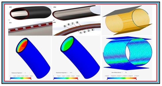
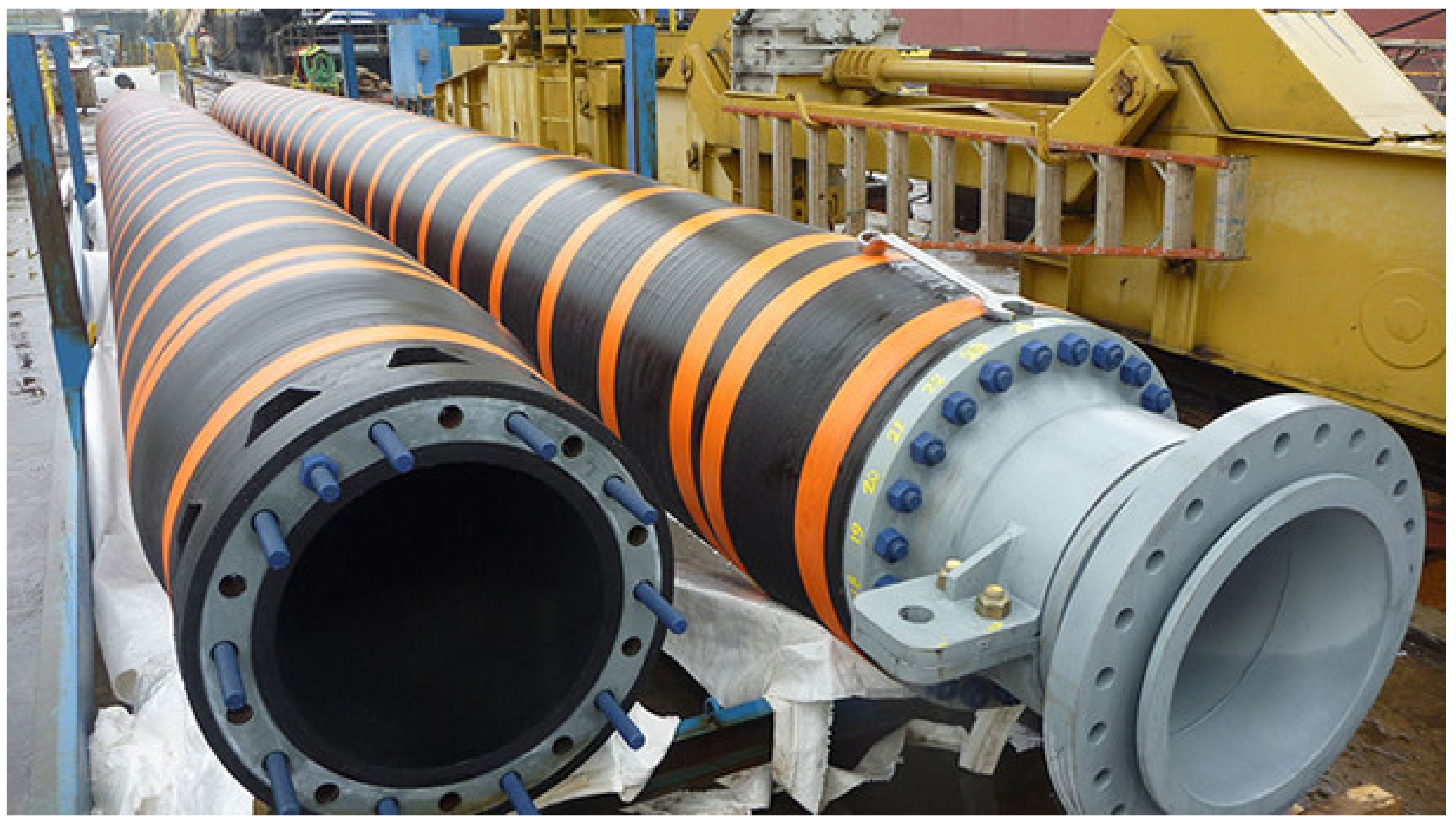
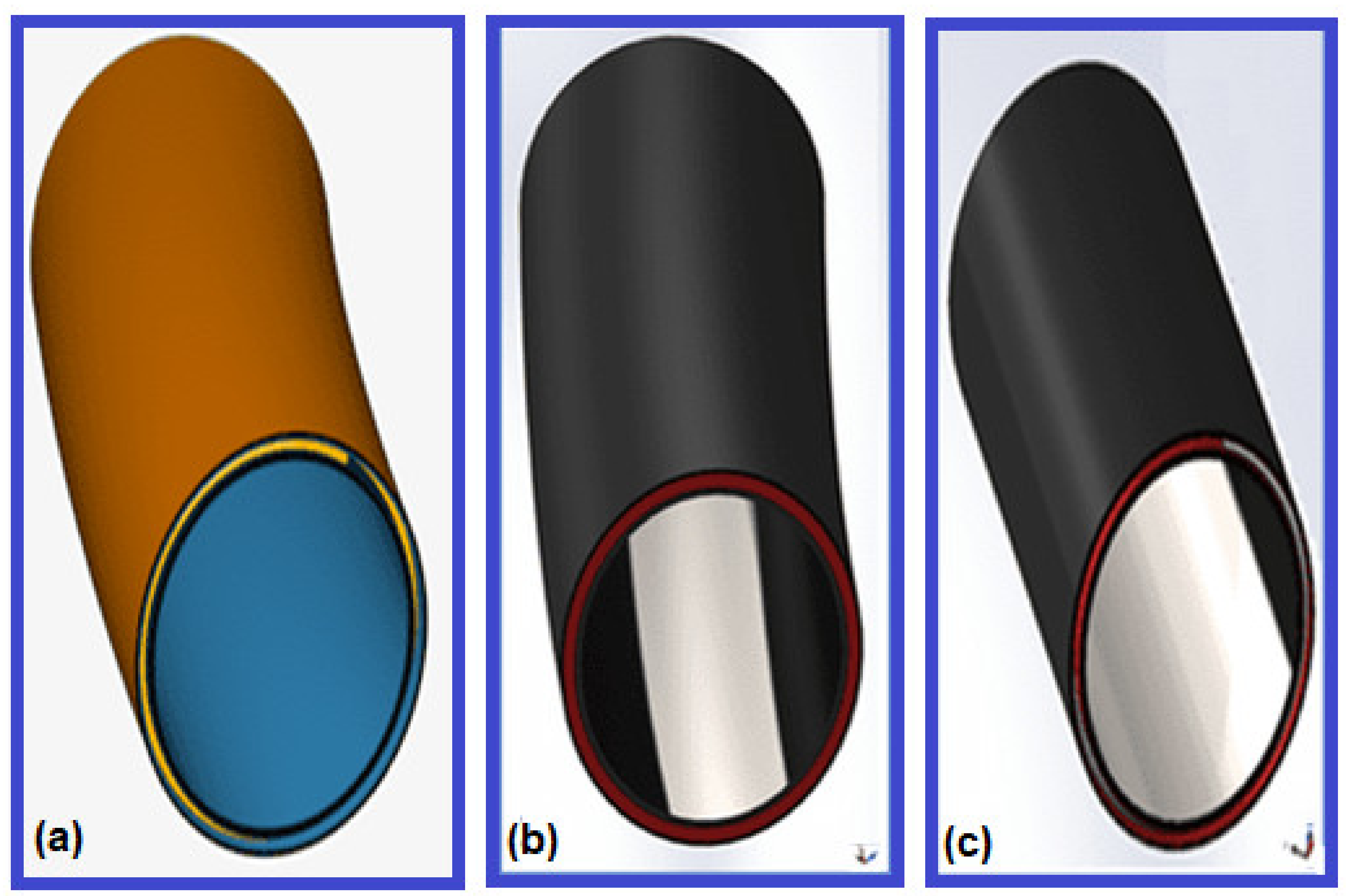
2.1. Model Description
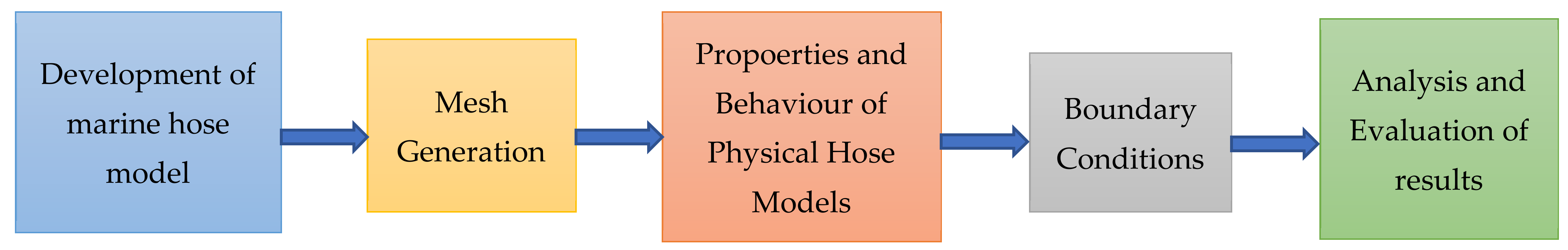
2.2. Methodology
2.3. Material Properties
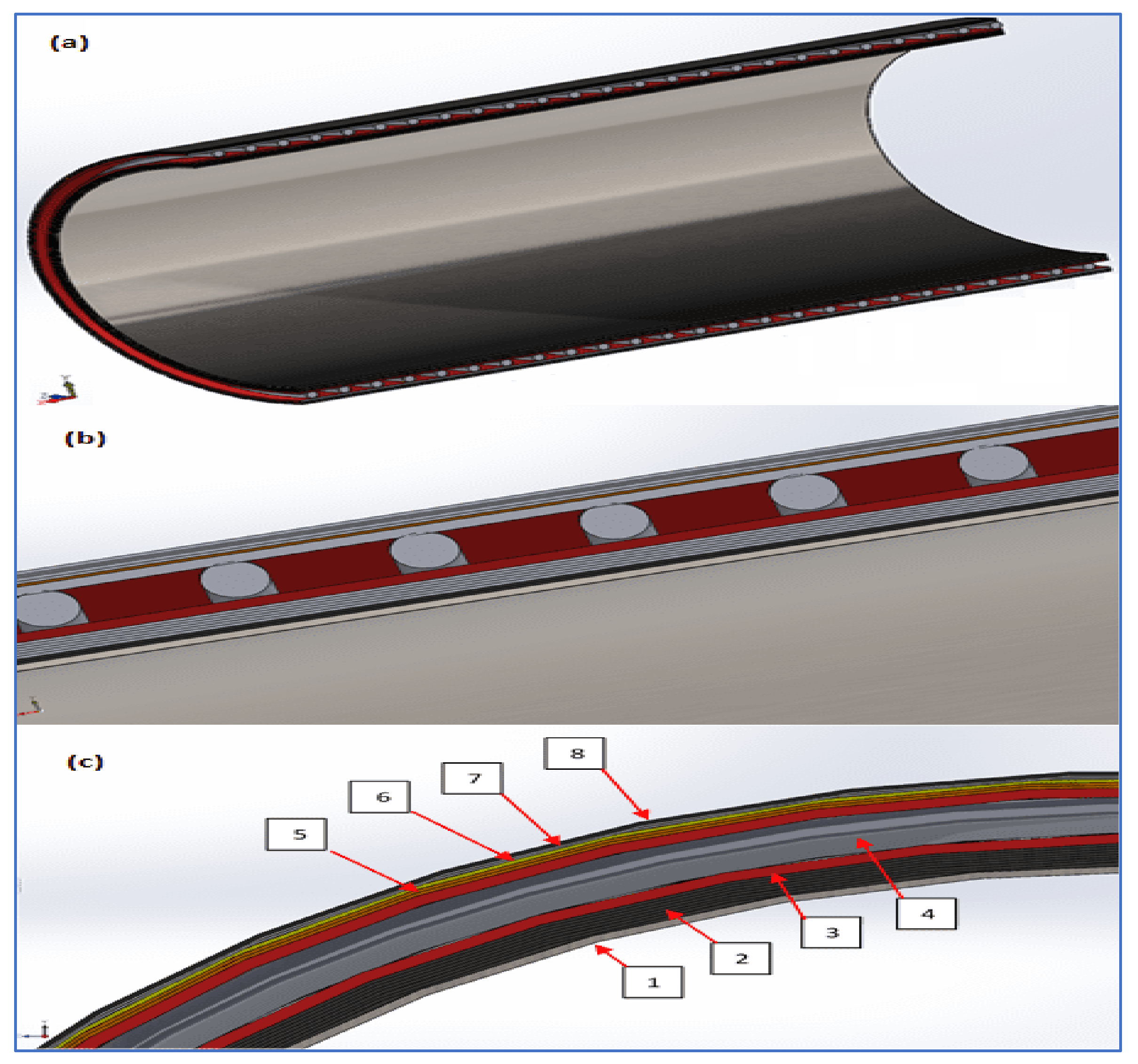
2.4. Marine Hose Layers
3. Finite Element Model
3.1. Local Design
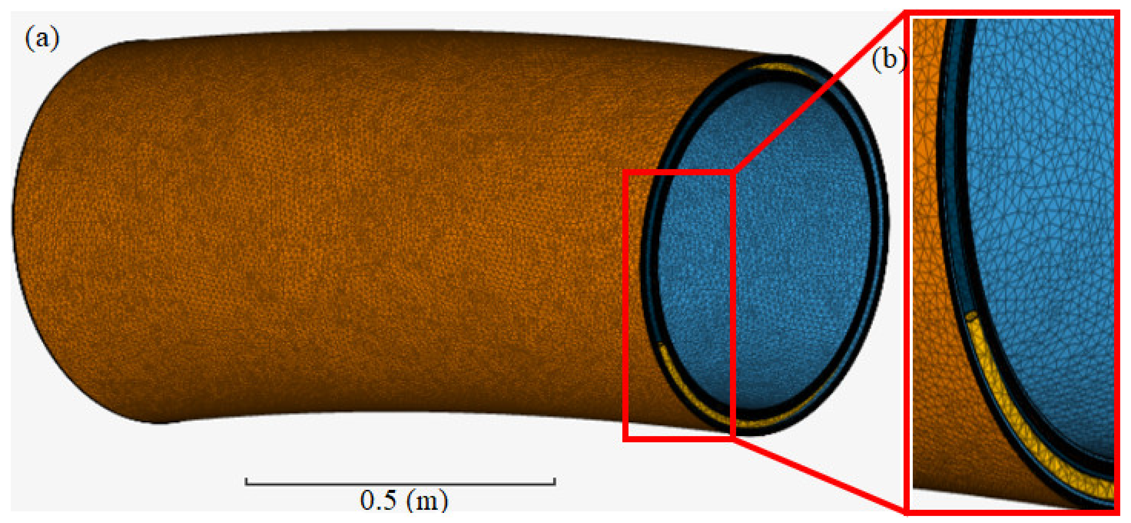
3.2. Mesh Details
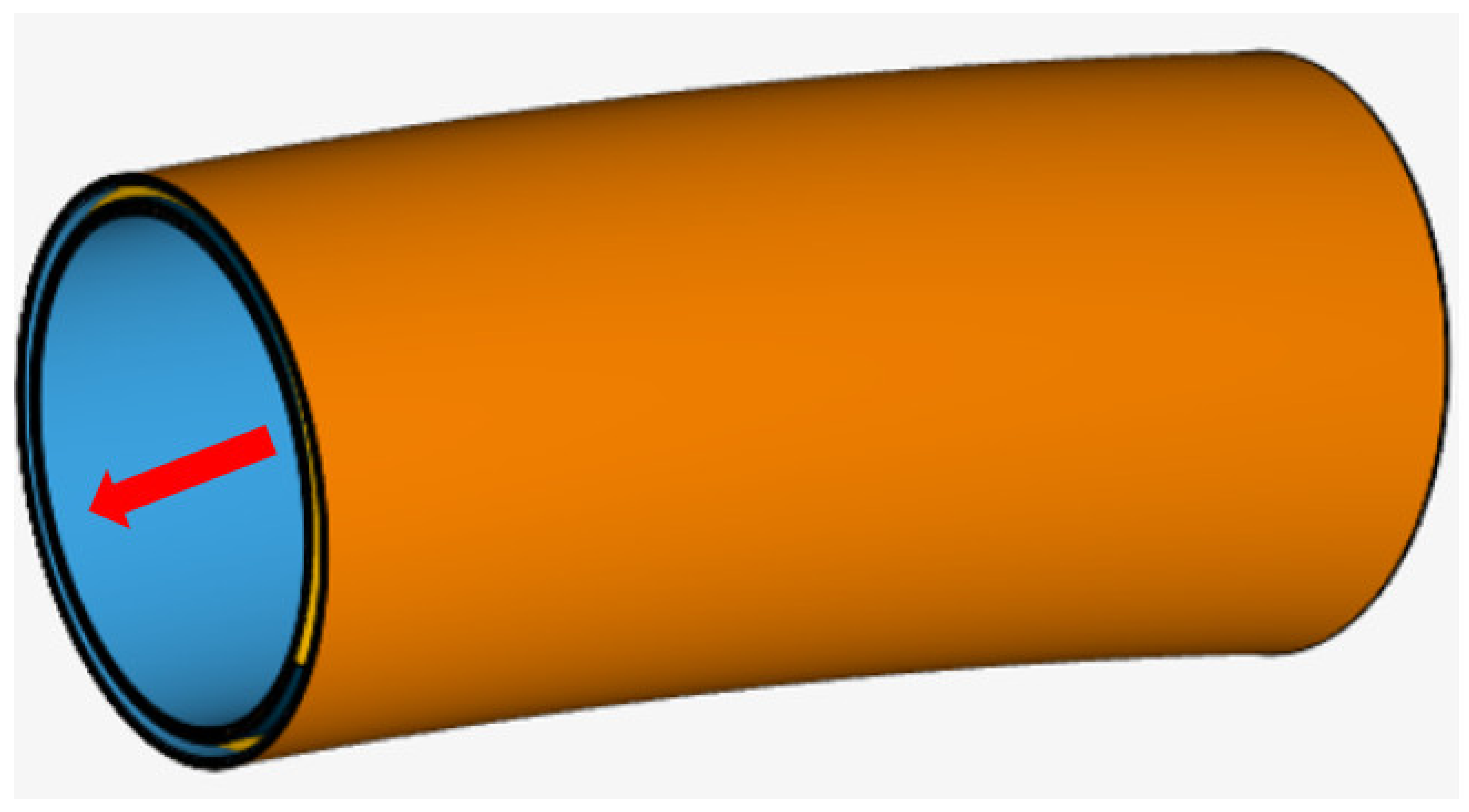
3.3. Boundary Conditions
3.4. Design Load Conditions
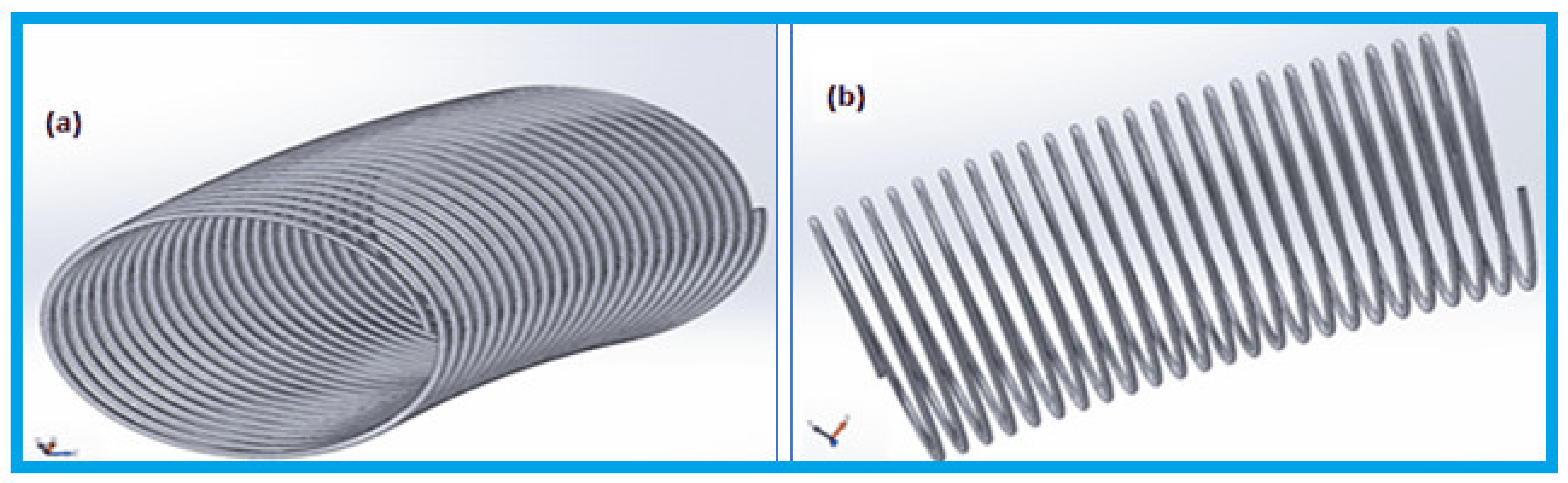
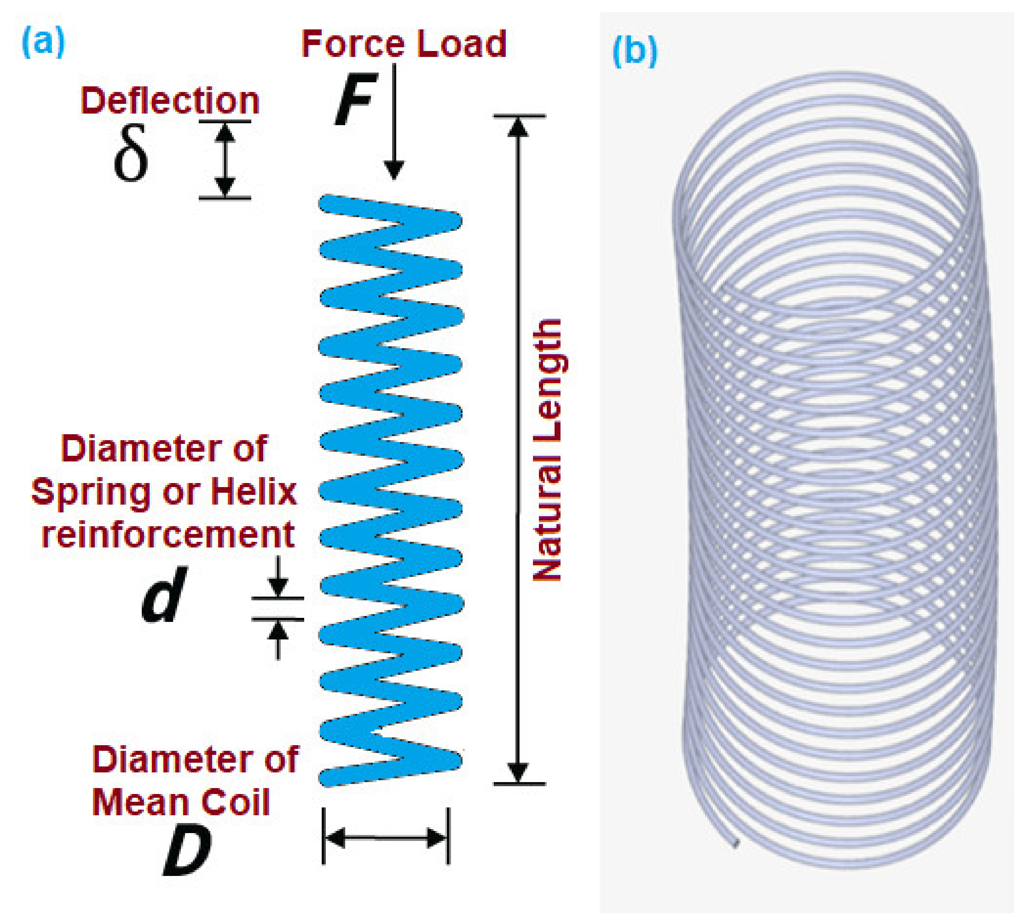
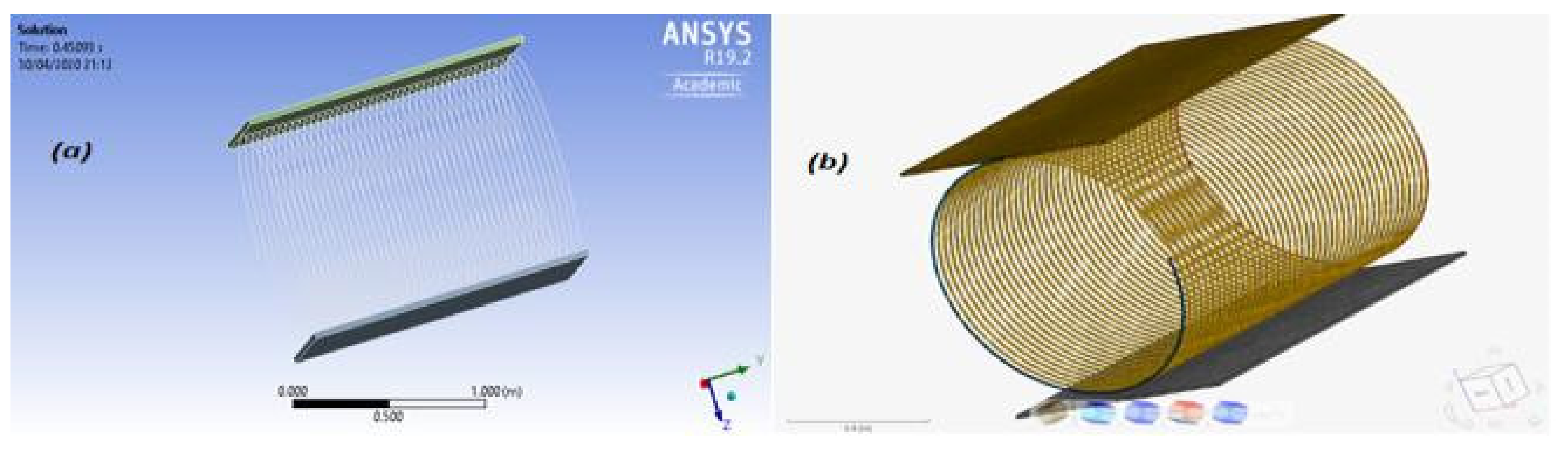
3.5. Helix Compression/Tension
3.6. Crush Load on Helix Spring
3.7. Validation
4. Results and Analysis
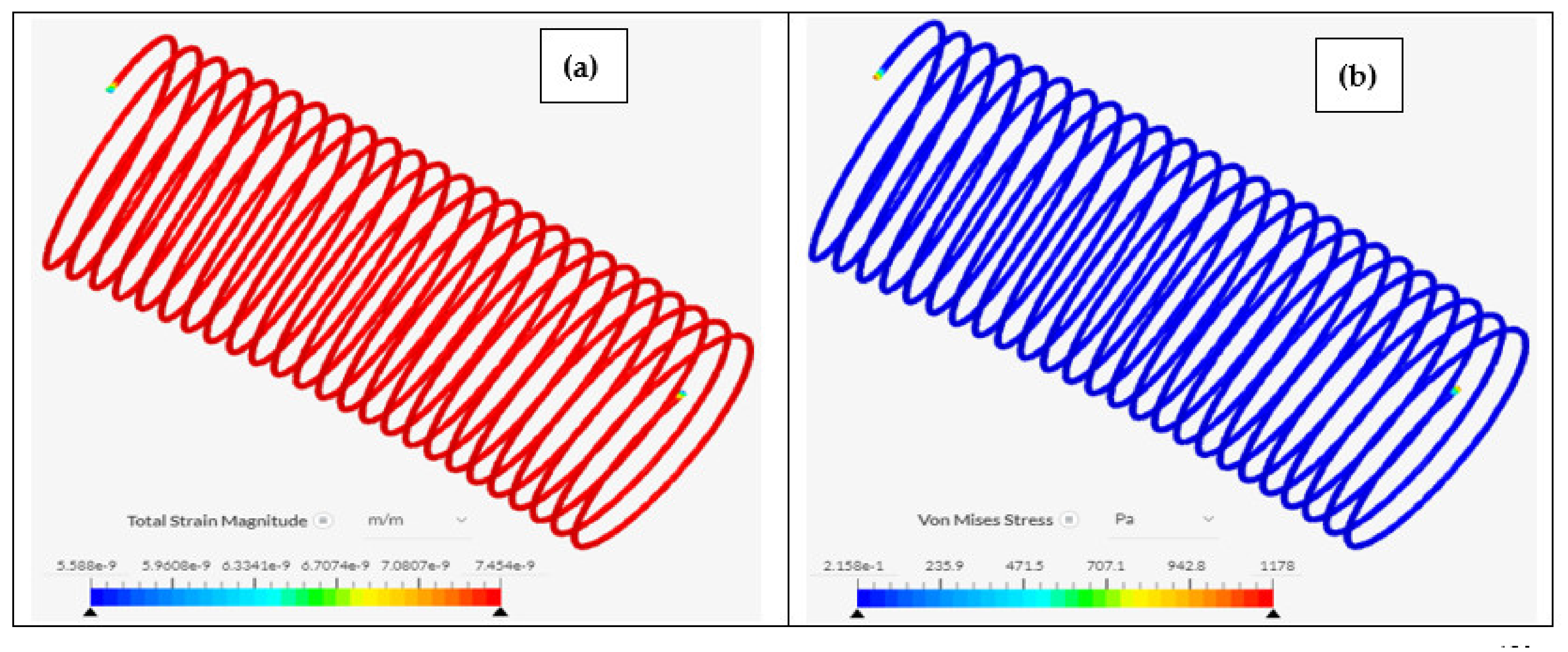
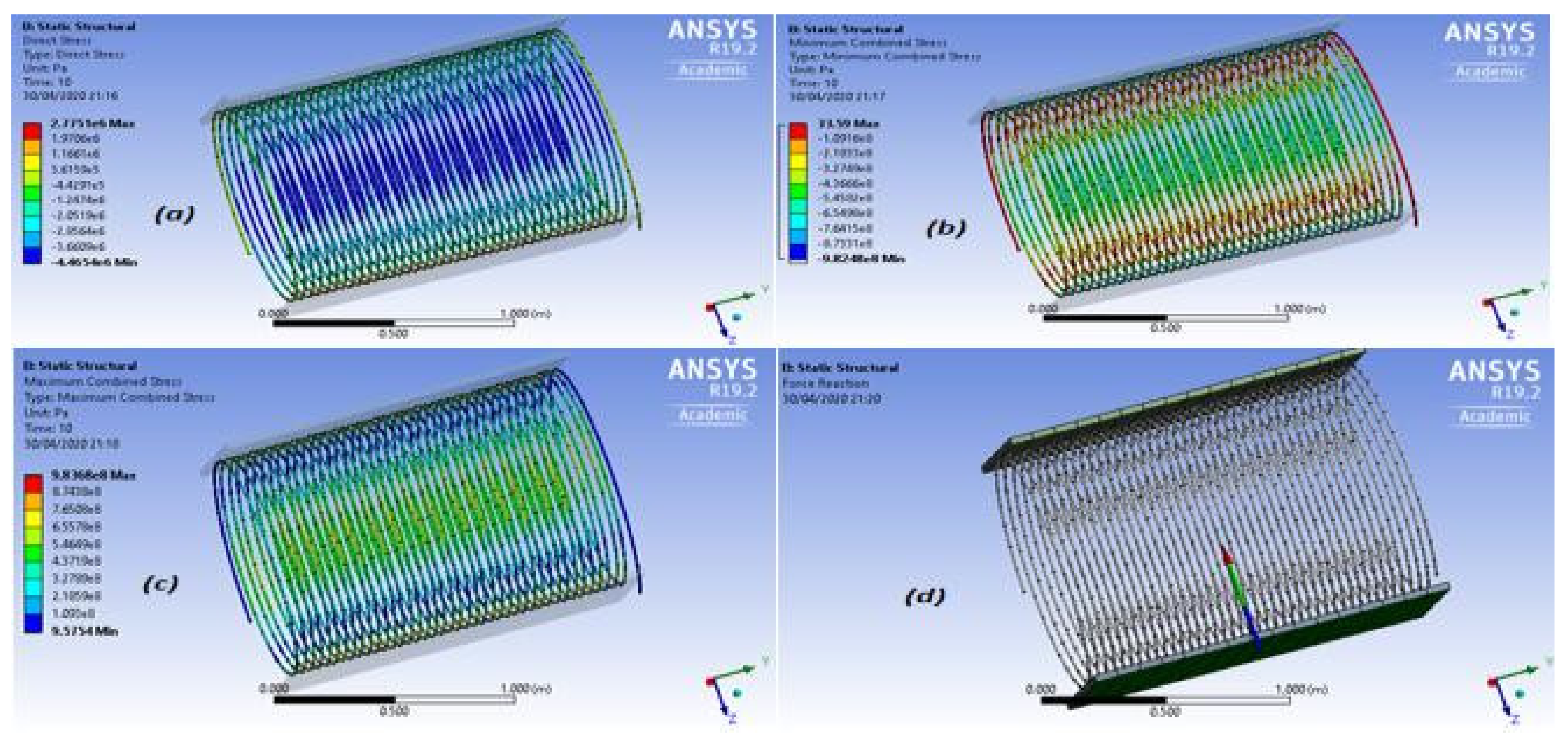
4.1. Results of Helix Reinforcement
4.2. Results of Crush Load on Helix Spring
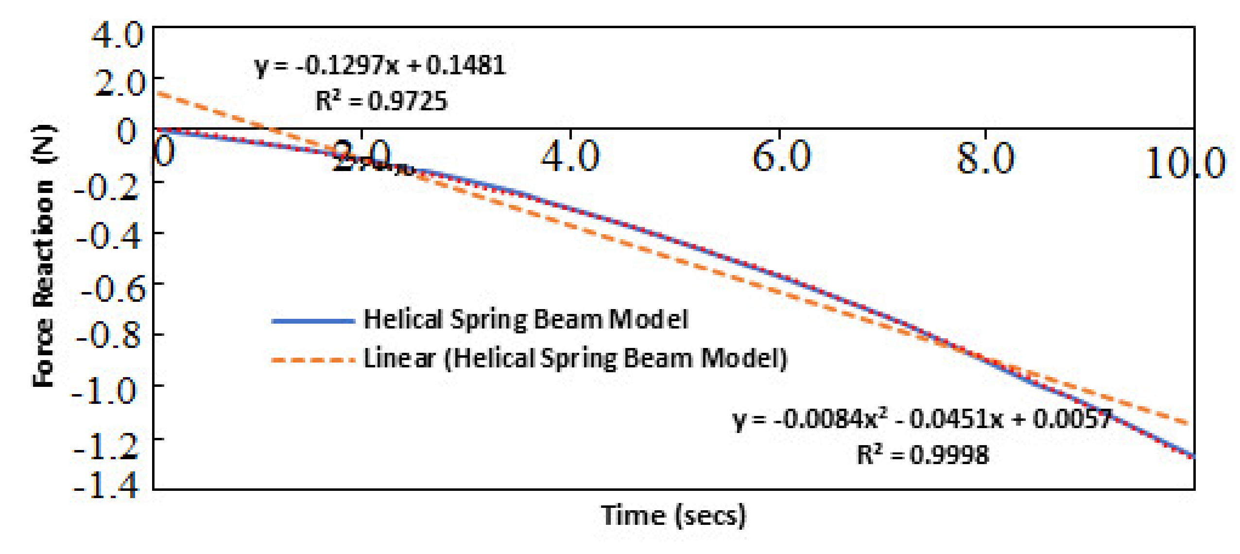
4.3. Results of Helix Spring Beam Model
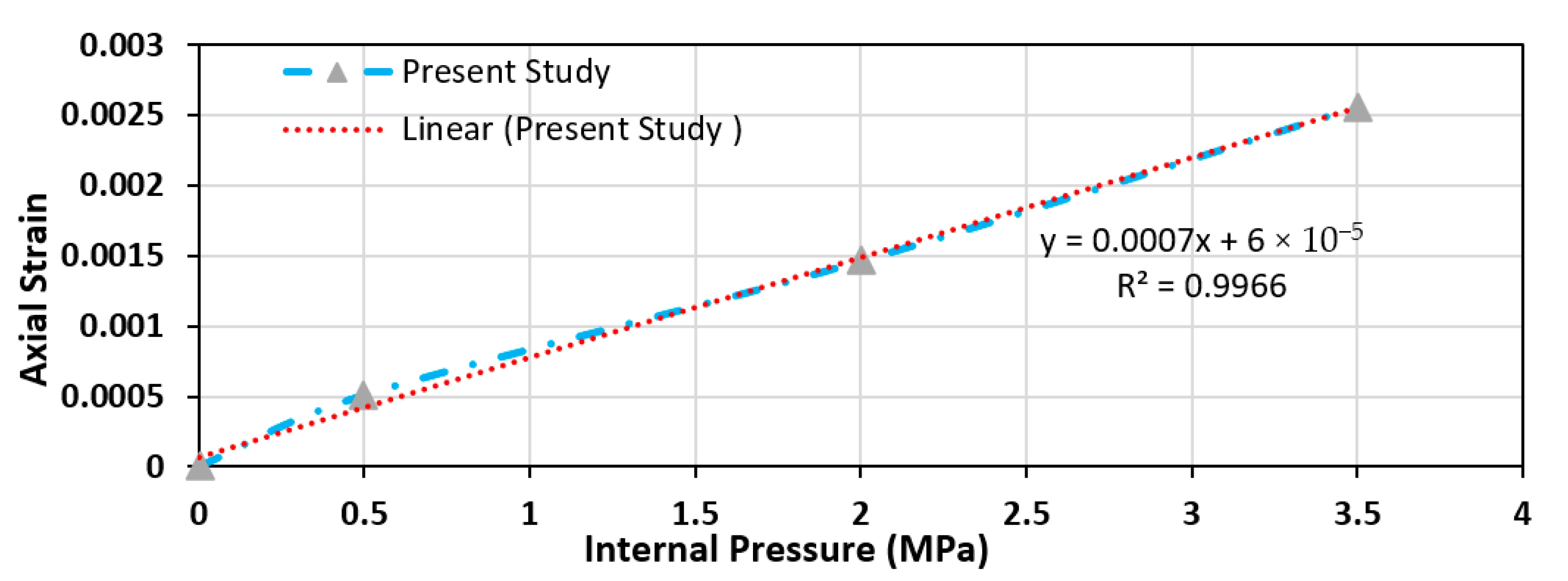
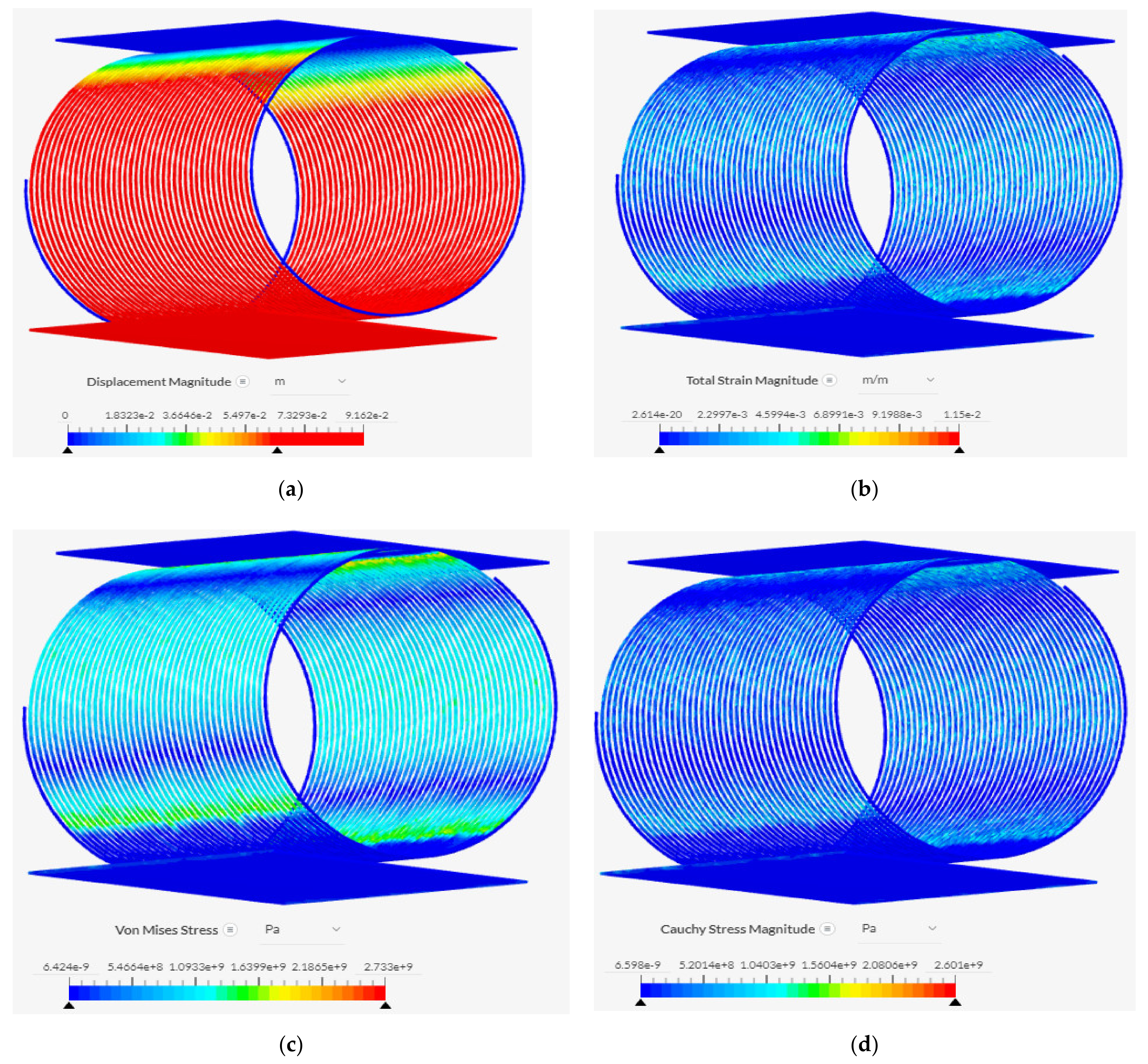
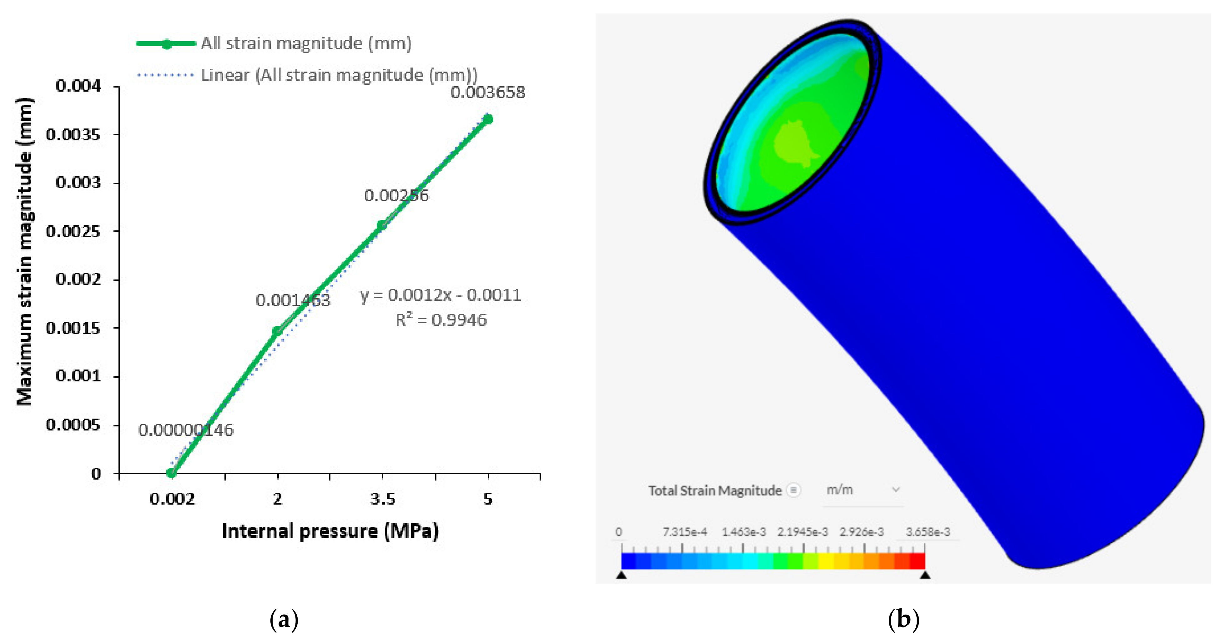
4.4. Results of Internal Pressure
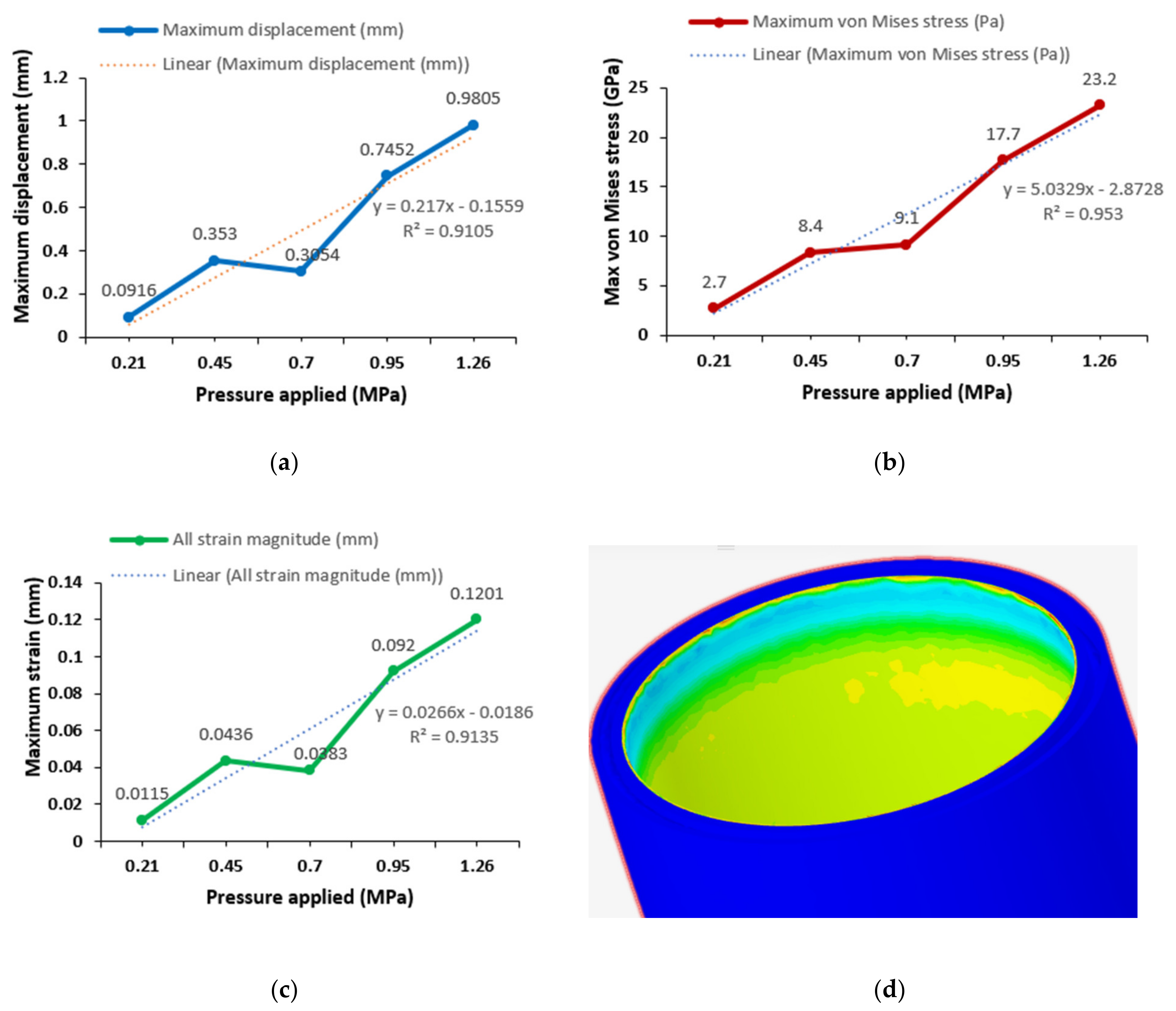
4.5. Results of External Pressure
4.6. Discussion of Results
5. Concluding Remarks
- The internal pressure and external pressure tests are very important aspects of the design of the marine bonded hoses. It was observed that the higher the pressure, the higher the von Mises stresses, maximum strains, and maximum deformations on the reeling hose, as presented in Section 4. However, detailed study is recommended based on combined loading and the effect of the composite materials in the layers.
- Based on the study of the reeling hose operation, some deformations were observed in the structure. However, this can be minimised by increasing the reinforcement of the marine hose, by using lighter materials with high strength–weight ratio, such as composites, or by applying the hose hydrodynamic loads. It is also recommended that the reeling be done under operational pressure and not design pressure, as the study shows that design pressure could be high. It is also recommended that an explicit code be used which runs better for simulating higher failure conditions in further studies.
- The crush load was a significant part of the study as it showed the behaviour of the helix spring reinforcement under compression. The spring material performed well as stainless steel, however further studies should consider other spring coil materials like composites. Secondly, further study is recommended on the detailed crush load based on different materials and hose layer delamination.
- Based on the result on the helix reinforcement, it is important to optimise the hose model and investigate further on the helix. The results of the study also showed that the strains along the hose sections are reflected from the helix reinforcement.
- In reality, based on oil field operation, the crush load analysis of the reeling hose section will consider HEV coupling along the reeling hose string. A detailed crush load effect is recommended to investigate the effect of couplings and end-fittings of marine hoses when in contact with the FPSO body or reeling drum. In addition, further research is also recommended on the reeling process under transient mode in the FEA, as well as the global design of the marine bonded hose under marine operations like reeling.
Author Contributions
Funding
Institutional Review Board Statement
Informed Consent Statement
Data Availability Statement
Acknowledgments
Conflicts of Interest
References
- Chesterton, C. A Global and Local Analysis of Offshore Composite Material Reeling Pipeline Hose, with FPSO Mounted Reel Drum. Ph.D. Thesis, Lancaster University, Lancaster, UK, 2020. [Google Scholar]
- Amaechi, C.V. Novel Design, Hydrodynamics and Mechanics of Marine Hoses in Oil/Gas Applications. Ph.D. Thesis, Lancaster University, Lancaster, UK, 2022. [Google Scholar]
- Odijie, A.C. Design of Paired Column Semisubmersible Hull. Ph.D. Thesis, Lancaster University, Lancaster, UK, 2016. Available online: https://eprints.lancs.ac.uk/id/eprint/86961/1/2016AgbomeriePhD.pdf (accessed on 14 June 2021).
- Odijie, A.C.; Wang, F.; Ye, J. A review of floating semisubmersible hull systems: Column stabilized unit. Ocean Eng. 2017, 144, 191–202. [Google Scholar] [CrossRef]
- Amaechi, C.V.; Wang, F.; Ye, J. Investigation on Hydrodynamic Characteristics, Wave–Current Interaction and Sensitivity Analysis of Submarine Hoses Attached to a CALM Buoy. J. Mar. Sci. Eng. 2022, 10, 120. [Google Scholar] [CrossRef]
- Amaechi, C.V.; Wang, F.; Ja’e, I.A.; Aboshio, A.; Odijie, A.C.; Ye, J. A literature review on the technologies of bonded hoses for marine applications. Ships Offshore Struct. 2022. [Google Scholar] [CrossRef]
- Ochoa, O.; Salama, M. Offshore composites: Transition barriers to an enabling technology. Compos. Sci. Technol. 2005, 65, 2588–2596. [Google Scholar] [CrossRef]
- Amaechi, C.V.; Ye, J. A numerical modeling approach to composite risers for deep waters. In Structural and Computational Mechanics Book Series, Proceedings of the ICCS20 20th International Conference on Composite Structures, Paris, France, 4–7 September 2017; Ferreira, A.J.M., Larbi, W., Deu, J.-F., Tornabene, F., Fantuzzi, N., Eds.; Societa Editrice Esculapio: Bologna, Italy, 2017; pp. 262–263. [Google Scholar]
- Amaechi, C.V.; Gillett, N.; Odijie, A.C.; Hou, X.; Ye, J. Composite risers for deep waters using a numerical modelling approach. Compos. Struct. 2019, 210, 486–499. [Google Scholar] [CrossRef]
- Amaechi, C.V.; Ye, J. Local tailored design of deep water composite risers subjected to burst, collapse and tension loads. Ocean Eng. 2021, in press. [Google Scholar] [CrossRef]
- Amaechi, C.V.; Gillett, N.; Odijie, A.C.; Wang, F.; Hou, X.; Ye, J. Local and global design of composite risers on truss SPAR platform in deep waters. In Proceedings of the 5th International Conference on Mechanics of Composites, Lisbon, Portugal, 1–4 July 2019; pp. 1–3. Available online: https://eprints.lancs.ac.uk/id/eprint/136431/4/Local_and_Global_analysis_of_Composite_Risers_MechComp2019_Conference_Victor.pdf (accessed on 23 November 2021).
- Chibueze, N.O.; Ossia, C.V.; Okoli, J.U. On the fatigue of steel catenary risers. Stroj. Vestn. J. Mech. Eng. 2016, 62, 751–756. [Google Scholar] [CrossRef]
- Ezeonwumelu, T.C.; Ossia, C.V.; Douglas, I.E. Fatigue damage of vertical rigid risers due to in-line vortex induced vibration in Nigeria shallow waters. Am. J. Mech. Eng. 2017, 5, 33–40. [Google Scholar] [CrossRef]
- Akpan, V.; Ossia, C.V.; Fayemi, F. On the study of wellhead fatigue due to vortex induced vibration in the Gulf of Guinea. J. Mech. Eng. Autom. 2017, 7, 8–15. [Google Scholar] [CrossRef]
- Udeze, K.U.; Ossia, C.V. Vortex induced vibration of subsea umbilicals: A case study of deep offshore Nigeria. Univers. J. Mech. Eng. 2017, 5, 35–46. [Google Scholar] [CrossRef][Green Version]
- Amaechi, C.V.; Wang, F.; Ye, J. Mathematical modelling of marine bonded hoses for single point mooring (SPM) systems, with catenary anchor leg mooring (CALM) buoy application—A review. J. Mar. Sci. Eng. 2021, 9, 1179. [Google Scholar] [CrossRef]
- Amaechi, C.V.; Chesterton, C.; Butler, H.O.; Wang, F.; Ye, J. Review on the design and mechanics of bonded marine hoses for catenary anchor leg mooring (CALM) buoys. Ocean Eng. 2021, 242, 110062. [Google Scholar] [CrossRef]
- Amaechi, C.V.; Chesterton, C.; Butler, H.O.; Wang, F.; Ye, J. An overview on bonded marine hoses for sustainable fluid transfer and (un)loading operations via floating offshore structures (FOS). J. Mar. Sci. Eng. 2021, 9, 1236. [Google Scholar] [CrossRef]
- Amaechi, C.V.; Ye, J.; Hou, X.; Wang, F.-C. Sensitivity Studies on offshore submarine hoses on CALM buoy with comparisons for Chinese-lantern and lazy-S configuration. In Proceedings of the 38th International Conference on Ocean, Offshore and Arctic Engineering, Glasgow, UK, 9–14 June 2019. [Google Scholar]
- Pham, D.-C.; Sridhar, N.; Qian, X.; Sobey, A.; Achintha, M.; Shenoi, A. A review on design, manufacture and mechanics of composite risers. Ocean Eng. 2016, 112, 82–96. [Google Scholar] [CrossRef]
- Toh, W.; Bin Tan, L.; Jaiman, R.K.; Tay, T.E.; Tan, V.B.C. A comprehensive study on composite risers: Material solution, local end fitting design and local design. Mar. Struct. 2018, 61, 155–169. [Google Scholar] [CrossRef]
- Lassen, T.; Eide, A.L.; Meling, T.S. Ultimate strength and fatigue durability of steel reinforced rubber loading hoses. In Proceedings of the ASME 2010 29th International Conference on Ocean, Offshore and Arctic Engineering, Shanghai, China, 6–11 June 2010; Volume 5, pp. 277–286. [Google Scholar] [CrossRef]
- Tonatto, M.L.; Tita, V.; Forte, M.M.; Amico, S.C. Multi-scale analyses of a floating marine hose with hybrid polyaramid/polyamide reinforcement cords. Mar. Struct. 2018, 60, 279–292. [Google Scholar] [CrossRef]
- Tonatto, M.L.; Roese, P.B.; Tita, V.; Forte, M.M.; Amico, S.C. Chapter 14: Offloading marine hoses: Computational and experimental analyses. In Marine Composites; Pemberton, R., Summerscales, J., Graham-Jones, J., Eds.; Woodhead Publishing Series in Composites Science and Engineering; Woodhead Publishing: Sawston, UK, 2019; pp. 89–416. [Google Scholar] [CrossRef]
- Donnell, L.H. Stability of Thin-Walled Tubes Under Torsion; Technical Report for NASA; NASA: Washington, DC, USA, 1933; p. 479. Available online: https://ntrs.nasa.gov/citations/19930091553 (accessed on 23 November 2021).
- Guz, I.A.; Menshykova, M.; Paik, J.K. Thick-walled composite tubes for offshore applications: An example of stress and failure analysis for filament-wound multi-layered pipes. Ships Offshore Struct. 2017, 12, 304–322. [Google Scholar] [CrossRef]
- Zheng, J.; Liu, P. Elasto-plastic stress analysis and burst strength evaluation of Al-carbon fiber/epoxy composite cylindrical laminates. Comput. Mater. Sci. 2008, 42, 453–461. [Google Scholar] [CrossRef]
- Amaechi, C.V.; Wang, F.; Hou, X.; Ye, J. Strength of submarine hoses in Chinese-lantern configuration from hydrodynamic loads on CALM buoy. Ocean Eng. 2018, 171, 429–442. [Google Scholar] [CrossRef]
- Amaechi, C.V.; Wang, F.; Ye, J. Numerical Assessment on the Dynamic Behaviour of Submarine Hoses Attached to CALM Buoy Configured as Lazy-S under Water Waves. J. Mar. Sci. Eng. 2021, 9, 1130. [Google Scholar] [CrossRef]
- Amaechi, C.V.; Wang, F.; Ye, J. Understanding the fluid-structure interaction from wave diffraction forces on CALM buoys: Numerical and analytical solutions. Ships Offshore Struct. 2021, in press. [Google Scholar] [CrossRef]
- Amaechi, C.V.; Wang, F.; Ye, J. Numerical studies on CALM buoy motion responses and the effect of buoy geometry cum skirt dimensions with its hydrodynamic waves-current interactions. Ocean Eng. 2022, 244, 110378. [Google Scholar] [CrossRef]
- Yokohama. Seaflex Yokohama Offshore Loading & Discharge Hose; The Yokohama Rubber Co. Ltd.: Hiratsuka City, Japan, 2016; Available online: https://www.y-yokohama.com/global/product/mb/pdf/resource/seaflex.pdf (accessed on 17 May 2021).
- Trelleborg. Oil & Gas Solutions: Oil & Gas Hoses for Enhanced Fluid Transfer Solutions; Trelleborg: Clemont-Ferrand, France, 2018; Volume 1, pp. 1–30. [Google Scholar]
- Continental. Continental Marine Hose Brochure; Dunlop Oil & Marine: Grimsby, UK, 2020; Available online: https://aosoffshore.com/wp-content/uploads/2020/02/ContiTech_Marine-Brochure.pdf (accessed on 17 February 2021).
- EMSTEC. EMSTEC Loading & Discharge Hoses for Offshore Moorings; EMSTEC: Rosengarten, Germany, 2016; Available online: https://denialink.eu/pdf/emstec.pdf (accessed on 29 September 2021).
- OIL. Offloading Hoses; Offspring International Limited: Dudley, UK, 2020; Available online: https://www.offspringinternational.com/wp-content/uploads/2020/06/OIL-Offloading-Hoses-Brochure-2020-W.pdf (accessed on 19 August 2021).
- Wang, C.; Shankar, K.; Morozov, E.V. Tailored design of top-tensioned composite risers for deep-water applications using three different approaches. Adv. Mech. Eng. 2017, 9, 1–18. [Google Scholar] [CrossRef]
- Wang, C.; Ge, S.; Sun, M.; Jia, Z.; Han, B. Comparative study of vortex-induced vibration of FRP composite risers with large length to diameter ratio under different environmental situations. Appl. Sci. 2019, 9, 517. [Google Scholar] [CrossRef]
- Wang, C.; Sun, M.; Shankar, K.; Xing, S.; Zhang, L. CFD simulation of vortex induced vibration for FRP composite riser with different modeling methods. Appl. Sci. 2018, 8, 684. [Google Scholar] [CrossRef]
- Van Onna, M.; Lyon, J. Installation of World’s 1st Subsesa Thermoplastic Composite Pipe Jumper on Alder. Available online: https://www.subseauk.com/documents/presentations/martin%20van%20onna%20-%20fields%20of%20the%20future%20-%20airborne.pdf (accessed on 23 November 2021).
- Van Onna, M.; Gioccobi, S.; de Boer, H. Evaluation of the first deployment of a composite downline in deepwater Brazil. In Proceedings of the Rio Oil & Gas Expo and Conference, Rio De Janeiro, Brazil, 15–18 September 2014; pp. 1–9. [Google Scholar]
- Roberts, D.; Hatton, S.A. Development and qualification of end fittings for composite riser pipe. In Proceedings of the Offshore Technology Conference, Houston, TX, USA, 6–9 May 2013. [Google Scholar] [CrossRef]
- Van Onna, M.; O’Brien, P. A new thermoplastic composite riser for deepwater application. In Subsea UK Conference; Subsea UK News: Aberdeen, UK, 2011; pp. 1–23. Available online: https://www.subseauk.com/documents/martinvanonnasubsea2011presentation.pdf (accessed on 23 November 2021).
- Smits, A.; Neto, T.B.; de Boer, H. Thermoplastic composite riser development for ultradeep water. In Proceedings of the Offshore Technology Conference, Houston, TX, USA, 30 April–3 May 2018; pp. 1–9. [Google Scholar] [CrossRef]
- MagmaGlobal. Ocyan–Magma CompRisers. Available online: https://www.magmaglobal.com/risers/ocyan-compriser/ (accessed on 23 May 2021).
- Yang, C.; Kang, Z. Assessment of Fatigue Damage Initiation in FPSO’s Oil Offloading Line in West Africa. In Proceedings of the 28th International Ocean and Polar Engineering Conference, Sapporo, Japan, 10–15 June 2018; Available online: https://onepetro.org/ISOPEIOPEC/proceedings-abstract/ISOPE18/All-ISOPE18/ISOPE-I-18-109/20158 (accessed on 23 November 2021).
- Amaechi, C.V.; Adefuye, E.F.; Oyetunji, A.K.; Ja’E, I.A.; Adelusi, I.; Odijie, A.C.; Wang, F. Numerical study on plastic strain distributions and mechanical behaviour of a tube under bending. Inventions 2022, 7, 9. [Google Scholar] [CrossRef]
- Tonatto, M.L.; Tita, V.; Araujo, R.T.; Forte, M.M.; Amico, S.C. Parametric analysis of an offloading hose under internal pressure via computational modelling. Mar. Struct. 2017, 51, 174–187. [Google Scholar] [CrossRef]
- Gao, P.; Gao, Q.; An, C.; Zeng, J. Analytical modeling for offshore composite rubber hose with spiral stiffeners under internal pressure. J. Reinf. Plast. Compos. 2020, 40, 352–364. [Google Scholar] [CrossRef]
- Tonatto, M.L.; Forte, M.M.; Tita, V.; Amico, S.C. Progressive damage modeling of spiral and ring composite structures for offloading hoses. Mater. Des. 2016, 108, 374–382. [Google Scholar] [CrossRef]
- Tonatto, M.L.; Forte, M.M.C.; Amico, S.C. Compressive-tensile fatigue behavior of cords/rubber composites. Polym. Test. 2017, 61, 185–190. [Google Scholar] [CrossRef]
- Yu, K.; Morozova, E.V.; Ashrafa, M.A.; Shankar, K. A review of the design and analysis of reinforced thermoplastic pipes for offshore applications. J. Reinf. Plast. Compos. 2017, 36, 1514–1530. [Google Scholar] [CrossRef]
- Yu, K.; Morozova, E.V.; Ashrafa, M.A.; Shankar, K. Numerical analysis of the mechanical behaviour of reinforced thermoplastic pipes under combined external pressure and bending. Compos. Struct. 2015, 131, 453–461. [Google Scholar] [CrossRef]
- Gu, F.; Huang, C.-K.; Zhou, J.; Li, L.-P. Mechanical response of steel wire wound reinforced rubber flexible pipe under internal pressure. J. Shanghai Jiaot. Univ. Sci. 2009, 14, 747–756. [Google Scholar] [CrossRef]
- Xu, Y.; Fang, P.; Bai, Y. Mechanical behavior of metallic strip flexible pipes during reeling operation. Mar. Struct. 2021, 77, 102942. [Google Scholar] [CrossRef]
- Hirdaris, S.; Bai, W.; Dessi, D.; Ergin, A.; Gu, X.; Hermundstad, O.; Huijsmans, R.; Iijima, K.; Nielsen, U.; Parunov, J.; et al. Loads for use in the design of ships and offshore structures. Ocean. Eng. 2014, 78, 131–174. [Google Scholar] [CrossRef]
- O’Donoghue, T. The Dynamic Behaviour of a Surface Hose Attached to a CALM Buoy. Ph.D. Thesis, Heriot-Watt University, Edinburgh, UK, 1987. Available online: https://www.ros.hw.ac.uk/handle/10399/1045?show=full (accessed on 17 May 2021).
- O’Donoghue, T.; Halliwell, A.R. Vertical bending moments and axial forces in a floating marine hose-string. Eng. Struct. 1990, 12, 124–133. [Google Scholar] [CrossRef]
- O’Donoghue, T.; Halliwell, A.R. Floating hose-strings attached to a calm buoy. In Proceedings of the Offshore Technology Conference, Houston, TX, USA, 2–5 May 1988. [Google Scholar] [CrossRef]
- Focke, E.S. Reeling of Tight Fit Pipe. Ph.D. Thesis, Delft University of Technology, Delft, The Netherlands, 2007. Available online: http://resolver.tudelft.nl/uuid:21348ba3-bce9-4b01-98fd-f1a32fafaaa9 (accessed on 19 August 2021).
- Nooij, S. Feasibility of IGW Technology in Offloading Hoses. Master’s Thesis, Delft University of Technology, Delft, The Netherlands, 2006. Available online: http://resolver.tudelft.nl/uuid:4617e7a0-b5d8-4c86-94d5-8d2037b31769 (accessed on 19 August 2021).
- Bai, Y.; Xu, F.; Cheng, P.; Badaruddin, M.F.; Ashri, M. Burst Capacity of Reinforced Thermoplastic Pipe (RTP) Under Internal Pressure. In Proceedings of the ASME 2011 30th International Conference on Ocean, Offshore and Arctic Engineering, Rotterdam, The Netherlands, 19–24 June 2011; Volume 4, pp. 281–288. [Google Scholar] [CrossRef]
- Bai, Y.; Liu, T.; Cheng, P.; Yuan, S.; Yao, D.; Tang, G. Buckling stability of steel strip reinforced thermoplastic pipe subjected to external pressure. Compos. Struct. 2016, 152, 528–537. [Google Scholar] [CrossRef]
- Zhou, Y.; Duan, M.; Ma, J.; Sun, G. Theoretical analysis of reinforcement layers in bonded flexible marine hose under internal pressure. Eng. Struct. 2018, 168, 384–398. [Google Scholar] [CrossRef]
- Zheng, J.-Y.; Gao, Y.-J.; Li, X.; Lin, X.-F.; Lu, Y.-B.; Zhu, Y.-C. Investigation on short-term burst pressure of plastic pipes reinforced by cross helically wound steel wires. J. Zhejiang Univ. Sci. A 2008, 9, 640–647. [Google Scholar] [CrossRef]
- Lipski, W. Mechanical Lined Pipe—Installation by Reel-Lay. p. 17. Available online: https://www.yumpu.com/en/document/read/26877695/mechanical-lined-pipe-installation-by-reel-lay-subsea-uk (accessed on 19 August 2021).
- Muren, J.; Caveny, K.; Eriksen, M.; Viko, N.G.; MÜLler-Allers, J.; JØRgen, K.U. Un-Bonded Flexible Risers–Recent Field Experience and Actions for Increased Robustness; 0389-26583-U-0032, Revision 5.0; PSA: Asker, Norway, 2013; Volume 2, pp. 1–78. Available online: https://www.ptil.no/contentassets/c2a5bd00e8214411ad5c4966009d6ade/un-bonded-flexible-risers--recent-field-experience-and-actions--for-increased-robustness.pdf (accessed on 17 June 2021).
- Løtveit, S.A.; Muren, J.; Nilsen-Aas, C. Bonded Flexibles–State of the Art Bonded Flexible Pipes; 26583U-1161480945-354, Revision 2.0, Approved on 17.12.2018; PSA: Asker, Norway, 2018; pp. 1–75. Available online: https://www.4subsea.com/wp-content/uploads/2019/01/PSA-Norway-State-of-the-art-Bonded-Flexible-Pipes-2018_4Subsea.pdf (accessed on 17 June 2021).
- Edward, C.; Dev, A.K. Assessment of CALM buoys motion response and dominant OPB/IPB inducing parameters on fatigue failure of offshore mooring chains. In Practical Design of Ships and Other Floating Structures, Proceedings of PRADS 2009 Conference; Springer International Publishing: Berlin/Heidelberg, Germany, 2020; Volume 64, pp. 548–579. [Google Scholar] [CrossRef]
- Jean, P.; Goessens, K.; L’hostis, D. Failure of chains by bending on deepwater mooring systems. In Proceedings of the Offshore Technology Conference, Houston, TX, USA, 2–5 May 2005. [Google Scholar] [CrossRef]
- Shoup, G.J.; Mueller, R.A. Analysis of a calm buoy anchor chain system. In Proceedings of the Offshore Technology Conference, Houston, TX, USA, 7–9 May 1984. [Google Scholar] [CrossRef]
- Xia, M.; Takayanagi, H.; Kemmochi, K. Analysis of multi-layered filament-wound composite pipes under internal pressure. Compos. Struct. 2001, 53, 483–491. [Google Scholar] [CrossRef]
- Sun, C.T.; Li, S. Three-dimensional effective elastic constant for thick laminates. J. Compos. Mater. 1988, 22, 629–639. [Google Scholar] [CrossRef]
- Ye, J.; Soldatos, K.P. Three-dimensional buckling analysis of laminated composite hollow cylinders and cylindrical panels. Int. J. Solid Struct. 1995, 32, 1949–1962. [Google Scholar] [CrossRef]
- Bakaiyan, H.; Hosseini, H.; Ameri, E. Analysis of multi-layered filament-wound composite pipes under combined internal pressure and thermomechanical loading with thermal variations. Compos. Struct. 2009, 88, 532–541. [Google Scholar] [CrossRef]
- Gao, Q.; Zhang, P.; Duan, M.; Yang, X.; Shi, W.; An, C.; Li, Z. Investigation on structural behavior of ring-stiffened composite offshore rubber hose under internal pressure. Appl. Ocean. Res. 2018, 79, 7–19. [Google Scholar] [CrossRef]
- Nassiraei, H.; Rezadoost, P. Static capacity of tubular X-joints reinforced with fiber reinforced polymer subjected to compressive load. Eng. Struct. 2021, 236, 112041. [Google Scholar] [CrossRef]
- Nassiraei, H.; Rezadoost, P. Local joint flexibility of tubular T/Y-joints retrofitted with GFRP under in-plane bending moment. Mar. Struct. 2021, 77, 102936. [Google Scholar] [CrossRef]
- Gonzalez, G.M.; Sousa, J.R.M.; Sagrilo, L.V.S. A study on the axial behavior of bonded flexible marine hoses. Mar. Syst. Ocean Technol. 2016, 11, 31–43. [Google Scholar] [CrossRef]
- Fergestad, D.; Løtveit, S.A. Handbook on Design and Operation of Flexible Pipes; SINTEF: Trondheim, Norway, 2014; Available online: https://core.ac.uk/download/pdf/52134083.pdf (accessed on 17 November 2021).
- Lassen, T.; Lem, A.I.; Imingen, G. Load response and finite element modelling of bonded loading hoses. In Proceedings of the ASME 2014 33rd International Conference on Ocean, Offshore and Arctic Engineering, San Francisco, CA, USA, 8–13 June 2014; Volume 6A. [Google Scholar] [CrossRef]
- Tonatto, M.L.; Tita, V.; Amico, S.C. Composite spirals and rings under flexural loading: Experimental and numerical analysis. J. Compos. Mater. 2020, 54, 2697–2705. [Google Scholar] [CrossRef]
- ANSYS. ANSYS Modeling and Meshing Guide. Release 9.0; ANSYS Inc.: Canonsburg, PA, USA, 2004; Available online: http://dl.mycivil.ir/reza/Ansys%20Modeling%20And%20Meshing%20Guide.pdf (accessed on 27 August 2021).
- ANSYS. ANSYS Meshing User’s Guide, Release 15.0; ANSYS Inc.: Canonsburg, PA, USA, 2013; Available online: https://www.academia.edu/27974461/ANSYS_Meshing_Users_Guide (accessed on 19 August 2021).
- Simscale Documentation. Available online: https://www.simscale.com/docs/ (accessed on 19 August 2021).
- Rabelo, A.S. Estudo Do Comportamento De Mangueiras Termoplásticas De Umbilicais Submarinos Submetidas A Carregamentos Mecânicos. Master’s Thesis, Universidade Federal do Rio de Janeiro (UFRJ) & COPPE, Rio de Janeiro, Brasil, 2013. Available online: https://w1files.solucaoatrio.net.br/atrio/ufrj-peno_upl//THESIS/6000252/2013_mestrando_alexandre_soares_rabelo_20200405214916875.pdf (accessed on 27 August 2021).
- Muren, J. PSA—Norway Flexible Pipe: Failure Modes, Inspection, Testing and Monitoring; PSA Norway: Asker, Norway, 2007; Available online: https://www.ptil.no/contentassets/a4c8365164094826a24499ef9f22742b/p5996rpt01rev02cseaflex_janmuren.pdf (accessed on 29 July 2021).
- Drumond, G.P.; Pasqualino, I.; Pinheiro, B.; Estefen, S. Pipelines, risers and umbilicals failures: A literature review. Ocean Eng. 2018, 148, 412–425. [Google Scholar] [CrossRef]
- Simonsen, A. Inspection and Monitoring Techniques for Un-Bonded Flexible Risers and Pipelines. Master’s Thesis, University of Stavanger, Stavanger, Norway, 2014. Available online: http://hdl.handle.net/11250/219671 (accessed on 27 August 2021).
- Hirdaris, S.E.; Lees, A.W. A conforming unified finite element formulation for the vibration of thick beams and frames. Int. J. Numer. Methods Eng. 2004, 62, 579–599. [Google Scholar] [CrossRef]
- Timoshenko, S.P. LXVI. On the correction of shear of the differential equation for transverse vibrations of prismatic bars. Lond. Edinb. Dublin Philos. Mag. J. Sci. 1921, 41, 744–746. [Google Scholar] [CrossRef]
- Timoshenko, S.P. X. On the transverse vibrations of bars of uniform cross-section. Lond. Edinb. Dublin Philos. Mag. J. Sci. 1921, 43, 125–131. [Google Scholar] [CrossRef]
- Timoshenko, S.; Woinowsky-krieger, S. Theory of Plates and Shells, 2nd ed.; McGraw-Hill: New York, NY, USA, 1959; pp. 1–566. [Google Scholar]
- API. API 17K. Specification for Bonded Flexible Pipe, 3rd ed.; American Petroleum Institute (API): Houston, TX, USA, 2017. [Google Scholar]
- ISO. ISO 13628-10. Petroleum and Natural Gas Industries–Design and Operation of Subsea Production Systems–Part 10: Specification for Bonded Flexible Pipe; International Organization for Standardization (ISO): Geneva, Switzerland, 2005. [Google Scholar]
- DNVGL. DNVGL-OS-E403. Offshore Loading Buoys; Det Norske Veritas & Germanischer Lloyd: Oslo, Norway, 2015; Available online: https://rules.dnv.com/docs/pdf/DNV/os/2015-07/DNVGL-OS-E403.pdf (accessed on 29 July 2021).
- ABS. Rules For Building And Classing–Single Point Moorings; American Bureau of Shipping (ABS): Houston, TX, USA, 2014; Available online: https://ww2.eagle.org/content/dam/eagle/rules-and-guides/current/offshore/8_rules-forbuildingandclassingsinglepointmoorings_2021/spm-rules-jan21.pdf (accessed on 29 July 2021).
- OCIMF. Single Point Mooring Maintenace and Operations Guide (SMOG); Witherby & Co. Ltd: London, UK, 1995. [Google Scholar]
- OCIMF. Guide to Manufacturing and Purchasing Hoses for Offshore Moorings (GMPHOM); Witherby Seamanship International Ltd.: Livingstone, UK, 2009. [Google Scholar]
- Wahl, A.M. Mechanical Springs, 1st ed.; Penton Publishing Company: Cleveland, OH, USA, 1944. [Google Scholar]


| Material | Density (kg/m3) | Young’s Modulus (Pa) | Bulk Modulus (Pa) | Shear Modulus (Pa) | Compressive Yield Strength (Pa) | Tensile Yield Strength (Pa) | Tensile Ultimate Strength (Pa) | Poisons Ratio, v |
|---|---|---|---|---|---|---|---|---|
| Structural Steel | 7850 | 2 × 10¹¹ | 1.6667 × 10¹¹ | 7.6923 × 10¹⁰ | 2.5 × 10⁸ | 2.5 × 10⁸ | 4.6 × 10⁸ | 0.3 |
| Nylon PA6/6 | 1140 | 1.06 × 10⁹ | 1.1778 × 10⁹ | 3.9259 × 10⁸ | 2.32 × 10⁹ | 4.31 × 10⁷ | 4.97 × 10⁷ | 0.35 |
| Nylon PA66-GF * | 1360 | 6.82 × 10⁹ | 7.5778 × 10⁹ | 2.5259 × 10⁹ | 3.45 × 10⁷ | 1.39 × 10⁸ | 1.49 × 10⁸ | 0.35 |
| CF (290GPa) +* | 1810 | 2.9 × 10¹¹ | 2.45 × 10¹¹ | 9 × 10⁹ | 5.7 × 10⁸ | 4.2 × 10⁹ | 6 × 10⁸ | 0.3 |
| Resin Polyester | 1200 | 3 × 10⁹ | 2.7174 × 10⁹ | 1.1398 × 10⁹ | 1.41 × 10⁸ | 1.28 × 10⁸ | 5.18 × 10⁷ | 0.316 |
| Layer | Liner | Main Plies | Filler | Helix | Holding Plies | Sub Cover | Breakers | Cover |
|---|---|---|---|---|---|---|---|---|
| Material | Structural Steel | Nylon 6/6 glass fibre reinforced (PA66-GF) | Nylon 6 (PA6) | Structural Steel | Resin polyester | Carbon fibre (290 GPa) | Resin polyester | Carbon fibre (290 GPa) |
| Layer | Inner Diameter (mm) | Outer Diameter (mm) | Thickness (mm) |
|---|---|---|---|
| Liner | 488.95 | 493.95 | 5 |
| Main ply 1 | 493.95 | 496 | 2.05 |
| Main ply 2 | 496 | 498.05 | 2.05 |
| Main ply 3 | 498.05 | 500.1 | 2.05 |
| Main plie 4 | 500.1 | 502.15 | 2.05 |
| Main ply 5 | 502.15 | 504.4 | 2.25 |
| Main ply 6 | 504.4 | 506.25 | 1.85 |
| Main ply 7 | 506.25 | 508.3 | 2.05 |
| Main ply 8 | 508.3 | 510.35 | 2.05 |
| Filler 1 | 510.35 | 517.35 | 7 |
| Steel helix | 517.35 | 545.79 | 14.22 ** |
| Filler 2 | 545.79 | 552.79 | 7 |
| Holding ply 1 | 552.79 | 554.84 | 2.05 |
| Holding ply 2 | 554.84 | 556.89 | 2.05 |
| Sub cover | 556.89 | 559.39 | 2.5 |
| Breaker 1 | 559.39 | 560.59 | 1.2 |
| Breaker 2 | 560.59 | 561.79 | 1.2 |
| Cover | 561.79 | 564.29 | 2.5 |
| Design Load | Loading Description |
|---|---|
| Burst (Internal Pressure) | Burst test at 2.0 MPa, 3.5 MPa and 5 MPa |
| Collapse (External Pressure) | Collapse test at 4.5 × 10⁵ Pa, 7 × 10⁵ Pa, 9.5 × 10⁵ Pa, 1.26 × 10⁶ Pa |
| Crushing Load | The crush load was an external pressure of 2.1 × 10⁵ Pa |
| Parameter | Value | Unit |
|---|---|---|
| Hose Nominal inner radius | 250 | m |
| Outer radius | 294 | mm |
| Length of Hose model | 1000 | mm |
| Mean Radius of helix reinforcement | 284 | mm |
| Diameter of helix reinforcement coil | 12.7 | mm |
| Pitch of helical reinforcement | 36 | mm |
| Total number of coil turns | 41 | - |
| Height of helix reinforcement | 1500 | mm |
| Width of helix reinforcement | 1200 | mm |
| Model Particulars | F.S of Composite Plies | F.S of Steel Layer |
|---|---|---|
| Present Study | 9.2 | 7 |
Publisher’s Note: MDPI stays neutral with regard to jurisdictional claims in published maps and institutional affiliations. |
© 2022 by the authors. Licensee MDPI, Basel, Switzerland. This article is an open access article distributed under the terms and conditions of the Creative Commons Attribution (CC BY) license (https://creativecommons.org/licenses/by/4.0/).
Share and Cite
Amaechi, C.V.; Chesterton, C.; Butler, H.O.; Gu, Z.; Odijie, A.C.; Wang, F.; Hou, X.; Ye, J. Finite Element Modelling on the Mechanical Behaviour of Marine Bonded Composite Hose (MBCH) under Burst and Collapse. J. Mar. Sci. Eng. 2022, 10, 151. https://doi.org/10.3390/jmse10020151
Amaechi CV, Chesterton C, Butler HO, Gu Z, Odijie AC, Wang F, Hou X, Ye J. Finite Element Modelling on the Mechanical Behaviour of Marine Bonded Composite Hose (MBCH) under Burst and Collapse. Journal of Marine Science and Engineering. 2022; 10(2):151. https://doi.org/10.3390/jmse10020151
Chicago/Turabian StyleAmaechi, Chiemela Victor, Cole Chesterton, Harrison Obed Butler, Zewen Gu, Agbomerie Charles Odijie, Facheng Wang, Xiaonan Hou, and Jianqiao Ye. 2022. "Finite Element Modelling on the Mechanical Behaviour of Marine Bonded Composite Hose (MBCH) under Burst and Collapse" Journal of Marine Science and Engineering 10, no. 2: 151. https://doi.org/10.3390/jmse10020151
APA StyleAmaechi, C. V., Chesterton, C., Butler, H. O., Gu, Z., Odijie, A. C., Wang, F., Hou, X., & Ye, J. (2022). Finite Element Modelling on the Mechanical Behaviour of Marine Bonded Composite Hose (MBCH) under Burst and Collapse. Journal of Marine Science and Engineering, 10(2), 151. https://doi.org/10.3390/jmse10020151