Article

Equivalent Aerodynamic Design of Blade for Offshore Floating Wind Turbine Model

School of Mechanical Engineering and Automation, Fuzhou University, Fuzhou 350108, China
*
Author to whom correspondence should be addressed.
J. Mar. Sci. Eng. 2022, 10(2), 132; https://doi.org/10.3390/jmse10020132
Submission received: 7 December 2021 / Revised: 8 January 2022 / Accepted: 12 January 2022 / Published: 20 January 2022
(This article belongs to the Topic Sustainable Energy Technology)

Abstract

:
The Froude-scaled offshore floating wind turbine model is inevitably affected by the Reynolds number effect, making the model unable to correctly reproduce the thrust performance of the reference wind turbine (RWT). To solve this problem, an Xfoil-AirfoilPrep-Matlab (XAM) system and a wide tip speed ratio search method (WTSM) are proposed to design a wide tip speed ratio (TSR) thrust-match model blade. The XAM system is utilized to select the best airfoil for WTSM by calculating the lift and drag coefficients of several airfoils. The WTSM is utilized to optimize the blade chord and twist. It formalizes the blade chord and twist by polynomials and then optimizes the polynomial coefficients. The thrust coefficients construct the optimization object at different TSRs. For validating the effect of the redesigned blade, the thrust performance is compared to that of the RWT blade. In addition, the thrust performance of redesigned blade at different pitch angles is also calculated and compared to those of the RWT blade. Results show that the thrust performance of redesigned blade matches well with that of the RWT blade at 0 pitch angle, and it can also match the variations of that of the RWT blade at the other pitch angles well.

1. Introduction

With the development of the offshore floating wind turbine (OFWT) technique, the capacity and geometry of OFWTs are rapidly increasing [1,2,3,4,5]. The increases promote the need for the OFWT design cost reduction approach [6]. In this scenario, the scaled model method is the most commonly used one [7,8]. It works by constructing a model to validate the static and dynamic characteristics of OFWT. However, due to the Reynolds number effect (RNE), the Froude-scaled OFWT model cannot correctly reproduce the aerodynamic performance of the reference wind turbine (RWT) [9,10,11,12], especially the thrust performance.
To solve this problem, the redesigning blade method is proposed and widely studied [13]. It reproduces the thrust performance of the RWT blade by designing a dedicated blade. The design includes two steps. The first step is choosing a thin airfoil to replace the original airfoils used in the RWT blade. The second step is adjusting the blade geometry, which is mainly described by the blade chord and twist, by manual or optimization algorithm to obtain a redesigned blade matching the RWT blade in thrust performance.
In the first step, most researchers have just selected an airfoil with an advantage performance over the original airfoils at a low Reynolds number [14,15,16,17,18]. Only a few studies are focusing on how to get an airfoil with better performance for redesigning the blade. For example, Timmer et al. [19] focused on the Delft University wind turbine dedicated airfoils. They revealed the influence of Gurney flaps, trailing edge wedges, vortex generators and tripwires on the airfoil performance. Zhang et al. [20] proposed a method to design the new airfoils using characteristics. A new airfoil based on E387 airfoil working at Re = 2.0 × 10⁵ (Reynolds number is 2.0 × 10⁵) and another new airfoil based on PSU 94-097 airfoil working at Re = 4.0 × 10⁵ were designed with enhanced aerodynamic properties. Obviously, these studies cannot fully guide the airfoil selection.
Compared to the first step, the second step of redesigning the blade has received more attention. Martin et al. [21] designed a dedicated blade based on AG 04 airfoil by manually adjusting the blade chord and twist. This design aimed to create a blade matching the thrust coefficient CT, which is usually used to assess the thrust performance, at the rated tip speed ratio (TSR, approximately 7) and maximized the peak value of the power coefficient, which is usually used to assess the power performance. After that, some verifications were carried out by simulation tools and model tests. Bayati et al. [22] designed a model blade based on SD7032 airfoil by analytical method. This blade was designed to match the CT–TSR curve with the RWT blade at a special TSR. Then, it was applied for some simulations and model tests. Chen et al. [23] proposed a high-order redesign method for model blade optimization, describing the blade chord and twist by a quaternary polynomial and a quadratic polynomial. The polynomial coefficients were taken as the variables and optimized for the CT at rated TSR. The redesigned blade can meet the CT of the RWT blade and make up for the discrepancy of the rotor thrust by the pitch angle adjustment at other TSRs. Wen et al. [24] proposed a Maximum Lift Tracking approach and Load Distribution Match approach to design a blade with the desired thrust at rated TSR. Both approaches had been verified by simulation tools. Du et al. [25] designed a model blade based on NACA 4412 airfoil by Pattern Search (PS) method. The design object guaranteed the CT of the blade at rated TSR and considered the weight of the model blade. It can be found that there has been a great deal of redesigned blades in the past decades. However, the optimization of the geometrical parameters of the redesigned blade is almost limited to the objective of several special TSRs. In actual operations, the TSR of OFWTs is time-varying under the unsteady inflow wind, wake and control strategy [26,27,28,29]. Thus, it is required that a kind of redesigned blade has the thrust performance matching that of RWT blade in a wide range of TSR.
To solve these problems, this study first proposes an Xfoil-AirfoilPrep-Matlab (XAM) system to reference alternative airfoil selection and a wide TSR search method (WTSM) to optimize the chord and twist of the redesigned blade. The XAM system is operated based on Matlab. It runs the Xfoil and the AirfoilPrep to calculate the aerodynamic parameters of airfoils. Then, the parameters of different airfoils will be compared to select the best alternative airfoil. The WTSM takes thrust coefficients at multi-TSR as the design objective to optimize the blade chord and twist. Then, the grasshopper optimization algorithm (GOA) is utilized to search for the best solution in this study. Thus, the thrust performance of the redesigned blade can match the RWT blade at a wide range of TSR. The result is more consistent with the actual working condition.
The following contents can be organized as follows. In Section 2, the scaling laws of the OFWT model and RNE are introduced. In Section 3, the XAM system is introduced in detail, and a comparison among 767 airfoils is discussed. In Section 4, the WTSM is constructed and carried out. In Section 5, some conclusions are summarized.

2. Scaling Laws and RNE

To design a wide TSR thrust matched blade, the reason for RNE and its effect mechanism should be deeply studied. Thus, the scaling laws of the Froude-scaled OFWT model are first introduced in this section. Then, the inevitability of RNE is analyzed based on the scaling laws, and the effect mechanism of RNE is constructed. Finally, based on the effect mechanism of RNE, a preliminary airfoil selection method is proposed to guidance redesigning the blade.

2.1. Scaling Laws

The OFWT model is commonly designed to satisfy the geometry, kinematics and dynamics similarity [30]. To reach these goals, the scaling factors of different properties should be fully considered. First of all, the geometric scaling factor should be defined as follows:
λ = L f L m
where λ is the geometric scaling factor (λ = 80 in this study), L is the characteristic length, the subscript f and m are the RWT (NREL 5MW wind turbine [31] in this study) and OFWT model, respectively.
Besides, as marine machinery, the OFWT model should be designed for hydrodynamics similarity. Thus, it should satisfy the Froude scaling law. The Froude scaling can be described as follows:
F r = U f g f L f = U m g m L m
where Fr is the Froude number, U is the velocity of fluid and g is the gravitational acceleration.
In addition, the kinematic characteristics of wind turbines are indicated by the TSR. The equation of TSR is shown as follows:
TSR = ω R U
where ω is the angular velocity of the rotor and R is the radius of the rotor.
Due to the gf = gm, the scaling factors of different properties can be obtained through the dimensional analysis based on the definitions of geometric scaling factors and the Froude scaling law. According to the related scaling factors, it can be found that the kinematics similarity of the OFWT model is also guaranteed well.

2.2. RNE

The Reynolds number is a dimensionless parameter used to characterize the fluid flow (i.e., wind), and it can be described as follows:
R e = L U ν
where Re is the Reynolds number (Re = 11.5 × 10⁶ for the RWT [21]), ν is the kinematic viscosity of fluid flow.
According to the related scaling factors obtained through the dimensional analysis, the mapping from the Reynolds number of RWT to the OFWT model can be concluded as follows:
R e m = λ 1.5 R e f
Equation (5) points out that the Reynolds number of the OFWT model is inevitable smaller than that of the RWT. This difference will lead to a significant decrease in the aerodynamic performance of the OFWT model, which is named RNE. To accurately study the influence of RNE on the performance of airfoils, the DU40 airfoil is taken as the example to compare the lift and drag coefficients (CL and CD) of airfoils at the reference and model Reynolds numbers. The results are shown in Figure 1, and α is the angle of attack. It shows that there are several significant changes in airfoil performance resulting from RNE. The CL significantly decreases, and the CD slightly increases. It means the peak CL/CD also decreases significantly. As the Blade Element Momentum (BEM) points that, the CT of blade sections is mainly influenced by the peak CL of airfoil, the valley CD and the peak CL/CD of airfoil [32,33]. Thus, to design a thrust match blade, airfoils with larger peak CL, smaller valley CD and larger CL/CD are needed first.

3. Airfoil Selection

3.1. XAM System

To find the required airfoils, the CL and CD of several airfoils should be calculated and compared with each other. Based on this goal, a XAM system, which integrates Xfoil [34], AirfoilPrep [35] and Matlab software, is proposed in this study. This system can fulfill the calculation of the CL and CD of several airfoils at the full 360-degree angle of attack, the extraction of the critical data and the comparison of the aerodynamic performance of airfoils.
The flowchart of the XAM system is shown in Figure 2. Firstly, the studied airfoil number, airfoil geometries and Re are read. Secondly, a bat file is written based on airfoil geometries and used to drive the Xfoil. Thirdly, the CL and CD at a small range of α are processed to the full 360-degree CL and CD data by AirfoilPrep. Fourthly, the preliminary screening conditions are determined according to the maximum peak CL, the minimum valley CD and the maximum peak CL/CD of airfoils. Then, several airfoils are selected based on the preliminary screening conditions. Afterward, the scores of the selected airfoils are calculated by a dedicated score method. Finally, the CL and CD of the airfoil with the highest score are output.

3.2. Result and Discussion of Airfoil Performance

In this study, the preliminary screening conditions of the XAM system are chosen through some tests. The mentioned preliminary screening conditions are set as follows: (1) the peak CL should be greater than 75% of the maximum, (2) the valley CD should be less than the 125% of minimum, (3) the peak CL/CD should be greater than the 75% of the maximum.
In addition, the dedicated score method is defined as follows. Firstly, the peak CL, the valley CD and the peak CL/CD were normalized and scored. Secondly, in this study, the weights of the peak CL, the valley CD and the peak CL/CD is set as 1/3 for the complicated relationship between the mentioned parameters and the aerodynamic performance of airfoils. The optimal study of the weights will be carried out in our future researches. Finally, the score of an airfoil is formularized as follows:
Q = Q L + Q D + Q L / D 3
Q L = C Lp C Lp , min C Lp , max C Lp , min
Q D = 1 C Dv C Dv , min C Dv , max C Dv , min
Q L / D = ( C L / C D ) p ( C L / C D ) min ( C L / C D ) max ( C L / C D ) min
where Q is the final score of an airfoil, QL is the score of an airfoil in the peak CL, QD is the score of an airfoil in the valley CD, QL/D is the score of an airfoil in the peak CL/CD, CLp is the peak CL of the airfoil, CLp,min and CLp,max are the boundary values of peak CL of the selected airfoils, CDv is the valley CD of the airfoil, CDv,min and CDv,max are the boundary values of valley CD of the selected airfoils, (CL/CD)p is the peak CL/CD of the airfoil, (CL/CD)p,min and (CL/CD)p,max are the boundary values of peak CL/CD of the selected airfoils.
Seven hundred and sixty-seven airfoils with a thickness between 1% and 8% are served for our study. Moreover, 28 airfoils are selected out by the preliminary screening conditions. These airfoils have a peak CL greater than 1.0286, a valley CD less than 0.0298 and a peak CL/CD greater than 10.1181, simultaneously. Then, the scores of these airfoils are calculated based on the dedicated score method. The peak CL, the valley CD, the peak CL/CD and the final scores of 28 selected airfoils are shown in Table 1.
As shown in Table 1, the AG 14 airfoil has the highest score, 0.7286. Thus, it is the best choice among the 767 airfoils. The geometry and aerodynamic performance of AG 14 airfoil at the model Reynolds number are shown in Figure 3 and Figure 4, respectively. It is worth noting that a different result may be obtained using other criteria, and it will be studied in our future research.

4. Redesigning Blade Solution

4.1. WTSM

The rated thrust coefficient is usually taken as the optimization object of redesigning the blade in the previous studies. However, it cannot promise the thrust performance of the OFWT model matching the RWT blade under other working conditions. This will lead to deviations in research related to unsteady inflow wind, wake and control strategy. To solve this problem, a WTSM is proposed to design a wide TSR thrust-match blade in this study. The WTSM reaches this goal by taking the thrust coefficients at multi-TSR as the optimization object in the design process. The flowchart of WTSM is shown in Figure 5. First is fitting the blade chord and twist of the RWT blade to a quaternary polynomial and a quadratic polynomial, respectively. Second is clarifying the constraints of blade chord and twist. Then, selecting an appropriate alternative airfoil through the XAM system (AG 14 airfoil in this study). Afterward, the blade chord and twist polynomial coefficients are taken as the design variables to search for the result with a minimum target value. Finally, the blade chord and twist are output.
In the WTSM, the constraints are mainly caused by the blade geometry. Firstly, the chord and twist of every blade section should be positive. Secondly, the blade tip chord should not be a large value, and the blade root twist should not be a large value. These requirements on blade chord and twist can be described as follows:
c tip / R < ε 1 c r / R > 0 β root < ε 2 β r > 0
where c is the chord of blade section, β is the twist of blade section, the ε1 and ε2 are constants (refer to the RWT, ε1 = 0.04, ε2 = 14 in this study), the subscript tip, r and root are the tip of the blade, the position with distance r from the hub center and the root of the blade, respectively.
In terms of the optimization object, due to the WTSM taking the thrust coefficients at multi-TSR as the optimization object in the design process, it should be defined as follows:
F = min ( 1 n ( C Tr i δ C Tf i ) )
where n is the number of involved TSRs, δ is an 8-dimensional vector that represents all design variables (the coefficients of blade chord polynomial and blade twist polynomial), CTri is the thrust coefficient of the redesigned blade in i-th TSR point, CTfi is the thrust coefficient of the RWT blade in i-th TSR point
It is obvious that the number of considered TSRs is one of the critical factors affecting the result. In this study, 22 TSR points are taken into consideration, and the corresponding CT of the RWT blade can be obtained through OpenFAST.
Finally, the lower boundary (lb) and upper boundary (ub) of the search range are shown in Table 2. [lb, ub] is the limited range of δ and is determined by experience.

4.2. Some Modifications in GOA

GOA is chosen to complete the search process of WTSM for its superior global optimization capacity [36]. It randomly generates the initial positions (the initial value) in the given optimization range and then calculates their corresponding objective values. Then, the current position (the current value) Xi in the d-th dimension of the variable are updated for the next iteration by the following equation [37]:
X i d = C j = 1 j i N C u b d l b d 2 s x j d x i d x j x i d i j + T d
where N is the population, [lbd, ubd] is the limited range of the d-th variable, dij is the distance from individual xi to xj, and Td is the target position (the best position so far). C is a decreasing factor to balance the global search ability of GOA, and it can be defined as follows:
C = C max l C max C min T max
where Cmax and Cmin are the boundaries of the variation interval of C, l is the present iteration number, and Tmax is the iterative upper bound.
While s is a defined nonlinear action function used to adjust the social force, which is formulated as follows:
s ( d ) = f e d l e d
where f and d are two constants affecting the intensities of attraction and attractive length scale, respectively. Commonly, the value can be fixed as f = 1.5 and d = 0.5, respectively [36].
It is worth noting that there are some constraints in the redesigning blade process. Thus, some modifications have been done to the generation rules of the initial points. When a new initial value is generated, it should be verified to the constraints, if the constraints are satisfied, the initial value is recorded, otherwise, it should be regenerated.

4.3. Results and Discussion

In this study, the population of GOA is set as 4000, and the iteration is set as 10. The blade chord and twist results are compared with the RWT blade in Figure 6. It shows that the redesigned blade has an increase in chord and a decrease in twist. The increased blade chord can catch more wind power and slightly increase the Reynolds number. The decreased twist will lead the airfoil, which has poor performance due to the RNE, to operate at a better angle of attack. Similar findings can be found in other studies [21,24]. In addition, the smoothness of the chord and twist curve also prove the advantage of using the polynomial coefficients as the design variable.
The comparison of the thrust coefficient between the redesigned blade and the RWT blade is shown in Figure 7a. The relative error is shown in Figure 7b. To show the effectiveness of WTSM, a blade redesigned by Pattern Search (PS) in 1/50th with Du et al.’s study is also present in Figure 7a and denoted as PS [25].
As shown in Figure 7a, the CT-TSR curve of the PS blade, which optimizes the blade chord and twist in a single TSR by PS method, can only match the RWT blade at a special TSR. In contrast, the CT-TSR curve of the redesigned blade is matched well with the RWT blade from TSR = 3 to TSR = 11. Moreover, it can be found in Figure 7b that the relative errors of the redesigned blade to RWT blade are almost less than 5%, except for the two points TSR = 3 (8%) and TSR = 5 (6%). This proves the redesigned blade based on WTSM can reproduce the thrust performance of RWT at a wide range of TSR.

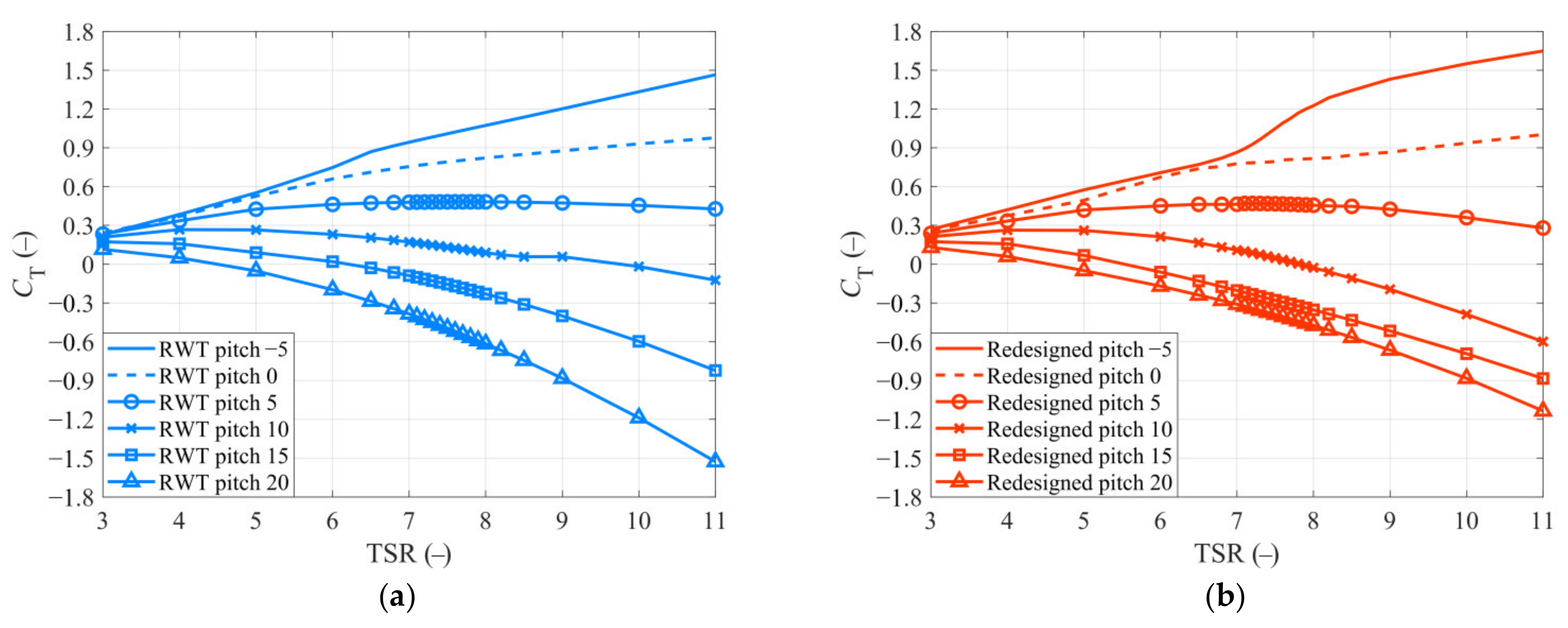
4.4. Aerodynamic Analysis with Different Pitch Angle

To further study the capacity of the redesigned blade in researches related to control strategy, some CT-TSR curves of the redesigned blade and RWT blade with different pitch angles are obtained from OpenFAST and presented in Figure 8. It shows that the CT of the RWT blade decrease with the increase of pitch angle, and this decrease is more obvious with the increase of TSR. Similar trends can also be found on the CT-TSR curves of the redesigned blade. In this scenario, though some deviations can be found between the redesigned blade and the RWT blade except the 0 pitch angle, it still has a great potential in serving for research related to control strategy.

5. Conclusions

This paper proposes a XAM system to select the best airfoil for redesigning the blade first. Then a WTSM based on GOA is put forward to optimize the blade chord and twist of the redesigned blade. The main findings are summarized as follows:
(1)
A XAM system is constructed to guide the airfoil selection. Based on the XAM system, 767 airfoils are compared with each other according to the preliminary screening conditions and the dedicated score method. Finally, the AG 14 airfoil is selected out as the best airfoil.
(2)
A WTSM is proposed for a wide TSR thrust-match blade. Based on the WTSM, the blade chord and twist of the redesigned blade with AG 14 airfoil is optimized for a better thrust performance. The CT-TSR curve of the redesigned blade is compared with the RWT blade. Moreover, most of the relative errors are less than 5%, except for the working conditions that TSR = 3 (8%) and TSR = 5 (6%). It proves the thrust performance of the redesigned blade matches that of the RWT blade well at a 0 pitch angle.
(3)
The thrust coefficients of the proposed redesigned blade in other pitch angles are calculated and compared to those of the RWT blade. Results show that the variations are consistent with the RWT blade. It means that the redesigned blade has great potential in the studies related to control strategy.
It is worth noting that though this paper takes as a reference the NREL 5MW wind turbine, the proposed XAM system and WTSM are also valid for other references.

Author Contributions

Conceptualization, J.L.; methodology, J.L.; software, J.L. and B.X.; validation, J.L. and H.D.; investigation, J.L., Y.W. and H.D.; writing—original draft preparation, J.L.; writing—review and editing, J.Z.; supervision, J.Z.; funding acquisition, J.Z. All authors have read and agreed to the published version of the manuscript.

Funding

This research was funded by [National Natural Science Foundation of China] grant number [51875105].

Institutional Review Board Statement

Not applicable.

Informed Consent Statement

Not applicable.

Data Availability Statement

Not applicable.

Conflicts of Interest

The authors declare no conflict of interest.

References

  1. Global Wind Energy Council. GWEC Global Wind Report; Global Wind Energy Council (GWEC): Brussels, Belgium, 2021. [Google Scholar]
  2. Ju, S.; Huang, Y.; Huang, Y. Study of optimal large-scale offshore wind turbines. Renew. Energy 2020, 154, 161–174. [Google Scholar] [CrossRef]
  3. Finnegan, W.; Jiang, Y.; Dumergue, N.; Davies, P.; Goggins, J. Investigation and Validation of Numerical Models for Composite Wind Turbine Blades. J. Mar. Sci. Eng. 2021, 9, 525. [Google Scholar] [CrossRef]
  4. Medina, C.; Álamo, G.M.; Quevedo-Reina, R. Evolution of the Seismic Response of Monopile-Supported Offshore Wind Turbines of Increasing Size from 5 to 15 MW including Dynamic Soil-Structure Interaction. J. Mar. Sci. Eng. 2021, 9, 1285. [Google Scholar] [CrossRef]
  5. Chatterjee, J.; Dethlefs, N. Deep learning with knowledge transfer for explainable anomaly prediction in wind turbines. Wind Energy 2020, 23, 1693–1710. [Google Scholar] [CrossRef]
  6. Ghigo, A.; Cottura, L.; Caradonna, R.; Bracco, G.; Mattiazzo, G. Platform optimization and cost analysis in a floating offshore wind farm. J. Mar. Sci. Eng. 2020, 8, 835. [Google Scholar] [CrossRef]
  7. Dao, C.; Kazemtabrizi, B.; Crabtree, C. Wind turbine reliability data review and impacts on levelised cost of energy. Wind Energy 2019, 22, 1848–1871. [Google Scholar] [CrossRef] [Green Version]
  8. Crabtree, C.J.; Zappalá, D.; Hogg, S.I. Wind energy: UK experiences and offshore operational challenges. Proc. Inst. Mech. Eng. Part A J. Power Energy 2015, 229, 727–746. [Google Scholar] [CrossRef] [Green Version]
  9. Lalonde, E.; Vischschraper, B.; Bitsuamlak, G.; Dai, K. Evaluation of a neural network-based surrogate aerodynamic wind turbine model. In Proceedings of the International Conference on Advances in Wind and Structures, Seoul, Korea, 8 July 2020. [Google Scholar]
  10. Martin, H.R. Development of a Scale Model Wind Turbine for Testing of Offshore Floating Wind Turbine Systems; University of Maine: Orono, ME, USA, 2011; pp. 1–181. [Google Scholar]
  11. Lee, H.; Lee, D.J. Low Reynolds number effects on aerodynamic loads of a small scale wind turbine. Renew. Energy 2020, 154, 1283–1293. [Google Scholar] [CrossRef]
  12. Gueydon, S.; Judge, F.M.; O’shea, M.; Lyden, E.; Le Boulluec, M.; Caverne, J.; Ohana, J.; Kim, S.; Bouscasse, B.; Thiebaut, F.; et al. Round robin laboratory testing of a scaled 10 mw floating horizontal axis wind turbine. J. Mar. Sci. Eng. 2021, 9, 988. [Google Scholar] [CrossRef]
  13. Meng, L.; He, Y.; Zhao, Y.; Peng, T.; Yang, J. Experimental Study on Aerodynamic Characteristics of the Model Wind Rotor System and on Characterization of a Wind Generation System. China Ocean Eng. 2019, 33, 137–147. [Google Scholar] [CrossRef]
  14. Fowler, M.J.; Kimball, R.W.; Thomas, D.A.; Goupee, A.J. Design and testing of scale model wind turbines for use in wind/wave basin model tests of floating offshore wind turbines. In Proceedings of the International Conference on Offshore Mechanics and Arctic Engineering, Nantes, France, 9–14 June 2013; Volume 8, pp. 1–11. [Google Scholar]
  15. Duan, F.; Hu, Z.; Niedzwecki, J.M. Model test investigatiaon of a spar floating wind turbine. Mar. Struct. 2016, 49, 76–96. [Google Scholar] [CrossRef] [Green Version]
  16. Chen, J.; Hu, Z.; Wan, D.; Xiao, Q. Comparisons of the dynamical characteristics of a semi-submersible floating offshore wind turbine based on two different blade concepts. Ocean Eng. 2018, 153, 305–318. [Google Scholar] [CrossRef] [Green Version]
  17. Duan, F.; Hu, Z.; Liu, G.; Wang, J. Experimental comparisons of dynamic properties of floating wind turbine systems based on two different rotor concepts. Appl. Ocean Res. 2016, 58, 266–280. [Google Scholar] [CrossRef] [Green Version]
  18. Tahir, A.; Elgabaili, M.; Rajab, Z.; Buaossa, N.; Khalil, A.; Mohamed, F. Optimization of small wind turbine blades using improved blade element momentum theory. Wind Eng. 2019, 43, 299–310. [Google Scholar] [CrossRef]
  19. Timmer, W.A.; van Rooij, R.P.J.O.M. Summary of the Delft University Wind Turbine Dedicated Airfoils. J. Sol. Energy Eng. 2003, 125, 488–496. [Google Scholar] [CrossRef]
  20. Zhang, S.; Li, H.; Abbasi, A.A. Design methodology using characteristic parameters control for low Reynolds number airfoils. Aerosp. Sci. Technol. 2019, 86, 143–152. [Google Scholar] [CrossRef]
  21. Martin, H.R.; Kimball, R.W.; Viselli, A.M.; Goupee, A.J. Methodology for wind/wave basin testing of floating offshore wind turbines. J. Offshore Mech. Arct. Eng. 2014, 136, 020905. [Google Scholar] [CrossRef]
  22. Bayati, I.; Belloli, M.; Bernini, L.; Zasso, A. Aerodynamic design methodology for wind tunnel tests of wind turbine rotors. J. Wind Eng. Ind. Aerodyn. 2017, 167, 217–227. [Google Scholar] [CrossRef] [Green Version]
  23. Chen, Z.; He, Y.; Zhao, Y.; Meng, L.; He, C.; Yang, H.; Han, Z.; Liu, Y. High-order redesign method for wind turbine blade optimization in model test considering aerodynamic similarity. Ocean Eng. 2020, 202, 107156. [Google Scholar] [CrossRef]
  24. Wen, B.; Tian, X.; Dong, X.; Li, Z.; Peng, Z. Design approaches of performance-scaled rotor for wave basin model tests of floating wind turbines. Renew. Energy 2020, 148, 573–584. [Google Scholar] [CrossRef]
  25. Du, W.; Zhao, Y.; He, Y.; Liu, Y. Design, analysis and test of a model turbine blade for a wave basin test of floating wind turbines. Renew. Energy 2016, 97, 414–421. [Google Scholar] [CrossRef]
  26. Wang, Y.; Lin, J.; Duan, H.; Zhang, J. Investigation on Thrust Characteristics of a Downstream Offshore Floating Wind Turbine under Yawed Inflow Conditions. J. Mar. Sci. Eng. 2021, 9, 1215. [Google Scholar] [CrossRef]
  27. Wang, Y.; Wang, J.; Zhang, J. Effects of Wind Rotor Tilt Angle on Aerodynamic Power of Wind Turbine under Typical Periodic Disturbances. Mech. Mach. Sci. 2019, 73, 3459–3468. [Google Scholar]
  28. Wang, Y.; Lin, J.; Zhang, J. Investigation of a new analytical wake prediction method for offshore floating wind turbines considering an accurate incoming wind flow. Renew. Energy 2022, 185, 827–849. [Google Scholar] [CrossRef]
  29. Li, S.; Han, Y.; Pan, W.; Liu, S.; Hou, M. Variable-Gain Higher-Order Sliding Mode Pitch Control of Floating Offshore Wind Turbine. J. Mar. Sci. Eng. 2021, 9, 1172. [Google Scholar] [CrossRef]
  30. Ruzzo, C.; Muggiasca, S.; Malara, G.; Taruffi, F.; Belloli, M.; Collu, M.; Li, L.; Brizzi, G.; Arena, F. Scaling strategies for multi-purpose floating structures physical modeling: State of art and new perspectives. Appl. Ocean Res. 2021, 108, 102487. [Google Scholar] [CrossRef]
  31. Jonkman, J.; Butterfield, S.; Musial, W.; Scott, G. Definition of a 5-MW Reference Wind Turbine for Offshore System Development; National Renewable Energy Laboratory (NREL): Golden, CO, USA, 2009. [Google Scholar]
  32. Macháček, M.; Pospíšil, S.; Kozmar, H. Scaling of wind turbine aerodynamics: Wind tunnel experiments. MATEC Web Conf. 2020, 313, 00053. [Google Scholar] [CrossRef]
  33. Gajardo, D.; Escauriaza, C.; Ingram, D.M. Capturing the development and interactions of wakes in tidal turbine arrays using a coupled BEM-DES model. Ocean Eng. 2019, 181, 71–88. [Google Scholar] [CrossRef] [Green Version]
  34. Drela, M. XFOIL: An Analysis and Design System for Low Reynolds Number Airfoils. In Proceedings of the Conference on Low Reynolds Number Airfoil Aerodynamics, Notre Darre, IN, USA, 5–7 June 1989; pp. 1–12. [Google Scholar]
  35. Hansen, C. AirfoilPrep: An Excel Workbook for Generating Airfoil Tables for AeroDyn and WT_Perf. Available online: https://www.nrel.gov/wind/nwtc/airfoil-prep.html (accessed on 3 December 2021).
  36. Zhang, J.; Zhang, J.; Zhong, M.; Zheng, J.; Yao, L. A GOA-MSVM based strategy to achieve high fault identification accuracy for rotating machinery under different load conditions. Meas. J. Int. Meas. Confed. 2020, 163, 108067. [Google Scholar] [CrossRef]
  37. Chen, F.; Tang, B.; Song, T.; Li, L. Multi-fault diagnosis study on roller bearing based on multi-kernel support vector machine with chaotic particle swarm optimization. Meas. J. Int. Meas. Confed. 2014, 47, 576–590. [Google Scholar] [CrossRef]
Figure 1. The aerodynamic performance of DU40 airfoil at the reference and model Reynolds numbers. (a) The lift coefficient. (b) The drag coefficient.
Jmse 10 00132 g001
Figure 2. The flow-chart of XAM system.
Jmse 10 00132 g002
Figure 3. The geometry of AG 14 airfoil.
Jmse 10 00132 g003
Figure 4. The aerodynamic performance of AG 14 airfoil at the model Reynolds number. (a) The lift coefficient. (b) The drag coefficient.
Jmse 10 00132 g004
Figure 5. The flow-chart of WTSM.
Jmse 10 00132 g005
Figure 6. Comparison of the redesigned blade and the RWT blade. (a) Chord. (b) Twist.
Jmse 10 00132 g006
Figure 7. (a) The thrust coefficient comparison of redesigned blade, RWT blade and PS blade. (b) The relative error of redesigned blade to RWT blade.
Jmse 10 00132 g007
Figure 8. The CT-TSR curves with different pitch angles. (a) RWT blade. (b) Redesigned blade.
Jmse 10 00132 g008
Table 1. The peak CL, the valley CD, the peak CL/CD and the final scores of the 28 selected airfoils.
AirfoilPeak CLValley CDPeak CL/CDScore
AG 041.04980.025010.35910.3347
AG 081.06060.024811.19180.4629
AG 091.06750.024411.86430.5784
AG 101.07170.024411.95920.5983
AG 111.05880.025610.49470.3291
AG 121.08080.024611.26720.5307
AG 131.09220.024511.88730.6305
AG 141.10470.024512.53170.7286
AG 161.07310.025210.46010.3852
AG 171.08620.024911.28890.5250
AG 181.09920.024712.11690.6576
AG 261.10100.025610.99730.4796
AG 271.11820.026011.96330.5960
BE6453B1.17740.029212.15440.5340
GOE4921.09310.029312.58290.3811
GRANTX161.04680.025511.04660.3681
HN-10701.04820.025311.06570.3870
HN-9981.10630.028210.77510.2909
HN-9991.11240.028610.67720.2670
MA409(original)1.15140.027911.68690.5126
MA409(smoothed)1.11540.028811.86520.3885
Ritz2-30-51.05670.024812.09820.5518
Ritz2-30-61.03130.025210.42190.2857
Ritz3-30-51.09470.025711.50230.5130
SIMPLEX51.05290.025812.24100.4906
SIMPLEX61.04970.027810.40160.1486
STCYR-531.03150.028313.44640.4018
USA461.06770.025910.45660.3249
Table 2. The optimization range.
lb−1.50−2.5−0.106−30
ub13−0.510.515−16
Publisher’s Note: MDPI stays neutral with regard to jurisdictional claims in published maps and institutional affiliations.

