Article

Modeling and Optimization of Fuel-Mode Switching and Control Systems for Marine Dual-Fuel Engine

Marine Engineering College, Dalian Maritime University, Dalian 116026, China
*
Authors to whom correspondence should be addressed.
J. Mar. Sci. Eng. 2022, 10(12), 2004; https://doi.org/10.3390/jmse10122004
Submission received: 13 November 2022 / Revised: 9 December 2022 / Accepted: 11 December 2022 / Published: 15 December 2022
(This article belongs to the Section Ocean Engineering)

Abstract

:
The marine dual-fuel engine can switch between diesel and gas modes according to the requirements of sailing conditions, fuel cost, and other working conditions to make sure the ship is in the best operating condition. In fuel-mode switching in engines, problems such as unstable combustion and large speed fluctuations are prone to occur. However, there are some disadvantages, such as poor safety, environmental pollution, and easy damage to the engine, when the large, marine dual-fuel engine is directly tested on the bench. Therefore, in this paper, a joint simulation model of a dual-fuel engine is built using GT Power and MATLAB/Simulink to investigate the engine’s transient process of fuel-mode switching, and the conventional fuel PID(Proportion Integral Differential) control system is optimized using the cuckoo search (CS) algorithm. The simulation results show that the dual-fuel engine model has good accuracy, and the response in transient conditions meets the manufacturer’s requirements. In the process of switching from gas mode to diesel mode, due to the rapid change in fuel, the engine parameters, such as speed, fluctuate significantly, which is prone to safety accidents. In the process of switching from diesel to gas mode, because the fuel switching is gentle, all parameters are relatively stable, and the possibility of safety accidents is slight. The fuel PID control system optimized based on the cuckoo search algorithm has a better engine control effect than the traditional fuel control system.

1. Introduction

1.1. The Research Background

The global shortage of traditional fossil fuels has become increasingly critical with worldwide science and technology development. Against today’s volatile international situation in local parts of the world, national industries are highly vulnerable to the clamping down of other crude-oil-exporting countries [1]. In recent years, more and more countries have chosen to join in the production and use of LNG (liquefied natural gas), making it a new hotspot for the oil and gas industry [2]. This phenomenon is particularly evident in the shipping sector, where natural gas is gradually being used in marine engines due to its clean emission products, low cost of use, and abundant reserves, in light of the increasingly stringent emission regulations and increasing energy demand [3].
At present, marine diesel micro-ignition natural-gas engines can meet the IMO (International Maritime Organization) Tier III emission standards without the addition of exhaust aftertreatment devices, and natural-gas-fueled engines are now widely promoted in the marine market [4]. Boeckhoff et al. [5] studied a large, marine dual-fuel four-stroke engine of the premixed combustion type under the steady-state condition and the transient state during fuel-mode switching, respectively, illustrating the engine operation experience. Zheng et al. [6] revealed that unstable combustion and large speed fluctuations generally occur during the fuel-mode switch-over process of a marine micro-pilot-ignition dual-fuel engine. The bench tests of the fuel-mode switch-over were conducted on a marine dual-fuel engine to reveal the in-cylinder combustion characteristics and performance at various fuel substitution rates. The three-stage controlled fuel supply strategy for the fuel-mode switch-over process was developed and verified. The effects of combustion fluctuations and switch-over duration on the switch-over process were analyzed. Song et al. [7] built a YC6K dual-fuel engine experiment platform to verify the mode switching control performance of the engine under different operating conditions, highlighting the situation that the fuel-mode switching of the dual-fuel engine is prone to causing large fluctuations in engine speed and unstable operation. Marine dual-fuel engines can be operated in gas or fuel mode under different working conditions, and the two modes can be switched. When the engine is operated in the gas mode, the combustion situation in the cylinder is sensitive to the parameters such as pilot-fuel-injection volume, intake air temperature, mixture concentration, gas distribution timing, and injection time, etc. If the control is improper, the phenomenon of knock and misfire will occur, adversely affecting the safety of the ship operation [4,8,9]. Some studies have shown that the engine shows an increasing trend of in-cylinder combustion cycle fluctuation with the increased natural-gas fuel substitution rate. During the operation of a ship, the dual-fuel engine should maintain a stable speed, stable in-cylinder combustion, and no detonation and misfiring during the fuel mode cut [10]. The marine micro-ignition dual-fuel engine designed and produced by Wartsila Finland can replace natural gas up to 99%, and the engine can switch from diesel to gas mode within 120 s at 20% to 80% load [11].
In the study by Stoumpos et al., an integrated simulation model of a dual-fuel engine was developed, combining detailed engine thermodynamic modeling and control system functional modeling to investigate the response of the dual-fuel engine under operating conditions such as fuel-mode switching. The results showed that reasonable turbocharger matching, adequately designed exhaust gas wastegate valves, and fuel control systems are vital for ensuring the smooth operation of the dual-fuel engine. The results were also analyzed to determine the critical engine component influence on the engine’s operating limits [12]. Gaurav et al. studied the effects of diesel injection strategies on the combustion, emission, and performance of methane–diesel dual-fuel engines. Firstly, the injection time of diesel varies for a single working condition. After that, the injection strategy is explored with varying pilot mass amounts and varying pilot injection timings at fixed main fuel-injection timings. The optimal injection strategy under different working conditions was found [13]. The change in in-cylinder combustion is the root cause of the speed fluctuation during fuel-mode switching in dual-fuel engines [14,15]. Still, it is rarely covered in the studies mentioned above, and it is unknown whether the proposed control method meets the requirements of fuel-mode switching in marine micro-ignition dual-fuel engines with larger bores and higher substitution rates. There are also few reports on the bench-test studies of fuel-mode switching in marine micro-ignition dual-fuel engines. To address the problems of large speed fluctuations and unstable combustion during fuel-mode switching in marine micro-ignition dual-fuel engines, this paper establishes a GT Power model with a WinGD 7X82DF large, low-speed, marine micro-ignition dual-fuel engine and couples the MATLAB/Simulink software with the established GT Power model to establish a joint simulation model [16]. In this paper, a preliminary study of the engine-switching process between diesel and gas modes is carried out separately using the built model, and the fuel control system of the engine is optimized using the cuckoo search algorithm. It is a reasonable basis for the following more detailed study of the fuel-mode switching process of the engine.

1.2. Technical Parameters and Characteristics of Dual-Fuel Engines

The research object of this paper is a large, two-stroke, low-speed, micro-ignition dual-fuel WinGD 7X82DF engine for marine use. The engine can operate stably in two distinct modes: (a) gas mode: in this mode, the engine burns with light diesel as the pilot fuel and natural gas as the primary fuel; (b) diesel mode: in this mode, the engine burns with heavy marine oil or light diesel as the primary fuel.
In the study of this paper, the simulation of the overall performance model of the dual-fuel engine does not consider the lubricating oil, cooling, and other systems, and only its power characteristics are studied in the simulation. The relevant technical parameters of the WinGD 7X82DF dual-fuel engine are shown in Table 1. The engine adopts the gas intake mode of natural-gas, low-pressure, direct in-cylinder injection based on the mature technology of a four-stroke, medium-speed, dual-fuel engine. Still, it follows the original premixed thin-combustion mode. Natural gas is injected into the cylinder through the gas-fuel-injection valve arranged on the cylinder liner at the later stage of the scavenging process. Since the pressure in the cylinder is relatively low, the pressure requirement of the gas supply system is not high. Then, as the piston moves up in the cylinder, the natural gas is thoroughly mixed with the air in the cylinder to form a thin premixed gas. When the piston moves up to near the top dead center, a small amount of pilot fuel is injected into the combustion chamber through the pilot-fuel injector arranged on the cylinder head. Using the pilot fuel in the pre-ignition chamber after the formation of the high-speed flame jet ignition of the main combustion chamber of the thin premixed gas, the combustion and expansion of the mixture is then completed to do the work process. The whole cylinder combustion process is close to the Otto cycle [17].
To ensure the smooth operation of the engine under the transient conditions of fuel-mode switching, the simulation model needs to meet the corresponding requirements determined by the engine manufacturer, and the switch from gas to diesel mode needs to be completed within 2 s under fixed load conditions; the switch from diesel to gas mode needs to be completed within 2 min. The engine speed fluctuation during fuel-mode switching should be less than 10% of the rated speed.

2. Dual-Fuel Engine Model

GT Power is an engine-industry-standard simulation tool developed by Gamma Technologies and used by a large number of engine and vehicle manufacturers worldwide as the primary calculation program for the GT SUITE series. GT Power is the primary process for calculating the internal combustion engine, from intake to combustion and exhaust. In addition, the software can simulate the extensive mixing of air and fuel, the mixing of gas and liquid phases, and the mixing of combustion products. It can accurately simulate real, in-cylinder gases such as nitrogen, carbon dioxide, natural gas, and oxygen in different ratios, making the simulation very close to the real situation. This paper uses GT Power software to build the main engine model and uses Simulink to establish the engine speed control model. Finally, the two are coupled to construct a complete dual-fuel engine model to simulate the process of engine fuel-mode switching [18].

2.1. Simulation Theory and Mathematical Models

In the numerical simulation studies of internal combustion engines, the combustion model is the most important model of all systems [19]. This paper uses the quasidimensional prediction model, DI-Pulse, as the engine cylinder module combustion model [20]. The DI-Pulse model divides the cylinder into three independent thermodynamic partitions. Each subthermodynamic partition has its independent thermodynamic state parameters, substance composition, and concentration and the partitions do not affect each other. The first thermodynamic region is the main unburned zone, which is the gas left in the cylinder when the cylinder is closed. The second thermodynamic partition is for the injection of unburned area, for the fuel and gas in the injection process of the volume suction mixture. The third thermodynamic partition is the jet-combusted zone for the combustion products that have been burned [21].
The fuel is injected into the cylinder and does not burn immediately; the fuel, from the cylinder to combustion before the period, is called ignition delay [22]. When the condition of Equation (1) is satisfied, ignition occurs.
t S O I t S O I + t I D d t σ ( P , T ) = 1
where t S O I is the fuel inject timing; t I D is the ignition delay time; P is the pressure in the cylinder; and T is the temperature in the cylinder.
After the combustion conditions are reached, premixed combustion occurs in the cylinder. The oil–gas mixture produced during the ignition delay participates in the combustion [22]. The mathematical model of premixed combustion is calculated according to Equation (2):
d m d t = C p r e m ( t t i g n ) f ( k , T , λ )
where t i g n is the duration of ignition delay; k is the chemical kinetic rate constant; m is the mass of oil and gas mixture generated during the ignition delay; C p r e is the calibration factor; λ is the Taylor microscale length; and f ( ) is the GT Power built-in function.
Diffusion combustion occurs after premixed combustion, in which the fuel is mixed with air as it burns. The combustion rate of the mixture in diffusion combustion is influenced by the oxygen concentration, cylinder volume, and mass of the working substance [23]. The mathematical model of diffusion combustion is calculated according to Equation (3):
d m d t = C d f m k V c 3 g ( [ O 2 ] )
where V c is the volume of cylinders, [ O 2 ] is the concentration of oxygen, C d f is the diffusion combustion coefficient; and g ( ) is the GT Power built-in function.

2.2. Basic Equations for In-Cylinder Processes

In-cylinder combustion in internal combustion engines involves a complex set of chemical, physical, heat transfer, and flow reactions. True simplification of these processes allows us to use a series of equations to provide a more accurate simulation of the in-cylinder process. The in-cylinder process of an internal combustion engine is mainly described by the mass conservation equation, the energy conservation equation, and the ideal gas equation of state, in which the mass, temperature, and pressure are reused to determine the condition of the in-cylinder working substance [24,25].
The law of conservation of energy is calculated according to Equation (4):
d U = d W + d Q i + j h j · d m j
Where h j · d m j is the energy that enters or exits the system; Q i is the heat exchanged through the system boundary; W is the mechanical work of the gas in the cylinder acting on the piston; h j is specific enthalpy; and U is the internal energy of the system.
The heat equation is calculated according to Equation (5):
d Q i d φ = d Q B d φ + d Q W d φ
The energy carried in and out by the intake and exhaust is calculated according to Equation (6):
j h j d m j d φ = h s d m s d φ + h e d m e d φ
where V is the working volume of the air cylinder; p is the pressure in the cylinder; φ denotes the crank angle (top dead center (TDC) of the closed cycle is at 0 °CA); Q W is the heat that enters or leaves the walls of the cylinder; Q B is the heat release of fuel into the cylinder; h s and h e are specific enthalpy at the intake valve and exhaust valve, respectively; m s and m e are the mass of the working substance flowing into and out of the cylinder, respectively.
The law of conservation of mass is calculated according to Equation (7):
d m d φ = d m s d φ + d m e d φ + d m B d φ
The ideal gas law is calculated according to Equation (8):
p V = n R T
where m B is the instantaneous fuel mass in the cylinder; V is the volume of the working substance in the system; n is the amount of substance of the working substance in the system; T is the temperature of the working substance in the system; and R is the gas constant.

2.3. Mathematical Model of Intake and Exhaust Processes

When simulating the intake and exhaust processes, the engine operation process can be reduced to a one-dimensional unsteady flow [26].
The continuity equation is calculated according to Equation (9):
d m d t = m ˙ = ρ A u
where m ˙ is the mass flow through the control body boundary; ρ is the density; A is the area cross section; and u is the velocity of the working substance crossing the boundary.
The energy equation is calculated according to Equation (10):
d ( m e ) d t = p d V d t + ( m ˙ H ) h A s ( T f l u i d T w a l l )
where A s is the surface area of the heat transfer surface, e is the internal energy per unit mass; H is the enthalpy per unit mass; h is the heat transfer coefficient; and T f l u i d and T w a l l are the temperature of the fluid and the temperature of the wall, respectively.
The momentum equation [27] is calculated according to Equation (11):
d m ˙ d t = A d p + ( m ˙ u ) 4 C f ρ u | u | 2 A d x D C p ( 1 2 ρ u | u | ) A d x
where C p is the pressure loss coefficient; C f is the surface friction coefficient; d x is the mass element length in the flow direction; d p is the pressure difference before and after d x ; and D is the equivalent diameter.

2.4. Engine Speed Control Principle

In this paper, a typical PID(Proportion Integral Differential) control algorithm is used to simulate the governor of an actual ship to control the fuel supply during engine operation.
PID control is a proportional, differential, and integral control of deviation to time. Its simple control principle, structure, and ease of adjustment make it a basic control principle with mature technology and wide applications [28,29,30]. The basic equation for the control law of continuous PID control is shown in Equation (12):
Y ( t ) = K p [ e ( t ) + 1 T i e ( t ) d t + T d d e ( t ) d t ]
where Y ( t ) is the output value; e ( t ) is the difference between the target value and the measured value; K p is the proportionality coefficient; T i is the integral coefficient; and T d is the differential coefficient.
The engine control model developed in this paper includes a PID control module for adjusting the fuel injection amount and a fuel transition curve module for performing fuel-mode switching. During normal engine model operation, the established fuel control system controls the diesel injectors, pilot-fuel injectors, and natural-gas injectors, respectively, so that the established engine model can operate under the following operating conditions: steady-state conditions for diesel and gas modes, transient conditions for load changes in diesel and gas modes, and transient conditions for switching from diesel to gas modes to each other. The fuel-injection controller for each engine cylinder is aligned with the fuel-injection control of the entire engine. The control system determines the fuel-injection timing of individual cylinders by each cylinder’s firing sequence and ignition phase angle.
In the engine simulation in diesel mode, the established PID controller adjusts the injection quantity of each cylinder diesel injector according to the speed signal from the engine feedback. The injection quantity of the gas injector is zero at this time. According to the engine manufacturer’s instructions, to avoid damage to the pilot-fuel injector, the pilot fuel is continuously injected, whether the engine is running in diesel or gas mode. In this paper, the amount of pilot oil injected at a fixed load for a given mode is set to be constant according to the manufacturer’s data. The injection quantity of the pilot injector in diesel mode is shown in Table 2.
In the simulation of the gas mode, the established PID controller controls the injection amount of each cylinder’s gas injectors based on the engine’s speed signal feedback. The pilot fuel is constant at a particular operating condition by default, and the specific injection amount is obtained by checking the table from the guidelines provided by the manufacturer. In addition, the diesel injector injection quantity is set to zero for each cylinder. The injection quantity of the pilot injector in diesel mode is shown in Table 3.
In the transient condition of the diesel-to-gas-mode switch, the established engine control system controls both diesel and gas injectors according to the engine feedback speed signal. The injection quantity of the pilot fuel is also obtained from the operating point lookup table. The changeover from gas to diesel mode is similar to this case.
In diesel and gas modes, the fuel control system considers the phase angle of each cylinder during fuel-mode switching to determine the sequence of fuel changes for each cylinder. In the model, the phase angle information for each cylinder is taken from the crankshaft module of the engine model [12].

2.5. Joint Simulation Modeling

The structure schematic and operating principle of the WinGD 7X82DF large, low-speed, marine micro-ignition dual-fuel engine are shown in Figure 1:
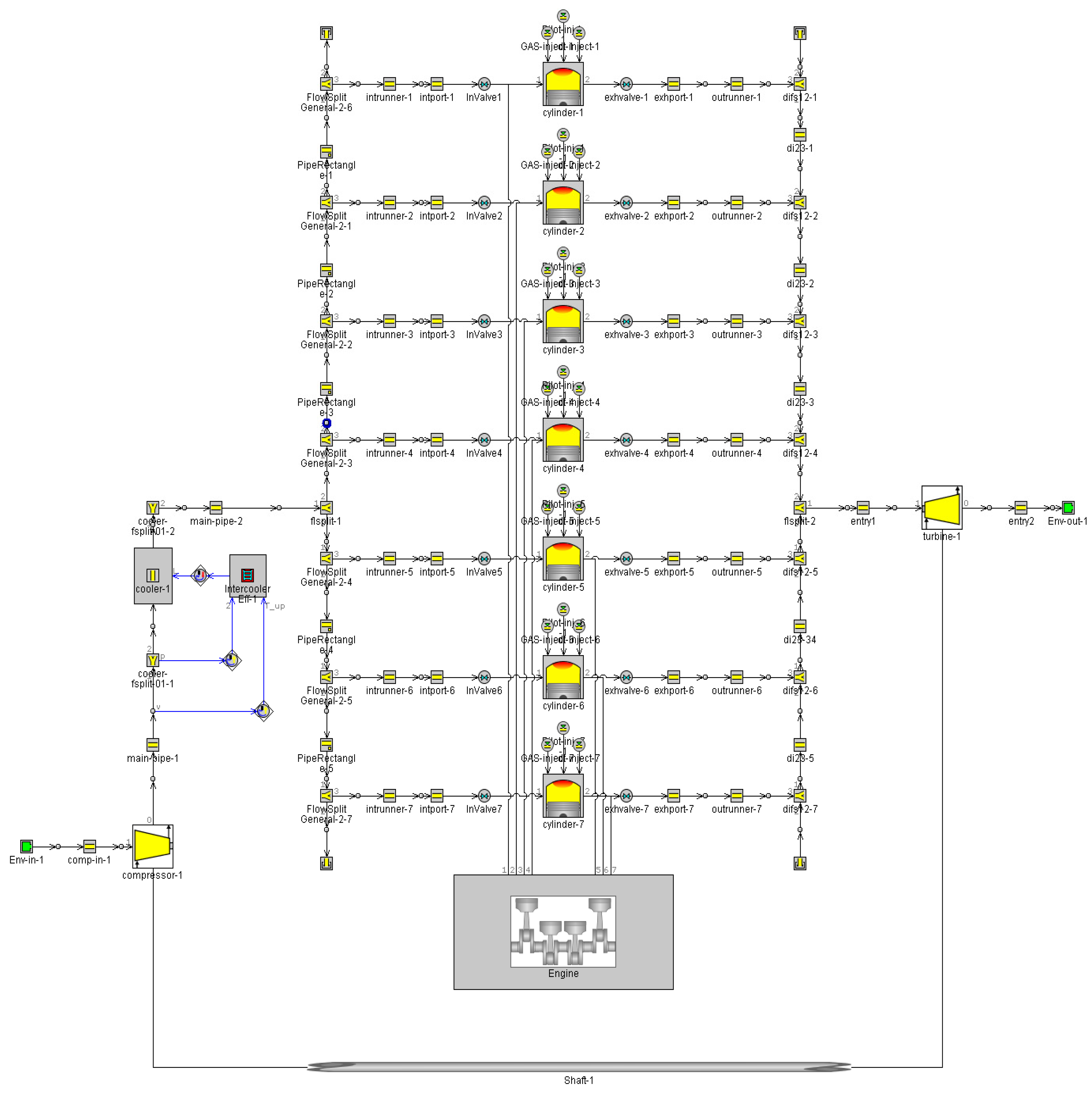
The GT Power model, built according to the principal structure of the dual-fuel engine, is shown in Figure 2. The built model mainly includes the intake and exhaust modules, fuel supply module, cylinder module, supercharger module, and crankcase module of the dual-fuel engine.
The link between the GT Power model and the Simulink model is realized through the control module in GT Power. When performing coupled simulation calculations, the engine model built with GT Power will be used as the engine module in the Simulink model for calculations. A part of the simulation results will be output directly from Simulink, and the rest of the calculation results will be viewed from GT Power. The established joint simulation model is shown in Figure 3.

2.6. Simulation Model Calibration

To simulate this transient process of fuel-mode switching in a dual-fuel engine, the accuracy of the simulation model in steady-state operation at a certain power should be ensured first. The accuracy of the simulation calculation under steady-state conditions of the engine model is necessary to ensure the accuracy of the simulation calculation during the transient process of fuel-mode switching. So, this paper calibrates the engine model running in gas and diesel modes, respectively, for different loads combined with bench reports. In this paper, the load is based on the maximum continuous rating (MCR) of the engine that allows long-term continuous operation at the calibrated speed. The exhaust temperature in this article refers to the temperature of the exhaust gas behind the cylinder.
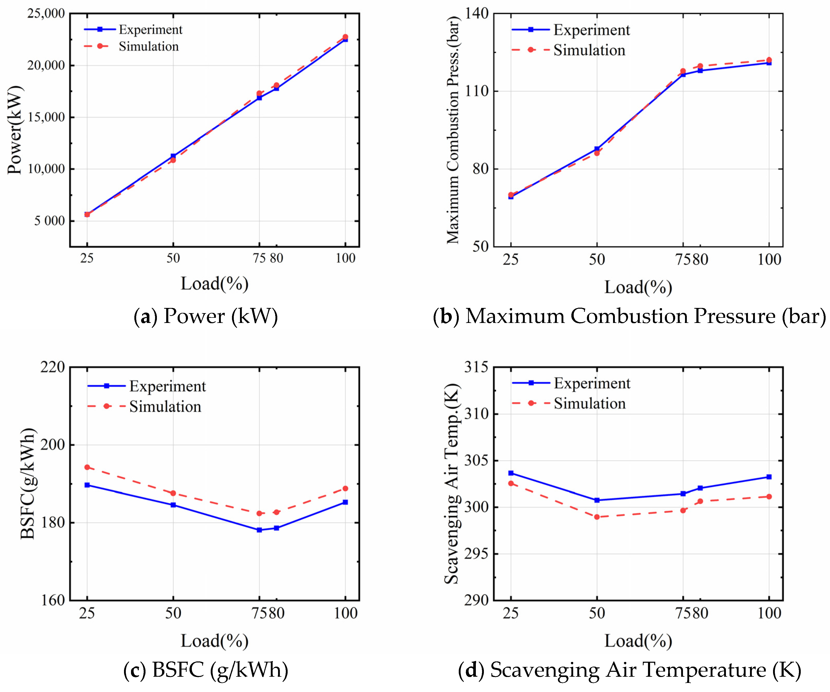
Combined with the shipyard bench report, Figure 4 shows the comparison of the main simulation parameters and experimental parameters under different loads in diesel mode.
As seen from Table 4, the simulation model of the whole engine system of the dual-fuel main engine in the complete diesel operation mode is not very different from the data in the test report in terms of power, fuel consumption rate, exhaust temperature, and other performance parameters. The simulation results of power, fuel consumption rate, exhaust temperature, and other performance parameters of the dual-fuel main engine are not much different from the data in the test report, and the relative errors are less than 5%.
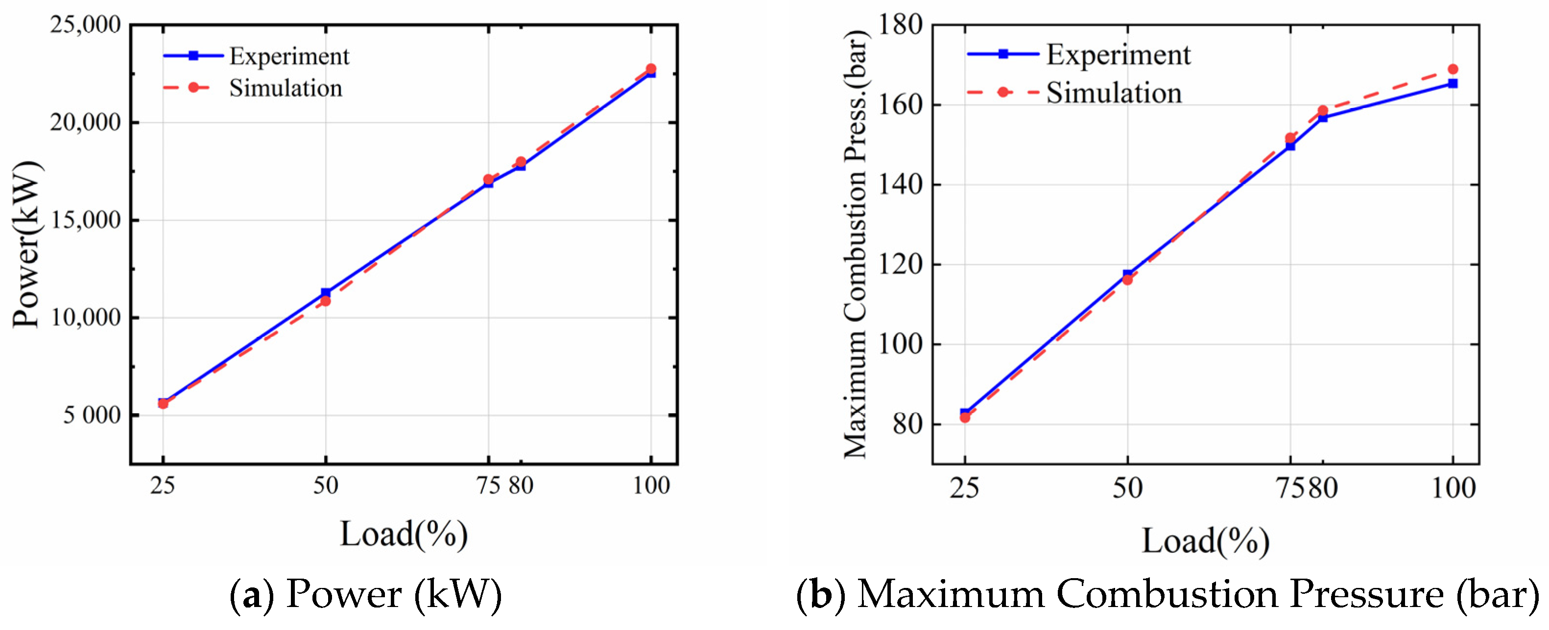
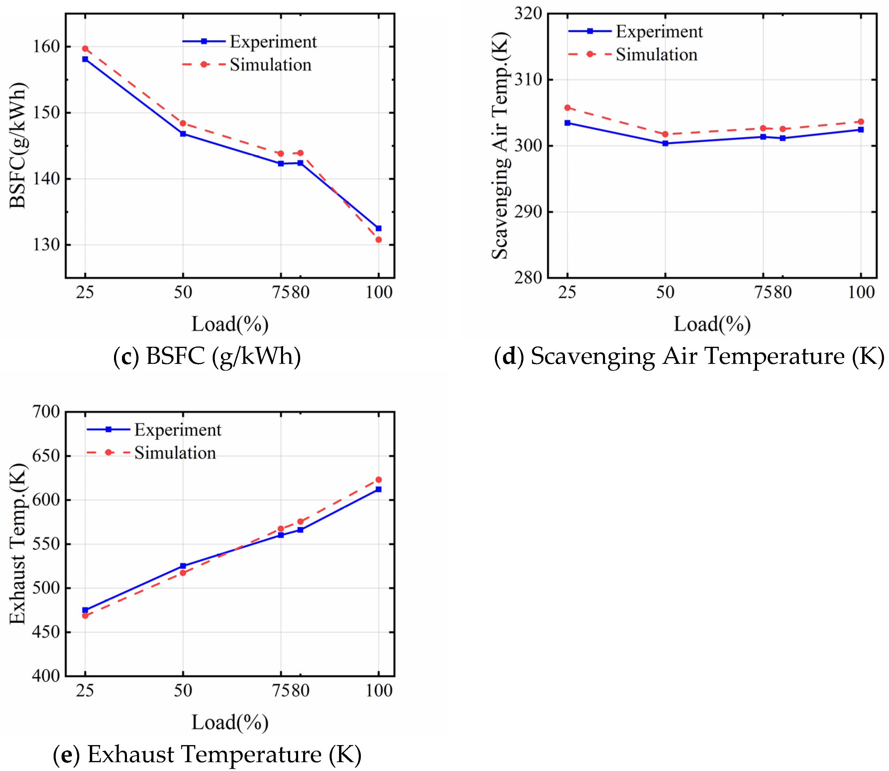
Combined with the shipyard bench report, Figure 5 shows the comparison of the main simulation parameters and experimental parameters under different loads in gas mode.
As seen from Table 5, the simulation model of the whole engine system of the dual-fuel main engine in the complete diesel operation mode is not very different from the data in the test report in terms of power, fuel consumption rate, exhaust temperature, and other performance parameters. The simulation results of power, fuel consumption rate, exhaust temperature, and other performance parameters of the dual-fuel main engine are not much different from the data in the test report, and the relative errors are less than 5%.
From Table 4 and Table 5, we can conclude that the simulation errors of the main parameters of the engine are within 5% in diesel and gas modes. The results show that the developed engine model is of good accuracy and can meet the requirements for further research.

3. Simulation of a Dual-Fuel Engine Fuel-Mode Switching Process

Load is one of the judgment signals for the choice of running a dual-fuel engine in diesel mode or gas mode. According to the engine operation manual, for the sake of engine safety operation, the dual-fuel main engine can realize the transient switch from diesel mode to gas mode when the engine load is below 80%, and the switch from gas mode to diesel mode can be carried out under any load condition.
In this section, the transient process of fuel-mode switching at an 80% fixed load is simulated using the built dual-fuel engine model, and the results are analyzed.

3.1. Switching from Gas Mode to Diesel Mode

This section of the simulation experiment is a transient operation simulation of switching a dual-fuel main engine from gas to diesel mode by controlling the supply of model fuel when the dual-fuel engine runs at 80% load.
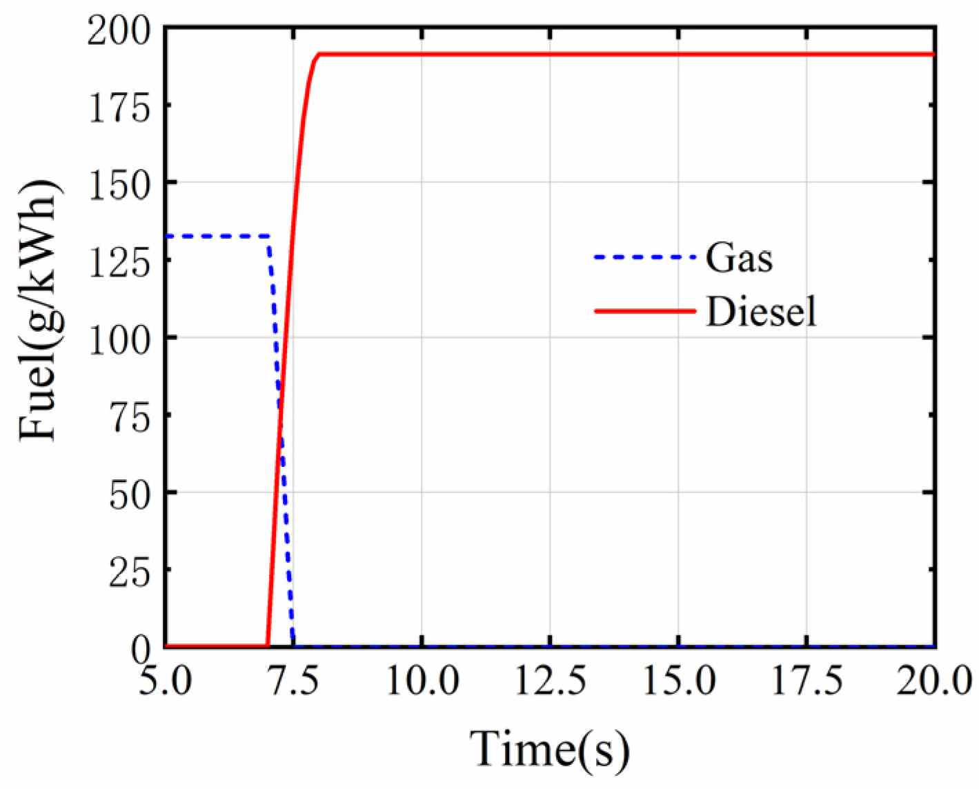
The fuel change curve for the input model is shown in Figure 6.
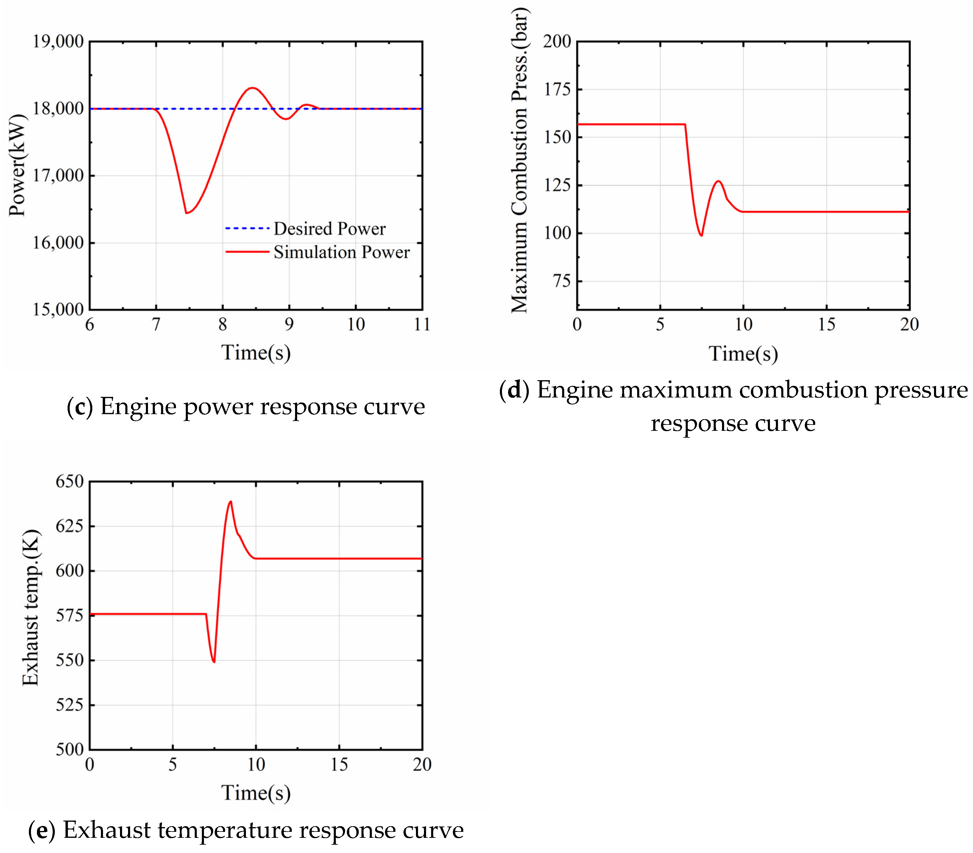
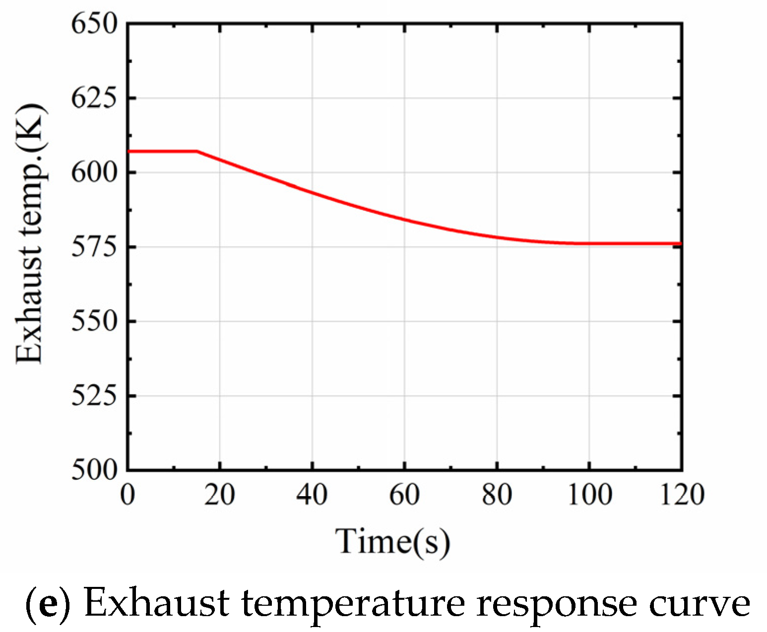
The engine performance parameter response curve for this transient process is shown in Figure 7:
As shown in Figure 7, the gas fuel is completely cut off by 7.4 s into the simulation. Although the control system quickly increases the diesel supply, this fuel supply process cannot be completed instantaneously, which leads to a lack of power in the engine cylinders during the cycle, which in turn leads to a drop in instantaneous engine speed. This process also leads to a reduction in the exhaust gas temperature. Because the reduction in speed causes the control system to control a rapid increase in diesel supply, the engine speed will recover rapidly, and a degree of overspeed will occur. This overshoot will result in higher exhaust gas temperatures. High exhaust gas temperatures are a dangerous situation for the main engine and can lead to an increased heat load on the relevant thermal components of the engine. Especially when other engine components are degraded, such as turbocharger component fouling, the phenomenon can even lead to crankcase explosions in severe cases. These adverse effects can significantly reduce the safety and power of the main engine, as well as increase engine maintenance work.
During the engine switchover from gas to diesel mode, the engine initially operates in gas mode. There is a certain lag in the fuel supply system at the start of the switchover, which causes the engine to be underpowered at this moment in time. Then, to restore the engine’s temporarily lost power and speed, the fuel supply system experiences an oversupply of fuel. As the fuel switchover proceeds, the engine operating conditions gradually return to steady-state values, and the engine performance parameters stabilize. As shown in Figure 7, the maximum speed drop during the engine changeover from gas to diesel mode is less than 5%, and the engine speed reaches a steady state about 3 s after the start of the fuel changeover. This meets the manufacturer’s requirements of less than 10% change in engine speed and less than 5 s recovery time during fuel-mode changeover.

3.2. Switching from Diesel Mode to Gas Mode

This section of the simulation experiment is a transient operation simulation of switching a dual-fuel main engine from diesel to gas mode by controlling the supply of model fuel when the dual-fuel engine runs at 80% load.
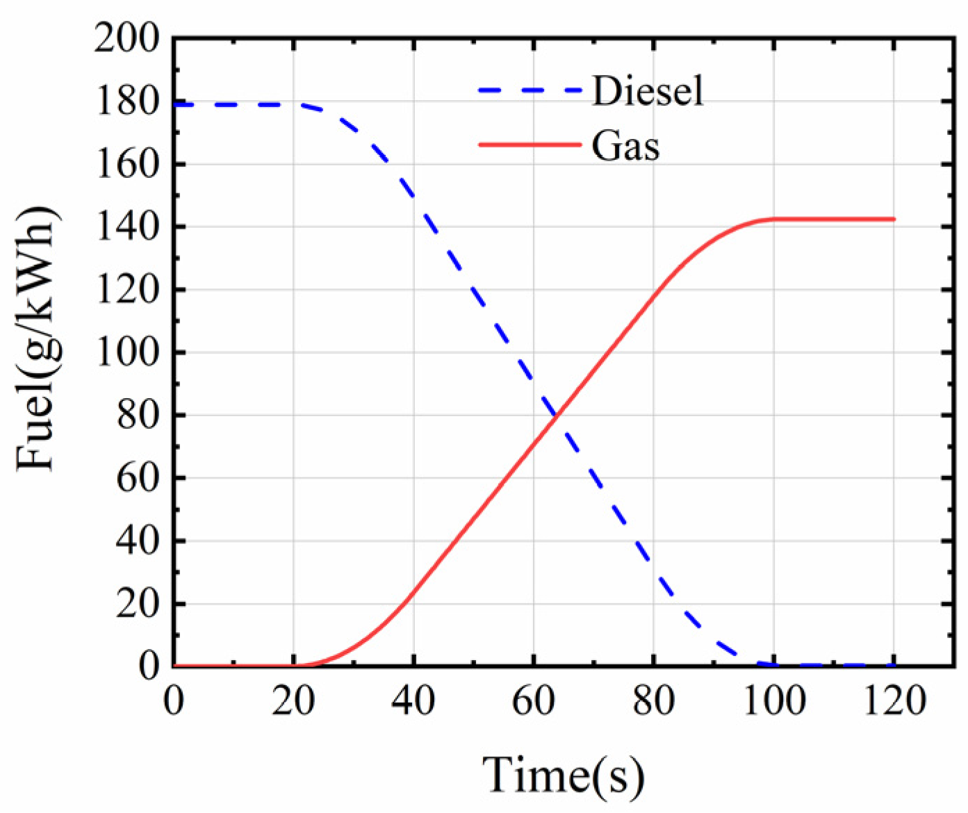
The fuel change curve for the input model is shown in Figure 8.
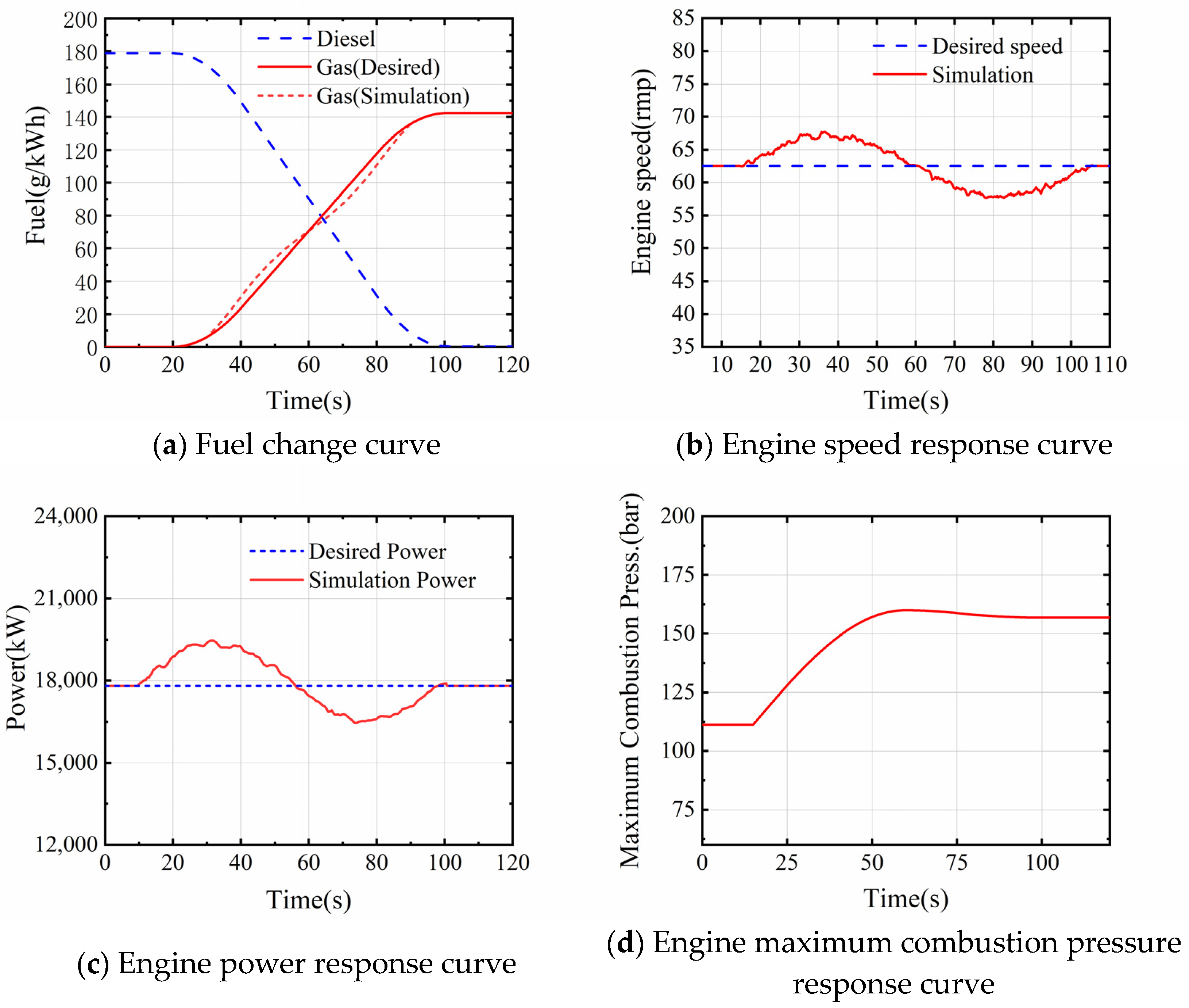
The engine performance parameter response curve for this transient process is shown in Figure 9:
As shown in Figure 9, the engine speed shows a relatively smooth change during the switch from diesel to gas mode operation until it reaches a steady-state value at the end of the switch. The entire fuel changeover process is completed in 2 min, which is much slower than the changeover from gas to diesel mode. As a result, the engine runs more smoothly throughout the switching process, and there are no significant spikes in speed fluctuations. It can be inferred from this that the mechanical and thermal loads on the engine components during the changeover are smoother than during the changeover from gas to diesel mode and that the probability of failure and safety incidents is lower.
As shown in the simulation results in Figure 9, the changeover from diesel to gas mode is completed within 2 min after the start of the fuel-mode switching operation, and the speed fluctuation is less than 10%. This meets the manufacturer’s requirement that the changeover from diesel to gas mode operation be completed within 2 min and that the speed error is less than 10% of the rated speed.

4. Cuckoo-Search-Algorithm-Based Control Parameter Tuning

4.1. Cuckoo Search Algorithm

In nature, the cuckoo has a particular egg-laying habit, called parasitic egg-laying, and its trajectory to find the nests of other birds conforms to the Levy flight characteristics, which, under random conditions, enables a significant increase in the efficiency of the search for resources in an uncertain environment. The cuckoo search algorithm uses Levy flight characteristics to optimize global search [31]. It has the advantages of being relatively simple to implement, having fewer parameters, excellent search paths, easy convergence to the optimal global solution, and easy integration with other algorithms [32,33,34,35,36].
The cuckoo search algorithm, in its modeling of the cuckoo’s nesting process, considers that its nesting process satisfies the following three ideal assumptions [35,36,37]:
(a)
The cuckoo chooses a random nest location and lays only one egg in a single nest at a time.
(b)
Eggs in the better-placed nests will be kept and hatched.
(c)
The number of nests available to cuckoos and the probability that each nest owner will find an intrusive egg is fixed.
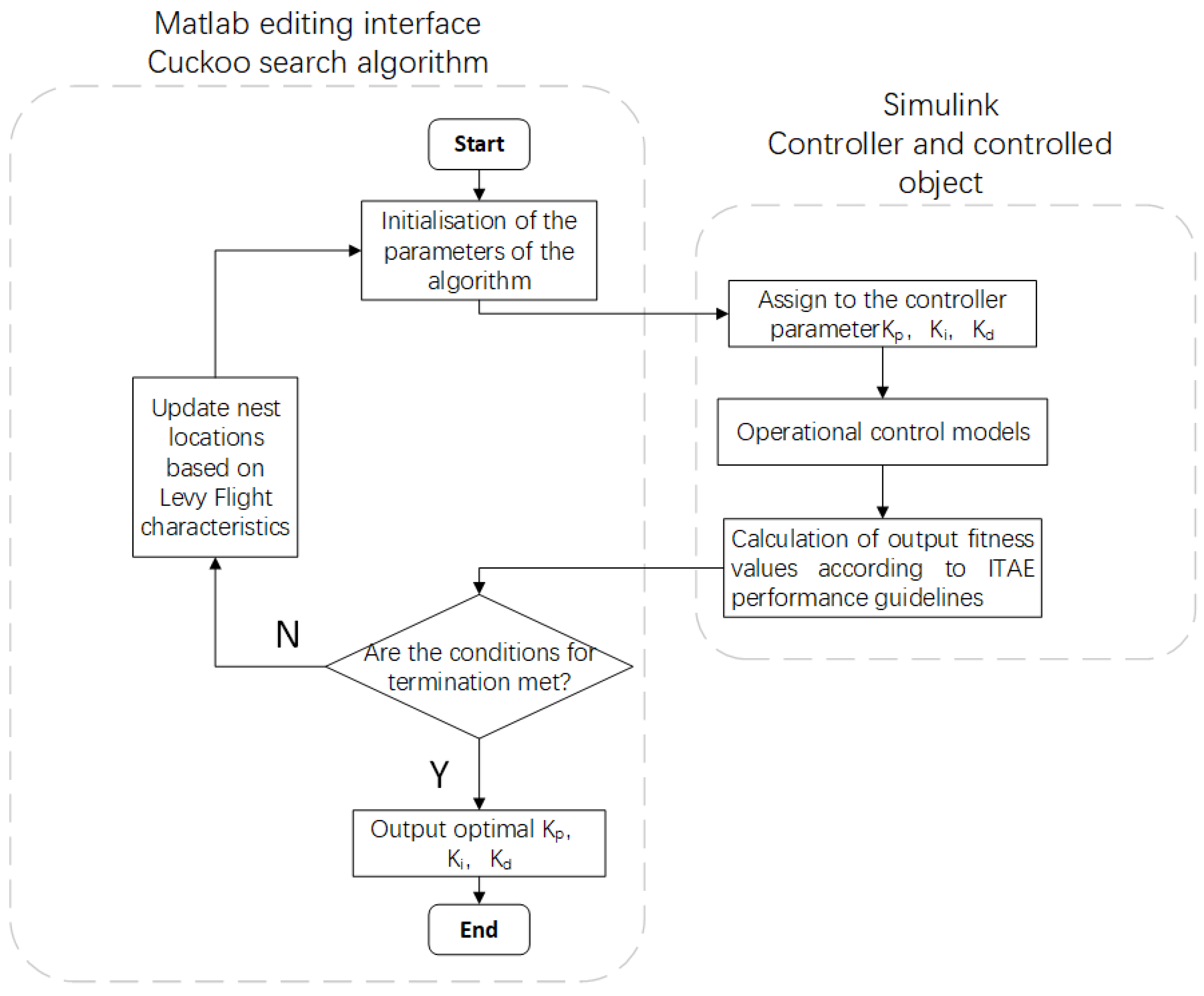
The cuckoo search algorithm is used to optimize the parameters of the fuel supply system controller, which is to determine a set of suitable controller parameters to make the system meet certain transient and steady-state response requirements. In other words, if the fuel supply system can be regarded as a function to be solved, then adjusting the parameters of the controller is equivalent to seeking a set of optimal solutions of the function, which correspond to the parameters of the controller. Furthermore, the value of the function of the system meets the requirements of the appropriate fitness function value, so that the performance of the fuel supply system to meets the desired requirements [38,39].
In this paper, the time-multiplied absolute error integration (ITAE) criterion is chosen as the fitness function for the parameter tuning of the fuel supply system controller. The smaller the value of the ITAE criterion, the more effective the parameters [40]. The selected ITAE criterion is used as the fitness function, as in Equation (13):
J = 0 t | e ( t ) | d t
where J is the fitness function value and e ( t ) is the difference between the target value and the measured value.
Implementation of the cuckoo search algorithm [41]:
(a)
The initial definition of the algorithm parameters: for the number of nests, Q, the larger the Q, the greater the number of nest options for the cuckoo to lay eggs; in this paper, Q = 500. The problem dimension, H, also known as the number of optimization parameters, is the three control parameters in the controller; in this paper, H is taken as 3, 2, and 1 in this order. The discovery probability, Pa, refers to the likelihood of the original nest owner finding exotic cuckoo eggs; in this paper Pa = 0.25. The number of iterations is C; in this paper C = 100. The nest’s location is randomly initialized, and the fitness function is defined.
(b)
The fitness function values for each existing nest location are calculated and compared with each other to select the current optimal function value.
(c)
In addition to the optimal nest, the nest location and nest state are updated using Levy flight for the other nest locations while generating a random number of r(r ∈ [0,1]).
(d)
The value of the function calculated in step (c) is compared with the optimal function value in step (b) to generate a new optimal function value. The random number r generated in step (c) is compared with the discovery probability, Pa, defined in step (a). If r > Pa, a new nest position is generated randomly; otherwise, the nest position remains unchanged. In addition, add one to the number of iterations.
(e)
If the maximum number of iterations set in step (a) has been met, the global optimal nest position is output at that point; if the maximum number of iterations is not satisfied, return to step (c).
The process of optimizing the control parameter adjustment based on the cuckoo algorithm is shown in Figure 10.

4.2. Simulation Verification of PID Parameter Tuning Based on the Cuckoo Search Algorithm

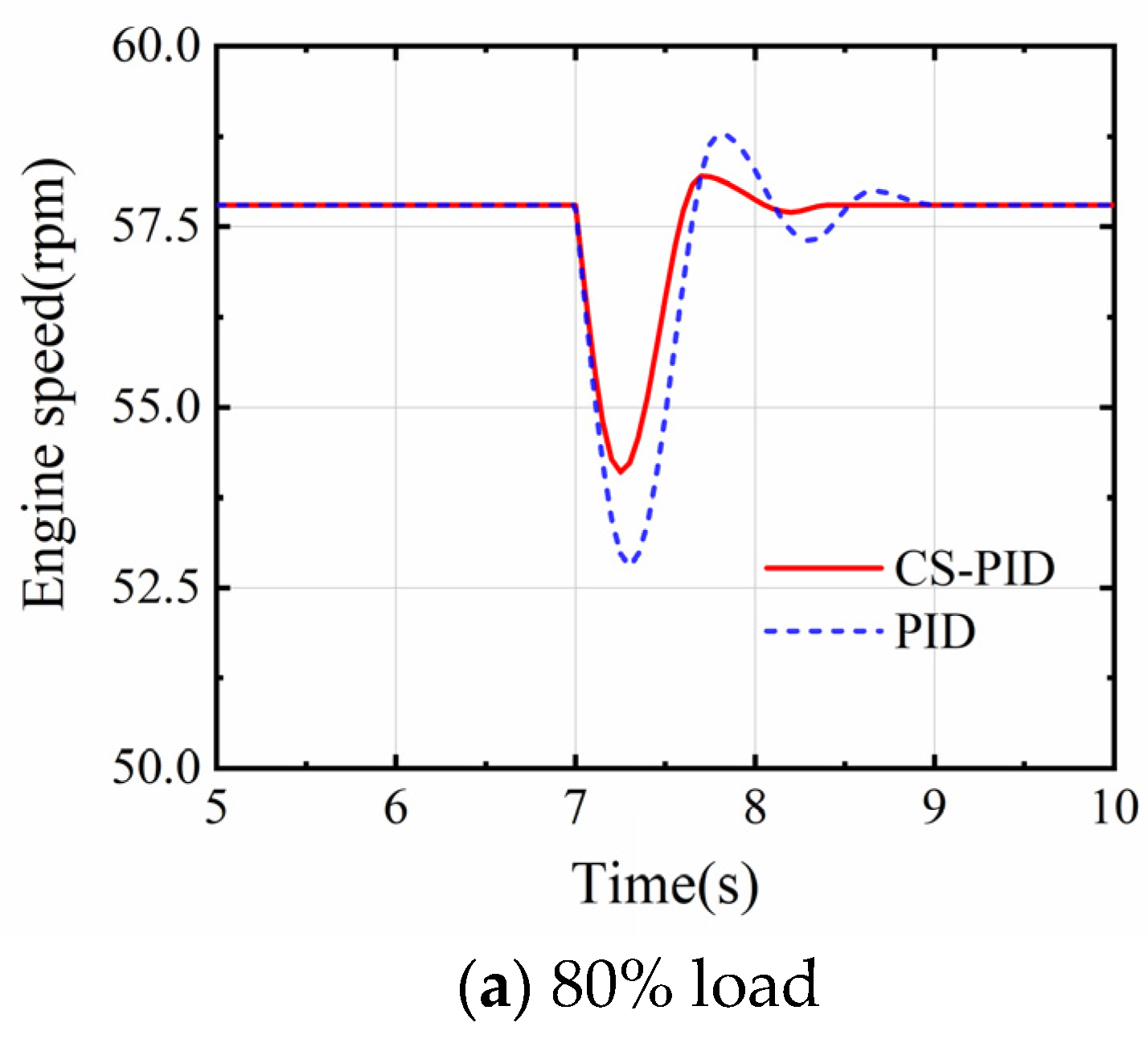
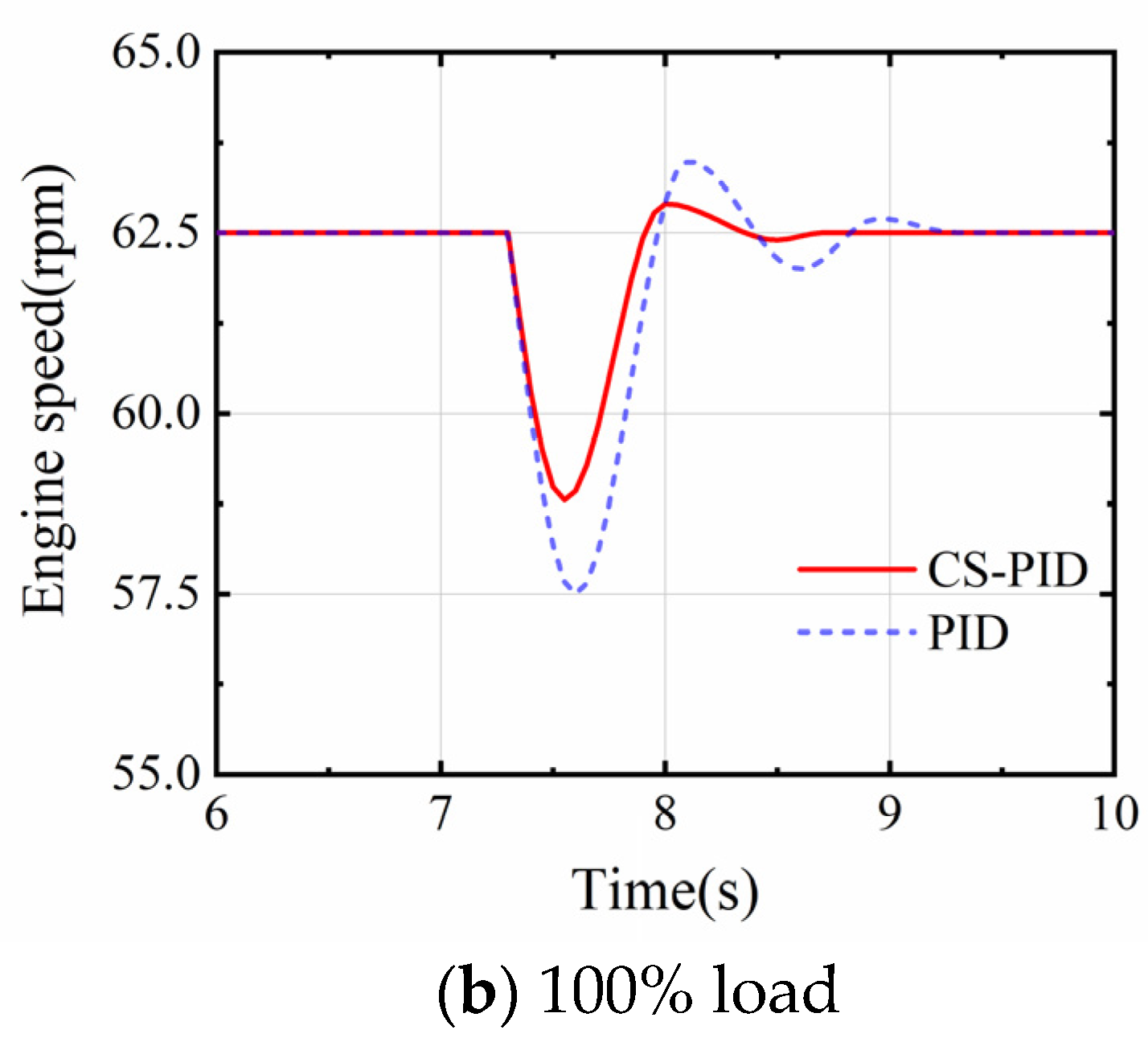
This section conducts simulation experiments by allowing the main engine to run at 80% and 100% load operating conditions and switching from gas to diesel mode operation. The effect of the PID controller based on the cuckoo search algorithm is verified by comparing the change in engine speed during fuel-mode switching. The response curve of the dual-fuel main engine speed is shown in Figure 11.
As shown in Figure 11, we can see that the speed of the main engine fluctuates less and reaches a steady state more quickly than with a conventional PID controller. The simulation results show that the PID controller based on the cuckoo search algorithm proposed in this paper can effectively and speedily suppress the speed fluctuations of the dual-fuel mainframe during fuel-mode switching and make the mainframe transition more smoothly and safely.

5. Conclusions

In this paper, a simulation model of a large, marine, two-stroke dual-fuel engine was built using GT Power and MATLAB/Simulink coupling, mainly including the engine thermodynamic model and the functional model of the engine control system. The transient process of mode switching of the engine was studied using it. Based on the simulation result analysis, the control system’s PID control parameters were adjusted based on the cuckoo search algorithm and applied to the simulation model to verify its control effect. The main contents of this paper are summarized as follows:
  • A simulation model of the 7X82DF dual-fuel engine was built using GT Power and MATLAB/Simulink coupling. The model was calibrated and verified by using the steady-state data of the engine running in diesel and gas modes and the bench report provided by the shipyard. Each error was within 5%, which verified the model’s accuracy. It was demonstrated that the developed model met the requirements for further research.
  • According to the manufacturer’s requirements, the engine needs to be switched from running in gas mode to diesel mode within 2 s, which places high demands on the engine and its control system. The rapid cut-off of the gas and the lag in the diesel supply cause an instantaneous lack of engine power, which results in an instantaneous drop in engine speed. In order to quickly restore engine power and speed, the control system increases the diesel supply and overshoots the speed, after which the engine gradually stabilizes. This process is more prone to safety accidents as the engine speed fluctuates due to the short switching time and the high mechanical and thermal loads on the engine components.
  • The changeover from diesel to gas mode is longer, and the change in fuel supply is smoother, so the simulation gives a smoother transition in engine parameters. The changeover process is less volatile and less demanding on the engine and its control system than the changeover from gas to diesel mode. Therefore, the possibility of a safety incident during this process is also low.
  • The cuckoo search algorithm was introduced and used to optimize the parameters of a PID controller for a conventional fuel supply system. The optimized controller is then used to simulate the switching process from gas to diesel mode at 80% and 100% loads on the main engine. The results show that the optimized controller is able to significantly suppress the engine speed fluctuations when performing the fuel-mode switch.
In summary, the developed simulation model can be used as a direction and reference for the next steps in engine development and optimization, and the control model’s design. The simulation results obtained using the model reveal the operating characteristics of a large, marine, dual-fuel engine during the transient process of fuel-mode switching. The simulation results, combined with the optimized control system, can provide the basis for designing new fuel-mode switching control strategies to ensure smooth and safe engine operation.

Author Contributions

Conceptualization, Z.S. and H.G.; methodology, Z.S.; software, Z.S.; validation, Z.S., H.G. and Z.J.; formal analysis, H.G.; investigation, Z.S. and B.L.; resources, H.G.; data curation, H.G.; writing—original draft preparation, Z.S.; writing—review and editing, H.G. and Z.J.; visualization, H.G.; supervision, H.G.; project administration, H.G.; funding acquisition, H.G. All authors have read and agreed to the published version of the manuscript.

Funding

The research work has been financially supported by the National Natural Science Foundation of China (grant number U1905212), as well as “the Fundamental Research Funds for the Central Universities” (grant number 3132019315).

Institutional Review Board Statement

Not applicable.

Informed Consent Statement

Not applicable.

Data Availability Statement

Not applicable.

Acknowledgments

The authors also gratefully acknowledge the helpful comments and suggestions of the reviewers, which have improved the presentation of this paper.

Conflicts of Interest

The authors declare no conflict of interest.

Nomenclature

PIDProportion Integral Differential
CSCuckoo search algorithm
LNGLiquefied natural gas
IMOInternational Maritime Organization
PIDProportional–Integral–Derivative controller
TDCTop dead center
ATDCAfter top dead center
t S O I Fuel inject timing
t I D Ignition delay time
PPressure in the cylinder
TTemperature in the cylinder
kChemical kinetic rate constant
mMass of oil and gas mixture generated during the ignition delay
C p r e Calibration factor
λ Taylor microscale length
f ( ) , g ( ) GT Power built-in function
V c Volume of cylinders
[ O 2 ] Concentration of oxygen
C d f Diffusion combustion coefficient
h j · d m j Energy that enters or exits the system
Q i Heat exchanged through the system boundary
WMechanical work of the gas in the cylinder acting on the piston
h j Specific enthalpy
UInternal energy of the system
VWorking volume of the air cylinder
φ Crank angle
Q W Heat enters or leaves the walls of the cylinder
Q B Heat release of fuel into the cylinder
h s , h e Specific enthalpy at the intake valve and exhaust valve
m s , m e Mass of the working substance flowing into and out of the cylinder
m B Instantaneous fuel mass in the cylinder
VVolume of the working substance in the system
nAmount of substance of the working substance in the system
TTemperature of the working substance in the system
RGas constant
m ˙ Mass flow through the control body boundary
ρ Density
AArea cross section
uVelocity of the working substance crossing the boundary
A s Surface area of the heat transfer surface
eInternal energy per unit mass
HEnthalpy per unit mass
hHeat transfer coefficient
T f l u i d , T w a l l Temperature of the fluid and the temperature of the wall
C p Pressure loss coefficient
C f Surface friction coefficient
dxMass element length in the flow direction
dpPressure difference before and after dx
DEquivalent diameter
Y ( t ) Output value
e ( t ) Difference between the target value and the measured value
K p Proportionality coefficient
T i Integral coefficient
T d Differential coefficient
MCRMaximum continuous rating
BSFCBrake-specific fuel consumption
ITAETime-multiplied absolute error integration criterion

References

  1. Karimi, M.; Wang, X.L.; Hamilton, J.; Negnevitsky, M.; Lyden, S. Status, challenges and opportunities of dual fuel hybrid approaches-a review. Int. J. Hydrogen Energy 2021, 46, 34924–34957. [Google Scholar] [CrossRef]
  2. Iannaccone, T.; Landucci, G.; Tugnoli, A.; Salzano, E.; Cozzani, V. Sustainability of cruise ship fuel systems: Comparison among LNG and diesel technologies. J. Clean. Prod. 2020, 260, 121069. [Google Scholar] [CrossRef]
  3. Thomson, H.; Corbett, J.J.; Winebrake, J.J. Natural gas as a marine fuel. Energy Policy 2015, 87, 153–167. [Google Scholar] [CrossRef] [Green Version]
  4. Abadie, L.M.; Goicoechea, N. Powering newly constructed vessels to comply with ECA regulations under fuel market prices uncertainty: Diesel or dual fuel engine? Transp. Res. Part D-Transp. Environ. 2019, 67, 433–448. [Google Scholar] [CrossRef]
  5. Boeckhoff, N.; Heider, G.; Hagl, P. Operational experience of the 51/60 DF from MAN Diesel SE. In Proceedings of the 26th CIMAC World Congress on Combustion Engine Technology, Bergen, Norway, 10–14 June 2019. Paper No. 37. [Google Scholar]
  6. Xianquan, Z.; Jianguo, Y.; Lufeng, H.; Shulin, Z.; Zhengyan, Q. Experimental research of fuel mode switch-over for a marine micro-pilot-ignition dual-fuel engine. J. Harbin Eng. Univ. 2021, 42, 541–547. [Google Scholar]
  7. Enzhe, S.; Zhongzhou, J.; Chong, Y.; Guofeng, Z. Research on Mode Switch Control Strategy of Marine Diesel/Natural Gas Dual Fuel Engine. J. China Mech. Eng. 2022, 33, 388–396. [Google Scholar]
  8. Reitz, R.D.; Ogawa, H.; Payri, R.; Fansler, T.; Kokjohn, S.; Moriyoshi, Y.; Agarwal, A.K.; Arcoumanis, D.; Assanis, D.; Bae, C.; et al. IJER editorial: The future of the internal combustion engine. Int. J. Engine Res. 2020, 21, 3–10. [Google Scholar] [CrossRef] [Green Version]
  9. Nwafor, O.M.I. Knock Characteristics of Dual-Fuel Combustion in Diesel Engines Using Natural Gas As Primary Fuel. Sadhana-Acad. Proc. Eng. Sci. 2002, 27, 375–382. [Google Scholar] [CrossRef]
  10. Srinivasan, K.K.; Krishnan, S.R.; Qi, Y.; Asme. Cyclic Combustion Variations in Dual Fuel Partially Premixed Pilot-Ignited Natural Gas Engines. In Proceedings of the ASME Internal Combustion Engine Division Spring Technical Conference, Politecn Torino, Torino, Italy, 6–9 May 2012; p. 133. [Google Scholar]
  11. Wartsila. Wartsila 31DF Product Guide [DB/OL]. [2019–3]; Wartsila: Helsinki, Finland, 2019. [Google Scholar]
  12. Stoumpos, S.; Theotokatos, G.; Mavrelos, C.; Boulougouris, E. Towards Marine Dual Fuel Engines Digital Twins—Integrated Modelling of Thermodynamic Processes and Control System Functions. J. Mar. Sci. Eng. 2020, 8, 200. [Google Scholar] [CrossRef] [Green Version]
  13. Gaurav, T.; Priybrat, S.; Atul, D. Computational study of diesel injection strategies for methane-diesel dual fuel engine. J. Clean. Eng. Technol. 2022, 6, 100393. [Google Scholar]
  14. Lounici, M.S.; Benbellil, M.A.; Loubar, K.; Niculescu, D.C.; Tazerout, M. Knock characterization and development of a new knock indicator for dual-fuel engines. Energy 2017, 141, 2351–2361. [Google Scholar] [CrossRef]
  15. Tripathi, G.; Sharma, P.; Dhar, A.; Sadiki, A. Computational investigation of diesel injection strategies in hydrogen-diesel dual fuel engine. Sustain. Energy Technol. Assess. 2019, 36, 100543. [Google Scholar] [CrossRef]
  16. Mavrelos, C.; Theotokatos, G. Numerical investigation of a premixed combustion large marine two-stroke dual fuel engine for optimising engine settings via parametric runs. Energy Convers. Manag. 2018, 160, 48–59. [Google Scholar] [CrossRef]
  17. Murphy, A.J.; Norman, A.J.; Pazouki, K.; Trodden, D.G. Thermodynamic simulation for the investigation of marine Diesel engines. Ocean Eng. 2015, 102, 117–128. [Google Scholar] [CrossRef] [Green Version]
  18. Stoumpos, S.; Theotokatos, G.; Boulougouris, E.; Vassalos, D.; Lazakis, I.; Livanos, G. Marine dual fuel engine modelling and parametric investigation of engine settings effect on performance-emissions trade-offs. Ocean Eng. 2018, 157, 376–386. [Google Scholar] [CrossRef] [Green Version]
  19. Sui, W.B.; Gonzalez, J.P.; Hall, C.M. Combustion Phasing Modelling of Dual Fuel Engines. In Proceedings of the 5th International-Federation-of-Automatic-Control (IFAC) Conference on Engine and Powertrain Control, Simulation and Modeling (E-COSM), Changchun, China, 20–22 September 2018; pp. 319–324. [Google Scholar]
  20. Xu, S.N.; Anderson, D.; Hoffman, M.; Prucka, R.; Filipi, Z. A phenomenological combustion analysis of a dual-fuel natural-gas diesel engine. Proc. Inst. Mech. Eng. Part D-J. Automob. Eng. 2017, 231, 66–83. [Google Scholar] [CrossRef]
  21. Tang, J.; Zhu, G.M.G.; Men, Y. Review of engine control-oriented combustion models. Int. J. Engine Res. 2022, 23, 347–368. [Google Scholar] [CrossRef]
  22. Kwak, K.H.; Borgnakke, C.; Jung, D.; Asme. Fuel sensitive ignition delay models for a local and global description of direct injection internal combustion engines. In Proceedings of the ASME Internal Combustion Engine Division Fall Technical Conference, Columbus, IN, USA, 19–22 October 2014. [Google Scholar]
  23. Ma, F.K.; Zhao, C.L.; Zhang, F.J.; Zhao, Z.F.; Zhang, Z.Y.; Xie, Z.Y.; Wang, H. An Experimental Investigation on the Combustion and Heat Release Characteristics of an Opposed-Piston Folded-Cranktrain Diesel Engine. Energies 2015, 8, 6365–6381. [Google Scholar] [CrossRef] [Green Version]
  24. Ithnin, A.M.; Ahmad, M.A.; Abu Bakar, M.A.; Rajoo, S.; Yahya, W.J. Combustion performance and emission analysis of diesel engine fuelled with water-in-diesel emulsion fuel made from low-grade diesel fuel. Energy Convers. Manag. 2015, 90, 375–382. [Google Scholar] [CrossRef]
  25. Kang, Z.; Wu, Z.J.; Fu, L.Z.; Deng, J.; Hu, Z.J.; Li, L.G. Experimental Study of Ion Current Signals and Characteristics in an Internal Combustion Rankine Cycle Engine Based on Water Injection. J. Eng. Gas Turbines Power-Trans. ASME 2018, 140, 111506. [Google Scholar] [CrossRef]
  26. Chalet, D.; Chesse, P.; Hetet, J.F. Boundary conditions modelling of one-dimensional gas flows in an internal combustion engine. Int. J. Engine Res. 2008, 9, 267–282. [Google Scholar] [CrossRef]
  27. Yu, R.; Bai, X.S. A semi-implicit scheme for large Eddy simulation of piston engine flow and combustion. Int. J. Numer. Methods Fluids 2013, 71, 13–40. [Google Scholar] [CrossRef]
  28. Qinghua, S.; Dandan, W. Neural Network Ship PID Control and Simulation Based on Grey Prediction. J. Coast. Res. 2020, 110, 299–303. [Google Scholar]
  29. Nakatani, T.; Ohtsu, K.; Okazaki, T.; Moriyoshi, N. On Automatic Tuning of Ship’s PID Regulators. Trans. Soc. Instrum. Control. Eng. 1998, 34, 689–691. [Google Scholar] [CrossRef]
  30. Shen, X.Q.; Su, Y.X. Marine Diesel Engine Speed Control System Based on Fuzzy-PID. In Proceedings of the International Conference on Mechanical Engineering and Materials (ICMEM), Melbourne, Australia, 15–16 January 2012; pp. 1589–1594. [Google Scholar]
  31. Yang, X.S.; Deb, S. Cuckoo Search via Levey Flights. In Proceedings of the World Congress on Nature and Biologically Inspired Computing, Coimbatore, India, 9–12 December 2009; p. 210. [Google Scholar]
  32. Soneji, H.; Sanghvi, R.C. Towards the Improvement of Cuckoo Search Algorithm. In Proceedings of the World Congress on Information and Communication Technologies (WICT), Trivandrum, India, 30 October–2 November 2012; pp. 878–883. [Google Scholar]
  33. Boeckhoff. Operational Experience of the 51/60 DF from MAN Diesel SE. In Proceedings of the 26th CIMAC World Congress on Combustion Engine Technology, Bergen, Norway, 14–15 May 2010; pp. 1867–1872. [Google Scholar]
  34. Das, S.; Dasgupta, P.; Panigrahi, B.K. Inter-species Cuckoo Search via Different Levy Flights. In Proceedings of the 4th International Conference on Swarm, Evolutionary, and Memetic Computing (SEMCCO), SRM Univ., Chennai, India, 19–21 December 2013; pp. 515–526. [Google Scholar]
  35. Gandomi, A.H.; Yang, X.S.; Alavi, A.H. Cuckoo search algorithm: A metaheuristic approach to solve structural optimization problems. Eng. Comput. 2013, 29, 17–35. [Google Scholar] [CrossRef]
  36. Tang, H.L.; Xue, F. Cuckoo search algorithm with different distribution strategy. Int. J. Bio-Inspired Comput. 2019, 13, 234–241. [Google Scholar] [CrossRef]
  37. Quoc, H.D.; The, L.N.; Doan, C.N.; Thanh, T.P.; Ieee. New Cuckoo Search Algorithm for the Resource Constrained Project Scheduling Problem. In Proceedings of the RIVF International Conference on Computing and Communication Technologies (RIVF), RMIT University, Ho Chi Minh City, Vietnam, 14–15 October 2020; pp. 376–378. [Google Scholar]
  38. Mudi, R.K.; Pal, N.R. A robust self-tuning scheme for PI- and PD-type fuzzy controllers. IEEE Trans. Fuzzy Syst. 1999, 7, 2–16. [Google Scholar] [CrossRef] [Green Version]
  39. Gozde, H.; Taplamacioglu, M.C.; Kocaarslan, I. Comparative performance analysis of Artificial Bee Colony algorithm in automatic generation control for interconnected reheat thermal power system. Int. J. Electr. Power Energy Syst. 2012, 42, 167–178. [Google Scholar] [CrossRef]
  40. Maurya, A.K.; Bongulwar, M.R.; Patre, B.M.; Ieee. Tuning Of Fractional Order PID Controller For Higher Order Process Based On ITAE Minimization. In Proceedings of the 12 IEEE International C Elect Energy Environmental Communications Computer Control, New Delhi, India, 17–20 December 2015. [Google Scholar]
  41. Jin, Q.B.; Qi, L.F.; Jiang, B.Y.; Wang, Q. Novel improved cuckoo search for PID controller design. Trans. Inst. Meas. Control. 2015, 37, 721–731. [Google Scholar] [CrossRef]
Figure 1. Structure and working principle of dual-fuel main engine.
Jmse 10 02004 g001
Figure 2. 7X82DF simulation model in GT Power.
Jmse 10 02004 g002
Figure 3. Co-simulation model.
Jmse 10 02004 g003
Figure 4. Comparison of simulation and experiment in diesel mode.
Jmse 10 02004 g004aJmse 10 02004 g004b
Figure 5. Comparison of simulation and experiment in gas mode.
Jmse 10 02004 g005aJmse 10 02004 g005b
Figure 6. Fuel change curve.
Jmse 10 02004 g006
Figure 7. The response curve of engine performance parameter.
Jmse 10 02004 g007aJmse 10 02004 g007b
Figure 8. Fuel change curve.
Jmse 10 02004 g008
Figure 9. The response curve of engine performance parameter.
Jmse 10 02004 g009aJmse 10 02004 g009b
Figure 10. Schematic diagram of the process of optimizing and controlling the parameters of the cuckoo search algorithm.
Jmse 10 02004 g010
Figure 11. Comparison of engine speed response curves.
Jmse 10 02004 g011aJmse 10 02004 g011b
Table 1. Dual-fuel engine main parameters.
Engine ParametersUnitValues
Cylinder-7
Boremm820
Strokemm3375
Compression ratio-12.4
PowerkW22,531
Speedrpm62.5
Firing order-1-6-3-4-5-2-7
Pilot-injection pressurebar755
Gas-injection pressurebar14.8
Pilot timing°CA ATDC−8.5
Gas-valve timing°CA ATDC224
Table 2. Pilot consumption in diesel mode.
Load (%)25507580100
Pilot
consumption (g/kWh)
1.00.50.40.30.3
Table 3. Pilot consumption in gas mode.
Load (%)25507580100
Pilot
consumption (g/kWh)
1.90.40.30.30.3
Table 4. Calculation errors of parameters in diesel mode.
Load (%)25507580100
Error (%)
Power (kW)−0.267−3.5562.5181.8281.133
Maximum Combustion Pressure (bar)1.154−1.9361.2011.5250.909
BSFC (g/kWh)2.4251.6252.4142.2951.889
Scavenging Air Temperature (K)−0.362−0.599−0.597−0.463−0.692
Exhaust Temperature (K)1.357−1.0031.2310.9881.4
Table 5. Calculation errors of parameters in gas mode.
Load (%)25507580100
Error (%)
Power (kW)−0.781−3.7591.1241.2891.025
Maximum Combustion Pressure (bar)−1.445−1.1911.3361.1482.178
BSFC (g/kWh)1.0121.0891.0541.623−0.128
Scavenging Air Temperature (K)0.7580.4660.4310.4650.397
Exhaust Temperature (K)−1.378−1.4851.2851.6601.781
Publisher’s Note: MDPI stays neutral with regard to jurisdictional claims in published maps and institutional affiliations.