Article

Research on Maneuverability Prediction of Double Waterjet Propulsion High Speed Planing Craft

1
College of Shipbuilding Engineering, Harbin Engineering University, Harbin 150001, China
2
College of Marine Engineering, Jimei University, Xiamen 361026, China
*
Author to whom correspondence should be addressed.
J. Mar. Sci. Eng. 2022, 10(12), 1978; https://doi.org/10.3390/jmse10121978
Submission received: 6 November 2022 / Revised: 4 December 2022 / Accepted: 8 December 2022 / Published: 12 December 2022
(This article belongs to the Section Ocean Engineering)

Abstract

:
A mathematical model for predicting the maneuvering motion of a ship is constructed, using a planing craft with dual waterjet propulsion as the object of study. This model is based on the standard approach of the MMG (Maneuvering Modeling Group) and uses the Runge–Kutta algorithm to solve the differential equations. For the simulation of the turning and Z-shape maneuvering motion, the RANS equation is first solved using the program STAR-CCM + and then the PMM motion of the hull is simulated using the overlapping grid approach to derive the hydrodynamic derivative. The established method for predicting the ship’s maneuverability is feasible, as shown by the calculated results, which agree well with those obtained using data from the sea trials. This method was used to simulate the rudder rotation and Z-shape motion of the planing craft at medium and high speeds to predict the maneuverability index.

1. Introduction

With its good maneuverability, the waterjet propeller has been widely used in medium and high-speed ships [1]. The waterjet propeller relies on the momentum difference between the inflow and outflow to generate thrust, which will have a significant impact on the flow around the hull. During the navigation of the high-speed ship, the hull state changes with the speed, and the interaction between the hull and the waterjet propeller is more complicated [2,3]. Aiming at the maneuverability of a water-jet propulsion ship, Jie Gong et al. studied the interaction between the water-jet device of the four-jet propulsion ship and the hull, and analyzed its influence on the propulsion performance of the ship [4]. Based on RANS solver, Jun Guo et al. numerically simulated and analyzed the self-propulsion performance of a water-jet propulsion trimaran. The MRF model was used to directly simulate the spray pump device, and the effectiveness of the numerical method was verified by comparison with experiments [5]. Lei Li et al. studied the maneuverability of the double waterjet propulsion boat, simulated the boat in different operating conditions, and verified the excellent maneuverability of the waterjet propulsion system [6]. Xu Zijing et al. studied the maneuverability of a double waterjet propulsion ship, and simulated the rotary test and Z-shaped test based on simulink, which verified the feasibility of applying this method to maneuverability prediction [7]. Ye Luo et al. simulated the rotational motion of impeller in a waterjet by the MRF (multiple reference frame) method and analyzed the flow field characteristics. It has been demonstrated that the accuracy achieved by this method is ideal in predicting hydrodynamics and torque. When the waterjet propeller is opened, the lateral force on the hull increases and the longitudinal force and yaw moment are reduced. The results of the pressure distribution at the bottom and stern of the ship, the waveform of the free surface of the stern, and the velocity distribution of the wake field also show the influence of the waterjet on the flow field [8]. Jun Wang et al. used the RANS method and the VOF algorithm to calculate the two-phase flow of the rudder, obtained the flow field at different rudder angles, and analyzed the steering flow field to obtain the mechanical properties of the steering and deflection mechanism of the waterjet propulsion system [9].
At present, there are few calculations and simulations that comprehensively consider the influence of the interaction between waterjet propeller and high-speed ship on ship maneuverability, mainly relying on the test method. Yoshihiro Ikeda and Katayama from Osaka Prefectural University conducted a large number of tests using 64-series ship models, including plane motion mechanism tests, to study the instability of large pitch and heave caused by the periodic maneuvering motion of the planing hull, and to study the interaction between the waterjet and the hull [10]. Shaodan Xia et al., using plane motion mechanism (PMM), carried out model tests of ship maneuverability hydrodynamic coefficients with water jet propulsion device and bare hull tests under the same working conditions. The influence of waterjet propulsion on the navigational stability of ships is summarized by comparing the variation of hydrodynamic coefficients of different maneuvering capabilities, and important influencing factors are found [11]. Based on URANS, Tomohiro Takai et al. conducted self-propulsion numerical simulation analysis and verification of a four-jet pump high-speed ship, and optimized the inlet pipe [12].
It can be seen that the research on the maneuverability of water-jet propulsion ships at home and abroad mainly focuses on performance analysis and optimization of the water-jet propulsion device, the regression formula of hydrodynamic derivatives and the instability analysis under high-speed conditions. The research on the motion prediction of medium and high-speed ships with needle-jet propulsion devices under various operating conditions is still relatively scant, and the related theoretical research and many practical problems need to be further addressed.
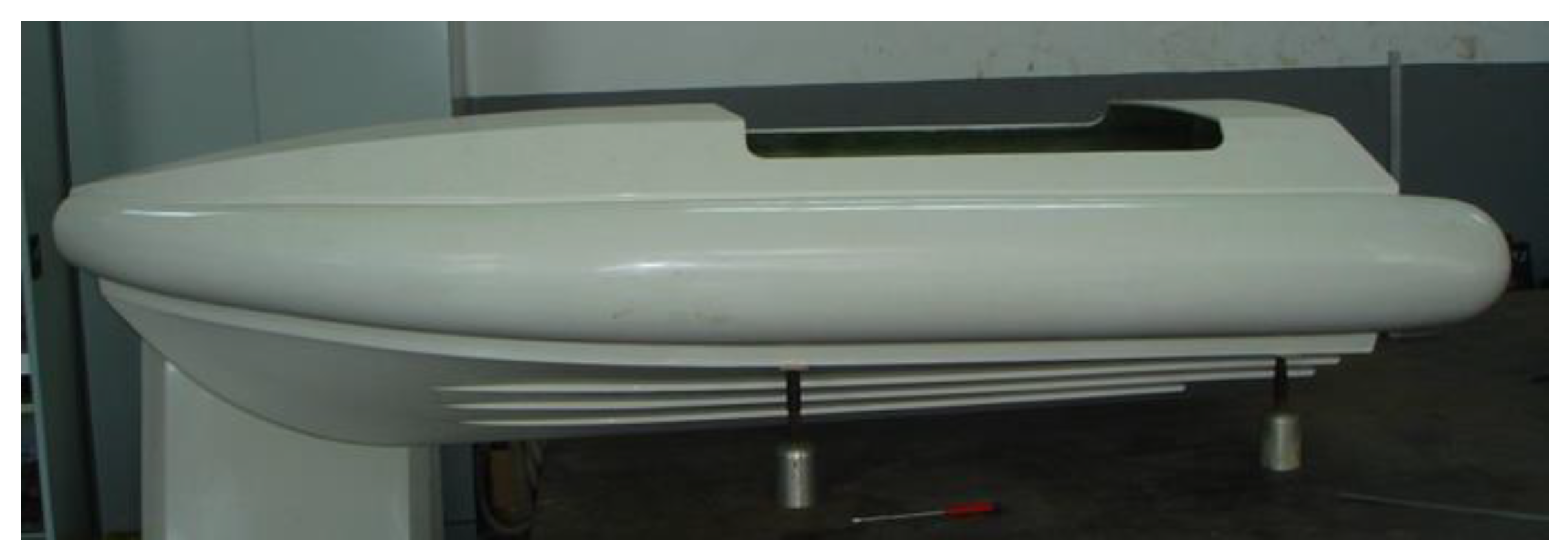
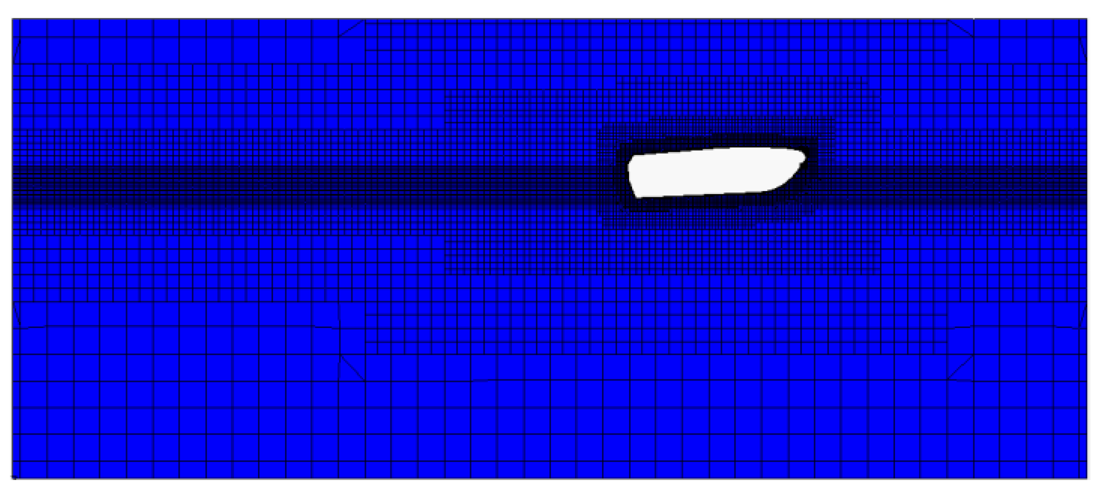
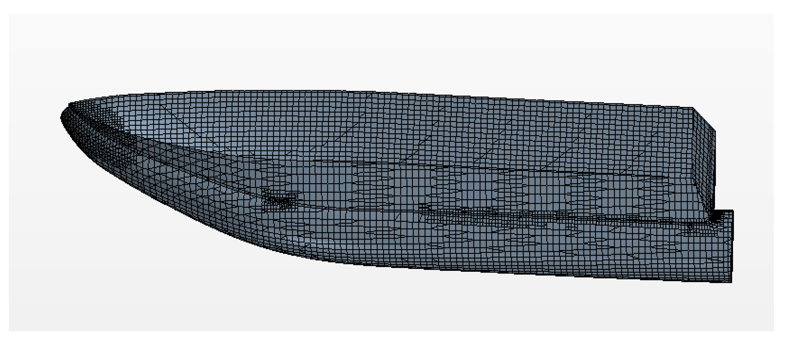
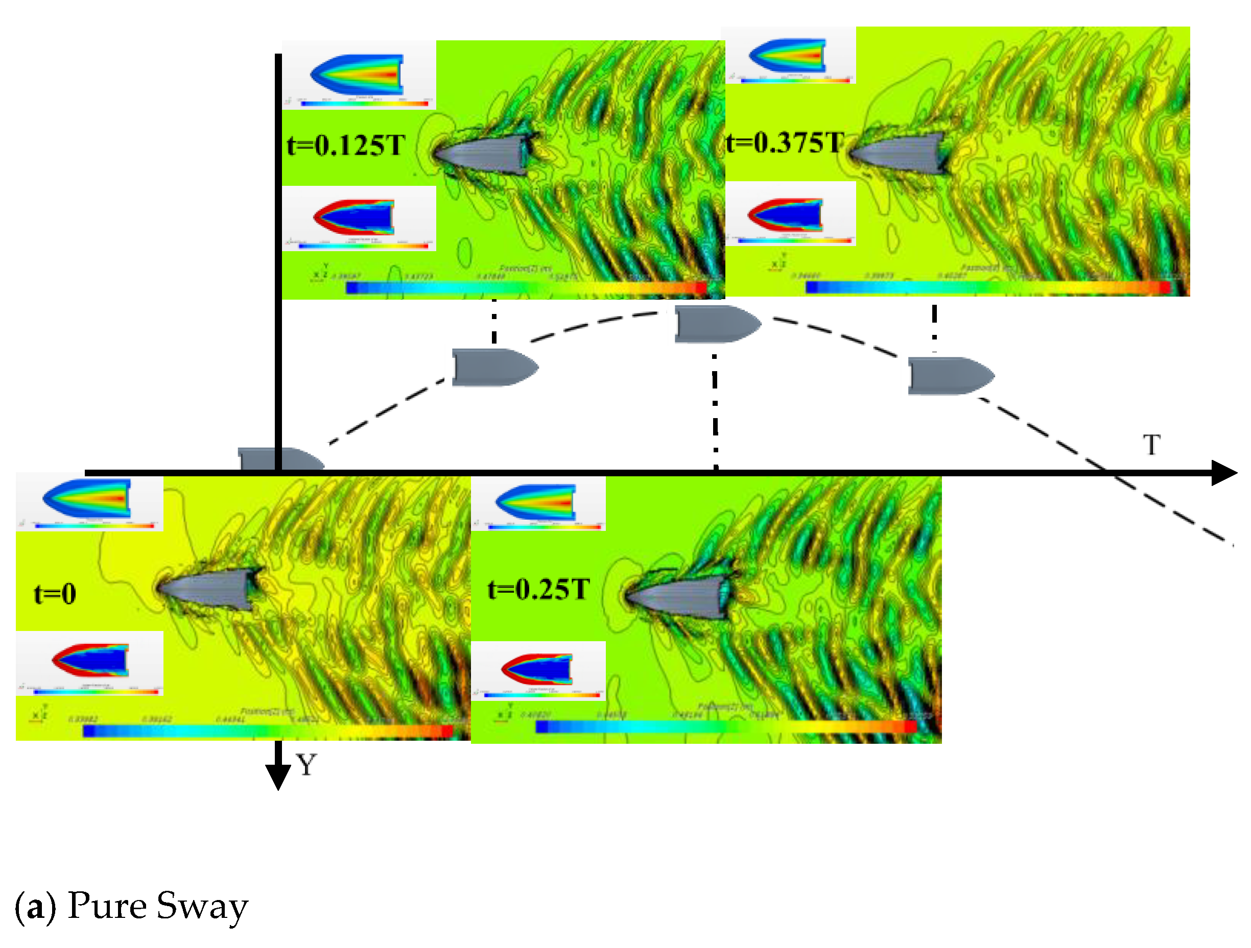
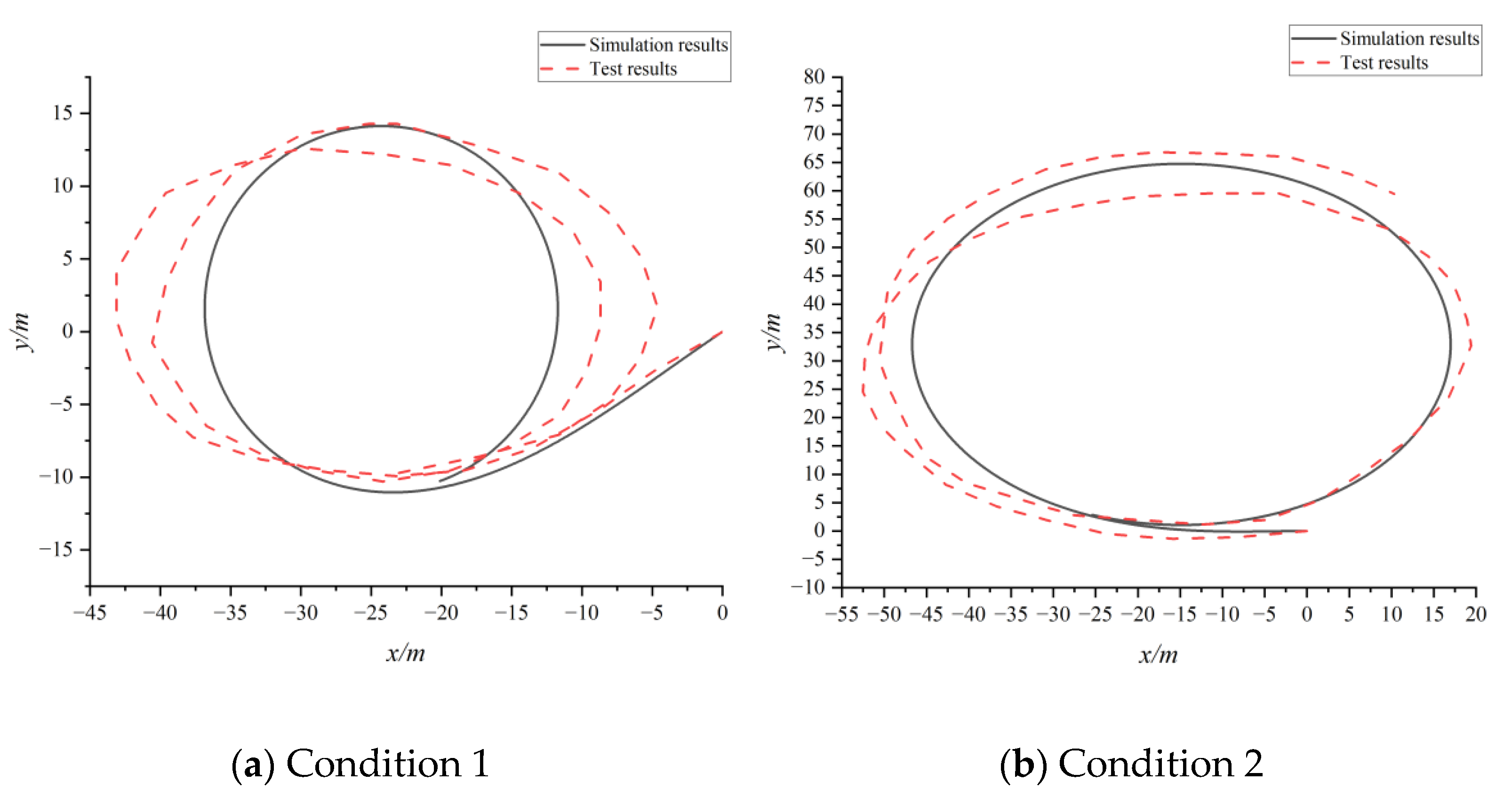
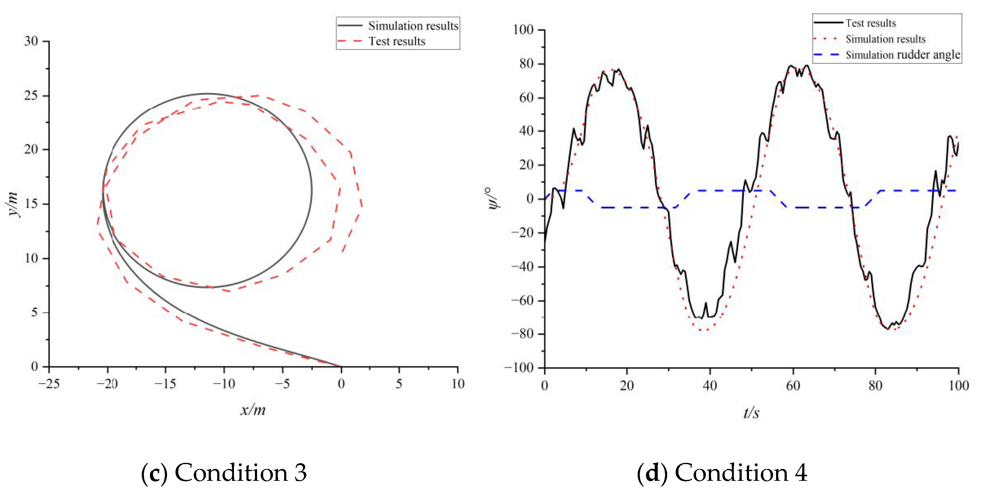
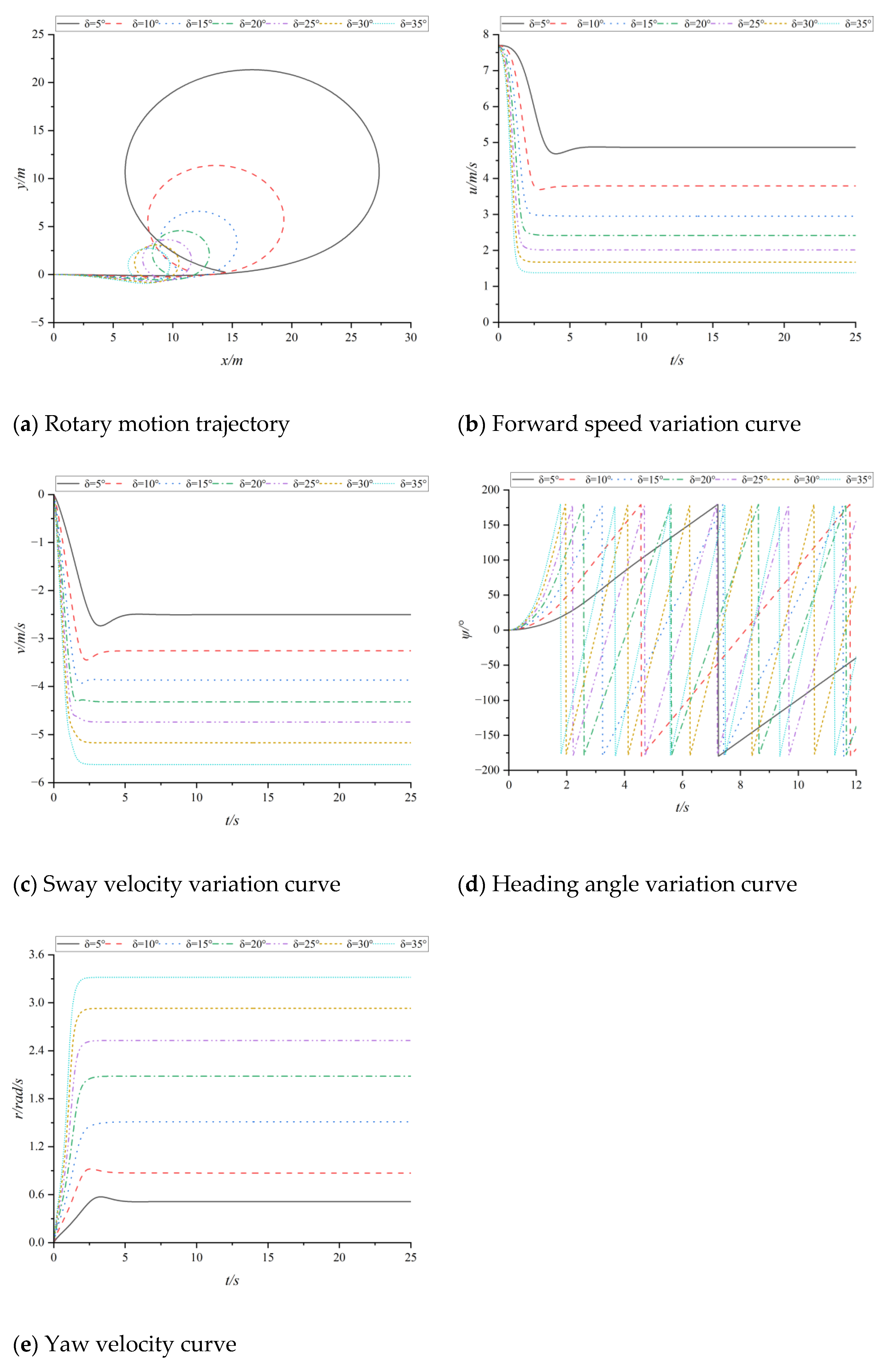
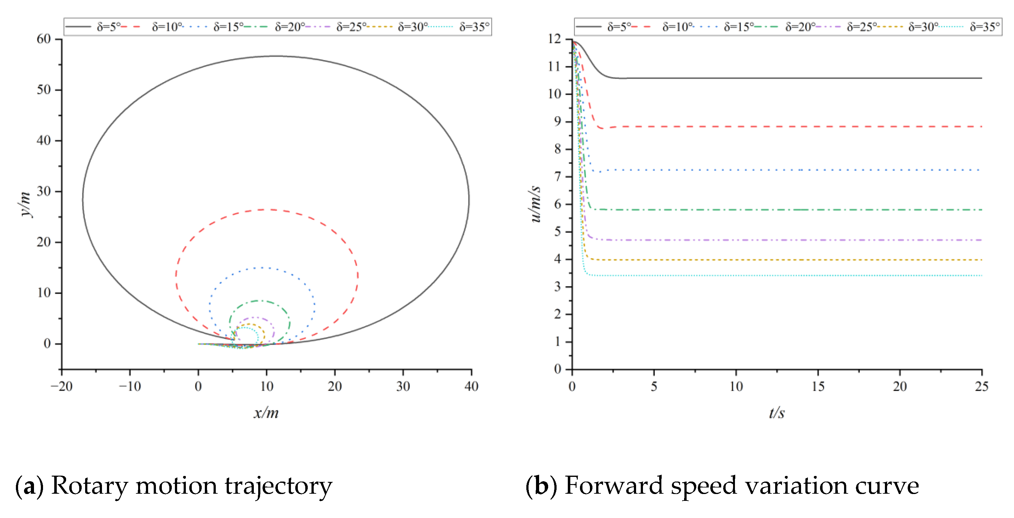
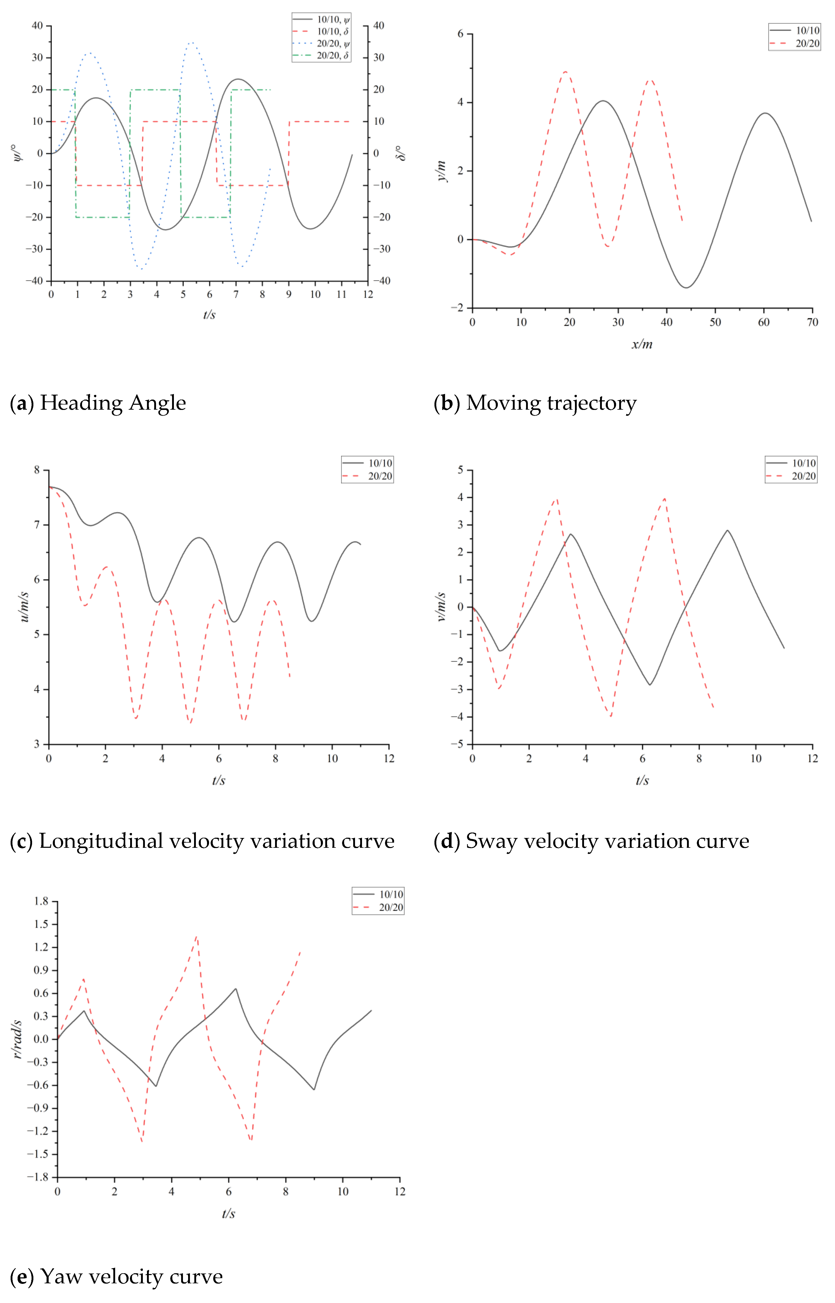
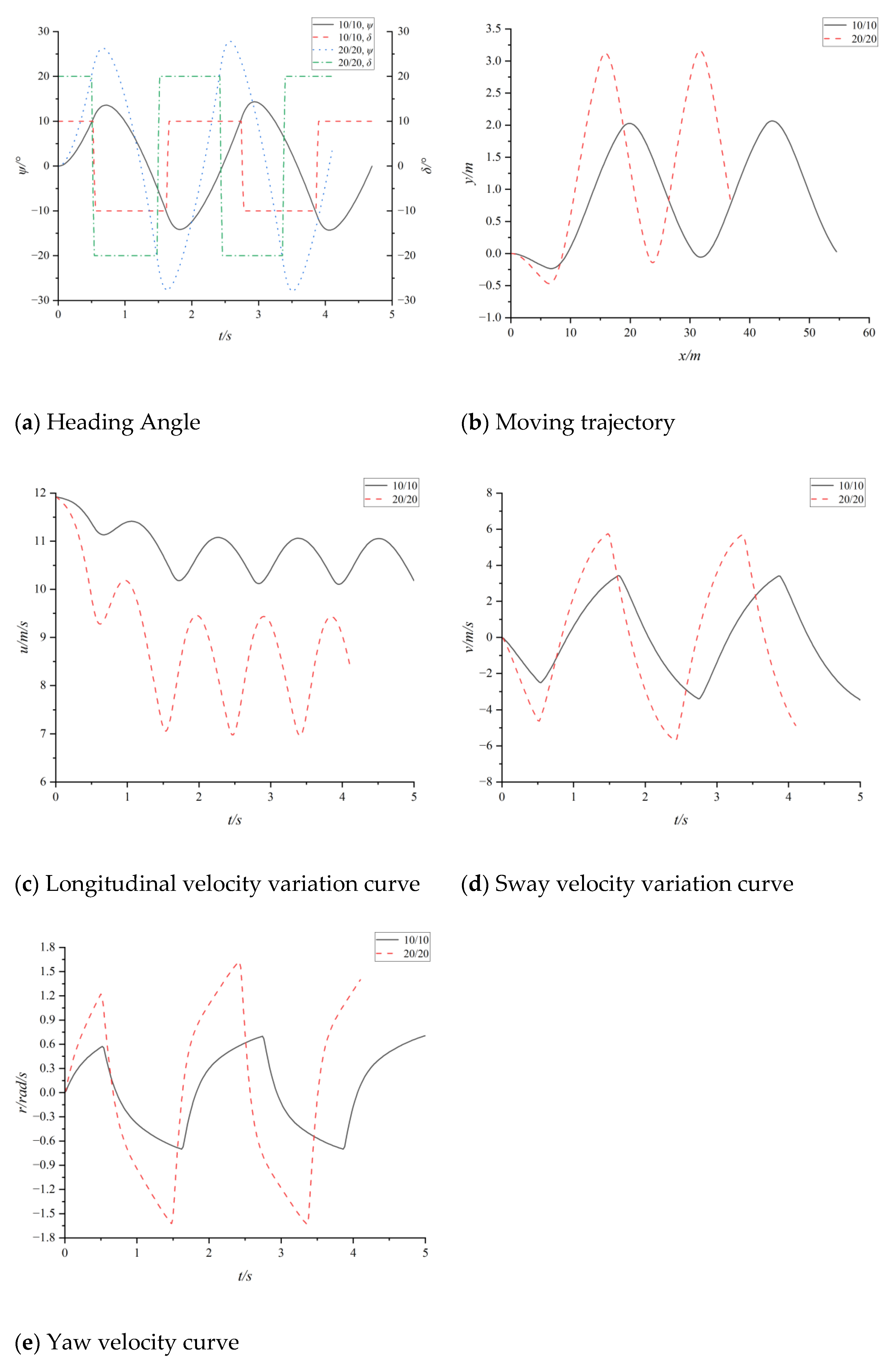
Therefore, it is of great practical significance to study the maneuvering motion prediction of high-speed ships in waterjet propulsion. In order to simulate and forecast the planing boat’s maneuvering capabilities, the MMG motion mechanism model is established in this paper with a focus on the high-speed sailing state of a double-water-jet propelled high-speed planing boat. The hydrodynamic derivative of the hull is then obtained by CFD numerical calculation while taking into account the water-jet propulsion force.

2. Mathematical Calculation Model

2.1. Coordinate

The calculation model in this paper adopts the following coordinate system, as shown in Figure 1. Under the fixed coordinate system Oo-XoYoZo, Oo is a sea level reference point, the OoXo-axis points to the initial heading, the OoYo-axis points to the right, and the OoZo-axis points to the center of the earth according to the right-hand rule. Under the ship coordinate system o-xyz, O is the position of the ship’s center of gravity, the ox-axis points to the bow along the middle line of the ship, the oy-axis points to the starboard, and the oz-axis points to the bottom of the ship.

2.2. Mathematical Model of Manipulation Motion

The relationship between the position coordinate change in the ship’s inertial coordinate system and the velocity in the ship’s coordinate system can be expressed as a function of the heading angle ψ, namely:
{ x ˙ = u cos ψ v sin ψ y ˙ = u sin ψ + v cos ψ ψ ˙ = r
where u is the longitudinal speed of the ship; v is the transverse velocity of the ship, and r is the velocity of the ship’s bow angle; ψ is the heading angle of the ship; x and y are the longitudinal and transverse coordinates of the ship, respectively.
According to the velocity and force relationship of the ship in the ship coordinate system, the separated MMG hydrodynamic model is established according to the momentum theorem and the momentum moment theorem of the relative center of mass. The external force (moment) in the equation is expressed as the component of each degree of freedom.
According to the navigation characteristics of the double waterjet propulsion planing boat, the force of the ship is analyzed in detail, and the hydrodynamic model of the double waterjet propulsion planing boat is established, which is simplified and obtained.
{ ( m + m x ) u ˙ ( m + m y ) v r = X H + X ( m + m y ) v ˙ ( m + m x ) u r = Y H + X ( I Z Z + J Z Z ) r ˙ = N H + N
{ X H = X ( u ) + X v r v r + X r r r 2 + X v v v 2 Y H = Y v v + Y v v v v 3 + Y r r + Y r r r r 3 + Y v r r v r 2 + Y v v r v 2 r N H = N v v + N v v v v 3 + N r r + N r r r r 3 + N v r r v r 2 + N v v r v 2 r
where the sum of the forward thrust of the waterjet propeller on the planing boat is X, the sum of the lateral thrust is Y, and the sum of the gyroscopic moment is N, while XH, YH and NH are the hydrodynamic forces (moments) acting on different degrees of freedom of the hull. Respectively, m is the hull mass; IZZ is the moment of inertia of the hull mass around the z-axis; mx and my are the additional masses of the hull in the x-axis and y-axis directions, JZZ is the additional inertial mass of the hull rotating around the z-axis; X(u) is the resistance of the hull during direct navigation; Xvv, Xrr, Xvr, Yv, Yr, Yvvv, Yrrr, Yvrr, Yvvr, Nv, Nr, Nvvv, Nrrr, Nvrr, Nvvr are dynamic and moment derivatives of viscous fluid.

2.3. Mathematical Model of Waterjet Propulsion

In order to determine the values of the main forces X, Y and N, a mathematical model of the waterjet propulsion force is established.
The longitudinal force on the hull is
X = ρ Q ( v j cos δ u )
The lateral force on the hull is
Y = ρ Q ( v j sin δ v )
The rotational moment of the hull with respect to the center of gravity is
N = Y L
where L is the transverse distance from the nozzle center to the ship’s center of gravity G; ρ is the density of water; Q is the pump flow; v j is the nozzle flow rate; δ is the rudder angle. Substituting (3)–(6) into (2) produces the model of the manipulation mechanism.
{ ( m + m x ) u ˙ ( m + m y ) v r = X ( u ) + X v r v r + X r r r 2 + X v v v 2 + X ( m + m y ) v ˙ + ( m + m x ) u r = Y v v + Y v v v v 3 + Y r r + Y r r r r 3 + Y v r r v r 2 + Y v v r v 2 r + Y ( I Z Z + J Z Z ) r ˙ = N v v + N v v v v 3 + N r r + N r r r r 3 + N v r r v r 2 + N v v r v 2 r + Y L

2.4. Numerical Model and Method

The three-dimensional incompressible unsteady RANS method is used to calculate the hydrodynamic and flow field of the high-speed planing boat, and the governing equations are
u ¯ i x i = 0
ρ u ¯ i t + ρ u ¯ j u ¯ i x j = ρ F ¯ i p ¯ x i + x j ( μ u ¯ i x j ρ u i u j ¯ )
where u i ¯ is the hourly velocity, u i is the fluctuation velocity, ρ u i u j ¯ is Reynolds stress.
The turbulence model in numerical calculation adopts k-ε model, which is mathematically expressed as:
Turbulent kinetic energy k equation:
( ρ k ) t + x i ( ρ u i k ) = x j [ ( μ + μ t σ k ) k x j ] + G k + G b ρ ε Y M + S k
Turbulence dissipation rate ε equation:
( ρ ε ) t + x i ( ρ u i ε ) = x j [ ( μ + μ t σ ε ) ε x j ] + C 1 ε ε k ( G k + C 3 ε G b ) C 2 ε ρ ε 2 k + S ε
Here, turbulent viscosity is μ t = ρ C μ k 2 ε and the turbulent kinetic energy generation term is G k = μ t ( u i x j + u j x i ) u i x j .
The calculation domain is a cuboid, where the boundary entrance is 1.5 times the length of the ship from the bow and the boundary exit is 3.5 times the length of the ship from the stern. The upper and lower boundaries of the circumferential boundary are 4/5 times the length of the keel and 1.5 times the length of the ship, and the side boundary is 1.5 times the length of the longitudinal section of the ship.
Boundary conditions include the non-slip wall boundary condition for the planing boat’s surface, the velocity inlet boundary condition for the calculation domain’s top, bottom, and both sides, and the pressure outlet boundary condition for the calculation domain’s outlet.
The wall treatment of all y+ Wall Treatment is used in the calculation process. The convection term and time term are solved by second-order discrete format, and the free surface is captured by the Volume of Fluid (VOF) method. A numerical wave attenuation zone is set at the outlet boundary to reduce the influence of wave reflection on the calculation results.

3. Calculation Model and Example Verification of Double Waterjet Propulsion Planing Craft

3.1. Calculation Model

The research object of this paper is a high-speed planing boat, which adopts the propulsion form of a diesel engine and double waterjet propeller. The ship parameters and simplified geometric model are shown in Table 1 and Figure 2.
The grid surrounding the hull is gradually refined, as is the vertical grid near the free surface, in order to increase the hydrodynamic computational accuracy of the hull and to accurately capture the flow and wave characteristics around the hull during the motion of the planing ship. The overall meshing principle is to ensure the calculation accuracy while taking into account the calculation efficiency. The prismatic grid is set around the hull to better capture the flow details of the near-wall boundary layer. The dimensionless distance y + from the wall to the first grid is about 50. The grid division of the basin and the grid of the hull surface are shown in Figure 3 and Figure 4.

3.2. Calculation of Hydrodynamic Derivatives

The hydrodynamic derivative is obtained by the numerical simulation of the forced motion of the constraint model PMM, and the hydrodynamic force of the planing boat is obtained by the least square method [13]. The forced motion types are divided into pure sway, pure yaw and yaw with drift angle. The motion frequency ω, drift angle β and amplitude a under different working conditions are shown in Table 2; for the pure yaw and with drift angle yaw, the angle of amplitude can be further calculated according to the formula
Ψ m a x = ω a U . U = 1.513   m / s , F r = 0.1379 ( F r = v / g ^ ( 1 / 3 ) ) ^ 0.5 ,
where v is the speed, unit m/s, g is the acceleration of gravity, ▽ is the volume of drainage, unit m3). The hydrodynamic derivatives obtained by regression are shown in Table 3. Figure 5 shows the free surface wave height and the distribution of water, gas and pressure at the bottom of the ship at a typical time in a motion cycle under three kinds of forced motion. The numerical method can simulate the physical quantities near the surface of the ship. The shape and distribution of the wave at the stern and the distribution of gas, water and pressure at the bottom of the ship are consistent with the characteristics of ship motion, and the simulation effect is good.

3.3. Double Waterjet Propulsion Planing Boat Handling Simulation Verification

The sea maneuverability test of the double waterjet planing boat is carried out offshore, as shown in Figure 6. The simulation is established based on the maneuvering motion mechanism model of the medium-high speed planing boat obtained above, and the fourth-order fixed-step Runge–Kutta method is used for the numerical solution, so as to obtain the position and speed of the planing boat at any time, and then predict the maneuverability of the medium-high speed double-jet planing boat. Four typical rotary motion and Z-shaped operating conditions are selected to verify the control motion simulation, and the verification conditions are shown in Table 4. When U = 2.91 m/s, Fr = 0.2653.
Figure 7 and Table 5 give the numerical simulation results of the planing boat’s rotation and Z-shaped maneuvering under different working conditions. It is mainly the maneuverability criteria obtained by calculation and simulation that are compared, such as the rotation diameter and the first transcendental angle. The specific calculation formula is Error = (test value-simulation result)/test value. Due to the influence of wind and waves on the rotation motion test during the actual ship sea trial, the rotation circle has a tendency to drift in a certain direction. There is a certain gap between the simulation trajectory and the test trajectory, but the overall trend is consistent. The average error of the rotation diameter is within 10%, which is in good agreement. The heading angle trajectory of the Z-shaped maneuvering simulation is in good agreement with the test, and the overall change rule is consistent. The error of the first preset angle is within 1%, indicating that the simulation model can simulate the turning and Z-shaped maneuvering motion well.

4. Maneuvering Motion Simulation

Based on the verified simulation model above, the rotation and Z-shaped maneuvering motion prediction of the double waterjet propulsion planing boat under medium speed condition U1 = 7.7 m/s and high-speed condition U2 = 11.92 m/s is carried out, and the indexes of maneuverability evaluation are obtained.

4.1. Rotary Maneuvering Motion Prediction

The turning motion simulation under different rudder angles (5°–35°) is carried out to predict the maneuverability parameters of turning motion under medium and high-speed conditions. The time history curves of motion trajectory, longitudinal velocity u, lateral velocity v, heading angle ψ and turning angular velocity r under different working conditions are shown in the following Figure 8.
It can be seen from Figure 8 and Figure 9 and Table 6 that the rotary motion trajectory under different rudder angles is a series of similar ellipses. Ad (longitudinal distance), DT (tactical rotary diameter) and Do (steady rotary diameter) all decrease with the increase of rudder angle, and Tr (transverse distance) decreases with the increase of rudder angle. When the rudder angle is 25°, Tr is negative; that is, the kick appears, which increases with the increase of rudder angle. V (transverse distance) also decreases with the increase of rudder angle, the turning period decreases with the increase of rudder angle, and the lateral velocity and turning angular velocity increase with the increase of rudder angle. Under the medium speed condition, the maximum rotation diameter reaches 3.4 times the length of the ship, and the minimum is 0.6 times the length of the ship. Under the high-speed condition, the maximum rotation diameter reaches 9 times the length of the ship, and the minimum is 0.65 times the length of the ship. Under most rudder angles, the rotation diameter is below 4 times the length of the ship, so according to the criteria for maneuverability formulated by the IMO, the rotation is good [14].

4.2. Z-Shaped Maneuvering Motion Simulation

The 10/10, 20/20 Z-shaped motion simulation is carried out to predict the maneuverability parameters of the Z-shaped motion under medium and high-speed conditions, and the heading angle trajectory and the time history curve of each parameter are shown in the following Figure 10.
It can be seen from Figure 10 and Figure 11 and Table 7 that, at the same speed, the longitudinal velocity oscillates with time, and the oscillation amplitude increases with the increase of the rudder angle. The ts and the decrease with the increase of the rudder angle. The amplitude of the trajectory, lateral velocity and angular velocity increase with the increase of the rudder angle. The results of dimensionless initial turning period t a = t a U L show that the maneuverability at 20/20 is better than that at 10/10.

5. Conclusions

In this paper, a mathematical model of the maneuvering motion of a double waterjet planing boat is developed. Using regression, the hydrodynamic derivatives of the hull are determined by numerical simulations of pure sway, pure yaw, and yaw with drift. In order to simulate the turning and Z-shaped maneuvering of the planing boat, the hydrodynamic derivative is inserted into the Simulink simulation model of the maneuvering motion. The results lead to the following conclusions:
(1) The hydrodynamic force of the planing boat can be predicted more accurately using the numerical simulation approach and the maneuverable motion prediction model developed in this paper. The results of the simulation of the turning motion and the Z-shaped steering and the results of the sea test agree well. The error in the turning diameter is within 10% and the error of the first preset angle for the Z-shaped control is within 1%.
(2) In the medium and high-speed ranges, increasing the rudder angle causes the responsiveness and amplitude of the planing boat’s maneuverability to increase. It has a good maneuverability.
(3) Combining the numerical simulation method with the Simulation Model of Maneuvering Motion of Double Waterjet Planing Craft based on the MMG equation can quickly predict the maneuvering ability of the ship at the design stage, which is convenient for grasping the performance index of the ship in advance and improving the design efficiency, so the results have practical value.

Author Contributions

Conceptualization, H.-W.S. and J.-L.Y.; methodology, H.-W.S.; software, J.-F.X.; validation, B.L., H.-W.L. and H.-B.S.; formal analysis, H.-B.S.; investigation, H.-W.S.; resources, J.-L.Y.; data curation, B.L.; writing—original draft preparation, H.-W.S.; writing—review and editing, H.-W.L.; visualization, J.-F.X.; supervision, H.-B.S.; project administration, H.-W.S.; funding acquisition, J.-L.Y. All authors have read and agreed to the published version of the manuscript.

Funding

This research was funded by the National Natural Science Foundation of China [No.52271310], by the Fundamental Research Funds for the Central Universities [No.3072022QBZ0102], and by the Natural Science Foundation of Heilongjiang Province of China [No.LH2022E042].

Institutional Review Board Statement

Not applicable.

Informed Consent Statement

Informed consent was obtained from all subjects involved in the study.

Data Availability Statement

Not applicable.

Conflicts of Interest

The authors declare no conflict of interest.

Nomenclature

ψheading angleulongitudinal speed
vtransverse velocityrbow angle
Xsum of the forward thrustYsum of the lateral thrust
Nsum of the gyroscopic momentXHhydrodynamic forces(moments)
mhull massIZZmoment of inertia of the hull mass around the z-axis
X(u)resistance of the hull during direct navigationmxadditional masses of the hull in the x-axis
ρ density of waterLtransverse distance from the nozzle center to the ship’s center
v j nozzle flow rateQpump flow
u i ¯ hourly velocity δ rudder angle
ωmotion frequency u i fluctuation velocity
aamplitudeβdrift angle
Adlongitudinal distanceDTtactical rotary diameter
Dosteady rotary diameterTrtransverse distance
Vtransverse distancetstranscending time
Tαmotion cycles

References

  1. Jin, Z. Waterjet Propulsion; National Defense Industry Press: Beijing, China, 1986. [Google Scholar]
  2. Gong, J. Study on Waterjet-Hull Interaction and Its Scale Effect. Ph.D. Thesis, Harbin Engineering University, Harbin, China, 2020. [Google Scholar]
  3. Guo, J. Numerical Prediction and Optimization of Waterjet Propulsion Ship Rapidity. Ph.D. Thesis, Shanghai Jiaotong University, Shanghai, China, 2020. [Google Scholar]
  4. Gong, J.; Guo, C.-Y.; Wang, C.; Wu, T.-C.; Song, K.-W. Analysis of waterjet-hull interaction and its impact on the propulsion performance of a four-waterjet-propelled ship. Ocean Eng. 2019, 180, 211–222. [Google Scholar] [CrossRef]
  5. Guo, J.; Chen, Z.; Dai, Y. Numerical study on self-propulsion of a waterjet propelled trimaran. Ocean Eng. 2020, 195, 106655. [Google Scholar] [CrossRef]
  6. Li, L.; Zhu, Q.; Gao, S.; Wang, J. Maneuverability Simulation and Analysis of Double Pump Waterjet Propulsion Boat. Acta Simulata Syst. Sin. 2008, 20, 3014–3106. [Google Scholar]
  7. Xu, Z.; Lin, H.; Du, D.; Wang, L.; Chen, J.; Song, C.; Yuan, J. Maneuverability Simulations for Twin-Waterjet Propulsion Vessel. J. Shanghai Jiaotong Univ. Sci. 2019, 24, 19–23. [Google Scholar] [CrossRef]
  8. Luo, Y.; Zou, L.; Zou, Z.; Liu, X.; Zhang, C. Numerical simulation of oblique towing test of waterjet propulsion ship model. Hydrodyn. Res. Prog. A 2022, 37, 408–414. [Google Scholar]
  9. Wang, J.; Li, G.; Zhang, Y.; Liu, X. CFD Study on Steering Force of Waterjet Integrated Steering and Reversing Mechanism. Hydrodyn. Res. Prog. A 2022, 37, 21–27. [Google Scholar]
  10. Katayama, T.; Taniguchi, T.; Fujii, H.; Ikeda, Y. Development of maneuvering simulation method for high speed craft using hydrodynamic forces obtained from model tests. In Proceedings of the 10th International Conference on Fast Sea Transportation FAST 2009, Athens, Greece, 5–8 October 2009; pp. 477–489. [Google Scholar]
  11. Xia, S.; Wang, D.; Feng, P.; Liu, X.; Wang, Z.; Fan, S. Course stability analysis of waterjet propulsion ship. Chin. Shipbuild. 2018, 59, 69–74. [Google Scholar]
  12. Takai, T.; Kandasamy, M.; Stern, F. Verification and validation study of URANS simulations for an axial waterjet propelled large high-speed ship. J. Mar. Sci. Technol. 2011, 16, 434–447. [Google Scholar] [CrossRef]
  13. Sakamoto, N.; Carrica, P.M.; Stern, F. URANS simulations of static and dynamic maneuvering for surface combatant: Part 1. Verification and validation for forces, moment, and hydrodynamic derivatives. J. Mar. Sci. Technol. 2012, 17, 422–445. [Google Scholar] [CrossRef]
  14. Resolution MSC.137(76); Standards for Ship Manoeuvrability. International Maritime Organization: London, UK, 2002.
Figure 1. Coordinate system adopted by MMG model.
Jmse 10 01978 g001
Figure 2. Geometric shape of planing boat tank test model.
Jmse 10 01978 g002
Figure 3. Watershed grid division diagram.
Jmse 10 01978 g003
Figure 4. Hull surface grid diagram.
Jmse 10 01978 g004
Figure 5. Flow field cloud atlas under pure sway, pure yaw and yaw with drift angle.
Jmse 10 01978 g005aJmse 10 01978 g005b
Figure 6. Sea maneuverability test of double waterjet propulsion planing boat.
Jmse 10 01978 g006
Figure 7. Comparison of Simulation and Test of maneuvering motion under four conditions.
Jmse 10 01978 g007aJmse 10 01978 g007b
Figure 8. Rotary motion trajectory and time history curve of each parameter at medium speed.
Jmse 10 01978 g008
Figure 9. Rotary motion trajectory and time history curve of each parameter at high speed.
Jmse 10 01978 g009aJmse 10 01978 g009b
Figure 10. Each parameter variation curve at medium speed.
Jmse 10 01978 g010
Figure 11. Each parameter variation curve at high speed.
Jmse 10 01978 g011
Table 1. Ship type parameter table.
ParameterScale
Total length (m)6.58
Total width (m)2.57
Type depth (m)1.485
Type width (m)2.08
Angle line width (m)1.9
Angle line length (m)0.547
Midship oblique angle (°)29
Skew angle of stern (°)25
Water discharge (t)1.85
Designed draft (m)0.42
Block coefficient0.45
Nozzle area (m2)0.0121
Table 2. Calculation condition table.
U (m/s)Sports Formω (hz)β (°)a (m)
1.513Pure Sway0.200.1
1.513Pure Sway0.200.2
1.513Pure Sway0.200.3
1.513Pure Sway0.200.4
1.513Pure Yaw0.200.1
1.513Pure Yaw0.200.2
1.513Pure Yaw0.200.3
1.513Pure Yaw0.200.4
1.513Yaw with drift angle0.280.2
1.513Yaw with drift angle0.290.2
1.513Yaw with drift angle0.2100.2
1.513Yaw with drift angle0.2110.2
Table 3. Hydrodynamic derivatives.
ParameterNumericalParameterNumericalParameterNumerical
Xvv−778.8Yvvv−332.8Nvvv−1027.6
Xrr2622.0Yvvr−3440.1Nvvr−10,261.5
Xvr346.3Yvrr−17,942.1Nvrr−56,777.7
Yv−294.7Yr−746.8Nr−5003.0
Y v ˙ −1063.0Nv−1444.0 N r ˙ −7543.0
Table 4. Verify the operating table.
Condition NumberTest Content
1U = 2.33 m/s, δ = 3.44°, rotary motion
2U = 2.91 m/s, δ = 2.76°, rotary motion
3U = 2.91 m/s, δ = 6.12°, rotary motion
4U = 2.33 m/s, 5/40, Z-shaped
Table 5. Ratio of Simulation to Experiment of Maneuvering Motion.
ParameterCondition 1Condition 2Condition 3Condition 4
Test rotation diameter24.32 m59.54 m18.04 m-
Simulation rotary diameter25.13 m63.68 m17.84 m-
Test first preset angle---37.04 °
Simulation first preset angle---36.74 °
Error3.3%6.95%1.11%0.81%
Table 6. Rotary characteristic parameter table of medium and high speed.
Condition
δ (°)
Ad (m)Tr (m)DT (m)Do (m)V (m/s)
U1U2U1U2U1U2U1U2U1U2
1526.1638.936.0522.220.1755.9621.3256.544.8710.59
21017.9222.292.087.891025.3211.4826.623.798.82
31514.1515.740.73.075.3413.736.4515.392.957.25
42011.8212.120.021.013.347.254.748.752.415.8
52510.299.94−0.410.092.444.024.075.532.014.71
6309.238.59−0.64−0.341.82.73.714.481.673.99
7358.427.61−0.81−0.631.41.973.53.991.383.42
Table 7. Z-shaped motion characteristic parameter table of high-speed monohull ship.
Conditionδ (°)U (m/s) t a ts (s) ψ O V 1 (°) ψ O V 2 (°) (s)Fr
1±107.71.370.747.4413.895.320.7020
2±207.71.340.4811.5516.243.980.7020
3±1011.921.20.163.584.142.221.0877
4±2011.921.160.126.297.571.921.0877
Publisher’s Note: MDPI stays neutral with regard to jurisdictional claims in published maps and institutional affiliations.

