
Reduction of Sulphur in Marine Residual Fuels by Deasphalting to Produce VLSFO


Abstract
1. Introduction
- Make use of low-sulphur fuels which contain less than 0.5% sulphur by weight for bunkering (VLSFO);
- Install scrubbers or other exhaust gas treatment systems on bunkered ships;
- Apply competing fuels such as biofuel and liquefied natural gas (LNG).
- fuel’s quality aggravation could be an occasion for fuel systems wear and clogging;
- reservoir efficient volume decreases while tank farms operation;
- processing units’ obstruction during transport;
- downtime and relative expenses.
2. Materials and Methods
2.1. Materials
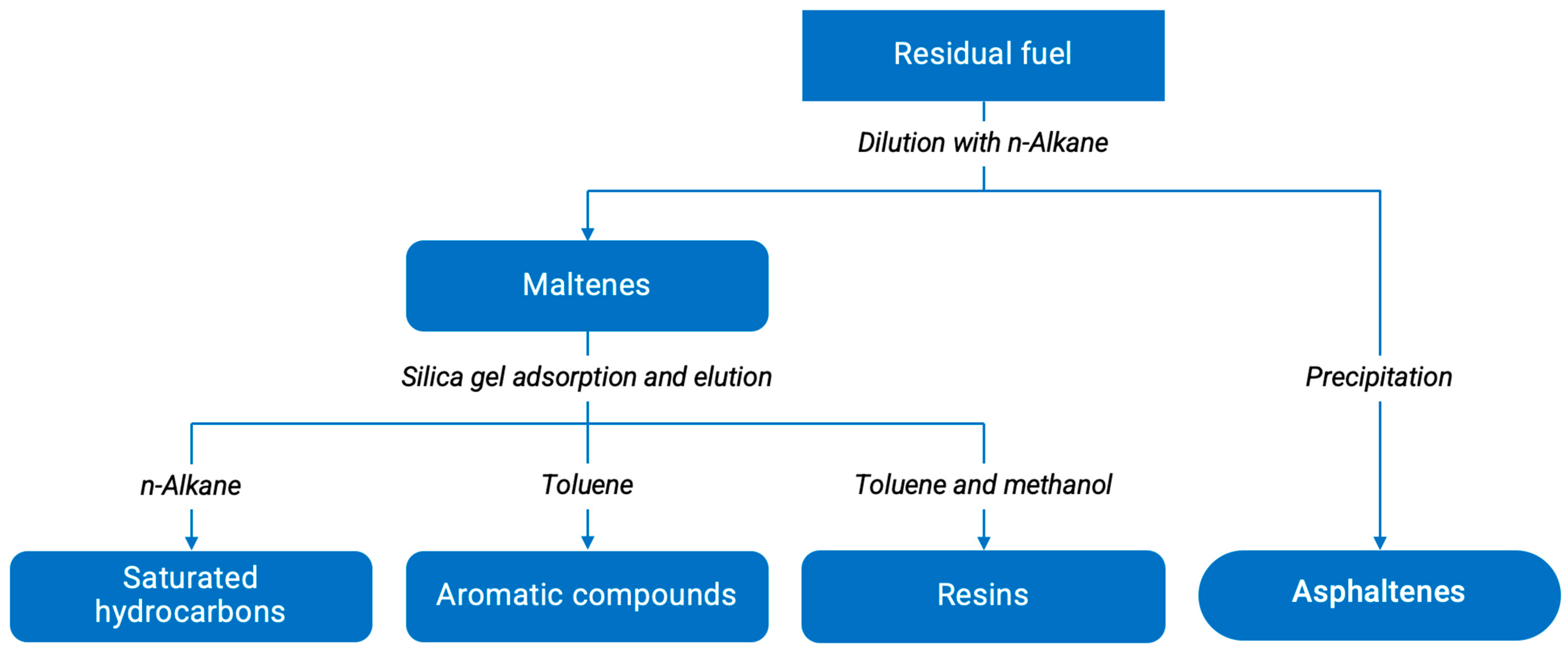
2.2. Hydrocarbon Fuels SARA and GCMS
2.3. Sludge Elemental Analysis
2.4. Sludge XRD-Analysis
2.5. Sludge FT-IR-Analysis
2.6. Sludge SEM
2.7. Modified TSP Analysis
3. Results and Discussion
3.1. Deasphaltisate Study as VLSFO
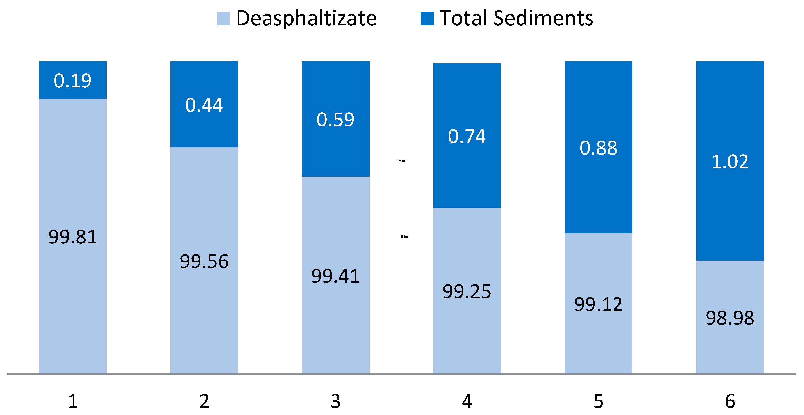
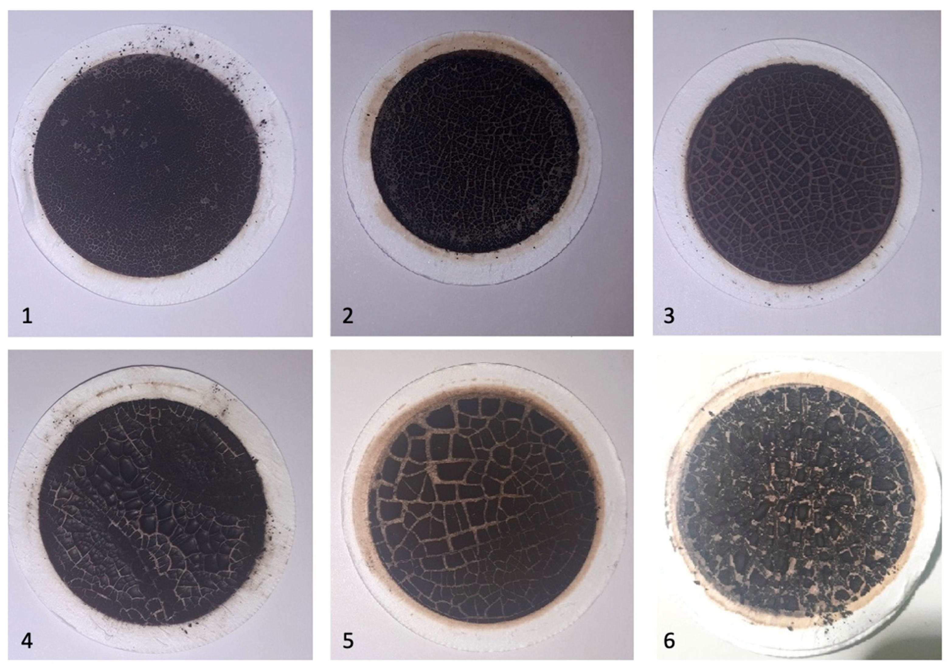
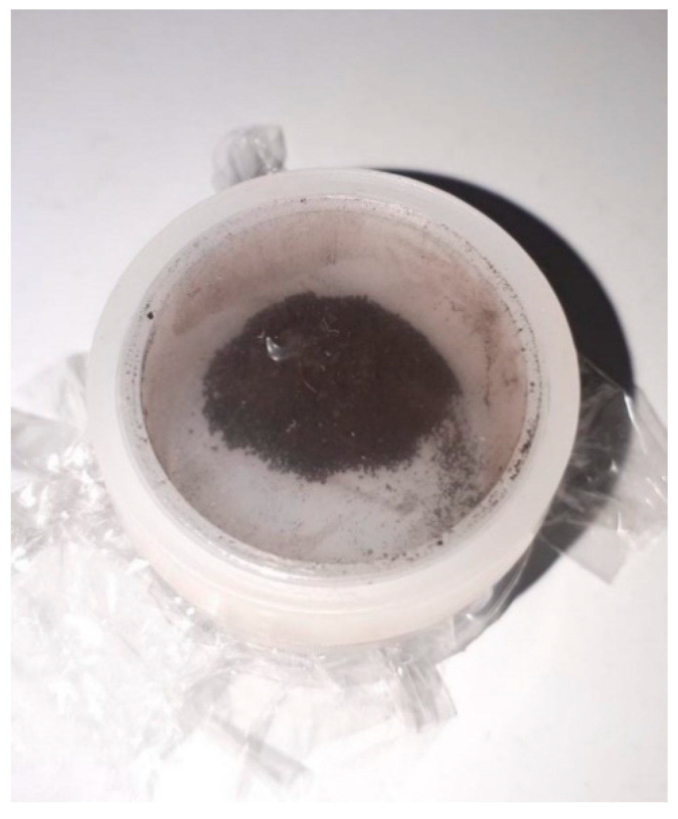
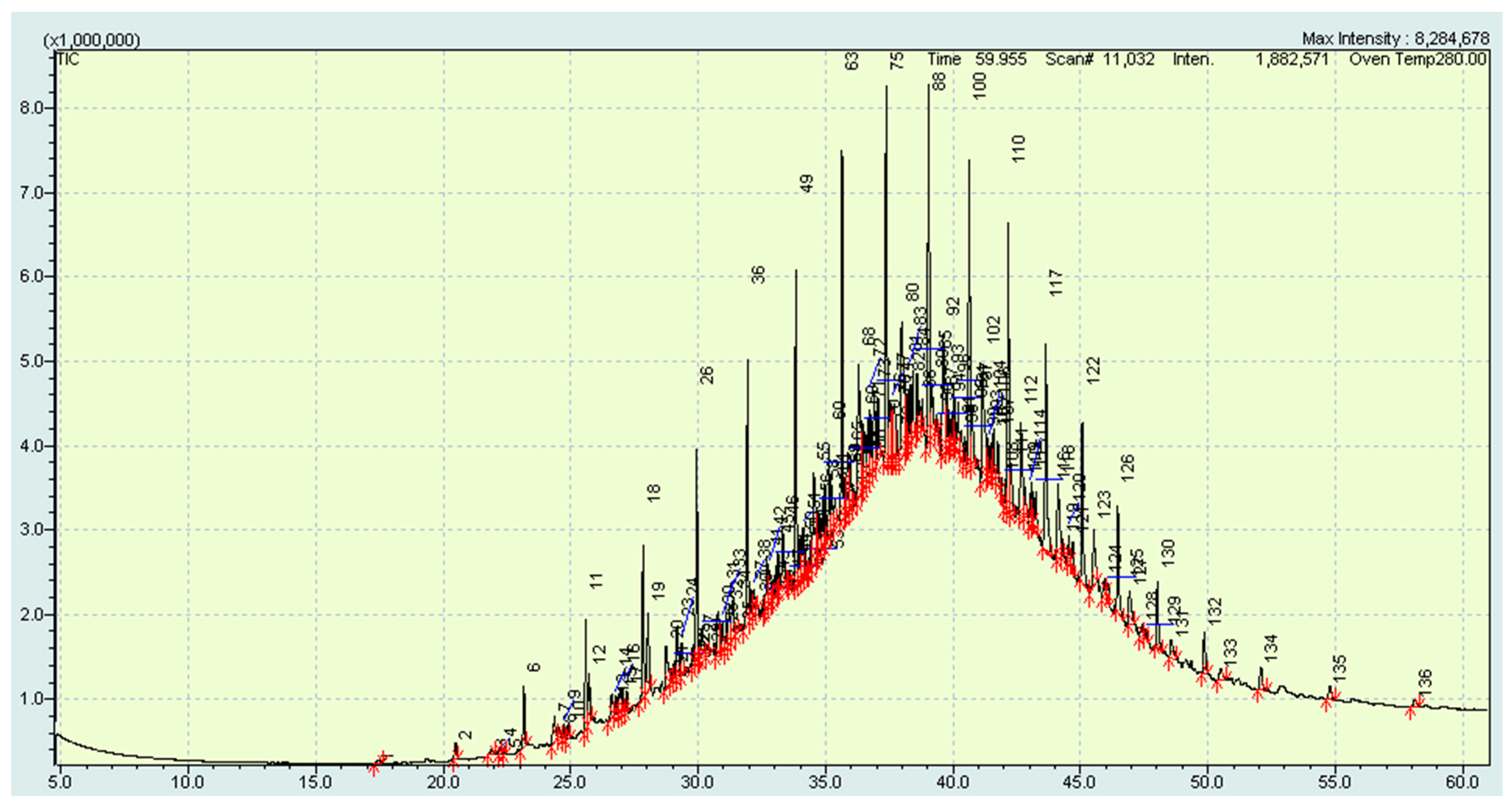
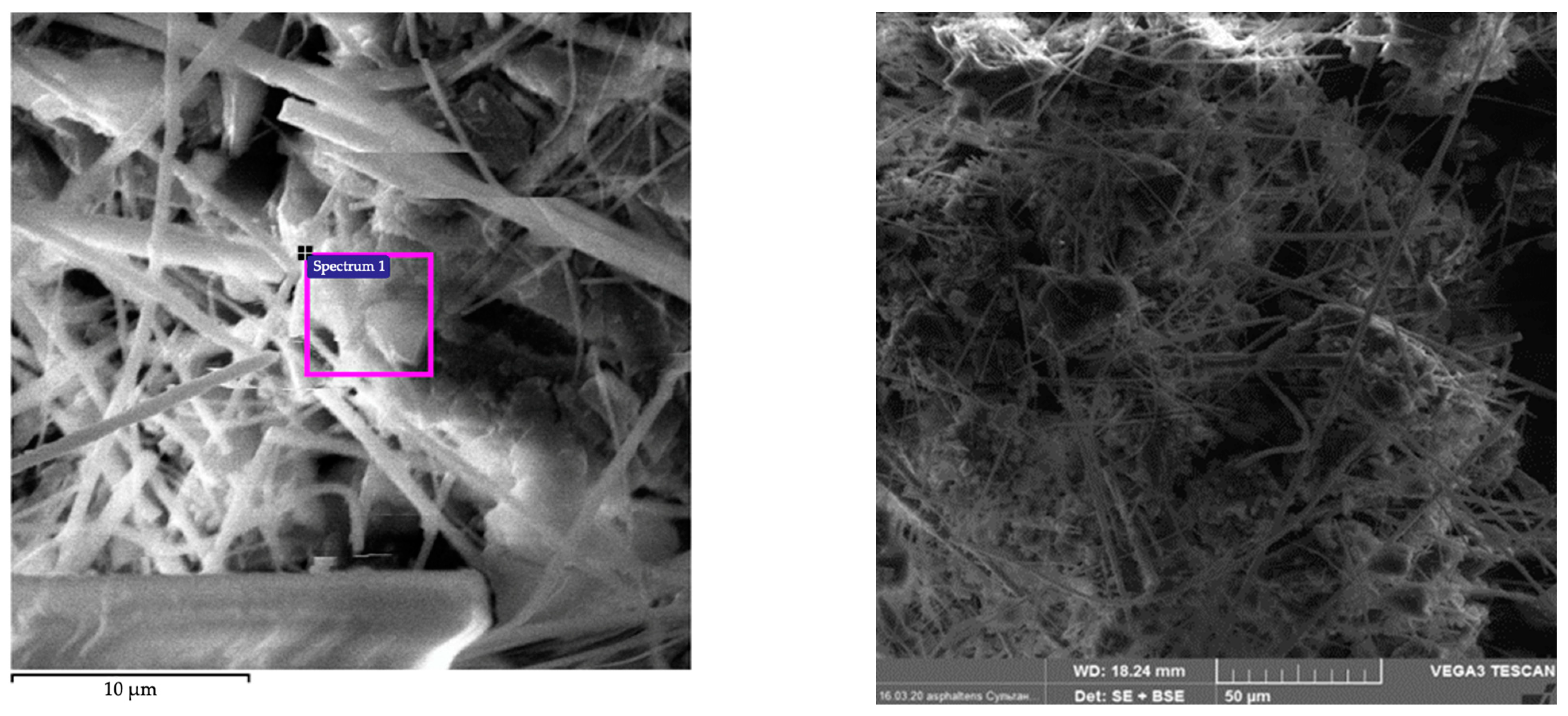
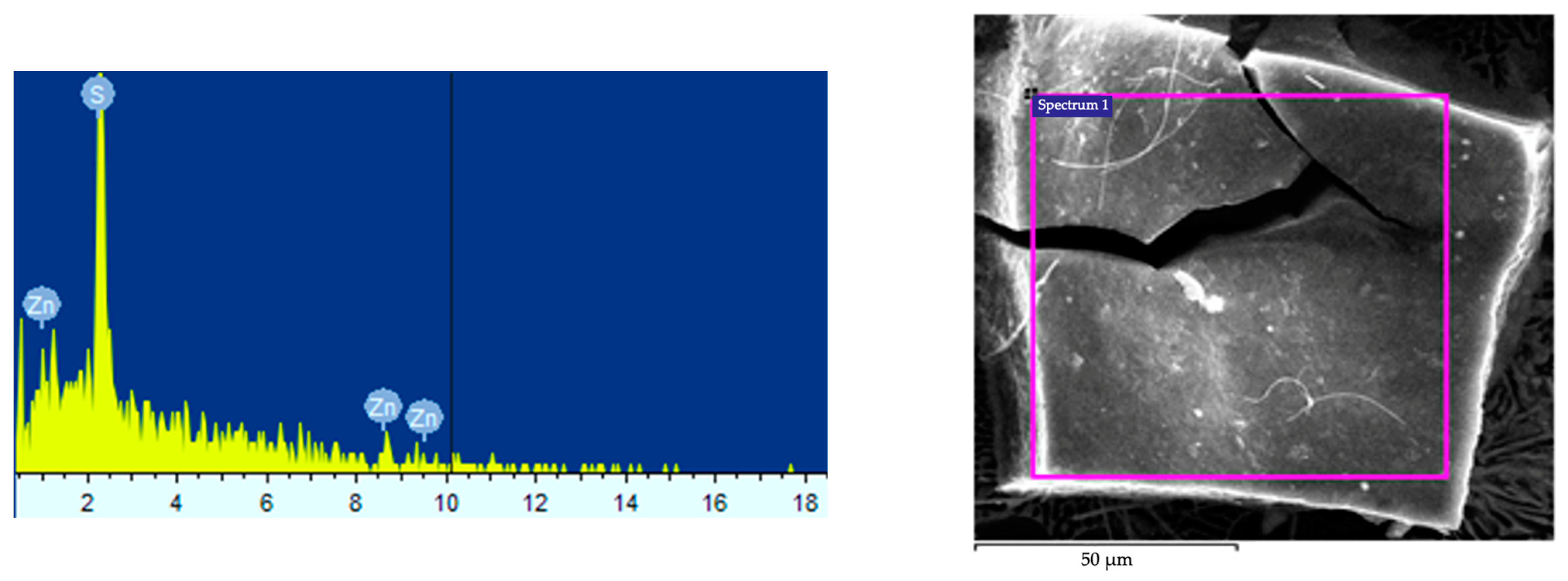
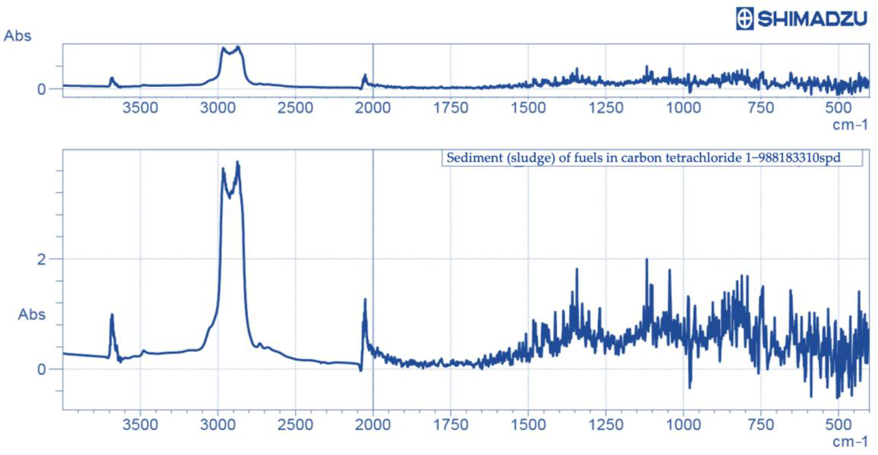
3.2. Deasphaltisation Sediment (Sludge) Investigation
4. Conclusions
5. Patents
Author Contributions
Funding
Institutional Review Board Statement
Informed Consent Statement
Data Availability Statement
Acknowledgments
Conflicts of Interest
Abbreviations
| GOST | Russian government standard |
| EGC | Exhaust gas cleaning |
| HSFO | High-sulphur fuel oil |
| IMO | International Maritime Organisation |
| ISO | International organization for standardization |
| LNG | Liquefied natural gas |
| SARA | Saturate, aromatic, resin, and asphaltene |
| TSA | Total sediment accelerated |
| TSP | Total sediment potential |
| VLSFO | Very low sulphur fuel oil |
References
- Vedachalam, S.; Baquerizo, N.; Dalai, A.K. Review on impacts of low sulfur regulations on marine fuels and compliance options. Fuel 2022, 310, 122243. [Google Scholar] [CrossRef]
- Ju, H.-j.; Jeon, S.-k. Analysis of Characteristic Changes of Blended Very Low Sulfur Fuel Oil on Ultrasonic Frequency for Marine Fuel. J. Mar. Sci. Eng. 2022, 10, 1254. [Google Scholar] [CrossRef]
- Lavrik, A.; Zhukovskiy, Y.; Buldysko, A. Features of the Optimal Composition Determination of Energy Sources During Multi-Criterial Search in the Russian Arctic Conditions. In Proceedings of the International Youth Conference on Radio Electronics, Electrical and Power Engineering, Moscow, Russia, 12–14 March 2020; p. 9059215. [Google Scholar] [CrossRef]
- Buslaev, G.; Tsvetkov, P.; Lavrik, A.; Kunshin, A.; Loseva, E.; Sidorov, D. Ensuring the Sustainability of Arctic Industrial Facilities under Conditions of Global Climate Change. Resources 2021, 10, 128. [Google Scholar] [CrossRef]
- Bolshunov, A.V.; Vasilev, D.A.; Ignatiev, S.A.; Dmitriev, A.N.; Vasilev, N.I. Mechanical drilling of glaciers with bottom-hole scavenging with compressed air. Ice Snow 2022, 62, 35–46. [Google Scholar] [CrossRef]
- Turkeev, A.; Vasilev, N.; Lipenkov, V.; Bolshunov, A.; Ekaykin, A.; Dmitriev, A.; Vasilev, D. Drilling the new 5G-5 branch hole at Vostok Station for collecting a replicate core of old meteoric ice. Ann. Glaciol. 2021, 62, 305–310. [Google Scholar] [CrossRef]
- Gendler, S.; Prokhorova, E. Risk-based methodology for determining priority directions for improving occupational safety in the mining industry of the Arctic zone. Resources 2021, 10, 20. [Google Scholar] [CrossRef]
- Nigmetov, R.; Nurahmedova, A.; Popadin, N. On the upgrading of high-sulfur fuel oil of the Astrakhan gas condensate. Bull. Astrakhan State Tech. Univ. 2017, 1, 32–36. [Google Scholar]
- Gaile, A.; Kostenko, A.; Zalischevskii, G.; Semenov, L.; Kaifadzhyan, E. Increasing the quality of furnace residual fuel oils. Extraction treatment with n-methylpyrrolidone. Chem. Technol. Fuels Oils 2005, 41, 249–259. [Google Scholar] [CrossRef]
- Mardashov, D.V.; Bondarenko, A.V.; Raupov, I.R. Design procedure of technological parameters of non-Newtonian fluids injection into an oil well during workover operation. J. Min. Inst. 2022, Online First, 1–14. [Google Scholar]
- Abdellatief, T.M.M.; Ershov, M.A.; Kapustin, V.M.; Ali Abdelkareem, M.; Kamil, M.; Olabi, A.G. Recent trends for introducing promising fuel components to enhance the anti-knock quality of gasoline: A systematic review. Fuel 2021, 291, 120112. [Google Scholar] [CrossRef]
- Smyshlyaeva, K.I.; Rudko, V.A.; Povarov, V.G.; Shaidulina, A.A.; Efimov, I.; Gabdulkhakov, R.R.; Pyagay, I.N.; Speight, J.G. Influence of Asphaltenes on the Low-Sulphur Residual Marine Fuels’ Stability. J. Mar. Sci. Eng. 2021, 9, 1235. [Google Scholar] [CrossRef]
- Vráblík, A.; Hidalgo-Herrador, J.M.; Černý, R. RGB histograms as a reliable tool for the evaluation of fuel oils stability. Fuel 2018, 216, 16–22. [Google Scholar] [CrossRef]
- Povarov, V.G.; Efimov, I.; Smyshlyaeva, K.I.; Rudko, V.A. Application of the UNIFAC Model for the Low-Sulfur Residue Marine Fuel Asphaltenes Solubility Calculation. J. Mar. Sci. Eng. 2022, 10, 1017. [Google Scholar] [CrossRef]
- Vráblík, A.; Schlehöfer, D.; Dlasková Jaklová, K.; Hidalgo Herrador, J.M.; Černý, R. Comparative Study of Light Cycle Oil and Naphthalene as an Adequate Additive to Improve the Stability of Marine Fuels. ACS Omega 2022, 7, 2127–2136. [Google Scholar] [CrossRef] [PubMed]
- Zhou, J.; Zhou, S.; Zhu, Y. Characterization of Particle and Gaseous Emissions from Marine Diesel En-gines with Different Fuels and Impact of After-Treatment Technology. Energies 2017, 10, 1110. [Google Scholar] [CrossRef]
- Ershov, M.A.; Savelenko, V.D.; Makhova, U.A.; Kapustin, V.M.; Abdellatief, T.M.M.; Karpov, N.V.; Dutlov, E.V.; Borisanov, D.V. Perspective towards a gasoline-property-first approach exhibiting octane hyperboosting based on isoolefinic hydrocarbons. Fuel 2022, 321, 124016. [Google Scholar] [CrossRef]
- Sverchkov, I.; Chukaeva, M.; Matveeva, V. Influence of preparation and combustion parameters of coal-water slurries on gas emission chemistry. Environ. Sci. Pollut. Res. 2022, 29, 44042–44053. [Google Scholar] [CrossRef]
- Corbett, J.J.; Winebrake, J.J. Emissions Tradeoffs among Alternative Marine Fuels: Total Fuel Cycle Analysis of Residual Oil, Marine Gas Oil, and Marine Diesel Oil. J. Air Waste Manage. Assoc. 2008, 58, 538–542. [Google Scholar] [CrossRef]
- Pashkevich, M.; Bykova, M. Methodology for thermal desorption treatment of local soil pollution by oil products at the facilities of the mineral resource industry. J. Min. Inst. 2022, 253, 49–60. [Google Scholar] [CrossRef]
- Gulyaeva, L.; Khavkin, V.; Shmelkova, O.; Vinogradova, N.; Bitiev, G.; Krasilnikova, L.; Yusovskii, A.; Nikulshin, P. Obtaining low-sulphur high-viscosity marine fuel by hydroprocessing of oil residues. Chem. Technol. Fuels Oils 2018, 6, 3–6. [Google Scholar]
- Bolobov, V.; Popov, G. Methodology for testing pipeline steels for resistance to grooving corrosion. J. Min. Inst. 2021, 252, 854–860. [Google Scholar] [CrossRef]
- Wu, P.-C.; Lin, C.-Y. Strategies for the Low Sulfur Policy of IMO—An Example of a Container Vessel Sailing through a European Route. J. Mar. Sci. Eng. 2021, 9, 1383. [Google Scholar] [CrossRef]
- Litvinenko, V. The Role of Hydrocarbons in the Global Energy Agenda: The Focus on Liquefied Natural Gas. Resources 2020, 9, 59. [Google Scholar] [CrossRef]
- Morenov, V.A.; Leusheva, E.L.; Buslaev, G.V.; Gudmestad, O.T. System of Comprehensive Energy-Efficient Utilization of Associated Petroleum Gas with Reduced Carbon Footprint in the Field Conditions. Energies 2020, 13, 4921. [Google Scholar] [CrossRef]
- Fetisov, V.; Tcvetkov, P.; Müller, J. Tariff approach to regulation of the European gas transportation system: Case of Nord Stream. Energy Rep. 2021, 7, 413–425. [Google Scholar] [CrossRef]
- Park, J.; Choi, I.; Oh, J.; Lee, C. Nitrogen Oxides and Particulate Matter from Marine Diesel Oil (MDO), Emulsified MDO, and Dimethyl Ether Fuels in Auxiliary Marine Engines. J. Mar. Sci. Eng. 2020, 8, 322. [Google Scholar] [CrossRef]
- Lee, T.-H.; Lee, S.-H.; Lee, J.-K. Exhaust Gas Emission Improvements of Water/Bunker C Oil-Emulsified Fuel Applied to Marine Boiler. J. Mar. Sci. Eng. 2021, 9, 477. [Google Scholar] [CrossRef]
- Yankovsky, S.; Tolokol’nikov, A.; Gorshkov, A.; Misyukova, A.; Kuznetsov, G. Justification of the Re-duction Possibility of Sulfur Oxides and Fly Ash Emissions during Co-Combustion of Coal and Waste from Woodworking Enterprises. Appl. Sci. 2021, 11, 11719. [Google Scholar] [CrossRef]
- Palyanitsina, A.; Safiullina, E.; Byazrov, R.; Podoprigora, D.; Alekseenko, A. Environmentally Safe Technology to Increase Efficiency of High-Viscosity Oil Production for the Objects with Advanced Water Cut. Energies 2022, 15, 753. [Google Scholar] [CrossRef]
- Rizzo, A.M.; Chiaramonti, D. Blending of Hydrothermal Liquefaction Biocrude with Residual Marine Fuel: An Experimental Assessment. Energies 2022, 15, 450. [Google Scholar] [CrossRef]
- Berdugo Vilches, T.; Maric, J.; Thunman, H.; Seemann, M. Mapping the Effects of Potassium on Fuel Conversion in Industrial-Scale Fluidized Bed Gasifiers and Combustors. Catalysts 2021, 11, 1380. [Google Scholar] [CrossRef]
- Ramirez, J.; Brown, R.; Rainey, T. A Review of Hydrothermal Liquefaction Bio-Crude Properties and Prospects for Upgrading to Transportation Fuels. Energies 2015, 8, 6765–6794. [Google Scholar] [CrossRef]
- Gulyaeva, L.A.; Lobashova, M.M.; Mitusova, T.N.; Shmel’kova, O.I.; Khavkin, V.A.; Nikul’shin, P.A. Production of Low-Sulfur Marine Fuel. Chem. Technol. Fuels Oils 2020, 55, 704–711. [Google Scholar] [CrossRef]
- Beloglazov, I.; Morenov, V.; Leusheva, E.; Gudmestad, O.T. Modeling of Heavy-Oil Flow with Regard to Their Rheological Properties. Energies 2021, 14, 359. [Google Scholar] [CrossRef]
- Nurgalieva, K.S.; Saychenko, L.A.; Riazi, M. Improving the Efficiency of Oil and Gas Wells Complicated by the Formation of Asphalt–Resin–Paraffin Deposits. Energies 2021, 14, 6673. [Google Scholar] [CrossRef]
- Raupov, I.R.; Burkhanov, R.N.; Lutfullin, A.A.; Maksyutin, A.V.; Lebedev, A.B.; Safiullina, E.U. Experience in the Application of Hydrocarbon Optical Studies in Oil Field Development. Energies 2022, 15, 3626. [Google Scholar] [CrossRef]
- Zvereva, E.R.; Makarova, A.O.; Bakhtiyarova, Y.V.; Korolev, V.I.; Ilyin, N.P.; Turanov, A.N.; Zueva, O.S. Reuse of low sulfur oil residues as a base for boiler and marine fuel. Power Eng. Res. Equip. Technol. 2022, 24, 16–28. [Google Scholar] [CrossRef]
- Ancheyta, J. Hydro-imp technology for heavy oil refining. J. Min. Inst. 2017, 224, 229–234. [Google Scholar] [CrossRef]
- Speight, J.G. Petroleum asphaltenes—Part 2: The effect of asphaltenes and resin constituents on recovery and refining processes. Oil Gas Sci. Technol. 2004, 59, 479–488. [Google Scholar] [CrossRef]
- Kudinova, A.A.; Poltoratckaya, M.E.; Gabdulkhakov, R.R.; Litvinova, T.E.; Rudko, V.A. Parameters influence establishment of the petroleum coke genesis on the structure and properties of a highly porous carbon material obtained by activation of KOH. J. Porous Mater. 2022, 29, 1599–1616. [Google Scholar] [CrossRef]
- Buslaev, G.; Morenov, V.; Konyaev, Y.; Kraslawski, A. Reduction of carbon footprint of the production and field transport of high-viscosity oils in the Arctic region. Chem. Eng. Process. Process Intensif. 2020, 108189, 1–8. [Google Scholar] [CrossRef]
- Smyshlyaeva, K.I.; Rudko, V.A.; Kuzmin, K.A.; Povarov, V.G. Asphaltene genesis influence on the low-sulfur residual marine fuel sedimentation stability. Fuel 2022, 328, 125291. [Google Scholar] [CrossRef]
- Gaile, A.A.; Vereshchagin, A.V.; Klement’ev, V.N. Refining of Diesel and Ship Fuels by Extraction and Combined Methods. Part 1. Use of Ionic Liquids as Extractants. Russ. J. Appl. Chem. 2019, 92, 453–475. [Google Scholar] [CrossRef]
- Gaile, A.A.; Vereshchagin, A.V.; Klement’ev, V.N. Refining of Diesel and Ship Fuels by Extraction and Combined Methods. Part 2. Use of Organic Solvents as Extractants. Russ. J. Appl. Chem. 2019, 92, 583–595. [Google Scholar] [CrossRef]
- Sánchez, R.; Lefevre, J.; Todolí, J.-L. Direct elemental analysis of petroleum heavy fractions by means of ICP-OES equipped with a high temperature torch integrated sample introduction system. J. Anal. At. Spectrom. 2019, 34, 664–673. [Google Scholar] [CrossRef]
- Carter, S.; Clough, R.; Fisher, A.; Gibson, B.; Russell, B.; Waack, J. Atomic spectrometry update: Review of advances in the analysis of metals, chemicals and materials. J. Anal. At. Spectrom. 2019, 34, 2159–2216. [Google Scholar] [CrossRef]
- Popova, A.N.; Sukhomlinov, V.S.; Mustafaev, A.S. Accounting for Interelement Interferences in Atomic Emission Spectroscopy: A Nonlinear Theory. Appl. Sci. 2021, 11, 11237. [Google Scholar] [CrossRef]
- Chukaeva, M.; Matveeva, V.; Sverchkov, I. Complex processing of high-carbon ash and slag waste. J. Min. Inst. 2022, 253, 97–104. [Google Scholar] [CrossRef]
- Makarov, I.S.; Golova, L.K.; Mironova, M.V.; Vinogradov, M.I.; Bermeshev, M.V.; Berkovich, A.K.; Kulichikhin, V.G. Structural and Morphological Features of Carbon—Silicon-Carbide Fibers Based on Cellulose and Triethoxyvinylsilane. Fibre Chem. 2018, 50, 79–84. [Google Scholar] [CrossRef]
- Savchenkov, S.A. The research of obtaining master alloys magnesium-gadolinium process by the method of metallothermic recovery. Tsvetnye Met. 2019, 5, 33–39. [Google Scholar] [CrossRef]
- Gabdulkhakov, R.R.; Rudko, V.A.; Pyagay, I.N. Methods for modifying needle coke raw materials by introducing additives of various origin (review). Fuel 2022, 310, 122265. [Google Scholar] [CrossRef]
- Savchenkov, S.; Beloglazov, I. Features of the Process Obtaining of Mg-Zn-Y Master Alloy by the Metallothermic Recovery Method of Yttrium Fluoride Melt. Crystals 2022, 12, 771. [Google Scholar] [CrossRef]
- Vasilyeva, N.V.; Boikov, A.V.; Erokhina, O.O.; Trifonov, A.Y. Automated digitization of radial charts. J. Min. Inst. 2021, 247, 82–87. [Google Scholar] [CrossRef]
- Boikov, A.; Payor, V.; Savelev, R.; Kolesnikov, A. Synthetic Data Generation for Steel Defect Detection and Classification Using Deep Learning. Symmetry 2021, 13, 1176. [Google Scholar] [CrossRef]
- Chukaeva, M.; Zaytseva, T.; Matveeva, V.; Sverchkov, I. Purification of Oil-Contaminated Wastewater with a Modified Natural Adsorbent. Ecol. Eng. Environ. Technol. 2021, 22, 46–51. [Google Scholar] [CrossRef]


| No. | Indicator Name | Unit of Measurement | Regulation of the Test Method | Samples | ||||
|---|---|---|---|---|---|---|---|---|
| No.1 | No.2 | No.3 | No.4 | No.5 | ||||
| 1 | Density at 15 °C | kg/m3 | ISO 12185 | 833.5 | 956.0 | 973.6 | 983.6 | 1005.8 |
| 2 | Kinematic viscosity at 50 °C | mm2/s | GOST 33 ISO 3104 | 12.1 | 321.5 | 633.4 | 530.4 | 416.7 |
| 3 | Flashpoint PMCC | °C | GOST R EN ISO 2719 | 181.0 | 98.0 | 112.0 | 124.0 | 119.0 |
| 4 | Sulphur mass fraction | % | GOST R 51947 ISO 8754 | 0.004 | 1.276 | 2.530 | 2.851 | 3.15 |
| 5 | Pour point | °C | ASTM D 6749 | 26.0 | 16.0 | 19.0 | 21.0 | 23.0 |
| 6 | Mass fraction of water | % | GOST R 51946 ISO 3733 | – | 0.05 | 0.1 | 0.1 | 0.1 |
| 7 | Total sediment potential | % | GOST 33360 ISO 10307-2 | 0.01 | 0.02 | 0.02 | 0.03 | 0.03 |
| No. | Fuel Mixture Components | Mixing Ratio, % | Blends | ||
|---|---|---|---|---|---|
| Kinematic Viscosity at 50 °C, mm2/s | Density at 15 °C, kg/m3 | Sulphur Mass Fraction, % | |||
| 1 | Samples No.1 and 2 | 49.6:50.4 | 41.50 | 892.1 | 0.600 |
| 2 | Samples No.1 and 3 | 65.0:35.0 | 29.91 | 877.7 | 0.801 |
| 3 | Samples No.1, 3 and 4 | 60.0:11.0:29.0 | 33.94 | 886.8 | 1.001 |
| 4 | Samples No.1, 3 and 4 | 50.0:40.0:10.0 | 48.95 | 899.0 | 1.197 |
| 5 | Samples No.1 and 5 | 51.0:49.0 | 41.36 | 909.9 | 1.399 |
| 6 | Samples No.1 and 5 | 44.6:55.4 | 51.28 | 920.9 | 1.600 |
| No. | Indicator Name | Unit of Measurement | Regulation of the Test Method | Blends | |||||
|---|---|---|---|---|---|---|---|---|---|
| No.1 | No.2 | No.3 | No.4 | No.5 | No.6 | ||||
| 1 | Density at 15 °C | kg/m3 | ISO 12185 | 892.3 | 877.5 | 887.2 | 898.4 | 910.3 | 921.6 |
| 2 | Kinematic viscosity at 50 °C | mm2/s | GOST 33 ISO 3104 | 42.08 | 29.77 | 34.24 | 47.16 | 42.40 | 53.81 |
| 3 | Sulphur mass fraction | % | GOST R 51947 ISO 8754 | 0.603 | 0.799 | 1.008 | 1.180 | 1.405 | 1.62 |
| 4 | Pour point | °C | ASTM D 6749 | 21.0 | 24.0 | 23.0 | 22.0 | 24.0 | 25.0 |
| 5 | Total sediment potential | % | GOST 33360 ISO 10307-2 | 0.17 | 0.41 | 0.56 | 0.70 | 0.84 | 0.98 |
| No. | Indicator Name | Unit of Measurement | Blends | |||||
|---|---|---|---|---|---|---|---|---|
| No.1 | No.2 | No.3 | No.4 | No.5 | No.6 | |||
| Fuel composition | ||||||||
| 1 | Density at 15 °C | kg/m3 | 891.6 | 875.8 | 885.4 | 896.2 | 907.3 | 918.8 |
| 2 | Kinematic viscosity at 50 °C | mm2/s | 41.68 | 29.35 | 33.44 | 45.91 | 41.45 | 51.19 |
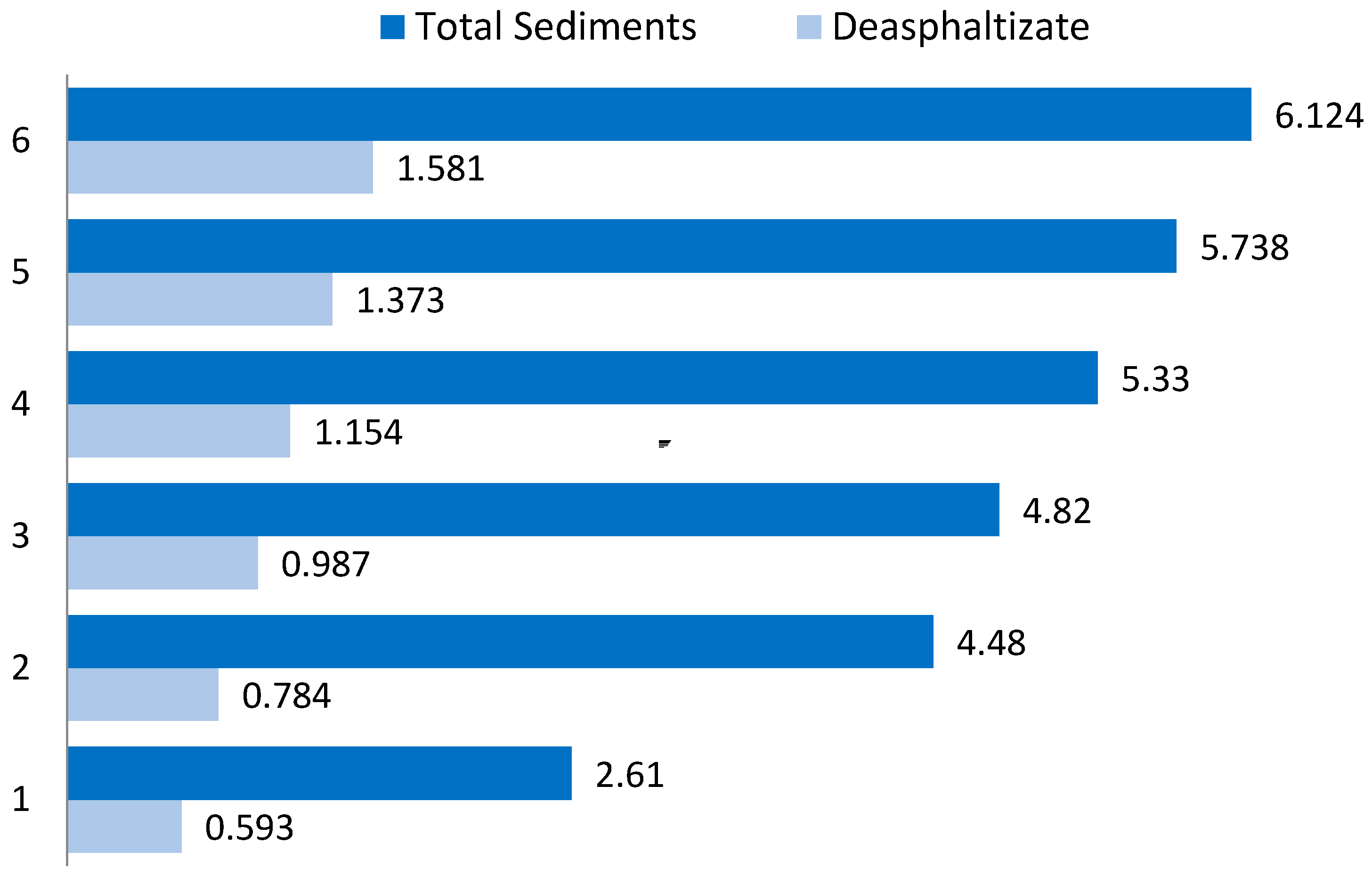
| 3 | Sulphur mass fraction | % | 0.593 | 0.784 | 0.987 | 1.154 | 1.373 | 1.581 |
| 4 | Pour point | °C | 21.0 | 24.0 | 22.0 | 21.0 | 22.0 | 23.0 |
| Sediment or sludge (after filtration) | ||||||||
| 5 | Sulphur mass fraction | % | 2.61 | 4.48 | 4.82 | 5.33 | 5.74 | 6.12 |
| Fuel Samples | Asphaltenes | N-paraffins | Iso-paraffins | Naphthenes | Alkenes | Aromatic Hydrocarbons | Resins |
|---|---|---|---|---|---|---|---|
| No.1 | – | 71.93 | 18.35 | 2.62 | 5.55 | 1.55 | – |
| No.2 | 2.53 | 54.14 | 22.74 | 5.43 | 0.57 | 14.12 | 0.47 |
| Group Composition | Content, % |
|---|---|
| N-paraffins | 39.01 |
| Aromatic hydrocarbons | 15.63 |
| Iso-paraffins | 15.29 |
| Naphthenes | 3.01 |
| Unidentified | 28.16 |
| Composition | Content, % |
|---|---|
| Carbon | 84.936 |
| Hydrogen | 10.709 |
| Nitrogen | 0.639 |
| Sulphur | 2.610 |
| Oxygen | 1.076 |
| Ash content | 0.03 |
| Parameter | Value |
|---|---|
| Reflex (002) | |
| 2θ, ° | 24.9800 |
| Half-width, ° | 2.8400 |
| d002, Å | 3.5618 |
| Lc, Å | 27.7648 |
| Reflex (110) | |
| 2θ, ° | 77.5000 |
| Half-width, ° | 0.6000 |
| d110, Å | 1.2307 |
| La, Å | 174.0710 |
Publisher’s Note: MDPI stays neutral with regard to jurisdictional claims in published maps and institutional affiliations. |
© 2022 by the authors. Licensee MDPI, Basel, Switzerland. This article is an open access article distributed under the terms and conditions of the Creative Commons Attribution (CC BY) license (https://creativecommons.org/licenses/by/4.0/).
Share and Cite
Sultanbekov, R.; Denisov, K.; Zhurkevich, A.; Islamov, S. Reduction of Sulphur in Marine Residual Fuels by Deasphalting to Produce VLSFO. J. Mar. Sci. Eng. 2022, 10, 1765. https://doi.org/10.3390/jmse10111765
Sultanbekov R, Denisov K, Zhurkevich A, Islamov S. Reduction of Sulphur in Marine Residual Fuels by Deasphalting to Produce VLSFO. Journal of Marine Science and Engineering. 2022; 10(11):1765. https://doi.org/10.3390/jmse10111765
Chicago/Turabian StyleSultanbekov, Radel, Kirill Denisov, Aleksei Zhurkevich, and Shamil Islamov. 2022. "Reduction of Sulphur in Marine Residual Fuels by Deasphalting to Produce VLSFO" Journal of Marine Science and Engineering 10, no. 11: 1765. https://doi.org/10.3390/jmse10111765
APA StyleSultanbekov, R., Denisov, K., Zhurkevich, A., & Islamov, S. (2022). Reduction of Sulphur in Marine Residual Fuels by Deasphalting to Produce VLSFO. Journal of Marine Science and Engineering, 10(11), 1765. https://doi.org/10.3390/jmse10111765