Abstract
Bionic underwater robots have many advantages such as high mobility, high efficiency, high affinity, etc. They are especially suitable for tasks such as collecting hydrographic information and for detailed surveys of the marine environment. These tasks are based on their high-precision attitude control. Therefore, this paper proposes a control scheme for a bionic underwater robot—a manta robot. To improve the depth retention capability of the manta robot, a S-plane controller based on asymmetric output was designed in combination with the longitudinal motion characteristics of the manta robot. In addition, to achieve good motion control for the manta robot under conditions of large changes in the heading angle, the fuzzy controller and the heading transition target value function were combined to design the heading controller of the manta robot. Finally, the feasibility and reliability of the control system of the manta robot were verified by pool experiments. The experimental results showed that the depth control error was within cm and the heading control error was within degrees. The control scheme proposed in this paper achieves high-precision attitude control of the manta robot, providing a basis for the practical application of the manta robot.
1. Introduction
With the increasing demand for ocean exploration and intervention tasks, several underwater vehicles have been developed for use in various areas of ocean exploration and exploitation [1]. As an important tool for exploring and monitoring the ocean, research on unmanned autonomous underwater vehicles (AUVs) has been very productive [2,3,4,5,6,7,8]. AUVs have been widely used for underwater operations in numerous fields such as marine environmental monitoring and resource exploration [9,10,11], offshore oil and gas resource exploration [12,13], submarine pipeline monitoring [14,15], and submarine investigation [16]. At present, the rotary AUV with propeller propulsion is still the most used underwater vehicle, but with the increasing complexity and diversity of underwater operational requirements, bionic underwater vehicles are receiving increasing attention [17]. Compared with traditional underwater vehicles that are propelled by propellers, this type of bionic underwater vehicle has many compelling advantages, including stronger resistance to interference, higher propulsion efficiency, better maneuverability, and less operational noise [18,19]. Bionic underwater vehicles can be divided into two main types according to their different propulsion methods: body and/or caudal Fin (BCF) mode, and median and/or paired fin (MPF) mode [20]. The bionic underwater vehicle with MPF propulsion mode has a small turning radius and good navigational stability. In particular, due to its unique shape and structure, it has a strong carrying capacity, which makes it especially suitable as an underwater operation carrying platform, carrying different types of sensors to achieve a variety of operational tasks [21,22,23,24,25,26].
Researchers have studied the bionic underwater vehicle in terms of both the prototype structure and prototype control, and work on developing the prototype structure has achieved some relatively good results [27,28,29,30,31,32,33,34,35,36]. The control performance of the bionic underwater vehicle is an important factor in determining its mission execution capability. Among the many control objectives, depth control in the longitudinal plane and heading control in the horizontal plane are vital to all missions. Therefore, depth control and heading control are two important basic control objectives of bionic underwater vehicle control. To achieve the simple task of a robot fish cruising at the desired depth in the water, Zhong et al. implemented a depth controller for a robot fish based on fuzzy control [37]. Cao et al. used the Takagi–Sugeno (T–S) fuzzy control method to achieve depth control of the robotic manta and experimentally verified the effectiveness and accuracy of the T–S fuzzy neural network controller for this robotic manta [38]. Wei et al. designed a depth controller based on the active disturbance rejection control (ADRC) technique to achieve the depth control of a new bionic underwater robot based on a squid proto-type. Both the simulation and experimental results showed that the depth controller, which was designed based on the active disturbance rejection control technique outperformed the proportional integral derivative (PID) controller [39]. Yu et al. proposed a hybrid controller that combined sliding mode control and fuzzy control to achieve depth control for bionic dolphins [40]. For the control of the horizontal motion of a bionic robot fish, Wang et al. [34] were inspired by cuttlefish and designed a bionic underwater vehicle with two undulatory fins. To realize the heading control of the designed underwater bionic vehicle, they proposed a hybrid heading control method combining the disturbance rejection control (ADRC) and fuzzy strategy, and the effectiveness of the control system was verified by experiments. Yan et al. proposed a CPG-based sliding film controller (SMC-CPG) by combining a central pattern generator (CPG) and a sliding mode controller. The experimental results showed that under the initial error condition, the bionic machine fish could quickly eliminate the position error and heading error under the control of the SMC-CPG controller. With regard to linear trajectory tracking, the heading angle error always fluctuated between −40° and 60°, and the effectiveness of the proposed SMC-CPG controller was verified by experiments [41]. Chen, et al. combined a PID control algorithm and central mode generator to propose a direction-tracking control method based on a bionic closed-loop central pattern generator (CPG) for robot fish, which was experimentally verified in a pool. The experimental results showed that the proposed control strategy worked well and the robot fish effectively completed the direction tracking [42]. Cao et al. utilized a classical T–S fuzzy neural network controller for the heading control of a robot manta, and verified the error of the heading controller in in a pool experiment [43]. Hao et al. were inspired by the biological yaw mode to design the yaw mode based on phase difference and amplitude difference for the manta robot. They combined the phase difference and amplitude difference yaw modes to realize the closed-loop heading control of the manta robot, and the effectiveness of the combined mode was verified through experiments [44].
Since the bionic underwater robot is a strongly nonlinear system, it is difficult to establish an accurate mathematical model for it. This results in various problems in relation to the control of the bionic underwater robot. Based on a review of the existing work on bionic underwater robots, there are other applications or methods that do not require an accurate mathematical model of the control object such as fuzzy control. These methods avoid the establishment of a mathematical model of the bionic underwater robot and are very robust although this also presents problems such as the need for strong reliance on human experience; therefore, the final control effect is influenced by human input. In addition, several researchers have also applied control methods such as disturbance suppression control and sliding mode control to the control of bionic underwater vehicles by building simplified underwater vehicle models. However, the results of these control methods depend on the accuracy of the bionic underwater vehicle models and the control algorithms are relatively complex, which is not conducive to engineering implementation.
Therefore, based on the above discussion, the main contributions of this paper are summarized as follows. In this study, we aimed to design a control algorithm that relies less on human experience and is simple to implement, which has the advantage of facilitating the engineering of the control method and the extension of the method to different prototype bionic underwater vehicles. This paper presents a control strategy for a manta robot. In contrast to previous work, this paper considers the motion characteristics of the bionic manta robot in the controller design and investigates the case of large heading errors, which are common when bionic underwater vehicles perform real-world tasks, and are therefore important for the practical application of bionic underwater vehicles. Specifically, this study involved the following steps. A depth controller for the manta robot was designed based on the S-plane control method, combined with the longitudinal motion characteristics of the manta robot, and a heading controller for the manta robot was designed based on the S-plane by combining fuzzy control and the desired heading transition value function. The control of the designed controller for the manta robot was verified by pool experiments.
The sections of this paper are as follows. Section 2 presents the structural design and control system of the manta robot, Section 3 presents the controller design of the manta robot, Section 4 presents the pool experiments and gives the experimental results, and Section 5 discusses the conclusions of this paper and the prospects for future work.
2. Overview of Manta Robot
2.1. Mechanical Structure
The mechanical structure design of the manta robot is based on a modular design. As shown in Figure 1, the manta robot can be divided into three parts: the main body of the manta robot, the flexible pectoral fin and the flexible tail fin. The body length of the prototype is 60 cm, the wingspan is 90 cm, the thickness of the prototype body is 12 cm, and the overall weight is 8.5 kg. The main body of the manta robot is used to carry sensors, control circuits, batteries, and drive servos. All the drive energy of the manta robot is provided by a 7.4 volt, 1500 mAh DC power supply. There are seven drive servos for the manta robot, six for the pectoral fin servos, and one for the tail fin servo, all of which are driven by PWM waves generated by the main control board. The servos are mounted in a sealed compartment attached to the exterior of the main body, which is intended to extend the working life of the servos. Special attention is paid to the fact that both the tail and pectoral fins are composed of two sub-modules: the flexible silicone skin and the fin rays. In this case, each level of fins and their respective driving servos are directly connected by adapters and driven independently by the corresponding servos, with no influence between the fins at different levels. Due to the flexibility of the fins and the silicone skin, traveling waves providing propulsion can form on the fin surface of the pectoral fins when the fins are in motion.
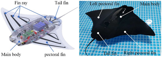
Figure 1.
Model and physical images of the manta robot. The manta robot was configured to be more buoyant than gravity so that the manta robot would float on the water when at rest.
2.2. Control System of the Manta Robot
As shown in Figure 2, the control system of the manta robot consists of the host computer measurement and control system and the control system on board the manta robot. The host computer system is mainly used to send control commands, receive real-time data from the manta robot, and to realize the control and data monitoring of the manta robot. The communication between the host system and the manta robot is done by radio.
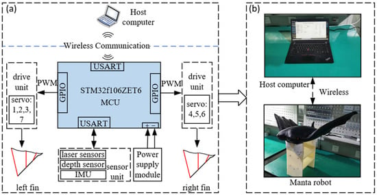
Figure 2.
The control system of the manta robot. (a) Shows the block diagram of the manta robot control system, and (b) shows the physical diagram of the system.
The onboard control system of the manta robot includes the main control unit, actuators, sensors, and so on. The main control unit uses STM32F103ZET6 as the main control chip, which is mainly used to collect and process sensor information and analyze control commands. In addition, the main control unit is also connected to a radio, which realizes the communication between the manta robot and the host computer system. The drive unit consists of servos. The main control unit analyzes the pectoral/caudal fin motion parameters at the current moment according to the control commands in real-time, including the oscillation frequency and amplitude of the fins and the phase difference between the fins at each level, and converts these control commands into pulse width modulation (PWM) waves to drive the servos.
The sensor unit consists of various sensors on board the manta robot; these mainly include laser sensors, a depth sensor, and an inertial measurement sensor. There are four laser sensors installed on the head of the manta robot that are used to measure the distance to the front, left, right and bottom. A depth sensor is mounted on the tail of the manta robot to measure the depth at the current position. The current depth of the manta robot is returned to the main control unit. The inertial measurement sensor that is installed in the main compartment of the manta robot can be used to obtain the navigation attitude of the manta robot, including the current heading angle, pitch angle, roll angle, and other attitude information. This information is used to achieve control of the attitude of the manta robot.
3. Design of S-Plane-Based Controller
The manta robot is a strongly coupled nonlinear system, and it is difficult to establish an accurate motion model. Among various control algorithms for underwater vehicles, the S-plane controller has been widely used in the control of various underwater robots because of its simple structural form and nonlinear characteristics [45]. Considering the complexity of the motion control of the manta robot, the depth controller and heading controller of the manta robot was designed based on the S-plane control algorithm. Moreover, because the longitudinal motion of the manta robot is mainly influenced by the pitch generated by the tail fin deflection, and the horizontal motion is mainly influenced by the yaw moment and propulsion force generated by the pectoral fin, the three-dimensional motion control of the manta robot was decoupled into depth control in the longitudinal plane and heading control in the horizontal plane. The depth controller and heading controller were designed separately. The control system of the manta robot is shown in Figure 3.
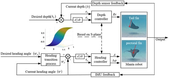
Figure 3.
The motion control system of the manta robot consists of two parts: the depth controller and heading controller. The design of both controllers is based on the S-plane.
3.1. Design of Depth Controller for the Manta Robot
The standard form of the S-plane control algorithm [46] is shown in Equation (1):
where is the normalized deviation, is the normalized deviation rate of change, is the control parameter corresponding to the deviation, is the control parameter corresponding to the deviation rate of change, and is the control output of the controller.
It is also worth noting that the output of the S-plane controller is restricted to the range [–1, 1]. Therefore, when using the S-plane control method for control, the output of the S-plane controller needs to be mapped to the actuator’s execution interval by a gain factor using Equation (2).
where is the gain factor, is the output value of the S-plane, is the mechanical zero of the actuator, and is the actual actuation value of the actuator.
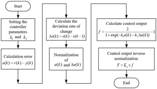
Figure 4.
Flow diagram of standard S-plane control algorithm. The algorithm flow contains a total of 6 steps.

Table 1.
Steps of the flow diagram of standard S-plane control algorithm.
Table 1.
Steps of the flow diagram of standard S-plane control algorithm.
| Steps | Details |
|---|---|
| 1 | Set controller parameters and |
| 2 | Calculate the deviation according to Equation (1). |
| where, is the deviation at the current moment, is the sampled value of the control quantity at the current moment, and is the expected value of the control quantity. | |
| 3 | Since time is discretized in the control system, the deviation rate of change is expressed in a discretized form. The deviation rate of change is calculated according to Equation (1). |
| where, is the deviation rate of change at the current moment, is the deviation at the current moment, and is the deviation at the previous moment. | |
| 4 | Normalization of deviation and deviation rate of change . |
| 5 | Calculate the control output according to Equation (1). |
| Inverse normalization of the control output by Equation (2) | |
Extensive experiments on the manta robot have revealed that its motion in the vertical plane is asymmetric in the upward and downward motion. The upward motion of the manta robot requires more control than the downward motion. This is mainly due to the hydrodynamic shape of the manta robot. Therefore, the classical S-plane is improved by introducing an asymmetric output factor in combination with this motion characteristic. The improved form of the S-plane controller is shown in Equation (5).
where is the normalized deviation, is the normalized deviation rate of change, is the control parameter corresponding to the deviation, is the control parameter corresponding to the deviation rate of change, and is the control output of the controller. and are the factors used to regulate the degree of asymmetry of the S-plane, and both are positive real numbers and .
The adjustment to the depth of the manta robot is achieved by the tail fin deflection; therefore, the output of the S-plane controller is mapped through Equation (6) to the interval of the tail fin deflection angle to obtain the tail fin deflection angle needed for depth adjustment.
where is the tail fin deflection angle, is the control gain, is the output of the controller, and is the tail fin zero position. The basic variation interval of the tail fin bias angle is [−60°, 60°], and the size of this variation interval is determined by the mechanical structure of the manta robot. The zero position of the tail fin is the tail fin offset angle that ensures that the depth of the manta robot is stable and constant. The zero position here is different from the mechanical zero position of the tail fin servo.
3.2. Design of Heading Controller for Manta Robot
When the manta robot performs complex tasks in the horizontal plane, the change in the heading angle will be more frequent compared with the depth, thus the requirements for the controller are higher. Therefore, this paper combines the fuzzy control method and heading transition value function to design a heading controller based on the S-plane control algorithm. The controller structure is shown in Figure 5. Both the amplitude difference and phase difference are used as the control variables of the manta robot [44], The phase mode is suitable for a large heading adjustment with a fast yaw angle speed and small yaw radius. The amplitude mode applies to the adjustment of a small heading, with a slow yaw angle speed and large yaw radius. In this paper, the switching of the two modes is determined by the heading angle error. The motion mode-based S-plane heading controller for the manta robot is shown in Equation (7).
where is the output value of the S-plane controller, is the normalized heading error, is the normalized rate of change of the navigation error, and are the controller parameters in the heading controller that correspond to the normalized navigation error and the normalized rate of change of the heading error, respectively, is the phase difference between the fins of the pectoral fin levels, is the gain factor of the phase difference of the fins, is the amplitude of the pectoral fin, is the gain factor of the amplitude of the pectoral fin, is the current heading angle of the manta robot, is the desired heading angle of the manta robot, and is the heading angle error threshold for switching between the amplitude difference motion mode and the phase difference motion mode.
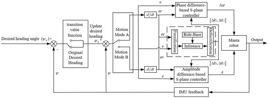
Figure 5.
Block diagram of the course controller. is the final desired heading angle; is the transition heading angle calculated from the heading transition target value function; is the current heading angle measured by the inertial measurement unit (IMU); is the heading angle error; is the rate of change of heading angle error; and are the adjusted control parameters of the S-plane controller; A is the amplitude of the pectoral fin; is the phase difference between the fins of the pectoral fin levels.
3.2.1. Transition Process Based on the Transition Value Function
When the desired heading angle changes abruptly during the navigation process, the control system is equivalent to a step signal being applied. Since the manta robot has large inertia and the actuator has a certain time lag, it is easy to overshoot when the desired heading angle changes significantly in the actual control. Considering the actual situation, the manta robot does not reach the desired heading angle instantaneously, rather, it is a gradual process. Therefore, the idea of task decomposition, as shown in the figure, is adopted for the sudden change in the manta robot’s heading, and several desired heading angles are set as intermediate transition between the current heading angle and the final desired heading angle; thus, the final desired heading angle is approached gradually. The intermediate transition desired heading angles are calculated by the transition target value function of Equation (8).
where is the ith desired heading angle in the heading transition process, is the sign function, is the heading angle error adjustment factor, , is the heading transition factor, is the final desired heading angle, is the heading angle of the manta robot at the beginning of the transition process; n is the number of transitions experienced in the heading transition process.
3.2.2. Fuzzy Inference-Based Parameter Adjustment
In general, the S-plane control algorithm is a simple, efficient, and robust nonlinear control method, which is very suitable for the heading control of an underdriven model-free manta robot; however, the classical S-plane controller does not have the ability to adapt the parameters. Therefore, this paper used the fuzzy control method to realize the online adjustment of the control parameters of the S-plane controller.
The fuzzy controller used to adjust the control parameters of the S-plane controller in this paper is shown in Figure 5. The fuzzy controller contains four components: fuzzification, fuzzy inference, fuzzy rule base, and defuzzification. The actual range of the variation of each variable is referred to as the fundamental domain, where the range of discourse for each variable is determined based on previous experimental evaluations. ranges from [−0.3, 0.3], ranges from [−0.3, 0.3], the heading angle error ranges from [−60°, 60°], and the heading angle error ranges from [−40°, 40°]. Since the fuzzy domain is usually fixed, it was fixed to [−3, 3] in this paper, a linear variation of Equation (9) was used for scale transformation to vary the values on the basic domain to the fuzzy domain.
where is the input of a variable, is the minimum of its fundamental domain, is the maximum of its fundamental domain, is the minimum of the domain required by fuzzy inference, and is the maximum of the domain required by fuzzy inference.
Seven fuzzy subsets are defined on the variation interval of each quantity: PB (positive big), PM (positive medium), PS (positive small), Z (zero), NS (negative small), NM (negative medium), NB (negative big). Here NB, NM, NS, ZO, PS, PM, and PB refer to the linguistic values. The triangular membership function with a symmetric uniform distribution selected for this paper is shown in Figure 6.

Figure 6.
Membership functions. (a) Membership function for ; (b) membership function for .
Based on the analysis of the control response in the experiment and the S-plane control principle, the following rules were used to adjust and in this paper.
- (1)
- When is large, a larger value of is selected to improve the response rate of the system, while a smaller value of is selected at this time to avoid system instability caused by an excessive value of .
- (2)
- When the value of is moderately large, a smaller value of is selected to avoid excessive overshoot, while a moderate value of is selected to improve the response rate of the system.
- (3)
- When the value of is small, selecting a larger value and a moderate value can improve the steady-state performance of the system while avoiding system oscillations near the equilibrium point.
Since the controller parameters and vary independently, a dual-input single-output fuzzy controller was designed to adjust and , respectively. Taking the adjustment of as an example, the parameter adjustment rule has the following form.
where , and (i = 1, 2, …, n) are the values of the input and output variables , and on their fuzzy domains, respectively, and they all take values in the range (NB, NM, NS, ZE, PS, PM, PB). The fuzzy rule tables for and based on the above rules are shown in Table 2 and Table 3.

Table 2.
The adjustment rules for k1.

Table 3.
The adjustment rules for k2.
In addition, triangular affiliation functions were used for all the input and output affiliation functions, Mamdani’s max–min synthesis method was used for the fuzzy inference rules, and the center of gravity method was used for the defuzzification process.
After defuzzification of the output values of the fuzzy inference, the change values of the control parameters k1 and k2 can be obtained. According to the calculation in Equation (10), the control parameters can be obtained after real-time adjustment of the fuzzy S-plane controller.
where and are the adjusted control parameters of the S-plane controller, and are the values of the controller parameter changes derived from the fuzzy controller, and are the baseline values of the control parameters of the S-plane controller.
4. Experiments and Results
To verify the effectiveness of the manta robot control system designed in this paper, depth and heading experiments were conducted on the manta robot in an indoor pool measuring 732 × 366 × 132 cm. To directly observe the effect of the prototype swimming under the action of the controller, a camera was placed above the pool to take real-time pictures of the prototype. The experimental environment is shown in Figure 7. During the experiments, the control commands for the manta robot, including the controller parameters for closed-loop control, the desired heading and depth, and the time for the prototype to change its heading were sent from the host computer to the control system of the manta robot via radio at the beginning of each experiment.

Figure 7.
Experimental site for manta robot. At the beginning of the experiment, the manta robot was floating stationary in an indoor pool measuring 73.2 cm × 36.6 cm with a depth of 80 cm. The parameters and commands during the experiment were sent by radio from the onshore host computer, and the underwater camera was placed on one side of the pool to capture video of the manta robot swimming in the longitudinal plane. The underwater camera was placed on one side of the pool to capture video of the manta robot swimming in the horizontal plane.
4.1. Depth and Heading Holding Experiment
Excellent depth-holding and heading-holding capabilities are basis of complex underwater missions. Therefore, direct swimming experiments were first conducted to verify the heading-holding and depth-holding capabilities of the manta robot.
Before the experiment started, the manta robot was floating on the surface of the water, and its initial depth was about 3 cm. The desired depth was set to 30 cm and the desired heading was set to 76°. Figure 8 shows the depth control video frames and the experimental data obtained during the experiment, the time duration of the whole experiment was 18.72 s. Figure 8III shows that the manta robot reached the desired depth after 8.16 s, and the manta robot remained stable at the desired depth until the end of the experiment, with an error of cm, verifying the effectiveness and stability of the depth controller we designed. Figure 8II shows the pitch angle change curve during the motion of the manta robot. From the curve, we can see that the maximum pitch angle of the imitation manta robot was −26.1° in the early stage, and the pitch angle shows a trend of rising and then falling during the dive. When the manta robot dives to a certain depth, the depth error decreases and the depth error rate of change increases, the control effect determined by the depth error rate of change in the controller starts to suppress the control output.
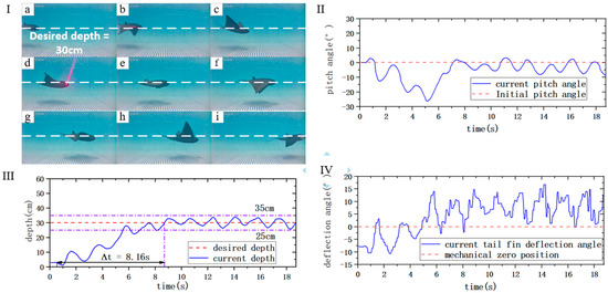
Figure 8.
Frame diagram and data plot of the depth holding experiment. (I) Swimming frame diagram of the manta robot, where (a)–(i) represents the time order. (II) Pitch angle data graph of the manta robot. (III) Depth data graph of the manta robot. (IV) Data plot of tail fin deflection angle of the manta robot.
Figure 9 shows the video frames and data plot obtained during the swimming of the manta robot. At the beginning of the experiment, the heading angle of the manta robot was 79° and the desired heading angle was 76. After about 2.5 s, the manta robot was stabilized at the desired heading, and the heading error after stable swimming was within 3°, which showed that the heading controller we designed had good stability. It should also be pointed out that since the change in the heading angle was within 10° during the whole process of heading-holding swimming, the heading error during the whole motion did not reach the error threshold of motion switching; therefore, only the change of amplitude during the motion and the change curve of the amplitude difference is shown in Figure 9III. From the experimental results, it can be seen that the manta robot has good heading control and depth control capability.
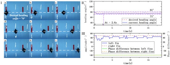
Figure 9.
Frame diagram and data plot of the heading holding experiment. (I) Swimming frame diagram of the manta robot, where (a)–(i) represents the time order. (II) Heading angle data graph of the manta robot. (III) Data plot of pectoral fin motion parameters of the manta robot.
4.2. Heading Switching Experiment
To verify the motion control capability of the manta robot under the condition of abrupt change in the desired heading angle, we conducted 90°, 180°, and 360° heading switching experiments.
Figure 10 shows the frame diagram of the moving process and the experimental data diagram of the experimental process when the manta robot’s desired heading was changed by 90°. Experiments A and B were designed to compare and verify the performance of the classical S-plane controller with the fuzzy S-plane controller based on the transition value function for the desired angle change of 90°. The control parameters k1 and k2 of the classical S-plane controller were determined to be 4 and 3 by the trial-and-error method. The experimental results are shown in Figure 10II. In the process of heading error elimination, the overshoot of the classical S-plane controller was about 27.5°, and the overshoot of the fuzzy S-plane controller based on the transition value function was about 11.4°, which is smaller. When the course switch was completed, the errors of the classical S-plane controller and the fuzzy S-plane controller based on the transition value function were and , respectively. This means that the effect of a fuzzy S-plane controller based on the transition value function was improved compared to the classical S-plane controller.
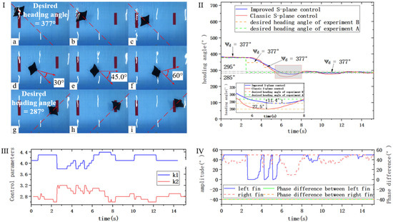
Figure 10.
Heading switching 90° experiment. (I) Swimming frame diagram of the manta robot, where (a)–(i) represents the time order. (II) Heading angle data graph of the manta robot. (III) Controller parameter change curve graph. (IV) Data plot of pectoral fin motion parameters of the manta robot.
For the control process using the fuzzy S-plane control method based on the transition value function, the sequence of the moving process of the manta robot captured by the camera is shown in Figure 10I. The whole process lasts for 15.2 s, the manta robot starts to switch the heading at about 2.45 s and reaches the new desired heading position at about 7.85 s. The motion parameters of the pectoral fins are shown in Figure 10IV. In the experiment, the heading error threshold for pectoral fin motion mode switching was set to 45°, and since the transition process divides the 90° heading switch int, three 30° expected heading angle switches, in this experiment, the manta robot only moves with the difference in amplitude.
To verify the control effect of the manta robot in the case of a larger heading change, the experiments were conducted by choosing the working conditions of 180° and 360° for the desired heading angle change. The experimental results and the experimental frame diagram when swimming are shown in Figure 11.
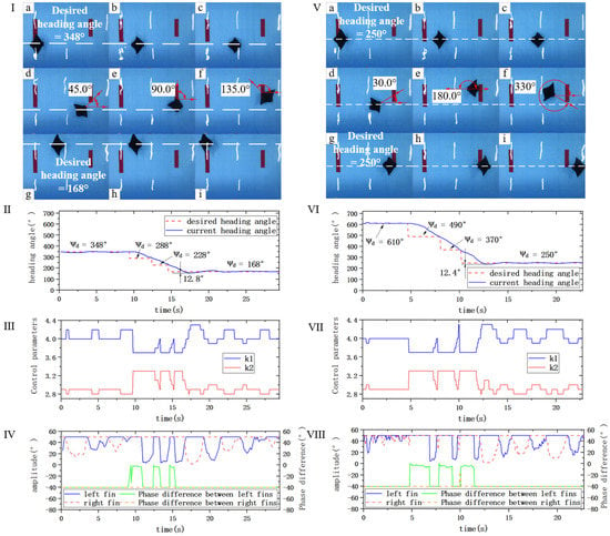
Figure 11.
Heading switching of 180° and 360° experiments. (I) Swimming frame diagram of the manta robot with heading angle switching 180°, where (a)–(i) represents the time order. (II) Heading angle data graph of the manta robot with heading angle switching 180°. (III) Con-troller parameter change curve graph with heading angle switching 180°. (IV) Data plot of pectoral fin motion parameters of the manta robot with heading angle switching 180°. (V) Swimming frame diagram of the manta robot with heading angle switching 360°, where (a)–(i) represents the time order. (VI) heading angle data graph of the manta robot with heading angle switching 360°. (VII) Controller parameter change curve graph with heading angle switching 360°. (VIII) Data plot of pectoral fin motion parameters of the manta robot with heading angle switching 360°.
In both sets of experiments, the manta robot was first required to swim steadily at the current heading angle. The experimental frame diagram when the desired heading angle changed 180° is shown in Figure 11I. As shown in Figure 11II, the manta robot started the heading angle switch at about 12.0 s after starting, and finished the 180° heading angle adjustment after 9.6 s, then continued to swim on that heading, and the parameters of the controller changed in the process as shown in Figure 11III. The motion parameters of the pectoral fins are shown in Figure 11IV. In the whole swimming process, the overshoot was 12.8°, When the heading change was completed, the heading angle error was within . The experimental frame diagram when the desired heading angle change 360° is shown in Figure 11V. As shown in Figure 11VI, the manta robot completed 360° of heading change after 4.65 s, and the overshoot during the control process was 12.4°. When the heading change was completed, the heading angle error was within . The controller parameters of this experiment changed as shown in Figure 11VII, and the motion parameters of the pectoral fins are shown in Figure 11VIII. In the two heading switching experiments, the same three times of heading transition processes were realized, but the change in the desired heading angle was 60° in each experiment when the heading angle switched 180°, and 120° in each experiment when the heading angle switched 360°. In the experiment where the heading angle switched 360°, the error in the heading angle of the manta robot was larger at the beginning of each transition process, and the controller controlled the pectoral fin of the manta robot to maintain the large parameter movement for a higher proportion of time; therefore, although the angle that the manta robot needed to turn was larger when switching 360° than when switching 180°, the time to complete the heading switch was shorter. The experiment verified the effectiveness and stability of the controller when the desired heading angle was changed substantially.
5. Conclusions
In this paper, the depth controller and heading controller of the manta robot were designed based on the S-plane control method. Firstly, the classical S-plane controller was improved with asymmetric output to design the depth controller based on the asymmetric S-plane by combining the longitudinal plane motion characteristics of the manta robot. Secondly, because the horizontal plane motion task of the manta robot is more complex and diverse, to meet the needs of different desired heading angle changes, a heading transition value function was introduced into the heading controller to decompose the large desired heading angle changes, while the fuzzy controller was used to adjust the controller parameters and realize the online correction of the controller parameters. Finally, heading and depth-keeping experiments as well as heading-switching experiments were carried out in an indoor pool. The experimental results show that the depth error was within cm and the heading error was within , and the overshoot of the improved S-plane heading control was small compared with the classical S-plane heading controller; additionally, the error was smaller after the completion of heading switching, which proves the feasibility and reliability of the manta robot control system.
In the future, we will consider improving the perception capability of the manta robot and improving the autonomous movement capability of the manta robot.
Author Contributions
Supervision, Y.C. (Yong Cao), Y.C. (Yonghui Cao), G.P. and Q.H.; writing—original draft, Y.H.; writing—review and editing, Y.H. and Y.C. (Yong Cao); experiment, Y.H., Y.X. and D.Z.; Data curation, Y.H., Y.X., S.M. and D.Z. All authors have read and agreed to the published version of the manuscript.
Funding
This research was funded by the National Natural Science Foundation of China (Grant No. 52001260, 51879220); the National Key Research and Development Program of China (Grant No. 2020YFB1313200); the Fundamental Research Funds for the Central Universities (D500210943, D5000210956, D5000210944).
Institutional Review Board Statement
Not applicable.
Informed Consent Statement
Not applicable.
Data Availability Statement
Not applicable.
Acknowledgments
The authors would like to thank all students and engineers for their assistance during the prototype construction and experiments at the School of Marine Science and Technology of Northwestern Polytechnical University.
Conflicts of Interest
The authors declare no conflict of interest.
References
- Neveln, I.D.; Bai, Y.; Snyder, J.B.; Solberg, J.R.; Curet, O.M.; Lynch, K.M.; MacIver, M.A. Biomimetic and bio-inspired robotics in electric fish research. J. Exp. Biol. 2013, 216, 2501–2514. [Google Scholar] [CrossRef] [PubMed]
- Aly, A.A.; The Vu, M.; El-Sousy, F.F.M.; Alotaibi, A.; Mousa, G.; Le, D.-N.; Mobayen, S. Fuzzy-Based Fixed-Time Nonsingular Tracker of Exoskeleton Robots for Disabilities Using Sliding Mode State Observer. Mathematics 2022, 10, 3147. [Google Scholar] [CrossRef]
- Alattas, K.A.; Mobayen, S.; Din, S.U.; Asad, J.H.; Fekih, A.; Assawinchaichote, W.; Vu, M.T. Design of a Non-Singular Adaptive Integral-Type Finite Time Tracking Control for Nonlinear Systems With External Disturbances. IEEE Access 2021, 9, 102091–102103. [Google Scholar] [CrossRef]
- Vu, M.T.; Le Thanh, H.N.N.; Huynh, T.-T.; Thang, Q.; Duc, T.; Hoang, Q.-D.; Le, T.-H. Station-Keeping Control of a Hovering Over-Actuated Autonomous Underwater Vehicle Under Ocean Current Effects and Model Uncertainties in Horizontal Plane. IEEE Access 2021, 9, 6855–6867. [Google Scholar] [CrossRef]
- Thanh, H.L.N.N.; Vu, M.T.; Mung, N.X.; Nguyen, N.P.; Phuong, N.T. Perturbation Observer-Based Robust Control Using a Multiple Sliding Surfaces for Nonlinear Systems with Influences of Matched and Unmatched Uncertainties. Mathematics 2020, 8, 1371. [Google Scholar] [CrossRef]
- Mobayen, S.; Bayat, F.; Din, S.; Vu, M.T. Barrier function-based adaptive nonsingular terminal sliding mode control technique for a class of disturbed nonlinear systems. ISA Trans. 2022. [Google Scholar] [CrossRef]
- Vu, M.T.; Alattas, K.A.; Bouteraa, Y.; Rahmani, R.; Fekih, A.; Mobayen, S.; Assawinchaichote, W. Optimized Fuzzy Enhanced Robust Control Design for a Stewart Parallel Robot. Mathematics 2022, 10, 1917. [Google Scholar] [CrossRef]
- Mokhtare, Z.; Vu, M.T.; Mobayen, S.; Fekih, A. Design of an LMI-Based Fuzzy Fast Terminal Sliding Mode Control Approach for Uncertain MIMO Systems. Mathematics 2022, 10, 1236. [Google Scholar] [CrossRef]
- Martins, A.; Almeida, J.; Almeida, C.; Matias, B.; Kapusniak, S.; Silva, E. EVA a Hybrid ROV/AUV for Underwater Mining Operations Support. In Proceedings of the 2018 OCEANS—MTS/IEEE Kobe Techno-Oceans (OTO), Kobe, Japan, 28–31 May 2018; pp. 1–7. [Google Scholar] [CrossRef]
- Dunbabin, M.; Roberts, J.; Usher, K.; Winstanley, G.; Corke, P. A Hybrid AUV Design for Shallow Water Reef Navigation. In Proceedings of the 2005 IEEE International Conference on Robotics and Automation, Barcelona, Spain, 18–22 April 2005; pp. 2105–2110. [Google Scholar] [CrossRef]
- Eichhorn, M.; Ament, C.; Jacobi, M.; Pfuetzenreuter, T.; Karimanzira, D.; Bley, K.; Boer, M.; Wehde, H. Modular AUV System with Integrated Real-Time Water Quality Analysis. Sensors 2018, 18, 1837. [Google Scholar] [CrossRef]
- Gao, Z.; Guo, G. Fixed-Time Leader-Follower Formation Control of Autonomous Underwater Vehicles With Event-Triggered Intermittent Communications. IEEE Access 2018, 6, 27902–27911. [Google Scholar] [CrossRef]
- Wynn, R.B.; Huvenne, V.A.I.; Le Bas, T.P.; Murton, B.J.; Connelly, D.P.; Bett, B.J.; Ruhl, H.A.; Morris, K.J.; Peakall, J.; Parsons, D.R.; et al. Autonomous Underwater Vehicles (AUVs): Their past, present and future contributions to the advancement of marine geoscience. Mar. Geol. 2014, 352, 451–468. [Google Scholar] [CrossRef]
- Yu, C.; Xiang, X.; Lapierre, L.; Zhang, Q. Robust Magnetic Tracking of Subsea Cable by AUV in the Presence of Sensor Noise and Ocean Currents. IEEE J. Ocean. Eng. 2018, 43, 311–322. [Google Scholar] [CrossRef]
- Huang, S.-W.; Chen, E.; Guo, J. Efficient Seafloor Classification and Submarine Cable Route Design Using an Autonomous Underwater Vehicle. IEEE J. Ocean. Eng. 2018, 43, 7–18. [Google Scholar] [CrossRef]
- Villar, S.A.; Acosta, G.G.; Sousa, A.L.; Rozenfeld, A. Evaluation of an Efficient Approach for Target Tracking from Acoustic Imagery for the Perception System of an Autonomous Underwater Vehicle. Int. J. Adv. Robot. Syst. 2014, 11, 24. [Google Scholar] [CrossRef]
- Review of Biomimetic Underwater Robots Using Smart Actuators|SpringerLink. Available online: https://link.springer.com/article/10.1007/s12541-012-0171-7 (accessed on 27 September 2022).
- Fish, F.E.; Kocak, D.M. Biomimetics and Marine Technology. Mar. Technol. Soc. J. 2011, 45, 8–13. [Google Scholar] [CrossRef]
- Villanueva, A.; Smith, C.; Priya, S. A biomimetic robotic jellyfish (Robojelly) actuated by shape memory alloy composite actuators. Bioinspir. Biomim. 2011, 6, 036004. [Google Scholar] [CrossRef]
- Sfakiotakis, M.; Lane, D.M.; Davies, J.B.C. Review of fish swimming modes for aquatic locomotion. IEEE J. Ocean. Eng. 1999, 24, 237–252. [Google Scholar] [CrossRef]
- Yu, J.; Wang, M.; Dong, H.; Zhang, Y.; Wu, Z. Motion Control and Motion Coordination of Bionic Robotic Fish: A Review. J. Bionic. Eng. 2018, 15, 579–598. [Google Scholar] [CrossRef]
- Wang, S.; Wang, Y.; Wei, Q.; Tan, M.; Yu, J. A Bio-Inspired Robot With Undulatory Fins and Its Control Methods. IEEE/ASME Trans. Mechatron. 2017, 22, 206–216. [Google Scholar] [CrossRef]
- Qu, Y.; Guo, Z.; Zhang, G.; Gao, X.-L.; Jin, F. A New Model for Circular Cylindrical Kirchhoff-Love Shells Incorporating Microstructure and Flexoelectric Effects. J. Appl. Mech. 2022, 89, 121010. [Google Scholar] [CrossRef]
- Qu, Y.L.; Zhang, G.Y.; Gao, X.-L.; Jin, F. A new model for thermally induced redistributions of free carriers in centrosymmetric flexoelectric semiconductor beams. Mech. Mater. 2022, 171, 104328. [Google Scholar] [CrossRef]
- Qu, Y.; Jin, F.; Yang, J. Torsion of a piezoelectric semiconductor rod of cubic crystals with consideration of warping and in-plane shear of its rectangular cross section. Mech. Mater. 2022, 172, 104407. [Google Scholar] [CrossRef]
- Qu, Y.; Jin, F.; Yang, J. Temperature-induced potential barriers in piezoelectric semiconductor films through pyroelectric and thermoelastic couplings and their effects on currents. J. Appl. Phys. 2022, 131, 094502. [Google Scholar] [CrossRef]
- Tuna Robotics: A High-Frequency Experimental Platform Exploring the Performance Space of Swimming Fishes|Science Robotics. Available online: https://www.science.org/doi/abs/10.1126/scirobotics.aax4615 (accessed on 27 September 2022).
- Aubin, C.A.; Choudhury, S.; Jerch, R.; Archer, L.A.; Pikul, J.H.; Shepherd, R.F. Electrolytic vascular systems for energy-dense robots. Nature 2019, 571, 51–57. [Google Scholar] [CrossRef] [PubMed]
- Chen, X.; Yu, J.; Wu, Z.; Meng, Y.; Kong, S. Toward a Maneuverable Miniature Robotic Fish Equipped With a Novel Magnetic Actuator System. IEEE Trans. Syst. Man Cybern. Syst. 2020, 50, 2327–2337. [Google Scholar] [CrossRef]
- Zhou, C.; Low, K.H. Design and Locomotion Control of a Biomimetic Underwater Vehicle With Fin Propulsion. IEEE/ASME Trans. Mechatron. 2012, 17, 25–35. [Google Scholar] [CrossRef]
- Low, K.H.; Zhou, C.; Seet, G.; Bi, S.; Cai, Y. Improvement and testing of a robotic manta ray (RoMan-III). In Proceedings of the 2011 IEEE International Conference on Robotics and Biomimetics, Karon Beach, Thailand, 7–11 December 2011; pp. 1730–1735. [Google Scholar] [CrossRef]
- Yan, Q.; Wang, L.; Liu, B.; Yang, J.; Zhang, S. A Novel Implementation of a Flexible Robotic Fin Actuated by Shape Memory Alloy. J. Bionic. Eng. 2012, 9, 156–165. [Google Scholar] [CrossRef]
- Arastehfar, S.; Chew, C.-M.; Jalalian, A.; Gunawan, G.; Yeo, K.S. A Relationship Between Sweep Angle of Flapping Pectoral Fins and Thrust Generation. J. Mech. Robot. 2018, 11, 011014. [Google Scholar] [CrossRef]
- Wang, R.; Wang, S.; Wang, Y. A Hybrid Heading Control Scheme for a Biomimetic Underwater Vehicle. In Proceedings of the 26th International Ocean and Polar Engineering Conference, Rhodes, Greece, 26 June 2016. [Google Scholar]
- Liu, Q.; Chen, H.; Wang, Z.; He, Q.; Chen, L.; Li, W.; Li, R.; Cui, W. A Manta Ray Robot with Soft Material Based Flapping Wing. J. Mar. Sci. Eng. 2022, 10, 962. [Google Scholar] [CrossRef]
- Zhang, D.; Pan, G.; Cao, Y.; Huang, Q.; Cao, Y. A Novel Integrated Gliding and Flapping Propulsion Biomimetic Manta-Ray Robot. J. Mar. Sci. Eng. 2022, 10, 924. [Google Scholar] [CrossRef]
- Zhong, Y.; Xie, F.; Song, J.; Du, R. Implementation and depth control of an active-and-compliant propelled robot fish. In Proceedings of the 2017 IEEE International Conference on Robotics and Biomimetics (ROBIO), Macao, China, 5–8 December 2017; pp. 2331–2336. [Google Scholar] [CrossRef]
- Cao, Y.; Xie, Y.; Ma, S.; Zhang, D.; Hao, Y.; He, Y.; Cao, Y. Control of Robotic Manta Based on T-S Fuzzy Neural Network. In Proceedings of the 2021 International Conference on Autonomous Unmanned Systems (ICAUS 2021); Wu, M., Niu, Y., Gu, M., Cheng, J., Eds.; Springer: Singapore, 2022; pp. 2813–2822. [Google Scholar] [CrossRef]
- Wei, Q.; Wang, S.; Wang, Y.; Zhou, C.; Tan, M. Course and Depth Control for a Biomimetic Underwater Vehicle—RobCutt-I. Int. J. Offshore Polar Eng. 2015, 25, 81–87. [Google Scholar] [CrossRef]
- Yu, J.; Liu, J.; Wu, Z.; Fang, H. Depth Control of a Bioinspired Robotic Dolphin Based on Sliding-Mode Fuzzy Control Method. IEEE Trans. Ind. Electron. 2018, 65, 2429–2438. [Google Scholar] [CrossRef]
- Yan, Z.; Yang, H.; Zhang, W.; Lin, F.; Gong, Q.; Zhang, Y. Bionic fish tail design and trajectory tracking control. Ocean Eng. 2022, 257, 111659. [Google Scholar] [CrossRef]
- Chen, J.; Yin, B.; Wang, C.; Xie, F.; Du, R.; Zhong, Y. Bioinspired Closed-loop CPG-based Control of a Robot Fish for Obstacle Avoidance and Direction Tracking. J. Bionic. Eng. 2021, 18, 171–183. [Google Scholar] [CrossRef]
- Cao, Y.; Xie, Y.; He, Y.; Pan, G.; Huang, Q.; Cao, Y. Bioinspired Central Pattern Generator and T-S Fuzzy Neural Network-Based Control of a Robotic Manta for Depth and Heading Tracking. J. Mar. Sci. Eng. 2022, 10, 758. [Google Scholar] [CrossRef]
- Hao, Y.; Cao, Y.; Cao, Y.; Huang, Q.; Pan, G. Course Control of a Manta Robot Based on Amplitude and Phase Differences. J. Mar. Sci. Eng. 2022, 10, 285. [Google Scholar] [CrossRef]
- Zhang, L.; Pang, Y.; Su, Y.; Zhao, F.; Qin, Z. Expert S-surface control for autonomous underwater vehicles. J. Mar. Sci. Appl. 2008, 7, 236–242. [Google Scholar] [CrossRef]
- Yushan, S.; Lei, W.; Yueming, L.; Liwei, L.; Guocheng, Z. S plane control based on parameters optimization with simulated annealing for underwater vehicle. In Proceedings of the 2011 International Conference on Electronic & Mechanical Engineering and Information Technology, Harbin, China, 12–14 August 2011; pp. 552–556. [Google Scholar] [CrossRef]
Publisher’s Note: MDPI stays neutral with regard to jurisdictional claims in published maps and institutional affiliations. |
© 2022 by the authors. Licensee MDPI, Basel, Switzerland. This article is an open access article distributed under the terms and conditions of the Creative Commons Attribution (CC BY) license (https://creativecommons.org/licenses/by/4.0/).