Article

Research on the Matching Characteristics of the Impellers and Guide Vanes of Seawater Desalination Pumps with High Capacity and Pressure

1
National Research Center of Pumps, Jiangsu University, No. 301, Xuefu Road, Jingkou District, Zhenjiang 212013, China
2
Institute of Fluid Engineering Equipment Technology, Jiangsu University, Zhenjiang 212009, China
*
Authors to whom correspondence should be addressed.
J. Mar. Sci. Eng. 2022, 10(1), 115; https://doi.org/10.3390/jmse10010115
Submission received: 9 December 2021 / Revised: 29 December 2021 / Accepted: 4 January 2022 / Published: 15 January 2022
(This article belongs to the Section Ocean Engineering)

Abstract

:
This paper presents the matching characteristics of impellers and guide vanes of high capacity and pressure seawater desalination pumps by using computational fluid dynamics (CFD). The single-stage pump is numerically calculated, and its external characteristics are consistent with the test results of model pump. Taking this scheme as a prototype, the research is carried out from three aspects: (i) the impeller blade outlet width; (ii) the number of impeller and guide vane blades; and (iii) the area ratio of impeller outlet to guide vane inlet. The results indicate that the blade outlet width significantly affects the pump head and efficiency. Appropriately increasing the number of guide vane blades or changing the number of impeller blades can improve efficiency and expand the high-efficiency area. Additionally, increasing the throat area of the guide vane has the opposite effect on the large flow and small flow area of the pump. An optimized hydraulic model design scheme is obtained.

1. Introduction

The centrifugal pump is used in high capacity and pressure seawater desalination engineering, with a complicated internal flow. The mechanical, hydraulic, and volume loss are closely related to the geometric parameters of the overflow components. Different parameter combinations have a great impact on the pump’s performance, which makes the design process complex and time consuming. Researchers have been concerned about how to determine and optimize geometric parameters to reduce energy consumption and improve performance [1,2,3,4].
Due to the wasteful human and material resources, long cycles, and other adverse factors, the model test seriously restricts researchers from making a significant breakthrough in optimizing geometric parameters. In recent years, with the improvement of computer performance and the development of technology, more and more scholars have used CFD technology to analyze the flow field, predict the performance, and optimize the parameters of pumps [5,6,7,8,9]. Ji et al. [10] used the Wray–Agarwal (WA) turbulence model to predict the internal and external characteristics of centrifugal pumps, which was in good agreement with the experimental results, proving the accuracy of the CFD method. Shojaeefard et al. [11] studied the effects of different impeller channel widths and outlet angles on centrifugal pump performance parameters. The experimental and numerical simulation results showed that the improved impeller can effectively improve the head and efficiency of the centrifugal pump. Wu et al. [12] studied the applicability of different turbulence models in the numerical calculation of centrifugal pumps based on the comparative analysis of test and numerical simulation. They analyzed the flow law inside the pump. Guo et al. [13] optimized the axial impeller shape, blade number, blade airfoil, inlet and outlet angle, and other parameters based on CFD analysis to improve the pump performance. Mojaddam et al. [14] optimized the impeller structure of the centrifugal pump and improved the efficiency and total head by discussing the length of the splitter blade, the leading edge position of the main blade and the splitter blade, and the distance between two adjacent splitter blades. Fu et al. [15] conducted pressure pulsation tests on impeller structures with different staggered angles, analyzing the time domain of pressure signal using the statistical method and fast Fourier transform (FFT) and successfully established the relationship between impeller staggered angle and pressure fluctuation. Alemi et al. [16] studied the influence of main geometric parameters of volute on pump performance and radial force, including velocity or angular momentum constant method design, section shape, and outlet diffuser shape, and found that a circular section volute with radial diffuser has a higher head and efficiency. Nataraj et al. [17] modified the key design parameters of the pump by using the central composite design and evaluated the characteristics of the pump by studying different impeller inlet diameters, blade outlet angles, and blade outlet widths. Jafarzadeh et al. [18] studied the influence of the number of blades on the pump efficiency and found that the blade position relative to the volute tongue has a great influence on the separation. Bellary et al. [19] used the three-dimensional Navier–Stokes analysis method to conduct single-objective optimization on the shape of impeller blades of centrifugal pumps. By changing the inlet and outlet angle of the blade to improve the hydraulic efficiency, it was found that adjusting the outlet angle has a greater impact on the efficiency than adjusting the inlet angle. Tan et al. [20] used CFX software to conduct an unsteady numerical simulation of the whole flow field in the pump under different guide vane outlet angles and found that the guide vane outlet angle has a great impact on the pump head and efficiency. When the outlet angle is 10°, the pump head and efficiency are the best. Li et al. [21] analyzed the influences of blade outlet width, blade outlet angle, and blade envelope angle on efficiency, and studied the matching characteristics of different volute tongue angles and optimized impellers. However, the above research mainly focuses on the optimization of pump structure geometric parameters.
The comprehensive performance of a high capacity and pressure pump is related to the performance of single flow passage components of impellers and guide vanes and their matching performance. Qi et al. [22] used large-eddy simulation (LES) to study the impact of different blade numbers in impellers and volutes matching on pump efficiency. They found that excessive blades increase the work performed by blade surface friction, resulting in reduced pump head and efficiency. Wang et al. [23] used fluent software to study different parameter combinations of impellers and guide vanes of centrifugal pumps and found that pump performance decreases with the increase in matching clearance between impeller and guide vane, and the best matching performance also changes under variable working conditions. Kong et al. [24] used the area ratio principle for reference to carry out numerical simulation of the single-stage impeller and radial guide vane and found that the throat area of the guide vane has a great impact on the performance of the centrifugal pump, and the appropriate optimal design of positive guide vane can improve the efficiency of centrifugal pump. Kaya [25] carried out an experimental study on the collocation of seven-blade guide vanes with three- or four-blade impellers. The study found that the matching of impeller and guide vane with different blade numbers had a remarkable influence on pump efficiency. Tsukamoto et al. [26] studied the pressure fluctuation inside the pump by numerical simulation. They pointed out that the interaction between impeller and guide vane is the main influencing factor of pressure fluctuation inside guide vane. It can be concluded that, regardless of whether the same impeller uses a different guide vane or the same guide vane uses a different impeller, the performance of the pump significantly changes. However, for a long time, people have been paying more attention to the single hydraulic performance of impeller and guide vane, but there is a lack of in-depth research on their matching relationship.
In this study, based on the excellent hydraulic model of seawater desalination high-pressure pump, the matching characteristics of the impeller and guide vane of a large seawater desalination high-pressure pump are discussed regarding three aspects: different outlet width of impeller blade, the number of impeller and guide vane blades, and area ratio of impeller outlet to guide vane inlet. We hope to provide some reference for the optimization design of independent desalination high-pressure pumps.

2. Calculation Model

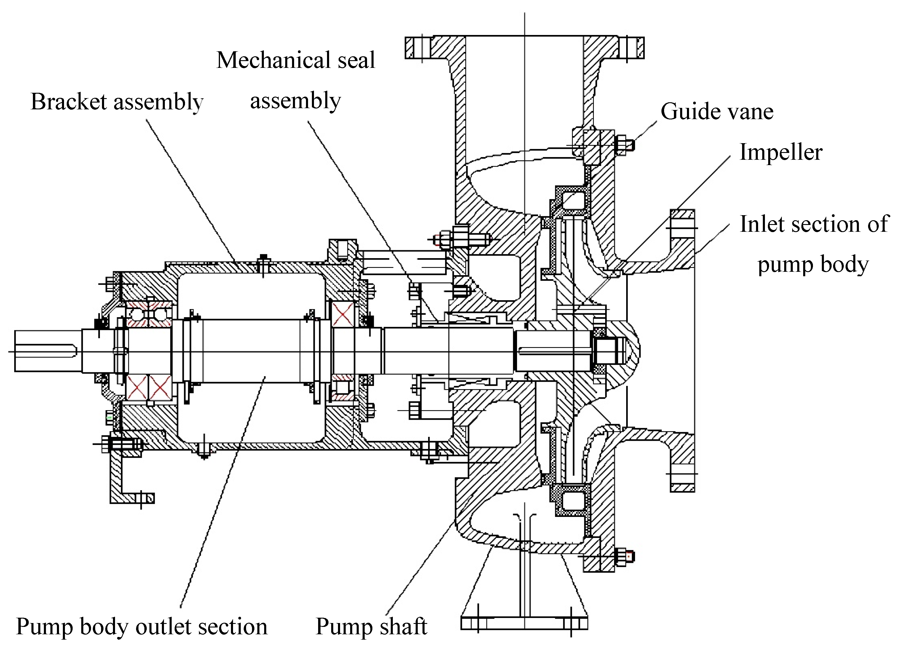
2.1. Structural Form of the High-Pressure Pump

In this study, the single-stage pump was taken as the object of hydraulic research. According to the research of Wang et al. [27], a group of optimum hydraulic model design schemes was selected employing numerical calculations. The structure of the single-stage model pump is shown in Figure 1. The main geometric parameters of the impeller and guide vane are shown in Table 1.

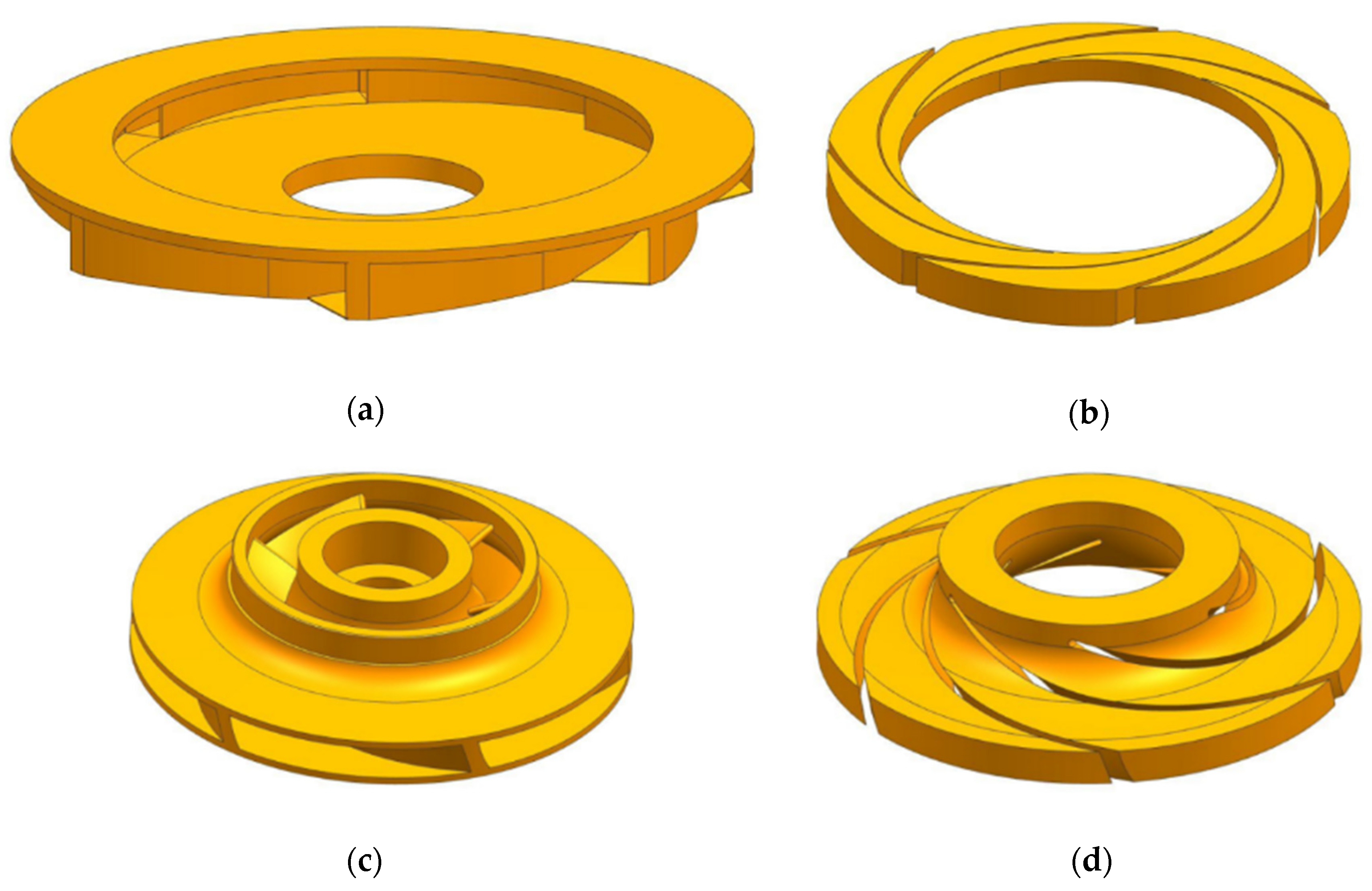
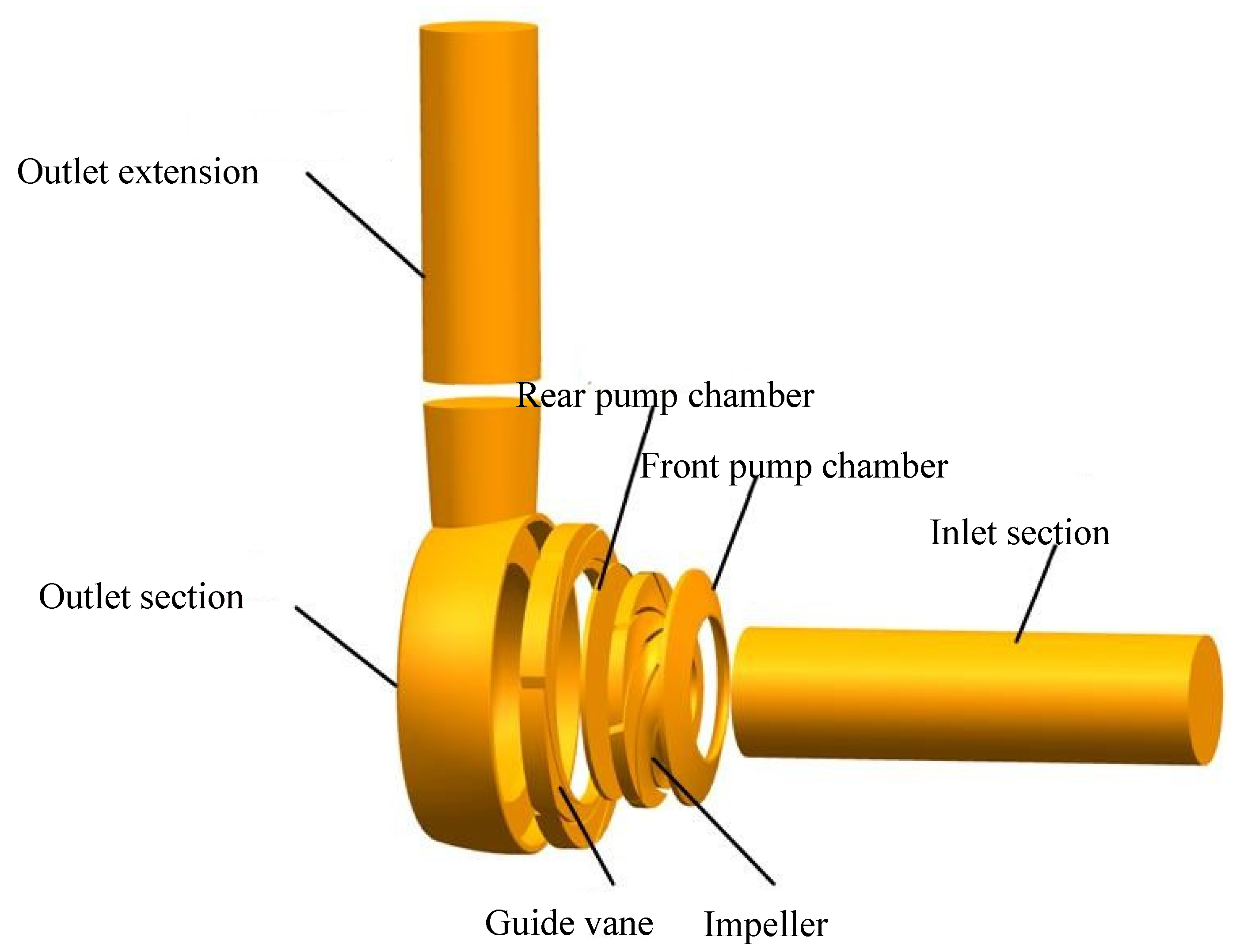
2.2. Three-Dimensional Modeling
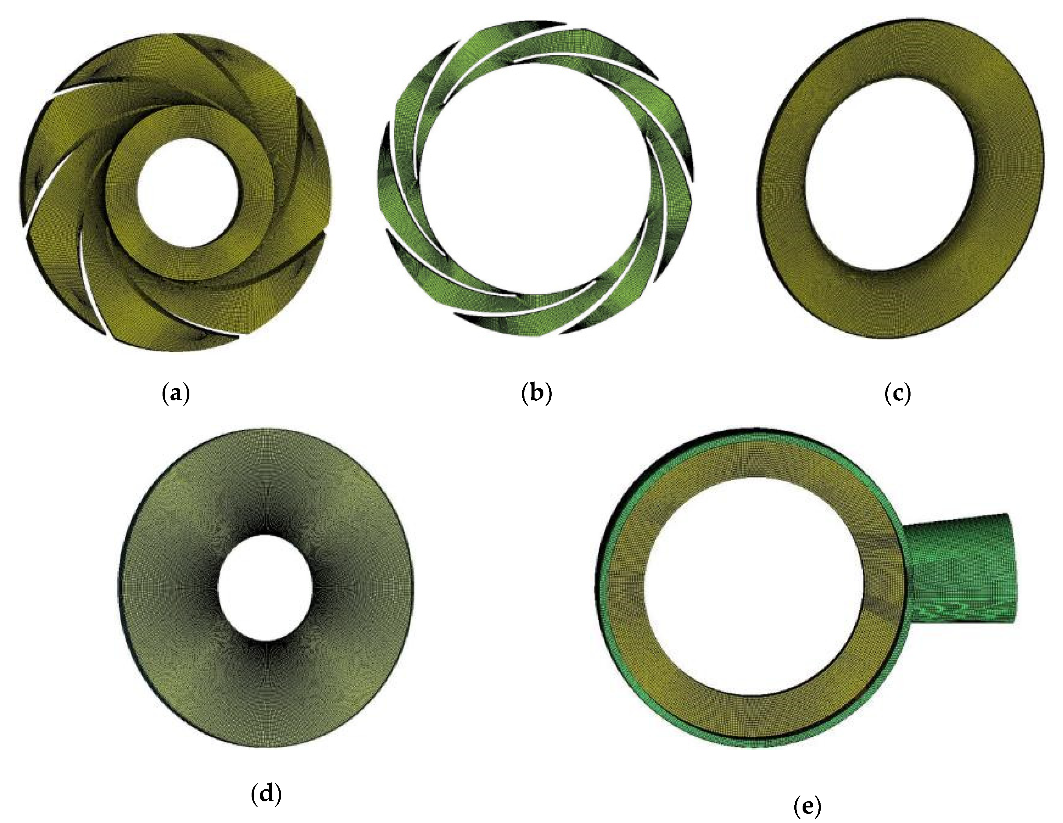
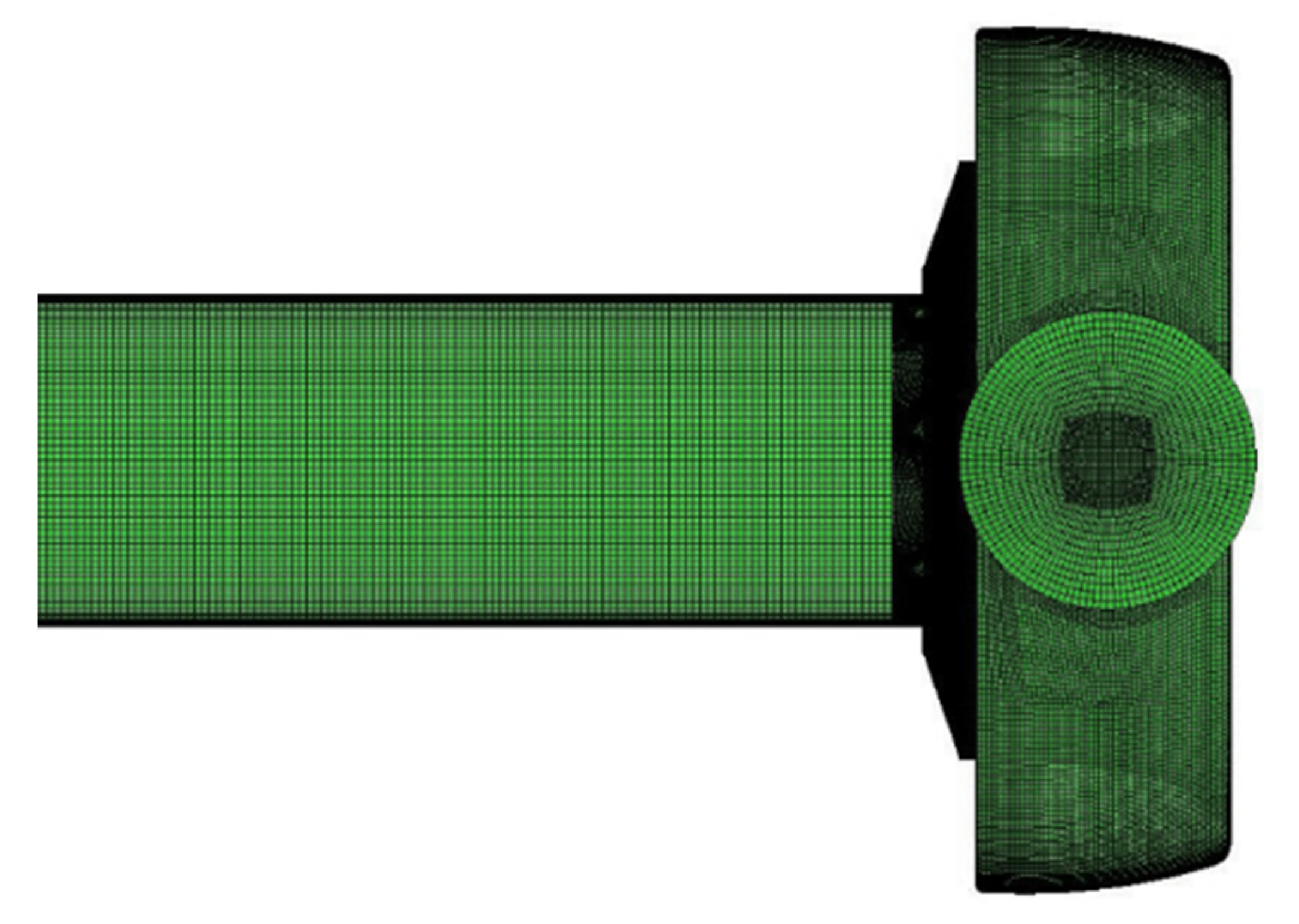
The liquid from the impeller flows directly to the outlet section after passing through the positive guide vane, so the guide vane in the single-stage pump model has only a positive guide vane and no anti-guide vane. The solid structure of impeller and guide vane is shown in Figure 2, and the flow computational domain is shown in Figure 3. The flow passage parts include the inlet section, impeller, guide vane, front and rear pump chambers, outlet section, and outlet extension section.

2.3. Meshing

ICEM software was used to mesh the fluid calculation domain of the single-stage pump model. Considering the influence of mesh quality on the calculation accuracy, all the structured hexahedral meshes were used in the simulation. Considering the applicability of the pump turbulence model and to ensure that the resolution of the boundary layer and the first grid spacing can bridge the viscous sublayer, the impeller, guide vane, and other flow passage parts were locally densified, and y+ was controlled within 100. y+ can be defined as y + = y u τ / υ , where y is the thickness of the first cell from the wall surface and u τ is the wall frictional velocity. The inlet section and outlet extension section are divided into O-type structured grids, and the overall grid quality is above 0.4. The grid division of each fluid domain is shown in Figure 4 and the assembly diagram of fluid computing domain grid is shown in Figure 5.

2.4. Turbulence Model

The turbulence model adopts the standard k-ε model, which is widely used in centrifugal pump simulation, and its numerical results are in good agreement with the experimental results [28,29,30]. Standard k-ε was proposed by Launder and Spalding in 1972 [31]. The turbulent viscosity is solved by using the results of turbulent kinetic energy and turbulent dissipation rate, and the Reynolds Stress is finally solved according to the Boussinesq hypothesis.
Turbulent kinetic energy k equation:
( ρ k ) t + ( ρ u j k ) x j = x j [ ( μ t σ k + μ ) k x j ] + G k ρ ε
Turbulent dissipation rate ε equation:
( ρ k ) t + ( ρ u j ε ) x j = x j [ ( μ t σ k + μ ) ε x j ] + ε k ( C 1 G k C 2 ρ ε )
where, Gk is the generic term of turbulent kinetic energy k caused by average velocity gradient; C1 and C2 is the empirical constant, C1 = 1.44, C2 = 1.92; and σk and σε are Prandtl numbers corresponding to turbulent kinetic energy k and dissipation rate ε, respectively, σ k   = 1.0 and σ ε = 1.3.
The turbulent viscosity, μ t , is computed by combining them and as follows:
μ t = C μ ρ k 2 ε
where Cμ is a constant, Cμ = 0.09

2.5. Grid Independence Verification

Table 2 shows the head of the single-stage pump model underrated condition calculated by changing the number of grids. As the number of grids increases, the change of head tends to be stable. When the grid number is close to 3.1 million, increasing the number of grids has little effect on the head variation, and the relative error is within ±1%, which meets the requirements of grid independence. Therefore, the grid number is about 3.1 million for numerical simulation.

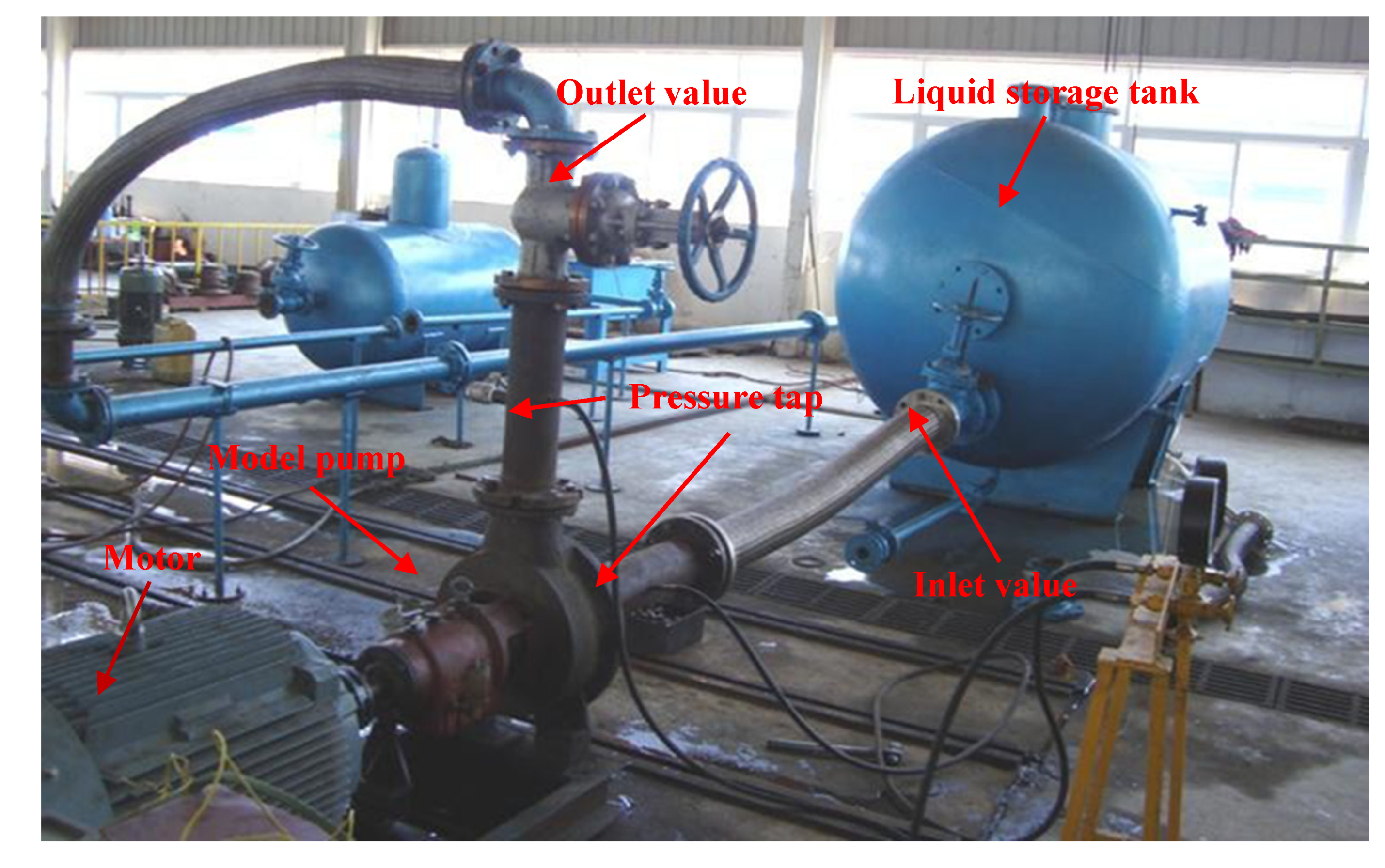
2.6. Comparison between Numerical Simulation and Experiment

The hydraulic model mentioned above was processed into an entity and the external characteristics were tested after assembly. The test bench of the model pump was built, as shown in Figure 6. The test bench comprises a model pump, motor, liquid storage tank, vacuum pump, velocimeter, inlet and outlet valve, flowmeter, etc. The key parameters of the single-stage pump are: Qdes = 650 m3/h, H = 205 m, η = 83%, n = 2980 r/min, and the matching motor power is 442.8 kW. By calculation, the overall uncertainty of pump efficiency is 0.37%, the uncertainty of flow measurement is 0.57%, and the uncertainty of head is 0.23%. All the accuracy meets the standard requirements. It was mainly used for external characteristic tests of the high-pressure pump. The model pump site is shown in Figure 7.
The external characteristics of the high-pressure pump at rated speed were obtained, and the comparison diagrams of numerical simulation and experimental external characteristics curves were drawn as shown in Figure 8. The test results show that the efficiency of the model pump reaches 80.36% at the flow rate Q = 600 m3/h, and the head is 211.13 m. Then, with the flow rate increase, the efficiency continues to increase, and the maximum efficiency reaches 82.43% at the flow rate Q = 782 m3/h, and the head is 182.78 m. The flow continues to increase to Q = 840 m3/h, the head is 169.10 m, and the efficiency can still reach 77%. It indicates that the external characteristic results of the numerical calculation are consistent with the experimental results. Compared with the experimental data, the calculated head, efficiency, and power are all high, which is due to the neglect of the leakage of the impeller inlet, the gap between the impeller and the guide vane, and the relative error between the impeller and guide vane them being small. Under the condition of 1.0Qdes, the error of numerical simulation and test head is 4.2%, and the error under 1.2Qdes is 6.5%, which is within the allowable scope of the project, indicating that the accuracy of numerical calculation is high.
With the increase in the flow rate, the head and efficiency of numerical simulation and experimental measurement decrease significantly. At 1.4Qdes, the simulated head drops to 146.8 m, and the efficiency drops to 72%, which is not conducive to the operation and energy saving of the high-pressure pump. This shows that the hydraulic performance of this scheme still has a large room to improve after 1.3Qdes. To improve the performance of the pump, this study will start from the matching of impeller and guide vane flow field and analyze its influencing factors.

3. Research on Matching the Performance of Impeller and Guide Vane

3.1. Influence of Blade Outlet Width

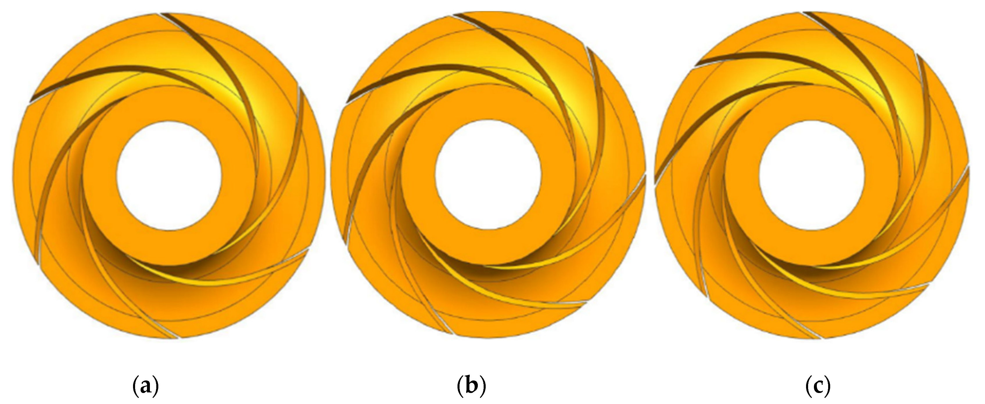
3.1.1. Scheme Design

The blade outlet width b2 is an important parameter affecting pump performance. The most direct influence of the change of blade outlet width on the liquid flow shape is that the size and speed of the liquid flow at the impeller outlet have changed, which has an impact on the flow field at the connection of impeller and guide vane and then brings about the change of pump performance. Choosing an appropriate blade outlet width can effectively improve the flow at the impeller outlet. In this study, four groups of different blade outlet width b2 schemes are designed for research. The three-dimensional modeling of the impeller is shown in Figure 9, and the scheme list is shown in Table 3. The four groups of schemes are numerically calculated in CFX.

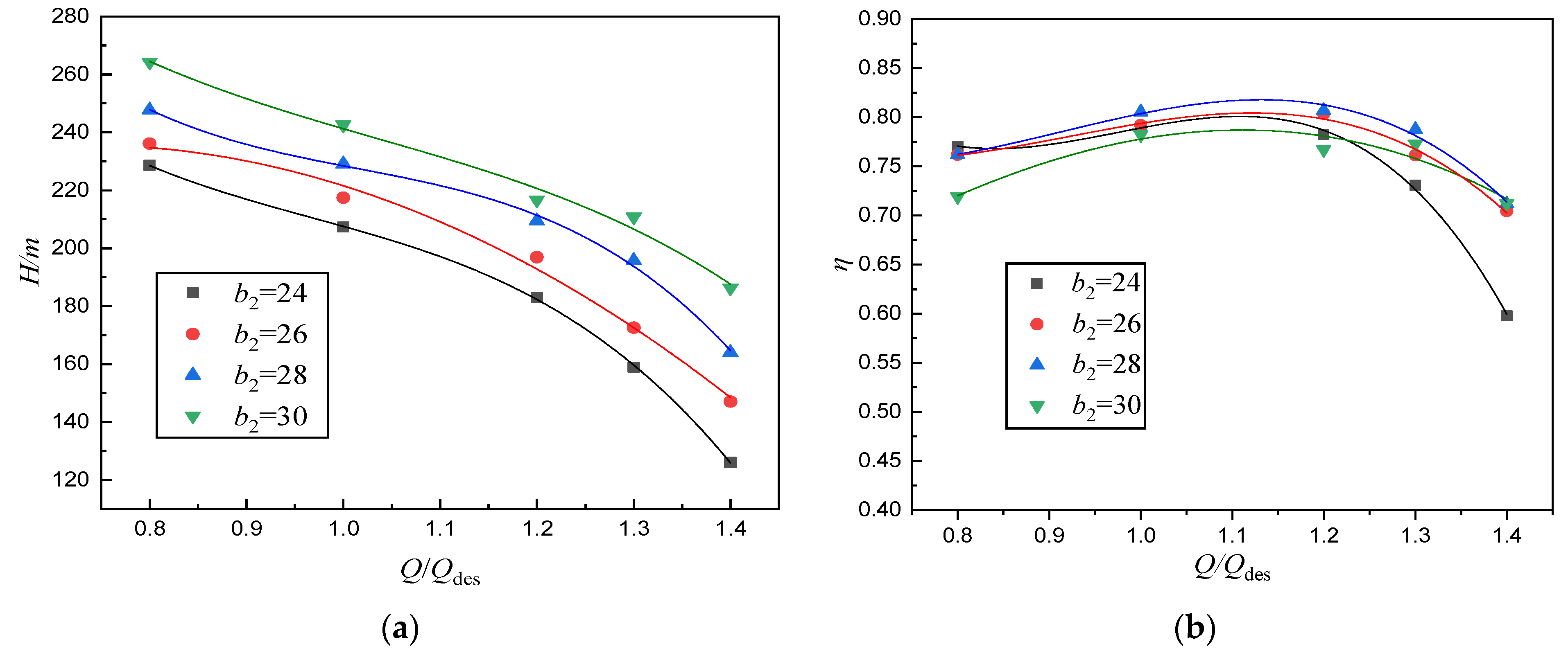
3.1.2. Analysis of External Characteristic Results

Figure 10 shows the external characteristic curves of four groups of different blade outlet width schemes obtained by numerical calculation. The figure below shows that, with the increase in the width of the blade outlet, the pump head and efficiency change accordingly, and the overall change trend of the head is relatively consistent. Furthermore, the change of efficiency is quite different. From b2 = 24 mm to b2 = 30 mm, the head of the pump increases with the increase in b2 at the same operating point. For each scheme, the head decreases with increasing flow rate, and the decrease becomes gentle with the increase in blade outlet width. Comparing the efficiency, it can be found that, with the increase in the blade outlet width, from b2 = 24 mm to b2 = 28 mm, the efficiency of each scheme at each operating point increases, on the whole, while when b2 increases to 30 mm, the efficiency at 1.2Qdes not only decreases significantly but is also lower than other schemes. The comparison of each group shows that the head and efficiency are significantly improved when the blade outlet width increases from b2 = 26 mm to b2 = 28 mm, which indicates that the appropriate increase in blade outlet width can effectively improve the hydraulic performance of the high-pressure pump at high flow rates.

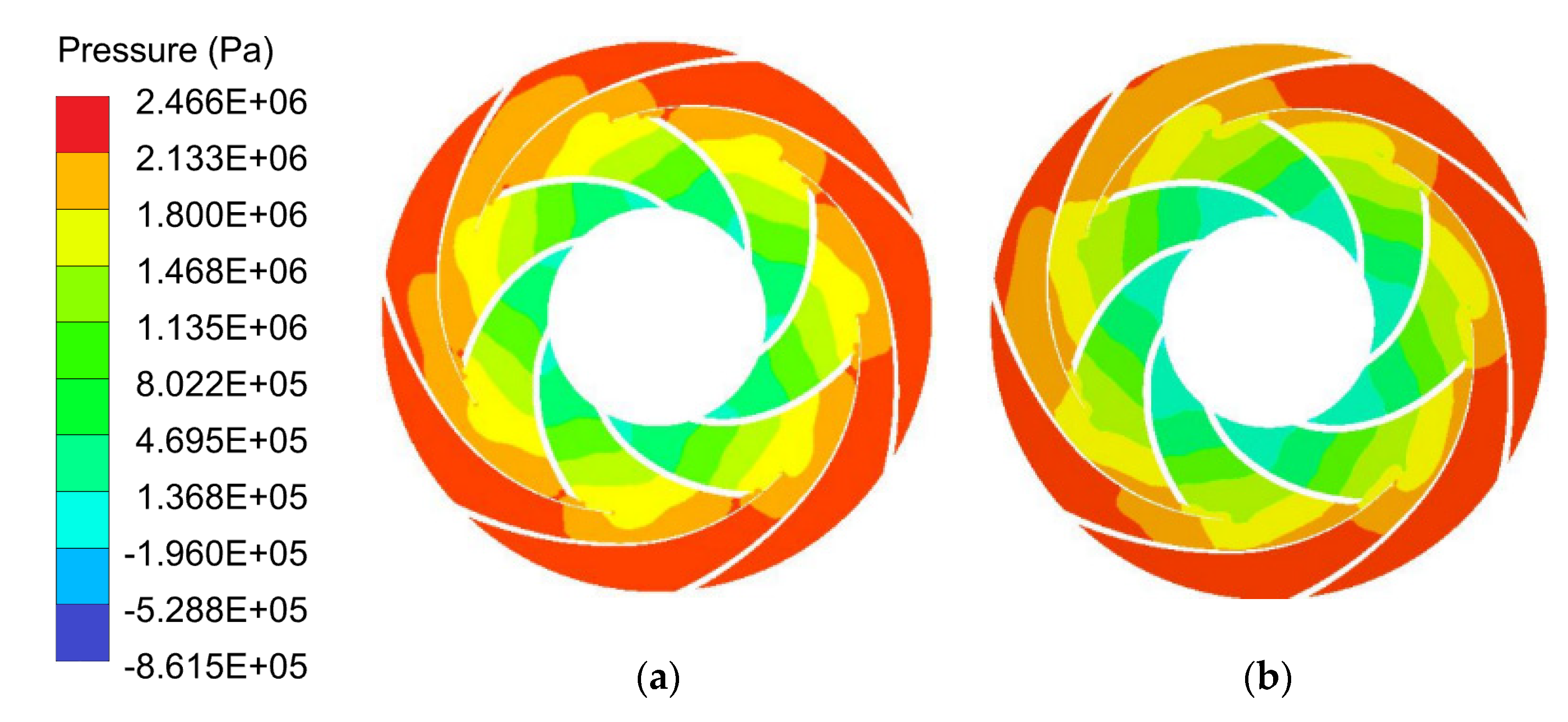
3.1.3. Internal Flow Field Analysis

Figure 11 shows the pressure distribution of impeller and guide vane at 1.2Qdes with different blade outlet widths. It shows a gradual increase in pressure from the inlet to the outlet of the impeller. At the interface between the impeller outlet and the guide vane inlet, the pressure is divided into high-pressure and low-pressure areas. The distribution is asymmetric along the radial direction. The reason is that the rotating work of the impeller makes the pressure in the impeller gradually increase along the flow direction. After the liquid flow enters the positive guide vane, part of the velocity energy is converted into pressure energy. The local high-pressure region is formed, and the pressure distribution is asymmetric due to the changing circumferential position of the impeller and the guide vane. As the blade outlet width increases, the pressure in the impeller increases gradually and further diffuses to the guide vane area. From b2 = 24 mm to b2 = 26 mm, the high-pressure zone in the guide vane decreases. Then, with the further increase in b2, the high-pressure zone in the guide vane increases, and the pressure value also increases with the increase in blade outlet width, which is also the reason why the water head increases with the increase in b2.
Figure 12 shows the velocity distribution of impeller and guide vane at 1.2Qdes with different blade outlet widths. Comparing the four schemes, it can be seen that, under different blade outlet widths, the streamline change law in the impeller passage is relatively consistent, and the flow velocity in the impeller changes in a comparatively even manner. From the impeller inlet to the outlet, the flow velocity increases uniformly. With the increase in b2, the flow velocity in the impeller decreases. In the b2 = 24 mm scheme, there is an obvious high-speed region at the transition between the impeller and the guide vane, and a large number of low-speed vortices appear in the guide vane passage, which indicates that the smaller the width of the blade outlet causes the blockage at the transition between the impeller and the guide vane, increases the hydraulic impact loss, and reduces the efficiency. With an increase in blade outlet width, the high-speed region at the transition disappears, the velocity distribution in the impeller tends to be further stable, and the vortex structure in the guide vane decreases, which indicates that the appropriate blade outlet width can effectively improve the liquid flow state at the transition. When b2 increases to 30 mm, a certain number of vortices appear in the low-speed region of the guide vane passage, which is not conducive to the flow of liquid in the guide vane, increasing hydraulic loss of liquid. From the external characteristic curve, it indicates that the hump appears in the external characteristic curve of b2 = 30 mm scheme, and the efficiency also decreases obviously, which indicates that the excessive increase in blade outlet width is not conducive to the flow of liquid in the transition.
The comparative analysis shows that increasing the width of the blade outlet can improve the pump head and bring a certain improvement to the pump efficiency. In addition, there is an optimal value of the width of the blade outlet b2. When it exceeds this value, the performance of the pump declines. For this paper, the scheme of choosing the width of the blade outlet b2 = 28 mm can effectively increase the pump head and improve the efficiency of the pump.

3.2. Influence of Impeller and Guide Vane Blade Number

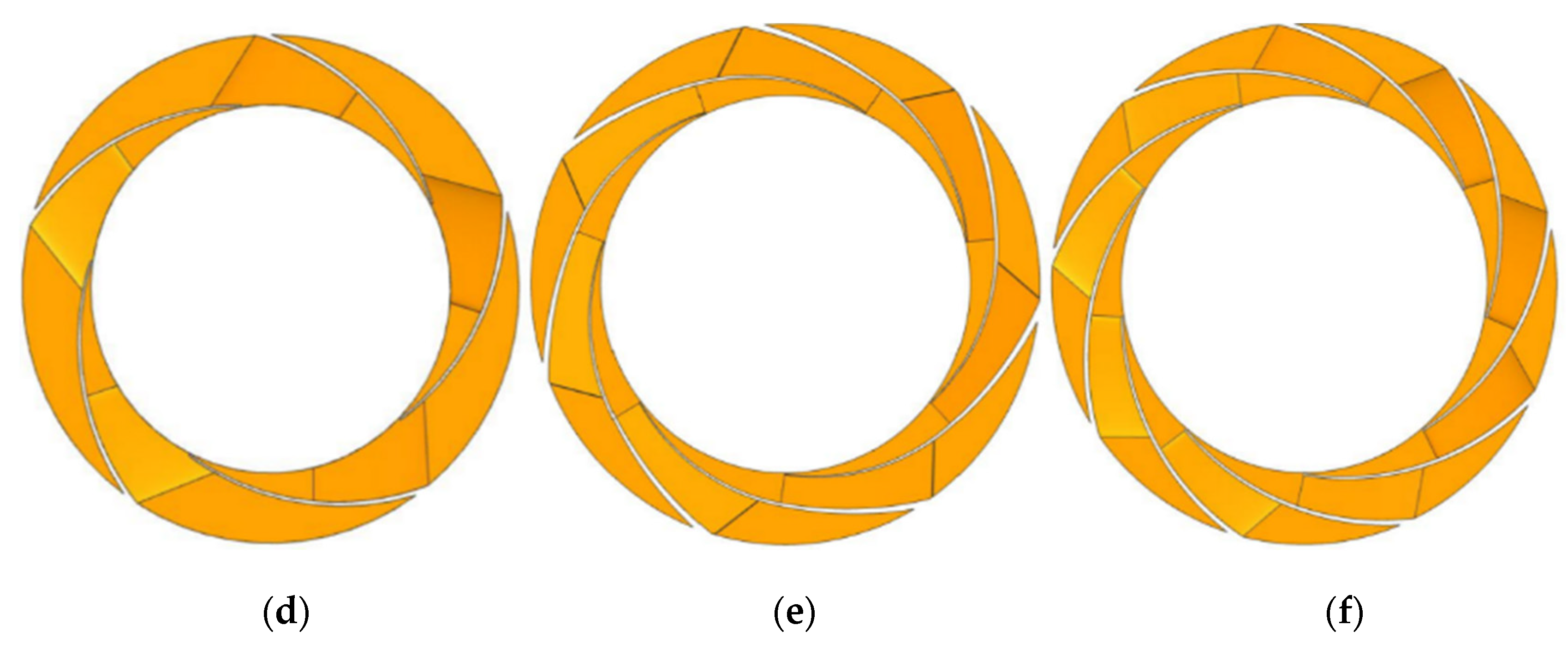
3.2.1. Scheme Design

The number of blades is an important geometric parameter for the impeller and guide vane. To determine the influence law of the number of impellers and guide vanes on the pump performance, according to the above optimal blade outlet width scheme, three impellers with six, seven, and eight blades and three guide vanes with five, seven, and nine blades are designed respectively, forming nine schemes. The three-dimensional modeling of impeller and guide vane is shown in Figure 13, and the scheme list is shown in Table 4.

3.2.2. The Number of Impeller Blades Remains Unchanged

Figure 14, Figure 15 and Figure 16 are the external characteristic curves obtained by changing the guide vanes blades to five, seven, and nine, while keeping the number of impeller blades six, seven, and eight unchanged, respectively. It shows that the performance of the pump is greatly different with different impeller and guide vane numbers. It has been noted that, when the number of impeller blades remains unchanged, the head of the pump changes greatly with the increase in the number of guide vanes from five to seven. The head at the small flow rate of 0.8Qdes increases sharply, and the head curve decreases rapidly with increasing flow rate. A hump appears in N2 and N6 schemes, which indicates that the number of blades is unreasonable, which is not conducive to the flow of liquid in the pump. However, the head of the nine-blade guide vane is between that of five blades and seven blades guide vane, which indicates that too many guide vanes increase the friction loss and decrease the head. Comparing the efficiency, it is found that the increased range of pump efficiency decreases with the increase in the number of guide vanes from seven to nine. The efficiency of nine blade guide vanes in each scheme is between five blades and seven blade guide vanes, which is completely consistent with the change law of head, indicating that an increase in guide vanes number is detrimental to the improvement of pump performance, but causes the reduction of head and efficiency. Compared with each scheme, when the flow rate is less than 1.3Qdes, whether in N2, N5 or N8 schemes, the scheme of seven-blade guide vane matched with any impeller with blade number, and the head and efficiency were significantly higher than other working conditions. It can be concluded that, no matter the number of impeller blades is six, seven, or eight, the guide vane with seven blades can have a good matching performance.

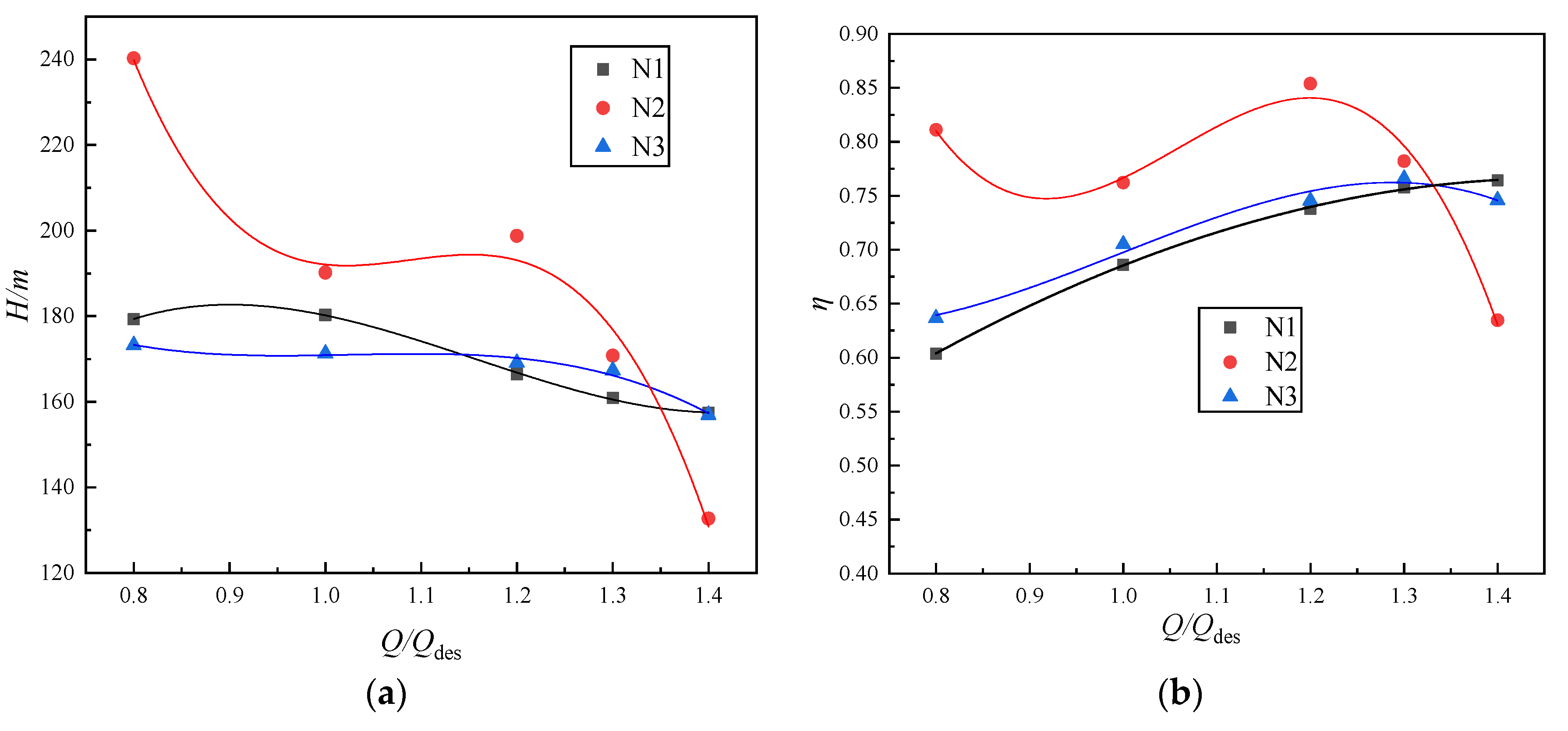
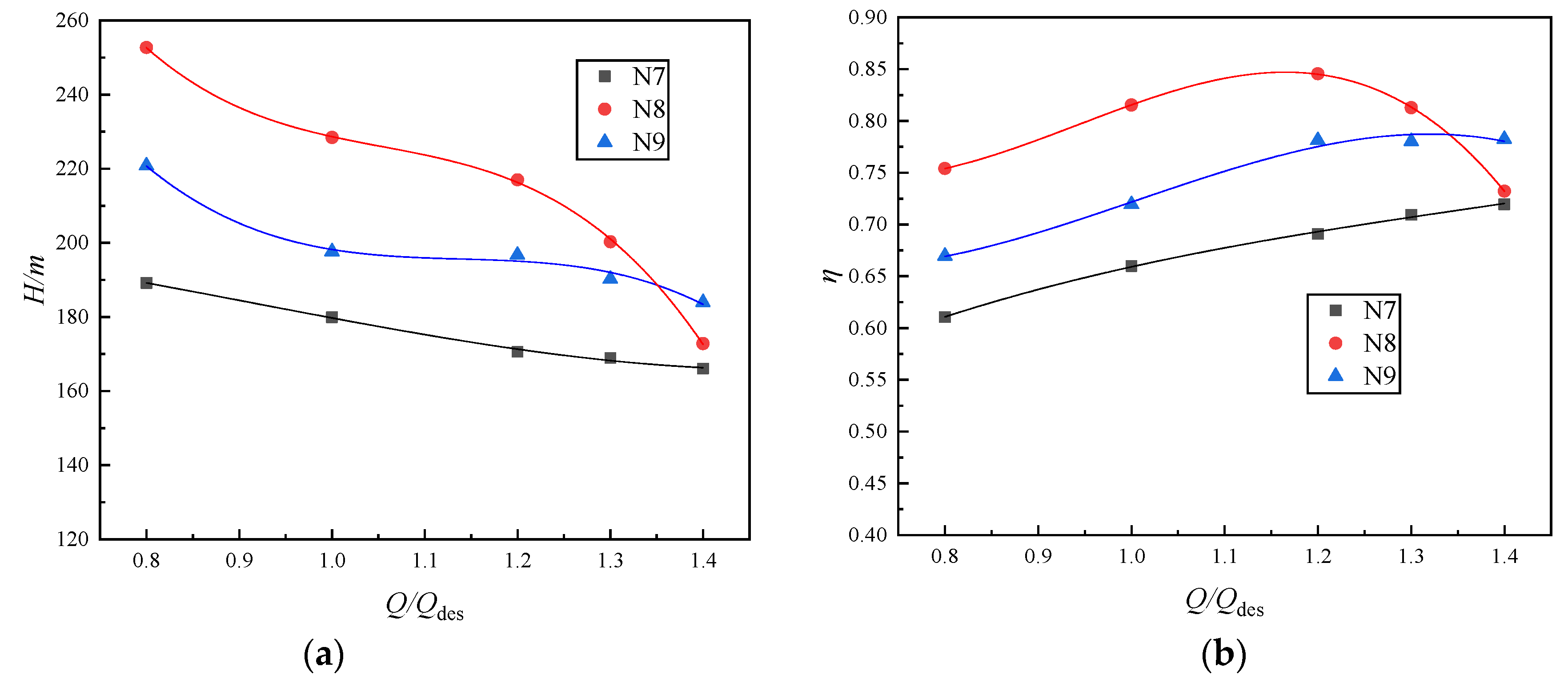
3.2.3. The Number of Guide Vanes Remains Unchanged

Figure 17, Figure 18 and Figure 19 are the external characteristic curves obtained by keeping the number of guide vanes five, seven, and nine unchanged, but changing the number of impeller blades to six, seven, and eight, respectively. Figure 17 shows that, when the number of guide vanes is kept at five, the head and efficiency of the pump change significantly with different impeller numbers. In large flow area, the head increases, and the efficiency decreases with the number of impeller blades increasing. This is due to the increase in the number of impeller blades, which increases the impeller’s ability to work on the fluid and improves the pump’s head. The excessive number of blades increases the blade friction loss, reduces the flow channel area, and reduces efficiency because of the shape of the guide vane inlet. As shown in Figure 18, for the scheme with guide vane number of seven, the increase in impeller blades number increases the pump head and effectively eliminates the hump of the pump head characteristic curve. With the increase in impeller blades number, compared with the scheme with six blades, the high-efficiency area of the scheme with seven and eight blades is significantly expanded, and the maximum efficiency of the impeller with eight blades is also improved. Figure 19 shows that when each impeller with nine guide vanes, the performance improvement of the pump is not evident. When the nine-blade guide vane is combined with the six-blade impeller, the overall head and efficiency are low, indicating that matching impeller outlet and guide vane inlet passage are unreasonable. When the nine-blade guide vane continues to match the seven-blade and eight-blade impellers, the head and efficiency are improved, and the high-efficiency area of efficiency is expanded. The maximum efficiency of the eight-blade impeller is also improved. However, the head of the seven-blade impeller appears to hump, and the head of the eight-blade impeller decreases rapidly at 0.8Qdes. In terms of efficiency, the efficiency of the eight-blade impeller scheme is slightly lower than that of the seven-blade impeller scheme before the 1.2Qdes condition. At a certain flow rate, efficiency is improved and slowly decreases with the increase in flow rate.

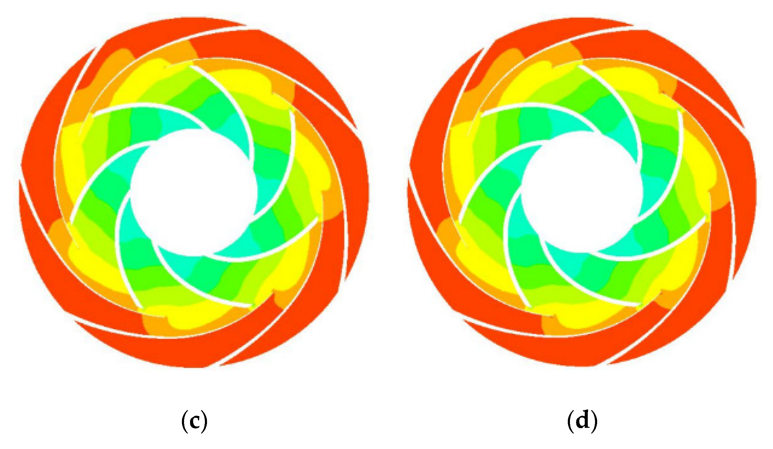
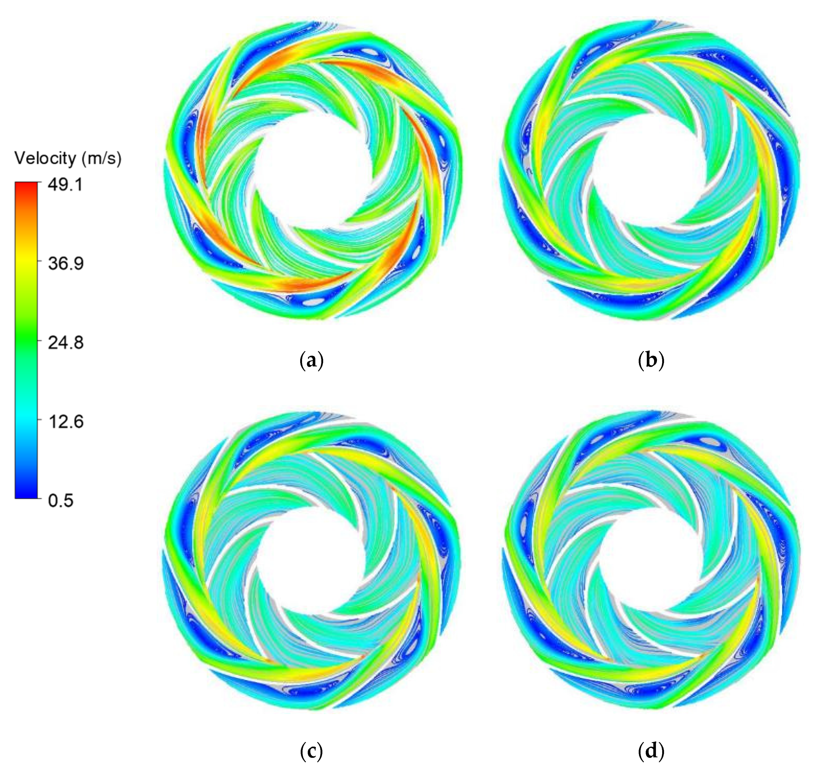
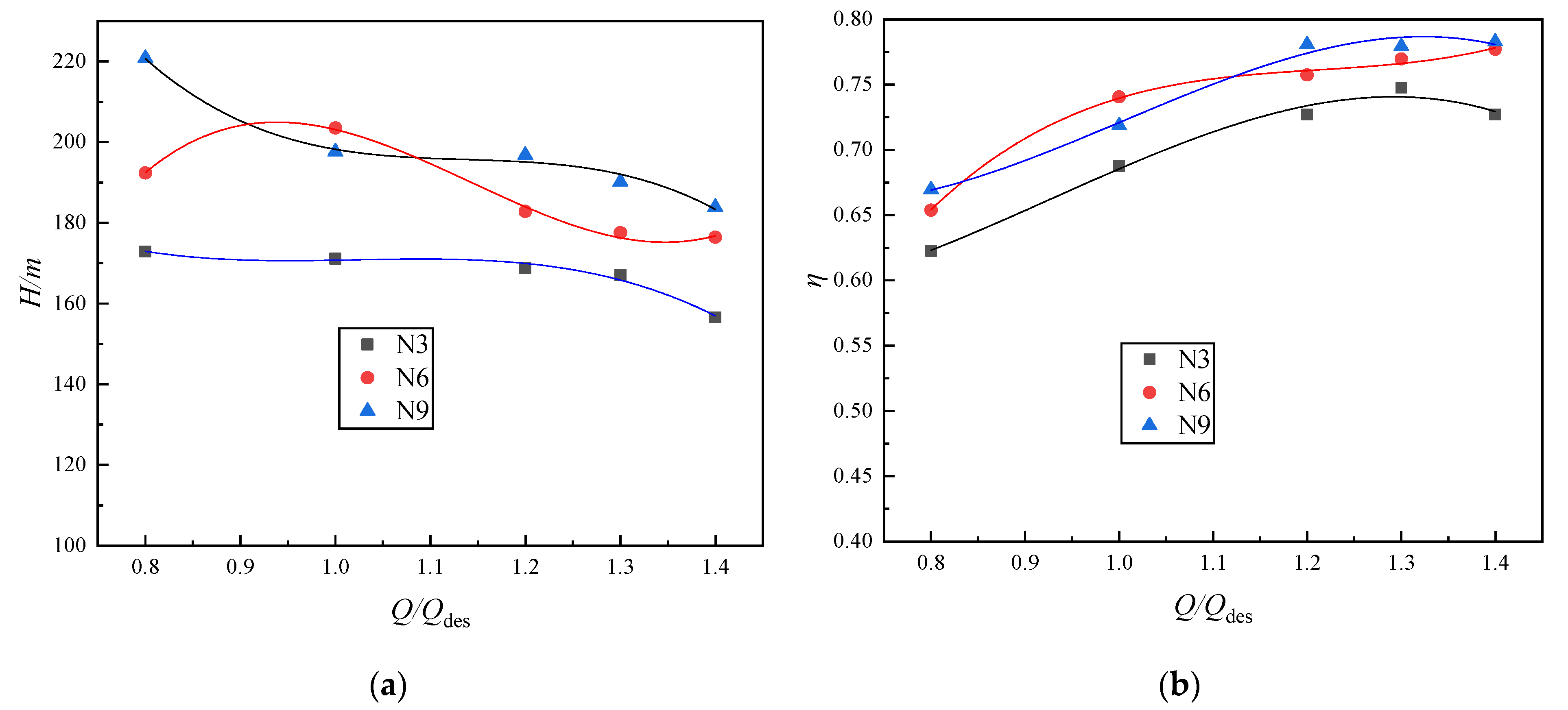
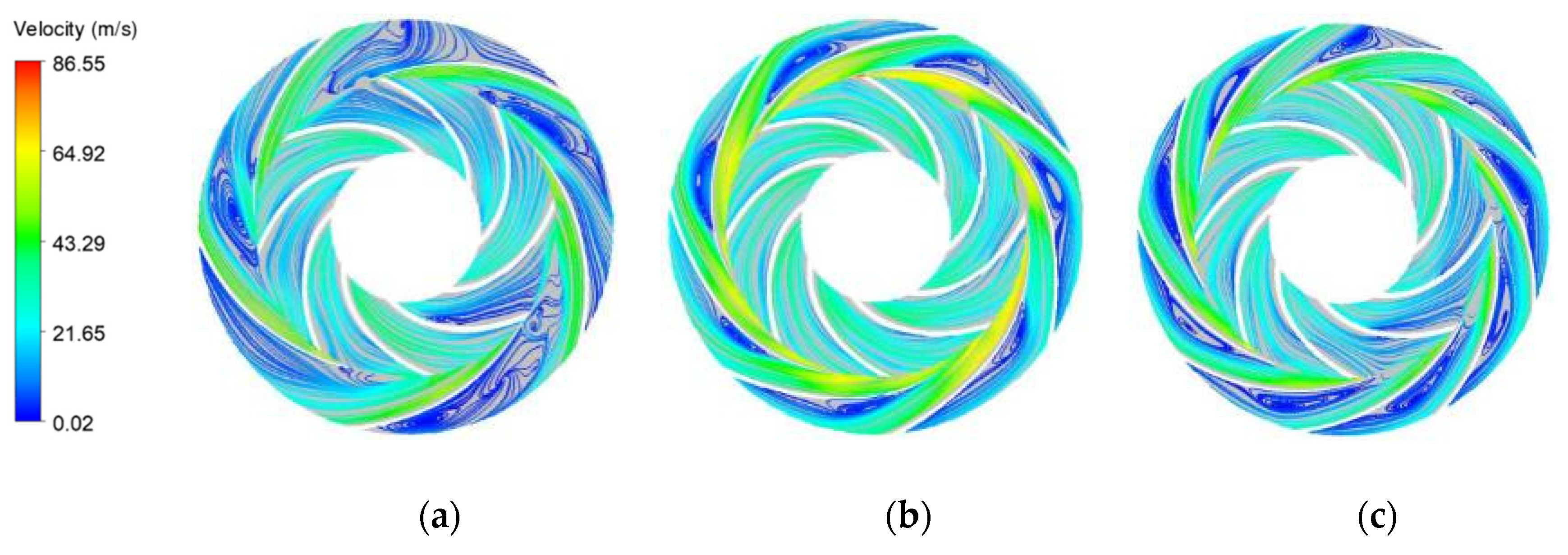
3.2.4. Analysis of Internal Flow Field

Figure 20 and Figure 21 respectively show the pressure distribution and streamline distribution cloud diagram of an eight-blade impeller with different guide vane blade numbers under 1.2Qdes conditions. Figure 20 shows that the pressure distribution of each scheme is significantly different by changing the number of guide vanes in turn while keeping the number of impeller blades unchanged at eight. The pressure distribution in the impeller of the five-blade guide vane scheme is relatively uniform. When the number of guide vanes increases from five to seven, the pressure in the impeller outlet area increases and the high-pressure area in the guide vane increases obviously, and the pressure in the guide vane is divided into two parts: the high-pressure area near the guide vane outlet and the low-pressure area at the guide vane inlet. When the number of guide vane blades increases to nine, the pressure in the guide vane decreases, and a local sporadic high-pressure area is formed at the outlet edge of the guide vane. The pressure distribution trend in the impeller and guide vane is consistent with the external characteristic results. The number of five blades and the outlet throat area of the guide vane is great, which cannot form a good match with the liquid flow from the impeller, resulting in low overall head and efficiency. The seven-blade guide vane can form a good match with the impeller, the pressure in the impeller and guide vane increases, and the head and efficiency are improved. The seven-blade guide vane increases the friction loss and reduces the overflow area, reducing head and efficiency.
Figure 21 presents that the number of guide vanes is different, and the biggest difference among the schemes is the connection of the transition flow field between the impeller and the guide vane and the flow field distribution in the guide vane. When the number of guide vanes is five, the flow lines at the guide vanes inlet and in the flow passage are irregular divergent. The flow in each flow passage of guide vanes is uneven and unstable. The low-speed region appears in some impeller flow passages, indicating that the matching and convergence performance of the impeller and guide vane flow field are poor, with the number of the impeller and guide vane being unreasonable. When the number of guide vanes increases to seven, the impeller and guide vane flow state improves. The flow velocity in the impeller increases and is uniform and stable, the low-speed zone disappears, the flow velocity in the guide vane presents an obvious stratification phenomenon, and some regular low-speed vortices appear in each channel of the guide vane. When the number of guide vanes continues to increase to nine, there is obvious velocity stratification in some single passages of the impeller. The velocity at the outlet of the impeller decreases, the high-speed region in the guide vane decreases, and the low-speed vortex increases, especially at the outlet of the guide vane passage. Comparing the schemes of eight-blade impeller matching different guide vane blade numbers, it is concluded that a reasonable combination of impeller and guide vane blade numbers can improve the flow state of liquid flow in the impeller and guide vane and make the flow tend to be stable. The internal flow state of the eight-blade impeller with a seven-blade guide vane is the best.
Figure 22 and Figure 23 respectively show the pressure distribution and streamline distribution cloud diagram under 1.2Qdes conditions for the scheme in which a seven-blade guide vane matches with different impeller blade numbers. Figure 22 shows that the pressure is low at the impeller inlet and increases gradually from the impeller inlet to the outlet along the blade flow direction. Uneven pressure diffusion occurs at the impeller outlet and guide vane inlet, the pressure in the guide vane is stratified, and the pressure at the guide vane outlet is high. Figure 23 shows that, as the number of impeller blades increases, the variation law of flow velocity in the impeller passage is relatively consistent, and the distribution of vortex area in the guide vane passage is slightly different. Generally, with the increase in the number of impeller blades, the low-speed vortex in the guide vane passage shows a decreasing trend. The low-speed vortex decrease indicates the flow state improvement, which creates an opportunity to improve the pump performance. From the external characteristic curve, the overall head and efficiency of the three schemes are higher. The head presents a slightly increasing trend, which indicates that the pump head can be improved by appropriately increasing the number of impeller blades when the number of guide vanes remains unchanged. Comparing the three schemes indicates that a good matching relationship between the guide vane with seven blades and the impeller with different blade numbers, which is consistent with the conclusion of external characteristics.
N5 (seven-blade impeller and seven-blade guide vane) and N8 (eight-blade impeller and seven-blade guide vane) have the best hydraulic performance compared to the other schemes. Considering that the number of impeller and guide vane should be reciprocal to avoid the resonance phenomenon in motion, N8 (eight-blade impeller and seven-blade guide vane) is selected as the best scheme.

3.3. Influence of Area Ratio of Impeller Outlet and Guide Vane Inlet

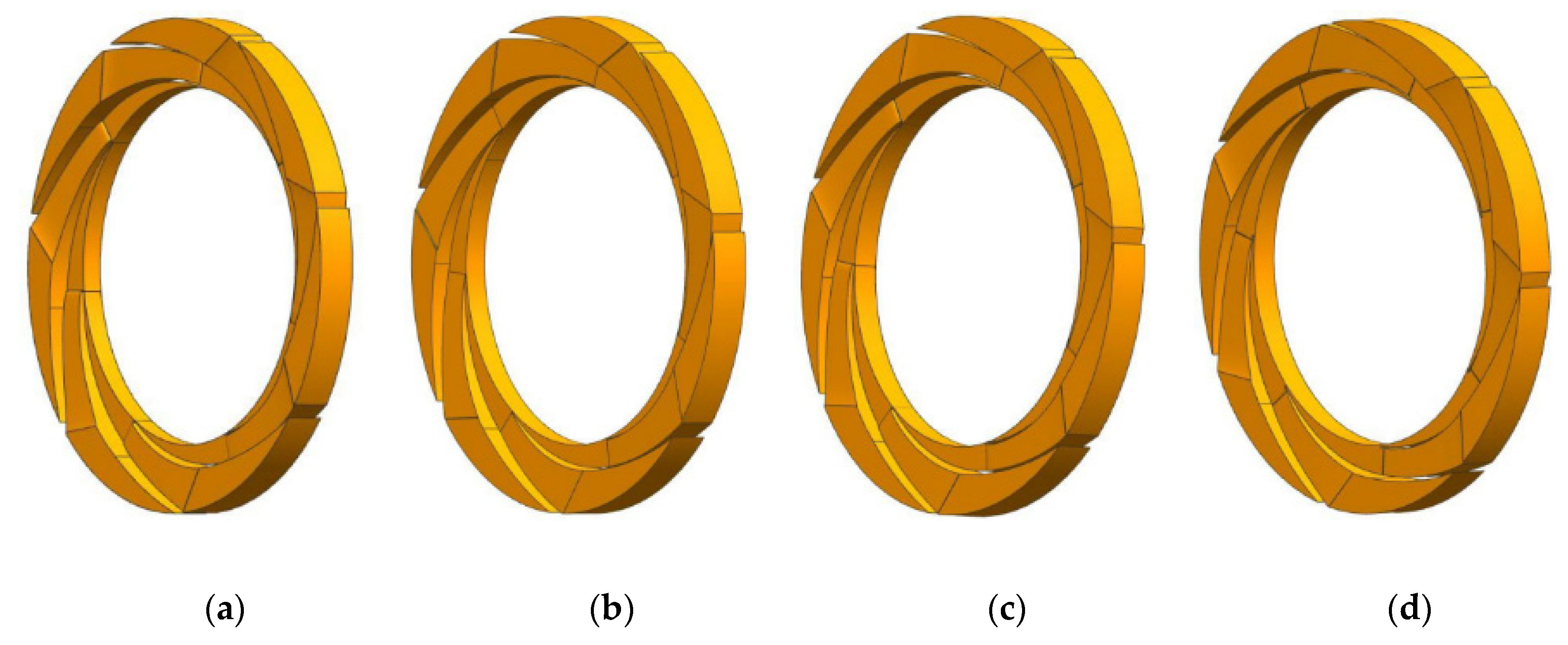
3.3.1. Scheme Design

The area ratio principle of centrifugal pump proposed by Anderson of Britain in 1938 pointed out that the ratio of impeller outlet flow area to pump throat area is the main factor affecting pump performance. It was found that the area ratio principle is not only applicable to volute centrifugal pumps, but also applicable to the segmental pump. Therefore, the area ratio principle is used to study the matching characteristics of the impeller and guide vane in this Section.
For the radial guide vane centrifugal pump, the calculation formula of throat area of radial guide vane is as follows:
F d = Z a 3 b 3
The calculation formula of impeller outlet area can be expressed as:
F 2 = π D 2 b 2 s i n β 2 × 0.95
Therefore, the area ratio formula of radial guide vane centrifugal pump is as follows:
Y d = F 2 F d = π D 2 b 2 s i n β 2 × 0.95 Z a 3 b 3
According to the formula, the three parameters affecting the throat area of the guide vane are the number of positive guide vane Z, the plane width a 3 of the inlet throat of the guide vane, and the outlet width b3 of the inlet throat of the guide vane. The relationship between the three is as follows:
Z d = π s i n 2 a 3 l n [ ( a 3 + δ 3 ) cos a 3 R 3 + 1 ]
S = a 3 b 3 = Q Z d v 3
where S is the throat area of the guide vane single channel.
In general, the determination of Zd requires that the wet circumference of the throat is as small as possible to make the section of the channel close to the square, that is, that the width of the guide vane inlet b3 and the width of the throat plane a 3 are equal or similar.
Keeping the impeller parameters unchanged, by changing the value of a 3 and b3 to change the area of the guide vane throat, four groups of guide vanes were designed using the difference method, recorded as guide vane 1 to guide vane 4. They are respectively matched with the impeller with eight blades selected in the upper section, and four groups of schemes are obtained, recorded as M1–M4 respectively, as shown in Table 5. The 3D modeling of the guide vane is shown in Figure 24.

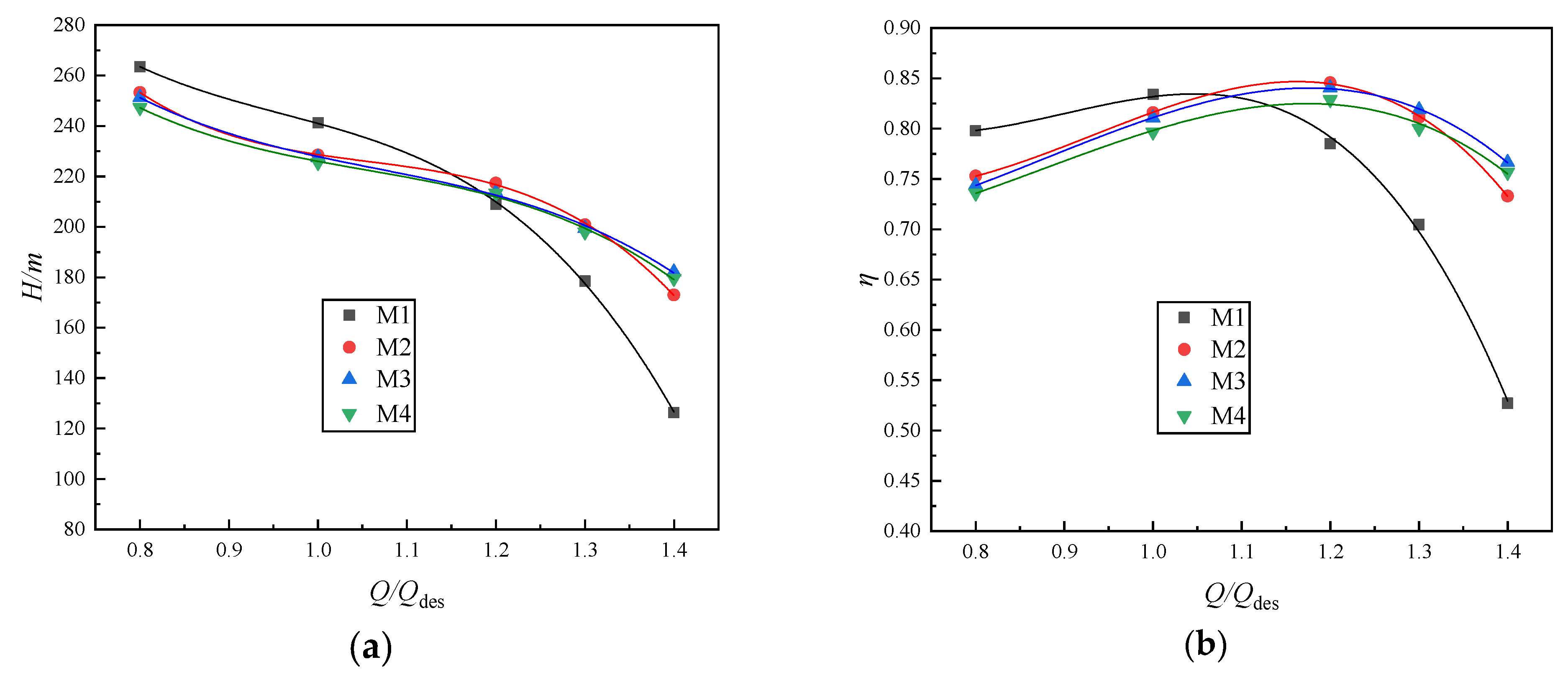
3.3.2. Analysis of External Characteristic Results

Figure 25 shows the external characteristic curves of the four different throat area schemes. From the changing trend of M1 to M4, it shows that, with the increase in the guide vane throat area, the pump head and efficiency show opposite changes law at large flow and small flow. In the large flow area, with the increase in throat area, the head and efficiency of the pump show an increasing trend, H M 3 > H M 4 > H M 2 > H M 1 , η M 3 > η M 4 > η M 2 > η M 1 . The head and efficiency of M3 are higher than that of M4, indicating that the larger throat area of the M4 scheme does not promote the continuous improvement of pump performance, and the throat area of the guide vane also has an optimal value. However, in the small flow, the changing trend is just the opposite, H M 4 < H M 3 < H M 2 < H M 1 , η M 4 < η M 3 < η M 2 < η M 1 . With the increase in the throat area of the guide vane, the efficiency of each scheme in the large flow area is significantly improved, the high-efficiency area becomes wider, and the highest efficiency point moves to the right and increases.
As shown from Figure 25, with the increase in the guide vane throat area, the decline in head and efficiency curve at large flow rate becomes slow. After 1.2Qdes, the head and efficiency of the M2, M3, and M4 schemes are significantly improved compared with the M1 scheme. At the same time, at a low flow rate of 0.8Qdes, the increase in guide vane throat area leads to a decrease in the head and efficiency of the M2, M3, and M4 schemes, which is unacceptable to the pump state in actual operation. A comprehensive comparison of each scheme shows that the M3 scheme has the best performance and efficient wide area, which can meet the requirements of the head and efficiency of the high-pressure pump. Next, the internal flow characteristics of different schemes under different conditions is studied, and the reasons for the performance differences of each scheme are analyzed.

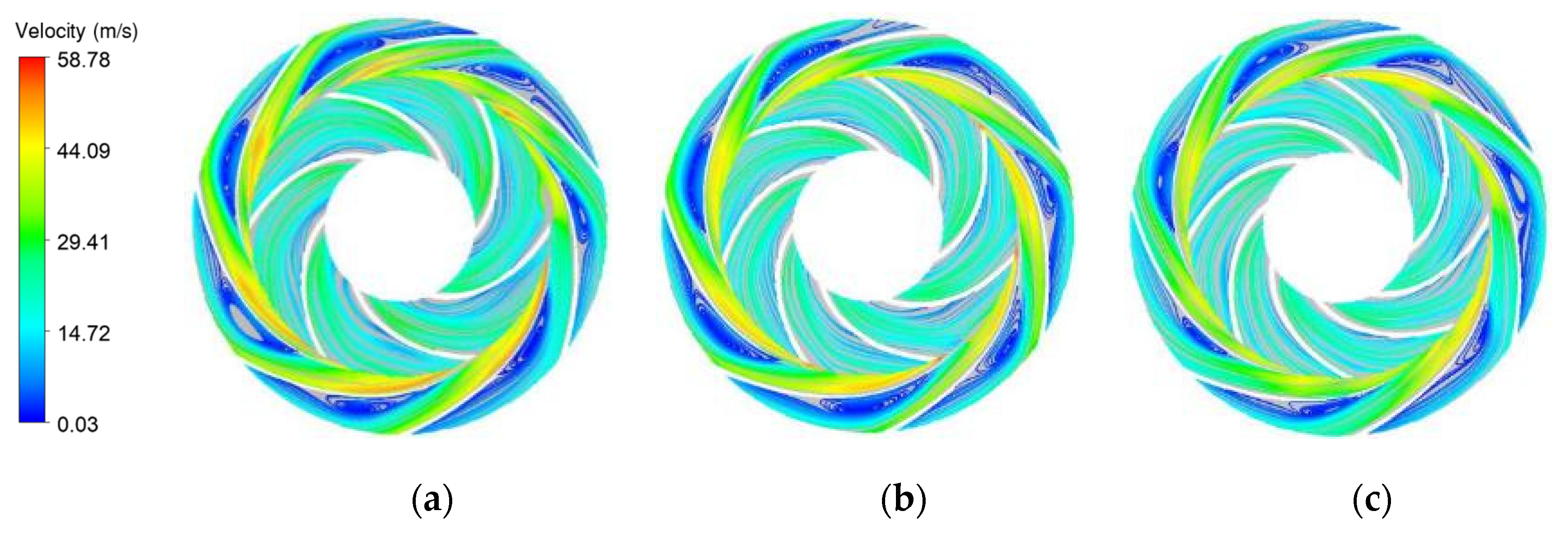
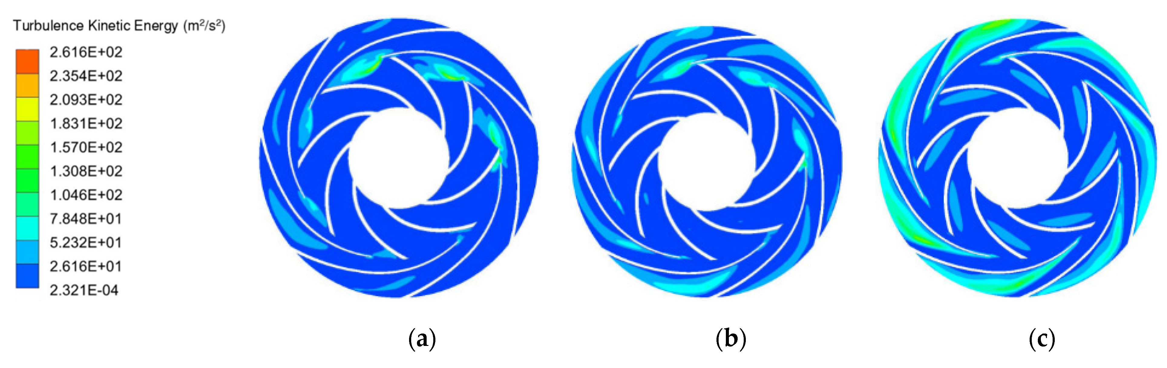
3.3.3. Analysis of Internal Flow Field

The external characteristic curve Figure 25 shows that the changing trend of the M2, M3, and M4 schemes is relatively consistent after the throat area of the guide vane is increased, and there is little difference in head efficiency, so the internal flow characteristics of M1 and M3 are only analyzed in this Section. Figure 26 and Figure 27 show the distribution cloud diagram of the turbulent kinetic energy of the M1 and the M3 schemes under different flow conditions. The magnitude of turbulent kinetic energy reflects the magnitude and range of fluctuating diffusion and viscous dissipation loss to a certain extent. The figure indicates that, at 0.8Qdes, the turbulent kinetic energy is larger, and the flow state is poor; with the flow rate increases to 1.0Qdes, the turbulent kinetic energy decreases, which indicates that the flow condition of 1.0Qdes was improved. When the flow rate continues to increase to 1.2Qdes, the turbulent kinetic energy in the outlet area of the guide vane increases obviously, which indicates that the fluid is undergoing intense energy exchange and the flow is very unstable. It can be seen from the distribution of turbulent kinetic energy under different flow conditions that the flow rate has a great influence on the turbulent kinetic energy. Under small flow conditions, the flow in the impeller is unstable, the liquid flow impact loss is great, and the turbulent kinetic energy is high, resulting in the low efficiency of the pump. Under large flow rate conditions, the increase in liquid flow velocity, impact loss, pulsation diffusion, and viscous dissipation also increase, and the efficiency of the pump decreases.
Compared with schemes M1 and M3, the turbulent kinetic energy under 0.8Qdes condition increases with the throat area of the guide vane, resulting in the low efficiency of scheme M3 at 0.8Qdes. As flow increases, the turbulent kinetic energy of the two schemes at 1.0Qdes decreases, and the efficiency increases. When the flow rate increases to 1.2Qdes, the turbulent kinetic energy of the M1 scheme is higher than that of the M3 scheme, and the corresponding external characteristic is that the efficiency of M1 decreases at 1.2Qdes and is lower than that of the M3 scheme. A comparative analysis shows that the throat area of guide vane has a significant influence on fluid flow. A too small throat area increases the impact loss and reduces the pump performance. Appropriately increasing the throat area can improve the liquid flow state, reduce the liquid flow impact loss and diffusion loss, expand the high-efficiency area of the pump, and move the highest efficiency point to the large flow area. Therefore, for the matching of impeller and guide vane, choosing an appropriate throat area can effectively improve the pump performance, which is extraordinarily significant in the hydraulic design.
This shows that a comprehensive consideration of the throat area of scheme M3 matches the impeller with the best hydraulic performance, which improves the head of the pump at a large flow and effectively widens the high-efficiency area at large flow and improves the pump performance.

4. Conclusions

In this study, the matching characteristics between different geometric parameters of impellers and guide vanes are considered. The matching characteristics of the impeller and guide vane of a large-scale seawater desalination high-pressure pump were studied regarding three aspects: outlet width of impeller blade, the impeller and guide vane blade number, and area ratio impeller outlet to guide vane inlet. The main conclusions are as follows:
  • The single-stage pump model is numerically calculated and processed into a solid pump for the experimental study. The results show that the numerical simulation results are in good agreement with the test results. Under 1.0Qdes condition, the error of numerical simulation and test head is 4.2%. Under 1.2Qdes condition, the error is 6.5%, which is within the allowable engineering range, indicating that the accuracy of numerical calculation is high;
  • Increasing the width of the blade outlet can improve the pump head and bring a certain improvement to the pump efficiency. In addition, there is an optimal value of the width of the blade outlet b2. When it exceeds this value, the performance of the pump declines. For this paper, the scheme of choosing the width of the blade outlet b2 = 28 mm effectively increased the pump head and improved the efficiency of the pump;
  • Under certain conditions, appropriately increasing the number of guide vane blades or changing the number of impeller blades can improve efficiency and expand the high-efficiency area. However, too many guide vane blades reduce the flow passage area and increase the diffusion loss, resulting in reduced head and efficiency. A comprehensive comparison shows that the eight-blade impeller with a seven-blade guide vane is well matched, with excellent hydraulic performance, high head, and efficient wide area;
  • The increase in the throat area of the guide vane has the opposite effect on the large flow and small flow area of the pump. In the small flow area, the head and efficiency of the pump decrease with the increase in throat area. In the large flow area, the pump’s performance is improved, the highest efficiency point moves to the right, and the high-efficiency area expands. Compared with each scheme, the M3 scheme is adopted, and the performance of the pump is the best, which meets the design requirements.

Author Contributions

Methodology, W.L.; validation, W.L., J.H. and X.Y.; formal analysis, M.L.; investigation, M.A.; data curation, L.J., Y.W.; writing—original draft preparation, M.L.; writing—review and editing, W.L., M.L.; project administration, W.L.; funding acquisition, W.L. All authors have read and agreed to the published version of the manuscript.

Funding

The work was sponsored by the Key International Cooperative research of National Natural Science Foundation of China (No. 52120105010), National Natural Science Foundation of China (No. 52179085), the National Key R&D Program Project (No. 2020YFC1512405), the Fifth “333 High Level Talented Person Cultivating Project” of Jiangsu Province, Funded projects of “Blue Project” in Jiangsu Colleges and Universities, “Belt and Road” Innovation Cooperation Project of Jiangsu Province (No. BZ2020068), Independent Innovation Fund Project of Agricultural Science and Technology in Jiangsu Province (No. CX(20)2037).

Institutional Review Board Statement

Not applicable.

Informed Consent Statement

Not applicable.

Data Availability Statement

Not applicable.

Acknowledgments

We would like to thank the anonymous reviewers and the editor for their valuable comments and remarks that helped us to improve the original manuscript.

Conflicts of Interest

The authors declare that they have no known competing financial interests or personal relationships that could have appeared to influence the work reported in this paper.

Nomenclature

DjImpeller inlet diameter, mm
D2Impeller outlet diameter, mm
DhImpeller hub diameter, mm
b2Blade outlet width, mm
β2Blade outlet angle, °
φBlade envelope angle, °
ZNumber of impeller blades
D3Diameter of positive guide blade base circle, mm
b3Axial inlet width of positive guide vane, mm
a3Inlet width of the positive guide vane plane, mm
b4axial outlet width of the positive guide vane, mm
a4Outlet width of the positive guide vane plane, mm
D4Outlet diameter of positive guide vane, mm
ZdNumber of positive guide vanes
HHead, m
ηEfficiency

References

  1. Javanbakht, A.; Ahmadi Danesh Ashtian, H. Impeller and volute design and optimization of the centrifugal pump with low specific speed in order to extract performance curves. J. Comput. Appl. Mech. 2018, 49, 359–366. [Google Scholar]
  2. Subroto; Effendy, M. Optimization of centrifugal pump performance with various blade number. In Proceedings of the AIP Conference Proceedings, 12–13 December 2018; AIP Publishing LLC: Melville, NY, USA; Volume 2114, p. 20016. [Google Scholar]
  3. Zhou, L.; Shi, W.; Wu, S. Performance optimization in a centrifugal pump impeller by orthogonal experiment and numerical simulation. Adv. Mech. Eng. 2013, 5, 385809. [Google Scholar] [CrossRef] [Green Version]
  4. Fracassi, A.; de Donno, R.; Ghidoni, A.; Congedo, P.M. Shape optimization and uncertainty assessment of a centrifugal pump. Eng. Optim. 2020, 1–18. Available online: https://www.tandfonline.com/doi/abs/10.1080/0305215X.2020.1858075 (accessed on 8 January 2022). [CrossRef]
  5. Li, W.; Zhao, X.; Li, W.; Shi, W.; Ji, L.; Zhou, L. Numerical prediction and Performance experiment in an engine cooling water pump with different blade outlet widths. Math. Probl. Eng. 2017, 2017, 8945712. [Google Scholar] [CrossRef] [Green Version]
  6. Li, W.; Jiang, X.; Pang, Q.; Zhou, L.; Wang, W. Numerical simulation and performance analysis of a four-stage centrifugal pump. Adv. Mech. Eng. 2016, 8, 1687814016673756. [Google Scholar] [CrossRef] [Green Version]
  7. Li, W.; Zhang, Y.; Shi, W.; Ji, L.; Yang, Y.; Ping, Y. Numerical simulation of transient flow field in a mixed-flow pump during starting period. Int. J. Numer. Methods Heat Fluid Flow 2018, 28, 927–942. [Google Scholar] [CrossRef]
  8. Zhao, R.-J.; Zhao, Y.-L.; Zhang, D.-S.; Li, Y.; Geng, L.-L. Numerical Investigation of the Characteristics of Erosion in a Centrifugal Pump for Transporting Dilute Particle-Laden Flows. J. Mar. Sci. Eng. 2021, 9, 961. [Google Scholar] [CrossRef]
  9. Song, X.; Yao, R.; Shen, Y.; Bi, H.; Zhang, Y.; Du, L.; Wang, Z. Numerical Prediction of Erosion Based on the Solid-Liquid Two-Phase Flow in a Double-Suction Centrifugal Pump. J. Mar. Sci. Eng. 2021, 9, 836. [Google Scholar] [CrossRef]
  10. Ji, L.; Li, W.; Shi, W.; Agarwal, R.K. Application of Wray–Agarwal Turbulence Model in Flow Simulation of a Centrifugal Pump with Semispiral Suction Chamber. J. Fluids Eng. 2021, 143, 31203. [Google Scholar] [CrossRef]
  11. Shojaeefard, M.H.; Tahani, M.; Khalkhali, A.; Ehghaghi, M.B.; Fallah, H.; Beglari, M. A parametric study for improving the centrifugal pump impeller for use in viscous fluid pumping. Heat Mass Transf. 2013, 49, 197–206. [Google Scholar] [CrossRef]
  12. Wu, X.; Feng, J.; Liu, H.; Ding, J.; Chen, H. Performance prediction of single-channel centrifugal pump with steady and unsteady calculation and working condition adaptability for turbulence model. Trans. Chin. Soc. Agric. Eng. 2017, 33, 85–91. [Google Scholar]
  13. Guo, J.-P.; Gao, Z.-X.; Qin, D.-Q.; Xing, H.-X. Hydraulic design optimization of centrifugal pump with high head and large capacity by using CFD. J. Drain. Irrig. Mach. Eng. 2013, 31, 220–224. [Google Scholar]
  14. Mojaddam, M.; Namazizadeh, M.; Talebian Gevari, M.; Vajdi, M. Optimization of the splitter blade configuration and geometry of a centrifugal pump impeller using design of experiment. J. Appl. Fluid Mech. 2019, 13, 89–101. [Google Scholar]
  15. Fu, D.-C.; Wang, F.-J.; Zhou, P.-J.; Xiao, R.-F.; Yao, Z.-F. Impact of impeller stagger angles on pressure fluctuation for a double-suction centrifugal pump. Chin. J. Mech. Eng. 2018, 31, 1–14. [Google Scholar] [CrossRef] [Green Version]
  16. Alemi, H.; Nourbakhsh, S.A.; Raisee, M.; Najafi, A.F. Effects of volute curvature on performance of a low specific-speed centrifugal pump at design and off-design conditions. J. Turbomach. 2015, 137, 41009. [Google Scholar] [CrossRef]
  17. Nataraj, M.; Ragoth Singh, R. Analyzing pump impeller for performance evaluation using RSM and CFD. Desalin. Water Treat. 2014, 52, 6822–6831. [Google Scholar] [CrossRef]
  18. Jafarzadeh, B.; Hajari, A.; Alishahi, M.M.; Akbari, M.H. The flow simulation of a low-specific-speed high-speed centrifugal pump. Appl. Math. Model. 2011, 35, 242–249. [Google Scholar] [CrossRef]
  19. Bellary, S.A.I.; Samad, A. Improvement of efficiency by design optimization of a centrifugal pump impeller. In Proceedings of the Turbo Expo: Power for Land, Sea, and Air, 16–20 June; American Society of Mechanical Engineers: New York, NY, USA; Volume 45639, p. V02DT42A007.
  20. Tan, M.; Guo, B.; Liu, H.; Wu, X.; Wang, K. Investigation of radial force and hydraulic performance in a centrifugal pump with different guide vane outlet angle. J. Vibroengineering 2015, 17, 3247–3260. [Google Scholar]
  21. Li, W.; Ji, L.; Shi, W.; Zhou, L.; Chang, H.; Agarwal, R.K. Expansion of high efficiency region of wind energy centrifugal pump based on factorial experiment design and computational fluid dynamics. Energies 2020, 13, 483. [Google Scholar] [CrossRef] [Green Version]
  22. Qi, F.-L.; Liu, G.-C.; Horia, A.; Wang, Y.-Z. Influence of different impellers on the flow field in the centrifugal pump. Chin. J. Constr. Mach. 2018, 5, 382–388. [Google Scholar]
  23. Wang, J.-Q.; Kong, F.-Y. Hydraulic performance optimization study on impeller and diffuser of multi-stage centrifugal pump. J. Huazhong Univ. Sci. Technol. Nat. Sci. Ed. 2013, 3, 92–96. [Google Scholar]
  24. Kong, F.-Y.; Su, X.-H.; Chen, H.; Qu, X.-Y.; Jiang, W.-M. Optimal design on parameters of guide vane of radial diffusers in centrifugal pump. Trans. Chin. Soc. Agric. Eng. 2013, 28, 40–45. [Google Scholar]
  25. Kaya, D. Experimental study on regaining the tangential velocity energy of axial flow pump. Energy Convers. Manag. 2003, 44, 1817–1829. [Google Scholar] [CrossRef]
  26. Tsukamoto, H.; Uno, M.; Qin, W.; Teshima, T.; Sakamoto, K.; Okamura, T. Unsteady hydraulic force on an impeller due to rotor-stator interaction in a diffuser pump. In Hydraulic Machinery and Cavitation; Springer: Berlin, Germany, 1996; pp. 955–964. [Google Scholar]
  27. Wang, Y.; Li, W.; Hu, J.; Ye, X.; Geng, H.; Wang, X. Optimization design of hydraulic components of high-pressure pump for ten thousand-ton-scale seawater desalination installations. J. Drain. Irrig. Mach. Eng. 2020, 1, 30–36. [Google Scholar]
  28. Hu, J.-N.; Jiang, W.; Liu, S.-H.; Xu, W.-G. Influence of Various Turbulent Flow Models on the Precision of Simulating a Seawater Desalination-purpose Lift Pump. J. Eng. Therm. Energy Power 2011, 26, 483–486. [Google Scholar]
  29. Chang, H.; Li, W.; Shi, W.; Liu, J. Effect of blade profile with different thickness distribution on the pressure characteristics of novel self-priming pump. J. Braz. Soc. Mech. Sci. Eng. 2018, 40, 1–20. [Google Scholar] [CrossRef]
  30. Sun, J.; Wang, Y.; Xu, S.; Wang, S.; Wang, Y. Performance prediction of hydraulic energy recovery (HER) device with novel mechanics for small-scale SWRO desalination system. Desalination 2009, 249, 667–671. [Google Scholar] [CrossRef]
  31. Launder, B.E.; Spalding, D.B. Lectures in Mathematical Models of Turbulence; Academic Press: London, UK, 1972. [Google Scholar]
Figure 1. Structure diagram of single-stage pump model.
Jmse 10 00115 g001
Figure 2. Three-dimensional modeling of main overflow components. (a) Guide vane entity, (b) Guide vane water body, (c) Impeller entity, (d) Impeller water body.
Jmse 10 00115 g002
Figure 3. Fluid computing domain of single-stage model pump.
Jmse 10 00115 g003
Figure 4. Meshing of main flow through components. (a) Impeller, (b) Guide vane, (c) Front pump chamber, (d) Rear pump chamber, (e) Outlet section.
Jmse 10 00115 g004
Figure 5. Assembly meshing in the fluid computing domain.
Jmse 10 00115 g005
Figure 6. Schematic diagram of the test bench.
Jmse 10 00115 g006
Figure 7. Model pump installation illustration.
Jmse 10 00115 g007
Figure 8. Comparison of external characteristics of numerical simulation and test.
Jmse 10 00115 g008
Figure 9. Four groups of impellers with different blade outlet widths. (a) b2 = 24 mm, (b) b2 = 26 mm, (c) b2 = 28 mm, (d) b2 = 30 mm.
Jmse 10 00115 g009
Figure 10. External characteristic curve of different blade outlet widths. (a) Q-H, (b) Q-η.
Jmse 10 00115 g010
Figure 11. Pressure distribution of impeller and guide vane with different b2 value. (a) b2 = 24 mm, (b) b2 = 26 mm, (c) b2 = 28 mm, (d) b2 = 30 mm.
Jmse 10 00115 g011aJmse 10 00115 g011b
Figure 12. Velocity distribution of impellers and guide vanes with different b2 values. (a) b2 = 24 mm, (b) b2 = 26 mm, (c) b2 = 28 mm, (d) b2 = 30 mm.
Jmse 10 00115 g012
Figure 13. Three-dimensional modeling of impeller and guide vane. (a) 6-blade impeller, (b) 7-blade impeller, (c) 8-blade impeller, (d) 5-blade guide vane, (e) 7-blade guide vane, (f) 9-blade guide vane.
Jmse 10 00115 g013aJmse 10 00115 g013b
Figure 14. Characteristic curves of various schemes when the impeller blade number is 6. (a) Q-H, (b) Q-η.
Jmse 10 00115 g014
Figure 15. Characteristic curves of various schemes when the impeller blade number is 7. (a) Q-H, (b) Q-η.
Jmse 10 00115 g015
Figure 16. Characteristic curves of various schemes when the impeller blade number is 8. (a) Q-H, (b) Q-η.
Jmse 10 00115 g016
Figure 17. Characteristic curves of different schemes when the guide vane number is 5. (a) Q-H, (b) Q-η.
Jmse 10 00115 g017
Figure 18. Characteristic curves of different schemes when the guide vane number is 7. (a) Q-H, (b) Q-η.
Jmse 10 00115 g018
Figure 19. Characteristic curves of different schemes when the guide vane number is 9. (a) Q-H, (b) Q-η.
Jmse 10 00115 g019
Figure 20. Pressure distribution of different guide vane schemes under the 8-blade impeller. (a) 5-blade guide vane, (b) 7-blade guide vane, (c) 9-blade guide vane.
Jmse 10 00115 g020
Figure 21. Velocity distribution of different guide vane schemes under the 8-blade impeller. (a) 5-blade impeller, (b) 7-blade impeller, (c) 9-blade impeller.
Jmse 10 00115 g021
Figure 22. Pressure distribution of different impeller blade numbers under the 7-blade guide vane. (a) 6-blade impeller, (b) 7-blade impeller, (c) 8-blade impeller.
Jmse 10 00115 g022
Figure 23. Velocity distribution of different impeller blade numbers under the 7-blade guide vane. (a) 6-blade impeller, (b) 7-blade impeller, (c) 8-blade impeller.
Jmse 10 00115 g023
Figure 24. Three-dimensional modeling of the four guide vanes. (a) Guide vane 1, (b) Guide vane 2, (c) Guide vane 3, (d) Guide vane 4.
Jmse 10 00115 g024
Figure 25. External characteristic curve of the different throat area schemes. (a) Q-H, (b) Q-η.
Jmse 10 00115 g025
Figure 26. Turbulence kinetic energy distribution of M1 scheme under different flow conditions. (a) 0.8Qdes, (b) 1.0Qdes, (c) 1.2Qdes.
Jmse 10 00115 g026
Figure 27. Turbulence kinetic energy distribution of M3 scheme under different flow conditions. (a) 0.8Qdes, (b) 1.0Qdes, (c) 1.2Qdes.
Jmse 10 00115 g027
Table 1. Main geometric parameters of the impeller and guide vane.
SymbolImpellerSymbolGuide Vane
Dj222 mmD3402 mm
Dh139 mmb333 mm
b227 mma325.8 mm
D2400 mmb443.6 mm
β225°a438.4 mm
φ130°D4560 mm
Z6Zd9
Table 2. Calculation of head under different grid numbers.
SchemeTotal Number of GridsHead H (m)
12,755,852185.6
23,106,242202.3
33,625,141203.7
44,356,823202.8
Table 3. Blade outlet width scheme.
Scheme Number1234
b224 mm26 mm28 mm30 mm
Table 4. Scheme list.
SchemeNumber of Impeller BladesNumber of Guide Vanes
N165
N267
N369
N475
N577
N679
N785
N887
N989
Table 5. List of different guide vane throat area schemes.
SchemeGuide Vanea3/mmb3/mmFd/mmYd
M11293060902.319
M22293366992.108
M33293673081.932
M44343685681.648
Publisher’s Note: MDPI stays neutral with regard to jurisdictional claims in published maps and institutional affiliations.

