Article

Design and Experiment of a Universal Harvesting Platform for Cabbage and Chinese Cabbage

1
School of Agricultural Engineering, Jiangsu University, Zhenjiang 212013, China
2
Key Laboratory of Modern Agricultural Equipment and Technology, Ministry of Education, Jiangsu University, Zhenjiang 212013, China
*
Author to whom correspondence should be addressed.
Agriculture 2025, 15(9), 935; https://doi.org/10.3390/agriculture15090935
Submission received: 2 April 2025 / Revised: 18 April 2025 / Accepted: 23 April 2025 / Published: 25 April 2025
(This article belongs to the Section Agricultural Technology)

Abstract

:
To address the issue of the single-crop adaptability of current head-forming leafy vegetable harvesters in China—which limits their ability to harvest multiple vegetable varieties—a universal cabbage–Chinese cabbage harvesting platform was designed. This design was based on the statistical analysis of the physical and planting parameters of major cabbage and Chinese cabbage varieties in Jiangsu and Zhejiang provinces. The harvesting platform adopts a modular design, enabling the harvesting of both Chinese cabbage and cabbage by replacing specific components and adjusting relevant parameters. Through the theoretical analysis of key components, the specific parameters of each part were determined, and a soil-trough harvesting test was conducted. The results of the Chinese cabbage harvesting test showed that at a forward speed of 1 km·h−1 and a conveyor belt speed of 60 RPM, the platform achieved optimal performance, with an extraction success rate of 86.7%, a clamping and conveying success rate of 92.3%, and an operational damage rate of 6.7%. The cabbage soil-trough harvesting test results indicated that when the extraction roller speed was 100 RPM, the conveyor belt speed was 60 RPM, and the forward speed was 1 km·h−1, the extraction and feeding success rate reached 93.3%, the conveying success rate was 100%, and the operational loss rate was 6.7%, representing the best overall performance. This study provides theoretical support and references for the design of universal harvesters for head-forming leafy vegetables.

1. Introduction

Head-forming leafy vegetables mainly include cabbage, lettuce, broccoli, Chinese cabbage, and other vegetables that are harvested by cutting off the roots at the soil surface [1]. China is the world’s largest producer and consumer of vegetables, with the vegetable planting area accounting for about 40% of the global total and yield about 50% [2]. At present, cabbage harvesting machinery in China is relatively mature, with numerous machines designed and commercialized. In contrast, Chinese cabbage has a higher water content and its leaves are more prone to damage. Currently, research on Chinese cabbage harvesters in China is limited and the harvesting performance is generally mediocre. Moreover, the design of harvest machinery for head-forming leafy vegetables such as cabbage and Chinese cabbage is often tailored for a single type of vegetable, resulting in high unit prices and limited popularization.
Research on cabbage harvesters began earlier abroad. Hansen et al. employed a dual-helical lifting device to accomplish the extraction and conveying of cabbage [3], while Lenker used a pair of conveyor belts to complete the clamping and conveying operations for cabbage [4]. In recent years, companies such as Hortech, Asa-lift, and Univerco have marketed commercial machines [5]; however, these models either require large tractors for towing or are themselves very large and expensive, and they can only harvest a single variety of cabbage. There has also been considerable research on cabbage harvesters in China. The Nanjing Agricultural Mechanization Research Institute designed a double-row cabbage harvester that uses extraction rollers for extraction, a pair of conveyor belts for clamping and conveying, and performs root-cutting during the clamping and conveying process [6]. In addition, Jiangsu University designed a pure electric, side-suspended cabbage harvester for tractors [7]. Currently, mainstream domestic cabbage harvesters generally use extraction rollers combined with a leaf-stripping wheel to pull out and feed the cabbage. A pair of symmetrically arranged conveyor belts clamp and convey the cabbage rearward, while simultaneously performing the root-cutting operation during the clamping process.
The main cultivation areas for Chinese cabbage globally are China, Japan, South Korea, and Southeast Asia. South Korea and Japan have conducted significant research on cabbage harvester equipment and related technologies. In 1996, Kanamitsu from the Planning Department of the Japan Agricultural Machinery Research Institute designed a side-suspended cabbage harvester for tractors [8]. This harvester first uses a pair of double-axis spiral rollers to pull out the cabbage, and then a pair of synchronous belts clamp and convey the cabbage rearward. During the clamping and conveying process, the top of the double-axis spiral rollers is used as a reference plane. When the size of the cabbage varies, the top of the double-axis spiral rollers serves as a limit, reducing deviations in the optimal cutting position caused by inconsistent cabbage sizes. Experimental results showed that the harvester performed satisfactorily when the cabbage diameter was medium, although the performance decreased significantly when the diameter deviation was too large. Kim et al. from Chonnam National University in South Korea designed a self-propelled cabbage harvester, which uses a pair of conveyor belts to directly clamp the cabbage and complete the extraction operation [9]. The experimental results showed a 20% slippage rate during the extraction process. Yang et al. from Kyungpook National University in South Korea compared a plate-type extraction device with a double-spiral extraction device [10]. The experimental results indicated that the soil attached to the plate-type extraction device was difficult to remove. Using the double-spiral extraction device, the experimental results showed that when the cutter height was set to 5 mm, the cutting success rate was only 11.4%, with 74.1% of the cabbages not being effectively cut. There is relatively limited and lower-level research on Chinese cabbage harvesters in China. Zhang, J. et al. from Zhejiang University designed a crawler self-propelled single-row Chinese cabbage harvester, which employs a mechanized harvesting method that first cuts the roots and then clamps and conveys the cabbage [11]. During operation, a pair of contour-following cutters close to the ground complete the harvest. Field test results showed an average operational loss rate of 7.84%, which basically meets the requirements for the mechanized harvesting of Chinese cabbage. Currently, there are two main harvesting approaches for Chinese cabbage: root-cutting followed by conveying and extraction followed by root-cutting. The drawback of the root-cutting-first approach is that the contour-following cutter has poor cutting performance when faced with uneven ridges or Chinese cabbage with varying root lengths. The advantage of the extraction-first approach is that subsequent devices can address the issue of determining the optimal root-cutting position. However, the extraction device is difficult to design and has poor reliability.
From the analysis above, it is evident that cabbage harvesting machines are relatively mature in China, while research on Chinese cabbage harvesters is less advanced. Moreover, these harvesting machines are typically designed to harvest only one type of vegetable, either cabbage or Chinese cabbage, and cannot handle multiple vegetable varieties. Therefore, to improve the universality of harvesting machinery and achieve multi-functional use, this paper focuses on the cabbage and Chinese cabbage varieties commonly grown in the southern Jiangsu and Zhejiang regions, one of China’s major vegetable-producing areas. By combining their agronomic practices and physical parameters, this study aims to identify common characteristics between the two crops and design a universal cabbage–Chinese cabbage harvesting platform. The platform, through a modular design, allows for the replacement of components and adjustment of parameters to achieve both extraction and clamping–conveying operations for cabbage and Chinese cabbage.

2. Universal Harvesting Strategy and Overall Scheme

2.1. Cabbage and Chinese Cabbage Varieties and Their Main Cultivation Patterns

2.1.1. Cabbage and Chinese Cabbage Varieties

To design the extraction and clamping–conveying devices effectively, it is necessary to understand the varieties of cabbage and Chinese cabbage, along with their respective physical parameters. Based on the measurements by Du, D.D. and others, as well as those conducted by the team, we have summarized the physical characteristics of five common cabbage varieties, including the “Aoqina” variety, as shown in Table 1 [12]. Similarly, referring to the measurements by Zhang Jing et al. and our own, we have summarized the physical characteristics of three common Chinese cabbage varieties, including the “Huangxin” Chinese cabbage, as shown in Table 2 [11].
In terms of head diameter, cabbage varieties with a total weight greater than 2 kg have a head diameter range between 190 and 280 mm. The three Chinese cabbage varieties have a head diameter range between 160 and 210 mm.

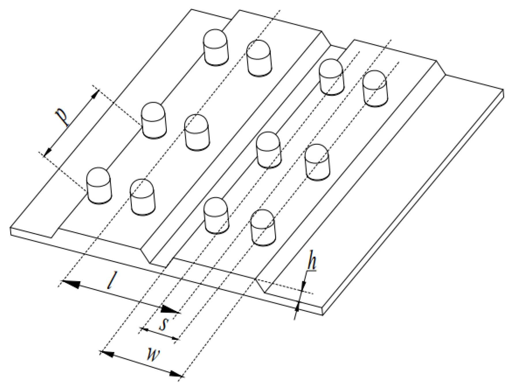
2.1.2. Cabbage and Chinese Cabbage Main Cultivation Patterns

To design a universal cabbage–Chinese cabbage harvesting platform, it is essential to understand the planting patterns of both cabbage and Chinese cabbage. The main cultivation practices for Chinese cabbage include single-row ridge planting, double-row ridge planting, and high-bed multi-row planting. High-bed multi-row planting is primarily used in sandy soils and is rarely seen in the Jiangsu–Zhejiang region. With the continuous development of seedling transplanting machines, the use of seedling transplanting methods has gradually increased, accounting for more than 90% of the double-row ridge planting for Chinese cabbage. Additionally, surveys indicate that double-row ridge planting is more common in nearby Chinese cabbage production bases. Therefore, the commonly practiced double-row ridge planting method in southern regions has been selected as the basis for the design. The specific agronomic parameters are shown in Figure 1: row spacing is 450~550 mm; plant spacing is 300~400 mm; ridge width is 800 mm; ridge distance is 900~1100 mm; and ridge height is 150~300 mm [13]. In the Jiangsu–Zhejiang region, the main cabbage planting mode is either a single-ridge double-row or four-row configuration. The standard is the single-ridge double-row planting pattern, with a ridge width of around 700 mm, a ridge height of 150~200 mm, a ridge distance of 950~1000 mm, row spacing of 450~500 mm, and plant spacing of approximately 350 mm [14].

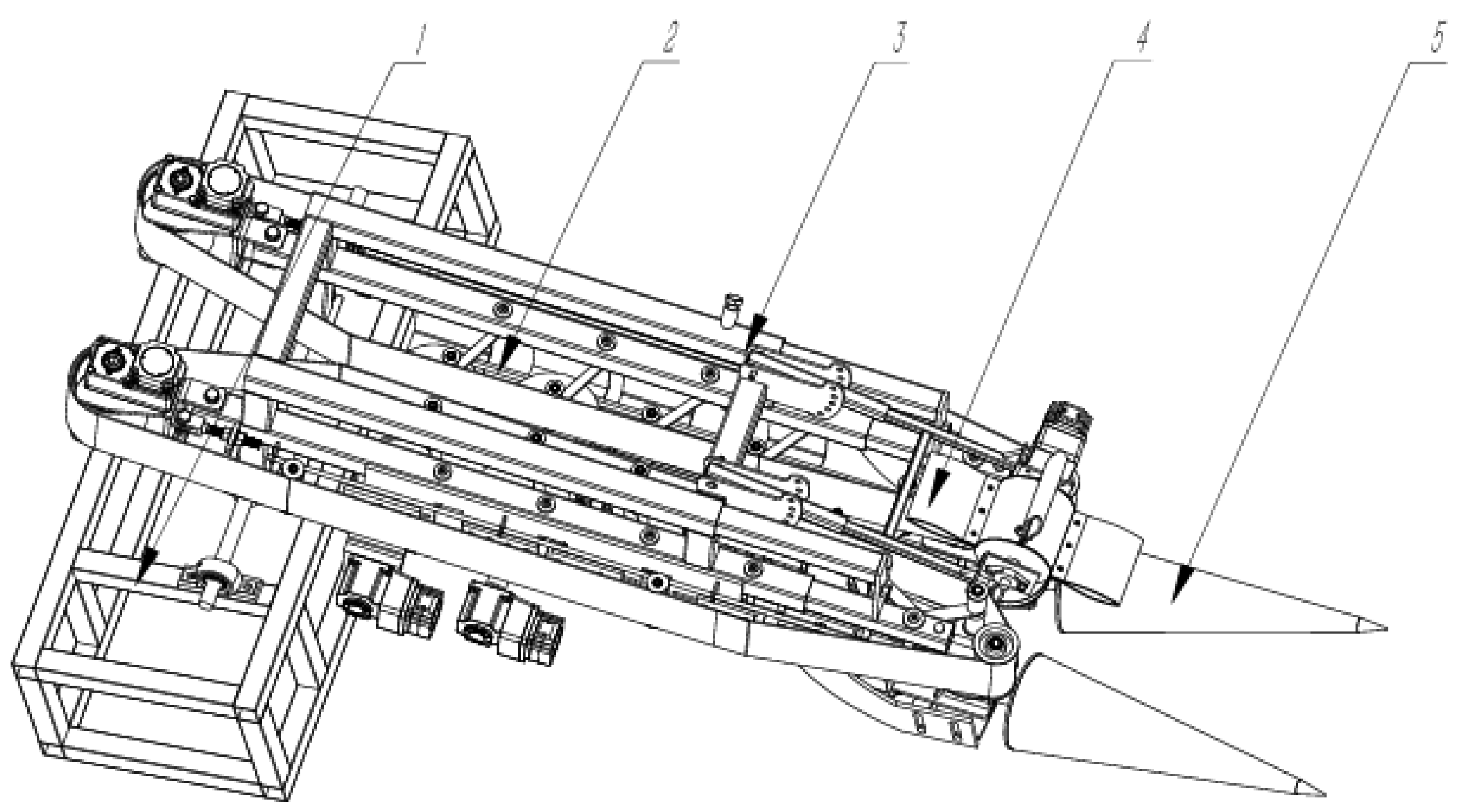
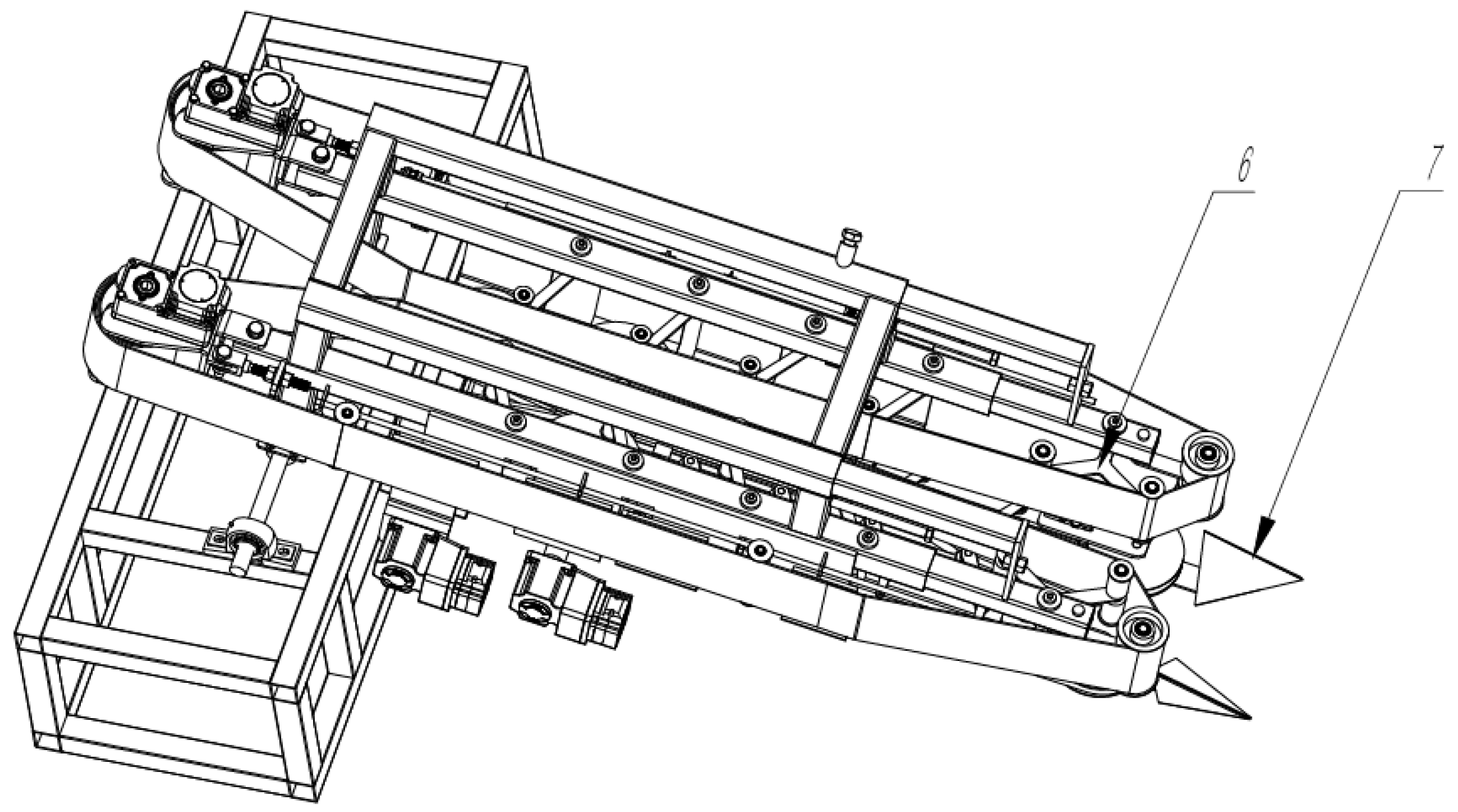
2.2. Overall Structure and Working Principle

2.2.1. Cabbage Harvesting

Based on the advantages and disadvantages of different harvesting methods for cabbage and Chinese cabbage, a single-row harvesting scheme was determined, where the cabbage is first pulled out and then conveyed for root-cutting.
The overall structure for harvesting cabbage is shown in Figure 2. It mainly consists of the control unit, clamping and conveying device, harvesting-unit frame, leaf-stripping wheel, and extraction roller. The control unit mainly houses control components such as the drive and converter. The clamping and conveying device includes a conveyor belt and a root-clamping belt, which can synchronize the gripping of both the cabbage head and root. The leaf-stripping wheel assists with feeding the cabbage into the system and can be raised to a higher position via different mounting holes when not in use. The extraction roller has a modular design and can be completely removed during Chinese cabbage harvesting.
During operation, as the harvesting platform moves forward, the extraction roller extends below the cabbage head to lift the cabbage. As the extraction roller rotates and the machine advances, the cabbage is conveyed toward the rear. At the end of the extraction roller, the cabbage is further pushed backward by the leaf-stripping wheel. With the assistance of the leaf-stripping wheel, the root part of the cabbage is clamped by the root-clamping belt and conveyed to the rear. Finally, at the end of the conveyor belt, the cabbage falls into the collection box, completing the entire harvesting process.

2.2.2. Chinese Cabbage Harvesting

The overall structure for harvesting Chinese cabbage is shown in Figure 3. At this time, the modular extraction roller needs to be removed, and the installation position of the leaf-stripping wheel needs to be adjusted upward to avoid interference with the Chinese cabbage during the harvesting process. Additionally, a feeding guide device must be installed, and the installation position of the root-clamping belt should be adjusted in the forward and backward directions. With these adjustments completed, the machine is ready for operation. It should be noted that the Y-type root extraction device is specifically designed for harvesting Chinese cabbage. During tests, it was found that not removing the extraction roller does not affect the cabbage harvesting, therefore, it remains in place during cabbage harvesting.
During operation, as the machine moves forward, the feeding guide device gathers the Chinese cabbage toward the center. The conveyor belt, in coordination with the Y-type root extraction device, pulls the Chinese cabbage out and conveys it to the rear. The root-clamping device immediately grips the root of the Chinese cabbage once it is pulled out. During transport, the speed of the root-clamping belt and conveyor belt can be manually matched to control the posture of the Chinese cabbage, ensuring that its axis is vertical to the upper surface of the frame. The Y-type root extraction device is available in five different sizes and can be swapped out to accommodate the size of different Chinese cabbage varieties, thus providing better extraction performance. Finally, at the end of the conveyor belt, the Chinese cabbage falls into the collection box, completing the entire harvesting process.

2.3. Technical Parameters

The universal cabbage and Chinese cabbage harvesting platform was completed in August 2024, with prototype testing, on site debugging, no-load testing, manual feeding of cabbage and Chinese cabbage, and several rounds of validation trials. The specific parameters obtained from the no-load test are shown in Table 3. This harvesting platform uses a single-row harvesting scheme, with overall dimensions of 2920 mm × 1380 mm × 1140 mm. It is suitable for cabbage and Chinese cabbage heads with a diameter range of 50~280 mm. The maximum conveyor belt and root-clamping belt speeds are 300 RPM, the maximum speed of the leaf-stripping wheel is 100 RPM, and the maximum speed of the extraction roller is 500 RPM. The angle between the platform and the ground can be adjusted within the range of 5° to 30°.

3. Structure Design and Motion Analysis of Key Components

3.1. Cabbage Extraction Device

3.1.1. Structural Design of the Leaf-Stripping Wheel

The overall structure of the leaf-stripping wheel is shown in Figure 4. The blades of the leaf-stripping wheel are made of high-elasticity bull tendon board material and are fixed onto the wheel with bolts. Driven by a motor, these components are assembled together on a mounting frame. The mounting frame is designed to be retractable, allowing for the adjustment of its stroke so that the leaf-stripping wheel and extraction rollers can work in better coordination. The mounting frame is secured to the mounting plate via a pin, and the mounting plate is pre-drilled with holes of varying heights. During operation, different holes can be selected to adjust the ground clearance of the stripping wheel, thereby adapting to different working environments. The mounting plate is welded to the harvesting section frame of the test platform.

3.1.2. Force Analysis of the Leaf-Stripping Wheel

When the leaf-stripping wheel is in operation, its motion is a combination of the forward movement of the universal harvesting platform and the rotational motion of the stripping wheel around its axis. The motion trajectory can be determined using graphical methods, and the specific trajectory is shown in Figure 5. It is important to note that the radius R r of the stripping wheel is the sum of the wheel and the blades [12].
If the stripping wheel is equipped with n m blades, the forward distance of the harvester corresponding to each blade rotation can be calculated using the following formula:
S = v m 60 n m n r
where v m is the forward speed of the harvesting platform, (m·s−1); n m is the number of blades, (blade); n r is the rotational speed of the stripping wheel, (RPM).
Taking the projection point O 1 of the center point O of the stripping wheel on the ground as the coordinate origin, the forward direction of the cabbage harvester as the positive X-axis, and the vertical upward direction as the positive Y-axis, the trajectory equation of the outermost horizontal point A 0 of the blade rotating clockwise is as follows:
x = v m t + R r cos ω r t y = H r R r sin ω r t
where R r is the radius of the stripping wheel, (m); ω r is the angular velocity of the stripping wheel, (rad·s−1); H r is the vertical height of the center point of the stripping wheel from the ground, (m).
The movement pattern of the stripping wheel varies and mainly depends on the ratio λ 1 of the circumferential velocity v y of the stripping wheel to the forward speed v m of the universal harvesting platform, known as the stripping wheel speed ratio, calculated as follows:
λ 1 = v y v m
The value of λ 1 can vary from 0 to ∞. When λ 1 is equal to ∞, the stripping wheel’s trajectory is circular. When λ 1 ∈ [1,∞), the trajectory is a prolate cycloid. When λ 1 = 1, the trajectory is a standard cycloid. When λ 1 ∈ (0,1), the trajectory is a curtate cycloid. When λ 1 = 0, the trajectory is a straight line. From the cabbage harvesting process, it can be observed that the stripping wheel must have a rearward velocity component to effectively guide the cabbage backward. Therefore, the designed value of λ 1 should be greater than 1. However, as λ 1 increases, the frequency of blade contact with the cabbage also increases, potentially leading to damage to the top of the cabbage. Thus, the choice of λ 1 should also consider the risk of cabbage damage [15,16].
During the assisted feeding process of the stripping wheel, the spacing between the stripping blades and the mounting plate must accommodate a single cabbage. This means that the arc length between the mounting plates should be greater than the cabbage diameter. Therefore, the design of the stripping wheel should satisfy the following condition:
2 π R r n m > D b
where D b is the head diameter of the cabbage, (mm).
Based on the statistical analysis of cabbage physical parameters in Table 1, calculations were performed to set the number of blades n m to four and determine the stripping wheel radius R r as 300 mm. Substituting into the left side of Equation (4) gives 471.23 mm. According to Table 1, all cabbages have a diameter of less than 280 mm, satisfying Equation (4), confirming the rationality of the stripping wheel design.
The effect of the stripping wheel on the cabbage is shown in Figure 6. The stripping wheel mainly functions to guide and push the cabbage backward. To ensure the continuous harvesting of cabbage, the stripping blades can act on the cabbages either continuously or intermittently. The pitch S r between the epicycloid hooks of the stripping wheel should satisfy the following relationship [17]:
S r = 2 π R r n m λ 1 = S p z
where S r is the pitch between the epicycloid hooks of the stripping wheel, (mm); S p is the plant spacing of cabbage, (mm); z is the blade action interval, generally set to 1, 2, or 3.
Based on the previous design and statistical analysis, the radius of the stripping wheel R r is set to 300 mm, the number of blades n m is four, and the cabbage planting spacing S p ranges from 350 mm to 400 mm. With an action interval z of 1, substituting four values into Equation (5) yields a speed ratio λ 1 of 1.18 to 1.34, which falls within the recommended range. The resulting epicycloid trajectory is a long-pitch curve, ensuring continuous operation and validating the design.
Once the value of λ 1 is determined, the rotational speed of the stripping wheel n r is also established as follows:
n r = 30 λ 1 v m π R r
Given that the forward speed of the universal harvesting test bench v m is 0~0.34 m·s−1, substituting this into Equation (6) results in a stripping wheel speed n r range of 0 to 14.5 RPM. Therefore, a 300 W DC motor with a rated output speed of 100 RPM is selected to drive the stripping wheel. The motor operates at 48 V, includes an onboard encoder, and its speed can be adjusted via the human–machine interface.

3.1.3. Design of the Extraction Roller Structure

The structure of the extraction roller is shown in Figure 7. The extraction roller mainly consists of a pair of conical rollers, a coupling, an extraction roller mounting plate, a frame mounting plate, and a motor mounting plate. The motor is connected to the extraction roller through the coupling, and all three components are fixed on the motor mounting plate. The motor mounting plate is connected to the extraction roller mounting plate by bolts. Both plates have elongated slots, allowing for the adjustment of the relative distance between the two extraction rollers. The extraction roller mounting plate is also connected to the frame mounting plate by bolts, and the vertical position of the extraction rollers can be adjusted through the elongated slots. The entire extraction roller assembly is fixed onto the frame by the frame mounting plate. Based on previous experimental experience, the opening of the extraction roller is fixed at 25°.

3.1.4. Force Analysis of the Extraction Roller

During the operation of the extraction roller, it needs to lift the cabbage upward and transport it backward. Therefore, the force analysis of the extraction roller when extracting the cabbage is particularly important. For the sake of simplifying the analysis, the cabbage and extraction roller are considered as a rigid system. Additionally, this rigid system is further simplified by considering the centroid of the cabbage during the extraction process as being along the upper surface of the extraction roller. As shown in Figure 8, the axis of the conical roller is set as the X-axis, and the vertical upward direction is the Y-axis. A kinematic analysis diagram of the extraction roller extracting a cabbage is established.
According to the centroid motion theorem of the system, the dynamic equations in the X and Y directions can be established [18,19]:
m 1 a x = F x e m j a e + m 1 a e m 1 a r cos δ = F j sin δ
m 1 a y = F y e m 1 a r sin δ = F m m j + m 1 g F j cos δ
where a e represents the absolute acceleration of the harvesting test bench, (m·s−2); a r represents the relative acceleration of the cabbage, (m·s−2); m j represents the weight of the extraction roller, (kg); F j represents the extraction force exerted by the extraction roller on the cabbage, (N); F m represents the force exerted by the ground on the entire rigid system, (N); δ represents the horizontal angle of the extraction roller, (°); m 1 represents the mass of the cabbage plant, (kg).
As shown in Figure 9, a separate kinematic analysis of the cabbage is conducted. The upper surface of the conical roller is taken as the X-axis, and the vertical direction is the Z-axis, establishing the coordinate system as shown in the figure.
According to the centroid motion theorem, the following can be obtained:
m 1 a x = F x e m 1 a e cos δ m 1 a r = m 1 g sin δ μ 1 F j
m 1 a y = F y e F j m 1 g cos δ = m 1 a e sin δ
where μ 1 is the coefficient of friction between the cabbage and the extraction roller.
From Equation (10), the extraction force F j can be derived as follows:
F j = m 1 a e sin δ + m 1 g cos δ
Substituting Equation (11) into Equation (9), the relationship between a r and a e can be derived:
a r + g sin δ μ 1 g cos δ = a e μ 1 sin δ + cos δ
Substituting Equation (11) into Equation (7) also leads to the relationship between a r and a e :
m 1 a r cos δ + m 1 g sin δ cos δ = a e m j + m 1 cos 2 δ
By solving Equations (12) and (13) simultaneously, the values of a r and a e can be determined:
a e = μ 1 m 1 g cos 2 δ m j μ 1 m 1 sin δ cos δ
a r = g ( μ 1 m j cos δ + μ 1 m 1 cos δ m j sin δ ) m j μ 1 m 1 sin δ cos δ
In order to ensure that the cabbage moves upward along the surface of the conical roller during the extraction process, the value of a r must be greater than 0, and the value of δ must be less than 45°. Therefore, the condition for the upward movement of the extraction roller is as follows:
tan δ μ 1 < 1 + m 1 m j
From Equation (16), it can be seen that the upward movement of the cabbage along the extraction roller is significantly affected by the coefficient of friction μ 1 and the horizontal angle δ of the extraction roller. The larger the coefficient of friction between the extraction roller and the cabbage, and the smaller the horizontal angle δ , the more favorable it is for the cabbage to be pulled.
When selecting the material for the extraction roller, it is also necessary to consider that the surface of the extraction roller, when rotating and in contact with the ground, should not accumulate a large amount of soil during the forward movement. The surface should also have a certain degree of smoothness and possess corrosion resistance and wear resistance. Therefore, 304 stainless steel is chosen as the material for the conical roller. Based on experience, the coefficient of friction μ 1 is taken as 0.3 [20,21]. In the selection of the horizontal angle δ of the extraction roller, considering the coordination of the mechanism and other experiences, it is chosen to be 15° [22]. Based on the weight statistics of the cabbage in Table 1, m 1 is taken as 4.02 kg. The weight of the conical roller was estimated using SolidWorks 2023, with m j set to 4.2 kg. Substituting all of these four parameters into Equation (16), we obtain the following:
0.893 < 1.957
This satisfies the design requirements. In addition, based on experience, the speed of the extraction roller is 0~500 RPM. A 500 W DC motor is used for the extraction roller, with a rated output speed of 500 RPM. The motor operates at 48 V, includes an onboard encoder, and its speed can be adjusted via the human–machine interface.

3.2. Chinese Cabbage Extraction Device

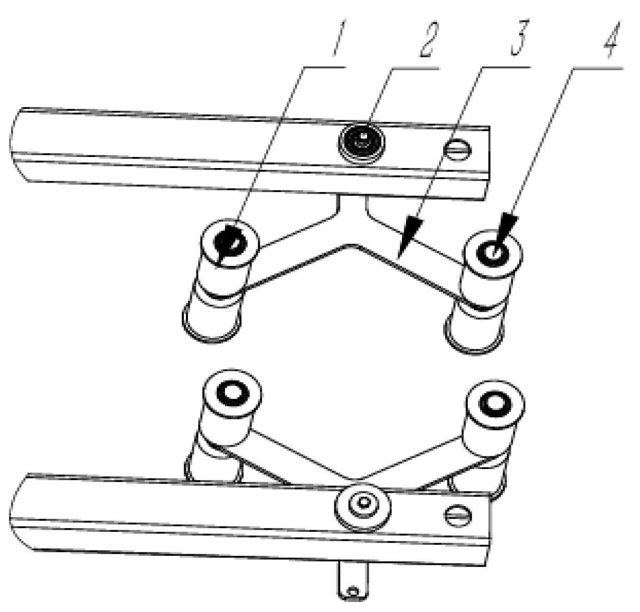
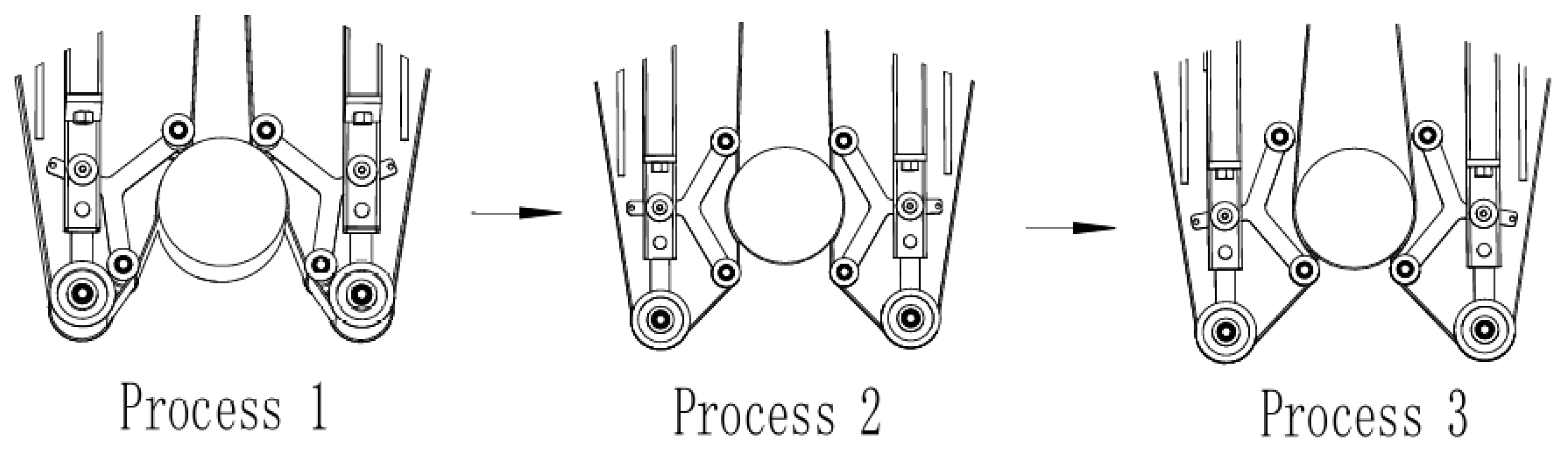
3.2.1. Design of the Y-Type Extraction Device Structure

The Y-type extraction device has a symmetrical structure on both sides. Figure 10 shows a schematic diagram of a pair of Y-type extraction devices installed on the harvesting-unit frame. The Y-type extraction device mainly consists of a clamping roller, a rotating shaft, a Y-type mounting plate, and a clamping shaft. The rotating shaft and clamping shaft are welded onto the Y-type mounting plate, and the clamping roller is fixed on the clamping shaft by a snap ring. The outer end of the Y-type mounting plate has a through hole to attach one end of the spring. The spring’s elasticity ensures the reset after each extraction action. During installation, the rotating shaft is inserted into the through hole on the harvesting-unit frame, allowing the entire Y-type extraction device to rotate around the center of the through hole.
The specific working process of the Y-type extraction device is shown in Figure 11. In Process 1, the conveyor belt begins to make contact with the Chinese cabbage. As the machine moves forward and the conveyor belt rotates, the cabbage is slowly pulled upward. In Process 2, the two Y-type extraction devices are positioned opposite each other. At this point, the extraction force exerted by the Y-type extraction device on the cabbage reaches its maximum value, and the cabbage is pulled out by the roots. In Process 3, the cabbage is held by the conveyor belt and transported backward. The Y-type extraction device resets through the elasticity of the spring. At this point, the entire extraction process for a single Chinese cabbage is completed. From Process 2, it can be seen that the conveyor belt undergoes deformation, and the contact surface with the cabbage becomes curved. This greatly increases the contact area with the Chinese cabbage and reduces the force applied per unit area. This demonstrates that the combination of the Y-type extraction device and the conveyor belt for Chinese cabbage extraction can significantly reduce the damage during the Chinese cabbage extraction process.

3.2.2. Mechanical Analysis of the Y-Type Extraction Device

As shown in Figure 12, a force analysis is conducted during the Chinese cabbage extraction process. A coordinate system is established with the forward direction as the X-axis and the direction perpendicular to the forward direction as the Y-axis.
The forces involved in the Chinese cabbage extraction process are governed by the following Equations:
F 2 = F 3 + F 4 + G cos ε
F 2 = μ 2 F 1
where F 1 is the clamping force on the Chinese cabbage, (N); F 2 is the extraction force exerted by the extraction device on the Chinese cabbage, (N); F 3 is the extraction inertial force of the cabbage, (N); F 4 is the soil resistance during cabbage extraction, (N); μ 2 is the coefficient of friction between the Chinese cabbage and the conveyor belt; ε is the harvesting angle of the universal harvesting platform, (°); G is the weight of the Chinese cabbage plant, (N).
Since the Chinese cabbage extraction process is slow and difficult to calculate, the inertial force F 3 during the extraction process is neglected. Apart from its own weight, the Chinese cabbage primarily experiences vertical forces from the soil’s shear force, soil resistance, and the gravitational force of soil adhered to the Chinese cabbage roots. Based on experimental observations, after the Chinese cabbage is pulled out, the surrounding soil does not form an arching phenomenon. Therefore, the vertical shear force from the soil is not considered. The gravitational force of soil adhered to the Chinese cabbage roots can be obtained by subtracting the weight of the Chinese cabbage from the force measurement taken after extracting it, which was experimentally measured as 9.6 N. Therefore, the total soil resistance is the friction between the soil and the Chinese cabbage roots, as well as the gravitational force of the soil adhered to the roots [23].
In summary, at a distance h from the top of the conveyor belt, a thin disk with radius r is considered. The soil resistance to the Chinese cabbage extraction F 4 is given by the equation below:
F 4 = 0 A 2 π r μ 3 γ K h d h + 9.6
where r is the radius of the Chinese cabbage sphere, (mm); μ 3 is the maximum static friction coefficient between the soil and the root stalk; γ is the soil bulk density, (N·m−3); K is the lateral soil pressure coefficient; A is the width of the conveyor belt, (mm); h is the distance from the top of the conveyor belt to the thin disk with radius r , (mm).
From Equations (18)–(20), we obtain the following:
F 2 = 0 A 2 π r μ 3 γ K h d h + G cos ε + 9.6
F 1 = 0 A 2 π r μ 3 γ K h d h + G cos ε + 9.6 μ 2
The conveyor belt width A is 250 mm. According to Table 2, the selected Chinese cabbage diameter is 185 mm. The static friction coefficient between spinach roots and soil is 0.8 [24]. Since both the extraction force and root length of Chinese cabbage are more than twice those of spinach, μ 3 is set to 1.2. The measured soil bulk density γ is 14,200 N·m3. Substituting the above parameters into Equation (20), the value of F 4 is calculated to be 223.5 N.
According to Table 2, the selected Chinese cabbage weight is 3.19 kg. The lateral soil pressure coefficient K is calculated using the formula K = 1 sin ε . The measured harvesting angle ε of the universal harvesting platform is 18°. Substituting these two parameters into Equation (21), the value of F 2 is calculated to be 259.4 N.
The friction coefficient μ 2 between the Chinese cabbage and the conveyor belt is selected as 0.81 [25]. Substituting this into Equation (22), the value of F 1 is calculated to be 320.2 N.
The clamping force F 1 on the Chinese cabbage is much smaller than the Chinese cabbage’s breaking force of 1364.7 ± 171.95 N, meaning that the extraction device will not crush the Chinese cabbage’s sphere. The extraction force F 2 is greater than the Chinese cabbage extraction force measured in the field (171.95 ± 20.04 N), meaning that the Chinese cabbage can be pulled up successfully. In conclusion, the design of the Y-type extraction device is reasonable.

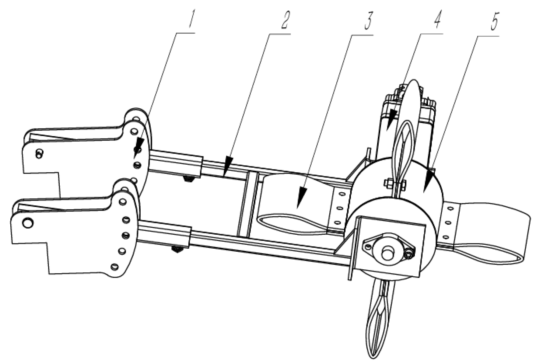
3.3. Clamping and Conveying Device Design and Analysis

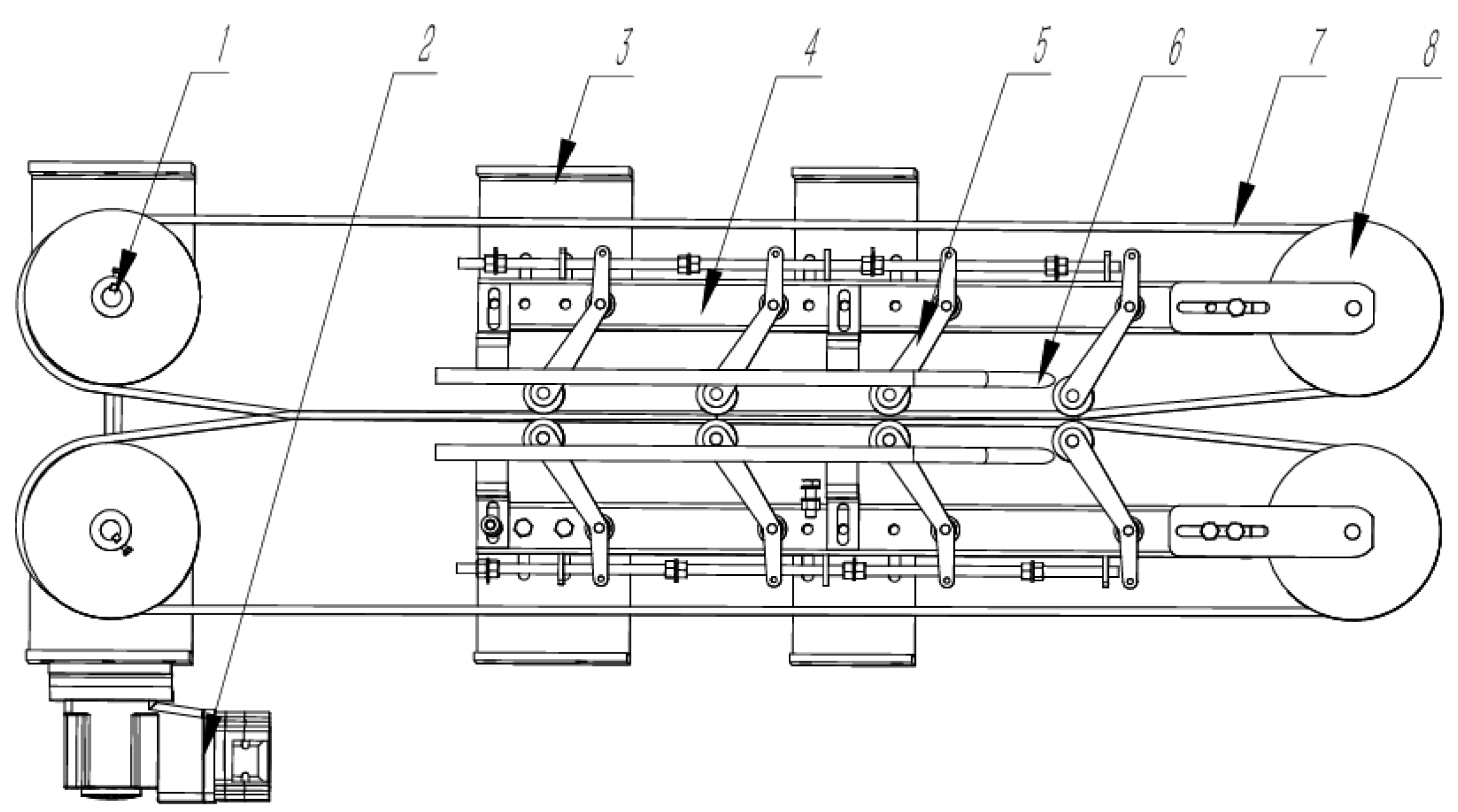
3.3.1. Structural Design of the Clamping Device

As shown in Figure 13, the clamping device mainly consists of the driving wheels, driven wheels, tensioning device, driving motor, harvesting-unit frame, and conveyor belt. All components are mounted on the harvesting-unit frame. During operation, the driving motor rotates the driving wheel, which, through friction, drives the conveyor belt. The entire clamping device operates successfully. The tensioning device is connected to a tensioning spring at its end, with the other end of the spring connected to the mounting plate on the outer screw. The mounting plate is fixed on the screw using a pair of nuts. By adjusting the position of the nuts, the clamping distance of the tensioning device can be changed. Based on the ball diameter of cabbage and Chinese cabbage from Table 1 and Table 2, the clamping distance of the device is set to be between 80 mm and 280 mm.

3.3.2. Structural Design of the Root-Clamping Device

As shown in Figure 14, the root-clamping device mainly consists of the driving wheels, driven wheels, driving motor, root-clamping device mounting plate, root-clamping-device frame, tensioning device, limiting device, and root-clamping belt. During operation, the driving motor rotates the driving wheel, and the root-clamping belt—which is a double-sided toothed synchronous belt—achieves synchronous rotation through the engagement of teeth with the driving wheel. During harvesting, cabbage and Chinese cabbage are clamped by both the root-clamping device and the clamping device after being pulled. The root-clamping belt is installed at a certain angle relative to the plane of the limiting device. As the cabbage and Chinese cabbage are conveyed backward, the downward force from the root-clamping belt ensures the cabbage tightly fits against the limiting device. This limiting device can solve the issue of variation in the optimal cutting position caused during the extraction and conveying processes. The clamping distance of the root-clamping device is set to be between 0 mm and 60 mm.

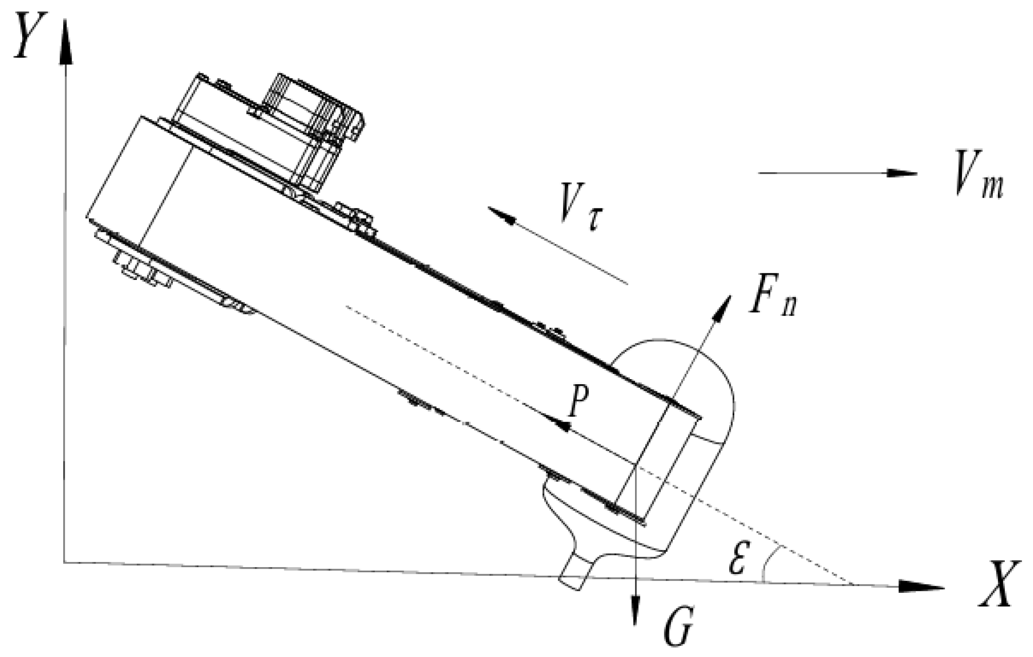
3.3.3. Mechanical Analysis of the Clamping and Conveying Device

As mentioned earlier, the clamping and conveying device adopts a dual clamping method using both the clamping device and the root-clamping device. The primary function of the root-clamping device is to secure the roots of cabbage and Chinese cabbage without concerns about damage. Therefore, the kinematic analysis is focused only on the clamping device. In the cabbage harvesting process, when the cabbage reaches the end of the extraction roller, it is clamped by the root-clamping device with the assistance of the reel. After being constrained by the limiting device, it is further clamped by the clamping device. Throughout this process, the cabbage remains undamaged and maintains a stable posture. Compared to cabbage, the harvesting process for Chinese cabbage involves direct extraction using the Y-type extraction device. After being pulled out, the Chinese cabbage is initially clamped only by the clamping device before being conveyed further and clamped again. During this phase, when held solely by the clamping device, the posture of the Chinese cabbage may change. Therefore, this section focuses on the kinematic analysis of the Chinese cabbage when it is solely clamped by the clamping device.
As shown in Figure 15, a force analysis is conducted on the Chinese cabbage plant during clamping and conveying. A coordinate system is established with the forward direction as the X-axis and the vertical upward direction as the Y-axis.
During conveying, the Chinese cabbage is subjected to its own weight, the conveying force of the clamping device, and the support force. Under the action of these forces, the entire system is in equilibrium. The force analysis can be expressed as follows [26,27]:
P = G sin ε
F n = G cos ε
where P is the conveying force of the ball-clamping device, N; F n is the support force provided by the ball-clamping device on the Chinese cabbage, N; ε is the harvesting angle of the platform, °; G is the weight of the Chinese cabbage, N.
From Equations (23) and (24), it can be seen that the conveying force P and the support force F n on the Chinese cabbage depend on the weight G of the Chinese cabbage and the inclination angle ε of the conveyor belt. As ε increases, the conveying force P increases while the support force F n decreases. The conveying force P is mainly generated by the friction between the two conveyor belts. When P increases, it may affect the posture of the Chinese cabbage. Conversely, when ε decreases, P decreases and F n increases. However, a smaller inclination angle will increase the conveying time on the inclined surface, which in turn affects the conveying efficiency of the clamping device. In summary, the inclination angle ε of the conveyor belt is a key parameter affecting both the operational performance and efficiency of the universal harvesting platform [28].
The performance of the clamping and conveying operation is closely related to the conveying speed. A speed that is too high may affect the stability of conveying and cause changes in the posture of the Chinese cabbage, while a speed that is too low may lead to clogging and other issues. As shown in Figure 16, a kinematic analysis of the Chinese cabbage is carried out.
During the clamping and conveying process, the motion velocity of Chinese cabbage is the vector sum of the forward speed of the universal harvesting platform and the speed of the clamping and conveying belt. The velocity vector relationship is expressed as follows [29]:
V n = V τ + V m
where V n is the absolute speed of the Chinese cabbage, (m·s−1); V τ is the speed of the clamping and conveying belt, (m·s−1); V m is the forward speed of the harvesting platform, (m·s−1).
In order to prevent blockage at the feeding inlet during the harvesting operation, the forward speed V m of the platform and the clamping and conveying belt speed V τ should satisfy the following [30]:
V τ cos ε > V m
Based on the trigonometric relationships shown in Figure 16, we obtain the equations below:
V τ cos 90 ° + φ ε = V m sin 90 ° φ
V n sin ε = V m sin 90 ° φ
From Equations (27) and (28), the following ratio can be derived:
V τ V m = sin 90 ° + φ ε sin 90 ° φ = λ 2
where φ is the angle between the central axis of the Chinese cabbage and its absolute velocity, (°); λ 2 is the ratio of the clamping and conveying belt speed V τ to the forward speed V m of the harvesting platform.
From Equations (25) and (29), it can be seen that during the clamping and conveying process of Chinese cabbage, in order to ensure efficient and stable conveying, the speed of the clamping and conveying belt V τ and the forward speed of the harvesting platform V m must satisfy a certain proportional relationship. This proportional relationship is ultimately reflected in the speed ratio coefficient λ 2 .

4. Soil-Trough Harvesting Experiment

4.1. Soil-Trough Experimental Conditions

The overall structure of the test platform is shown in Figure 17. The test platform consists of a control unit, a drive unit, and a walking chassis. The drive unit contains a driver, voltage converter, and switching power supply, all of which are installed on the walking chassis. The walking chassis mainly comprises the chassis frame, power converter, drive axle, and stepper motor. All these components are mounted on the chassis frame. During operation, the power converter converts 380 V AC power into 48 V DC power. The stepper motor provides the driving force, which powers the drive axle, ultimately driving the entire test platform forward. The CPU selected is the Siemens S7-1200 series PLC, model 6ES7214-1AG40-0XB0, which is suitable for data processing and logic control in automated control and monitoring systems. The manufacturer is Siemens, headquartered in Germany.
The control unit of the test platform is used in this experiment. This can not only adjust and monitor the speeds of the extraction roller, leaf-stripping wheel, root-clamping belt, conveyor belt, and walking chassis but can also control the raising, lowering, starting, and stopping of the cutting table. In addition, it can control the forward, reverse, and stop motions of the walking chassis. The human–machine interface panel of the test platform control system is shown in Figure 18.
The clamping force measurement device consists of a root-clamping device and a force measurement device. The root-clamping device mainly includes a mounting base, aluminum profile, and clamp, as shown in Figure 19. The mounting base is connected to the aluminum profile with bolts, and by adjusting the tensioning device, both ends of the mounting base can be securely attached to the sidewalls of the soil trough. The clamp is a 360° rotating bench vise with a clamping range of 0~70 mm. During use, the clamp is placed below the aluminum profile, and the bolts are tightened to firmly secure the entire clamp to the aluminum profile. One side of the clamp has a handle that allows for manual adjustment of the clamping force.
As shown in Figure 20, the force measurement device consists of an extraction force measurement platform and a force measurement system. The extraction force measurement platform, shown in (a), mainly comprises an aluminum profile frame and a horizontal tensile testing machine. The horizontal tensile testing machine is fixed onto the aluminum profile frame using bolts. It primarily consists of a horizontal rack and a dial-type push–pull gauge. The dial-type push–pull gauge is manufactured in Shenzhen, China. The testing platform is purchased as a pre-assembled unit, and during use, the hand-crank mechanism of the testing machine is manually rotated to position the force gauge correctly. The force measurement system, shown in (b), consists of a thin-film pressure display, which is factory-calibrated. The thin-film pressure display is manufactured in Beijing, China. During testing, the sensor is placed between the clamp and the root of the cabbage or Chinese cabbage to measure the real-time clamping force, which is then converted into the extraction force.
The force analysis is shown in Figure 21. In the horizontal direction, the root of the cabbage and Chinese cabbage is subjected to a pair of opposing clamping forces F a . In the vertical direction, it is subjected to an upward extraction force F b , while the downward forces include its own weight m g and twice the friction force μ 4 F a .
From the force equilibrium Equation, the following is obtained:
F b = m g + 2 μ 4 F a
When adjusting the hand-crank device on the root-clamping mechanism, the clamping force is manually controlled and cannot be infinitely large. During each test, the adjustment was made until it could no longer be turned by hand. A total of 10 tests were conducted, and the average value was taken.

4.2. Experimental Conditions, Methods, and Results for Chinese Cabbage

4.2.1. Experimental Conditions for Chinese Cabbage

As shown in Figure 22, the developed universal harvesting platform was tested in a soil-trough harvesting experiment for Chinese cabbage in January 2025. A batch of Chinese cabbage “Huangxin” was purchased from a local farmer around the school. At the time of purchase, the seller was instructed to first loosen the soil using a tool, then pull the entire Chinese cabbage plants out of the ground without any further processing and load them directly onto a truck to transport to the school. The measurements were taken approximately 2 h after the Chinese cabbage was pulled from the ground. Prior to measurement, the soil on the roots was removed, and then the total mass, spherical diameter, plant height, root diameter, root height, and root length of the Chinese cabbage were measured. The number of samples selected for the measurement was 50 heads.
The specific physical property parameters of the Chinese cabbage are shown in Table 4.
During the experiments, the average clamping force F a was measured to be 232.1 N, and the average extraction force F b was 125.1 N. When these values, along with the measured weight of the Chinese cabbage, were substituted into Equation (30), the value of μ 4 was obtained as 0.218. In the experiment, the clamping force F a was fixed and adjusted to 230 N. Based on the weight data in Table 4, the range of extraction forces in the soil-trough harvesting test was calculated to be 115.67~129.48 N, with an average value of 124.09 N.

4.2.2. Experimental Methods for Chinese Cabbage

Currently, there is a lack of dedicated experimental methods and related operational quality evaluation standards specifically for Chinese cabbage harvesters in China. Therefore, based on the relevant methods and operational standards for cabbage and sugar beet harvesting (JB/T 6276-2007, GB/Z 26582-2011), this paper proposes the following evaluation indicators: extraction success rate, clamping and conveying success rate, and operational damage rate [31,32].
(1)
Extraction Success Rate
The extraction success rate is defined as the percentage of Chinese cabbage plants that are successfully pulled by the extraction device relative to the total number of harvested Chinese cabbages. During the experiment, the number of successfully pulled Chinese cabbages and the total number harvested were recorded.
Q p = N p N × 100
where Q p is the extraction success rate, %; N p is the number of Chinese cabbages successfully pulled, heads; N is the total number of harvested Chinese cabbages, heads.
(2)
Clamping and Conveying Success Rate
The clamping and conveying success rate is defined as the percentage of successfully pulled Chinese cabbages whose roots are properly clamped by the root-clamping device and whose cabbage spheres maintain an orientation such that the axis of the sphere is perpendicular to the inclined plane of the frame during the clamping and conveying process. During the experiment, the number of Chinese cabbages that were successfully clamped and conveyed was recorded.
Q s = N s N p × 100
where Q s is the clamping and conveying success rate, %; N s is the number of Chinese cabbages successfully clamped and conveyed, heads.
(3)
Operational Damage Rate
The operational damage rate is defined as the percentage of Chinese cabbages that are damaged during the entire harvesting process due to the actions of the harvesting platform. During the experiment, the number of Chinese cabbages that were damaged was recorded.
Q c = N c N × 100
where Q c is the operational damage rate, %; N c is the number of Chinese cabbages damaged during operation, heads.
To verify the performance of the harvesting platform in the extraction and clamping–conveying stages for Chinese cabbage, the following single-factor experiments were designed. First, the conveyor belt speed and the forward speed were selected as the experimental factors. It should be noted that the linear speed of the conveyor belt should be the same as that of the root-clamping belt. During debugging, it was found that the two speeds have a 1.2:1 ratio. However, for the experiment, only the conveyor belt speed was chosen as the experimental factor. The initial level for the conveyor belt speed was set to 60 RPM, which corresponds to a root-clamping belt speed of 50 RPM. The initial level for the forward speed was set to 1 km·h−1. Using the method of controlling variables, one experimental factor was changed at a time while keeping the other factors constant. Each experimental factor was selected at five different levels, and each set of the experiment was repeated three times. In each trial, 10 Chinese cabbages were harvested.
(1)
Single-factor experiment for forward speed: During the experiment, the conveyor belt speed was fixed at 60 RPM. The forward speed started at 0.8 km·h−1, and in each experiment, the forward speed was increased by 0.1 km·h−1. A total of five groups of experiments were conducted, with the maximum forward speed reaching 1.2 km·h−1;
(2)
Single-factor experiment for conveyor belt speed: During the experiment, the forward speed was fixed at 1 km·h−1. The conveyor belt speed started at 40 RPM, and in each experiment, the speed was increased by 10 RPM. A total of five groups of experiments were conducted, with the maximum conveyor belt speed reaching 80 RPM.

4.2.3. Experimental Results and Analysis for Chinese Cabbage

As shown in Figure 23, with the conveyor belt speed kept constant, the extraction success rate first levels off and then decreases rapidly. The reason for this rapid decline is that when the forward speed of the harvesting platform exceeds the linear speed of the clamping conveyor, the forward-moving platform will cause the Chinese cabbage to fall over. Chinese cabbages that fall over cannot be successfully pulled. The clamping conveyor success rate fluctuates between 95.5% and 100%, which indicates that the success rate of clamping and conveying is largely unaffected by the forward speed. It also shows that the posture of the Chinese cabbage is not easily altered during the clamping and conveying process. The operational damage rate first increases gradually and then increases sharply, which is strictly related to the extraction success rate. The damage to the Chinese cabbage during the harvesting process mainly results from posture changes during the extraction process, which causes the root-clamping belt to damage the Chinese cabbage.
From the single-factor experiment of the forward speed of Chinese cabbage, it can be concluded that matching the conveyor belt speed and the forward speed of the harvesting platform is crucial. The clamping and conveying success rate is not significantly correlated with the forward speed. The damage rate of the Chinese cabbage during the operation is strictly related to the extraction success rate.
As shown in Figure 24, with the forward speed kept constant, the extraction success rate initially increases rapidly and then levels off. The reason for the rapid increase is again that the forward speed of the platform and the conveyor belt’s linear speed are mismatched. The slow decrease is mainly due to the increased conveyor belt speed, which reduces the reliability and stability of the entire clamping and conveying system. The clamping and conveying success rate first levels off and then gradually decreases, with the main influencing factor being the reliability of the clamping and conveying system. The faster the speed, the lower the reliability. The operational damage rate is strictly related to the extraction and conveying success rate. Chinese cabbages that are damaged during the harvesting process are mainly those that had posture changes during the extraction and feeding process, leading to the root-clamping belt injuring the Chinese cabbage’s body.
From the single-factor experiment of the conveyor belt speed, it is concluded that matching the conveyor belt speed and the forward speed of the harvesting platform is crucial. The damage rate of the Chinese cabbage during the operation is strictly related to the extraction success rate, and an increased conveyor belt speed affects the reliability of the clamping and conveying system.

4.3. Experimental Conditions, Methods, and Results for Cabbage

4.3.1. Experimental Conditions for Cabbage

As shown in Figure 25, the universal harvesting platform was tested for cabbage harvesting in December 2025. A batch of cabbage was purchased from the Dongtai Chunli Fresh Vegetable Cooperative in Yancheng, Jiangsu Province. The cabbage variety was “Aoqina”. The purchasing requirements, measurement tools, and methods were consistent with the Chinese cabbage experiment. The time from when the cabbage was pulled from the soil to the measurement was approximately 8 h. The number of samples selected for the measurement was 50 heads.
The specific physical properties of the cabbage are listed in Table 5.
The average clamping force F a was 236.2 N, and the average extraction force F b was 114.6 N. Using the measured cabbage weight and plugging it into Equation (30), the value of μ 4 was calculated as 0.163. During the experiment, the clamping force F a was fixed at 230 N. Based on the cabbage weight from Table 5, the range of extraction forces in this experiment was between 99.97 N and 123.39 N, with an average extraction force of 112.71 N.

4.3.2. Experimental Methods for Cabbage

Currently, there is a lack of specific testing methods and operational quality evaluation standards for cabbage harvesters in China. Therefore, based on related methods and operational standards for cabbage and beet harvesting (JB/T 6276-2007, GB/Z 26582-2011), this study proposes the use of the following evaluation indicators: extraction and feeding success rate, conveying success rate, and operational loss rate [31,32].
(1)
Extraction and Feeding Success Rate
The extraction and feeding success rate refers to the proportion of cabbage plants that are successfully pulled by the extraction rollers and smoothly fed into the root-clamping device. During the experiment, the number of successfully pulled and fed cabbages and the total number of harvested cabbages were measured.
L p = M p M × 100
where L p is the extraction success rate, %; M p is the number of cabbages successfully pulled, heads; M is the total number of harvested cabbages, heads.
(2)
Conveying Success Rate
The conveying success rate refers to the proportion of cabbages that, after being successfully pulled and fed, are clamped and transported without falling off while maintaining a stable posture during transport. The number of successfully transported cabbages was measured during the experiment.
L s = M s M p × 100
where L s is the conveying success rate, %; M s is the number of cabbages successfully transported, heads.
(3)
Operational loss rate
The operational loss rate refers to the proportion of cabbages that are damaged during the harvesting process, including those that were not successfully pulled and those that were damaged during clamping and conveying. The number of damaged cabbages was measured during the experiment.
L c = M c M × 100
where L c is the operational loss rate, %; M c is the number of cabbages that were damaged during harvesting, heads.
To verify the performance of the universal harvesting platform in the cabbage extraction, feeding, and transport stages, the following single-factor experiments were designed. The factors selected for the experiments were the conveyor belt speed, forward speed, and extraction roller speed. The initial levels were as follows: extraction roller speed set to 100 RPM, transport belt speed set to 60 RPM, and forward speed set to 1 km·h−1. The reel wheel speed was fixed at 50 RPM. The control variable method was used, changing one experimental factor at a time while keeping the others constant. Each factor was tested at five different levels, and each experiment was repeated three times, with 10 cabbages harvested per experiment.
(1)
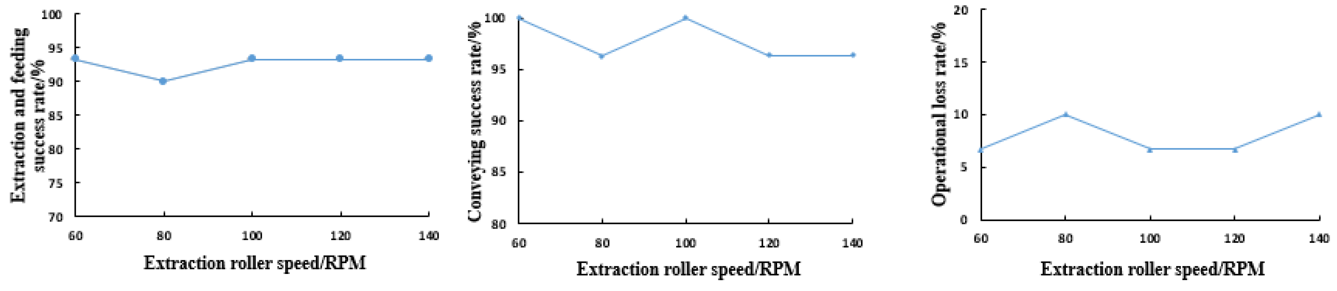
Single-factor experiment for extraction roller speed: During the experiment, the conveyor belt speed was set to 60 RPM, the root-clamping belt speed to 50 RPM, and the forward speed to 1 km·h−1. The extraction roller speed started at 60 RPM, with increments of 20 RPM for each experiment. A total of five experimental groups were conducted, with a maximum extraction roller speed of 140 RPM;
(2)
Single-factor experiment for conveyor belt speed: During the experiment, the extraction roller speed was set to 100 RPM and the forward speed to 1 km·h−1. The conveyor belt speed started at 40 RPM, with increments of 10 RPM for each experiment. A total of five experimental groups were conducted, with a maximum conveyor belt speed of 80 RPM;
(3)
Single-factor experiment for forward speed: During the experiment, the transport belt speed was set to 60 RPM, the root-clamping belt speed to 50 RPM, and the extraction roller speed to 100 RPM. The forward speed started at 0.8 km·h−1, with increments of 0.1 km·h−1 for each experiment. A total of five experimental groups were conducted, with a maximum forward speed of 1.2 km·h−1.

4.3.3. Experimental Results and Analysis for Cabbage

As shown in Figure 26, it can be observed that as the extraction roller speed increases, the extraction and feeding success rate does not change significantly and remains above 90%. This indicates that the extraction roller speed has little impact on the extraction and feeding process, and it also confirms that the extraction roller speed is set within a reasonable range. The conveying success rate similarly does not show obvious changes, remaining above 96% throughout, which implies that once the cabbage is successfully pulled and fed, its posture is generally maintained during the clamping and conveying process. The operational loss rate also does not vary significantly, with all values between 6.7% and 10%.
Thus, the single-factor experiment for the cabbage extraction roller speed demonstrates that as long as the extraction roller speed is set within a reasonable range, its effect on the overall harvesting performance of the universal harvesting platform is minimal.
As shown in Figure 27, it can be seen that as the conveyor belt speed increases, the cabbage extraction and feeding success rate initially increases rapidly and then gradually decreases. The rapid increase is due to the fact that, with the walking speed remaining constant, a slow conveyor belt speed causes blockage at the feeding inlet, resulting in most cabbages experiencing a change in orientation after being fed in. As the conveyor belt speed continues to increase, the conveying success rate slowly and continuously decreases. The main reason is that at higher speeds, the reliability of both the conveyor belt and the root-clamping belt—as well as their speed matching—declines, leading to some cabbages experiencing posture changes during transport. The operational loss rate initially decreases rapidly and then gradually increases, which is closely correlated with the extraction and feeding success rate. It is primarily influenced by cabbage blockage and the reliability of the clamping and conveying device.
Thus, the single-factor experiment for the conveyor belt speed shows that matching the conveyor belt speed and the forward speed has a significant impact on the harvesting performance of the universal harvesting platform. The operational loss rate for cabbage is closely related to the extraction success rate, and an increase in the conveyor belt speed negatively affects the reliability of the clamping and conveying device.
As shown in Figure 28, it can be seen that as the forward speed increases, the extraction and feeding success rate first increases slowly and then continuously decreases. At low forward speeds, due to the appropriate setting of the conveyor belt speed, the overall extraction and feeding success rate remains above 90%. However, as the forward speed increases further, the difference between the forward speed and the conveyor belt speed becomes larger, causing blockages and crowding at the feeding inlet. The mutual pushing among cabbages then results in changes in their posture, which gradually decreases the extraction and feeding success rate. As the forward speed increases, the conveying success rate first slightly decreases and then rebounds, remaining relatively stable overall. This indicates that the forward speed of the universal harvesting platform has little impact on the conveying success rate. However, as the forward speed increases, the operational loss rate first decreases slowly and then continuously rises; this is strictly related to the extraction and feeding success rate, mainly because cabbages that fail in the extraction and feeding stage are more likely to be damaged by the extraction roller and root-clamping belt.
Thus, the single-factor experiment for forward speed reveals that matching the conveyor belt speed and the forward speed has a very significant impact on the harvesting performance for cabbage, while the conveying success rate is not strongly correlated with the forward speed. The operational loss rate for cabbage is closely related to the extraction and feeding success rate.

5. Discussion

(1)
Study on matching the clamping device speed and the root-clamping device speed for regulating Chinese cabbage posture: In this study, the soil-trough harvesting experiment for Chinese cabbage relied solely on matching the forward speed with the conveyor belt speed to achieve optimal performance of the universal harvesting platform. However, the primary factor affecting the extraction success rate is the change in the posture of Chinese cabbage during the extraction process, which is a key challenge in the harvesting method that involves extraction followed by conveying and root-cutting. By matching the rotation speeds of the clamping device and the root-clamping device, the posture variation during the extraction process can be minimized, greatly improving the harvesting efficiency of the machine;
(2)
Determination of core parameters: The universal harvesting platform for cabbage and Chinese cabbage designed in this study features many adjustable parameters to achieve universality in harvesting. However, the soil-trough harvesting experiment revealed that having too many adjustable parameters increases the unreliability of the platform. Reducing the number of adjustable parameters can enhance the overall reliability of the platform;
(3)
Design of an adjustable root-cutting device: Due to various issues, the universal harvesting platform for cabbage and Chinese cabbage designed in this study does not include a root-cutting device. In future work, an adjustable root-cutting device that can be moved up and down could be designed. Its floating stroke should meet the root-cutting requirements for both cabbage and Chinese cabbage, thereby further enhancing the completeness of the platform;
(4)
Multi-factor optimization experiments for the root-clamping device: The designed root-clamping device incorporates an important root-clamping limiting function. That is, during installation, an angular difference is maintained between the clamping belt and the limit guide rail. As the clamping belt moves backward, it pulls down the lotus seats of the cabbage and Chinese cabbage, causing them to fall onto the limit guide rail. This mechanism addresses the issue of inconsistent optimal root-cutting positions after extraction, which can reduce the qualified root-cutting rate. However, due to time constraints, this aspect was not further explored in this current study. Future work may involve multi-factor optimization experiments to determine the optimal parameters for the root-clamping device.

6. Conclusions

(1)
In response to the problem that existing cabbage and Chinese cabbage harvesters can only harvest a single variety of vegetable and lack universality, a modular design was developed for a universal cabbage–Chinese cabbage harvesting platform. Based on common cabbage and Chinese cabbage varieties and main cultivation patterns in the Jiangsu–Zhejiang region of China, the harvesting platform can achieve simultaneous harvesting of both cabbage and Chinese cabbage by replacing components and adjusting parameters;
(2)
In response to the insufficient research on the extraction-first method for Chinese cabbage harvesting in China, a Y-shaped extraction device was designed to cooperate with the conveyor belt for the extraction process. The flexible conveyor belt can deform along the direction of the cabbage ball, increasing the contact area with the cabbage. This reduces the force per unit area, thereby minimizing damage during the extraction process. Additionally, a dual clamping method using both the clamping device and the root-clamping device was adopted. The posture of the cabbage can be adjusted by matching the speeds of the conveyor belt and the root-clamping belt, helping to reduce posture changes during the extraction stage and minimizing damage caused by these changes;
(3)
The results of the Chinese cabbage soil-trough harvesting experiment showed that when the forward speed was set to 1 km·h−1 and the conveyor belt speed was set to 60 RPM, the universal harvesting platform exhibited optimal overall performance. The extraction success rate was 86.7%, the clamping and conveying success rate was 92.3%, and the operational damage rate was 6.7%. For the cabbage soil-trough harvesting experiment, when the extraction roller speed was set to 100 RPM, the conveyor belt speed to 60 RPM, and the forward speed to 1 km·h−1, the best overall performance was achieved. The extraction and feeding success rate was 93.3%, the conveying success rate was 100%, and the operational loss rate was 6.7%.

Author Contributions

Conceptualization, Z.L., G.M. and H.M.; methodology, H.M. and G.M.; software, Z.L.; validation, Z.L., T.J., Z.Z. and G.M.; investigation, Z.L.; resources, Z.L. and Y.W.; data curation, Z.L. and J.C.; writing—original draft preparation, Z.L.; writing—review and editing, Z.L. and H.M.; visualization, C.L.; supervision, Z.L., L.S. and S.W.; project administration, Y.W. All authors have read and agreed to the published version of the manuscript.

Funding

This research was funded by the China Agriculture Research System (CARS-23-D03), a project funded by the Priority Academic Program Development of Jiangsu Higher Education Institutions (Jiangsu Education Department, Grant No. PAPD-2023-87) and the National Key Research and Development Program of China (Grant No. 2023YFD2001203).

Institutional Review Board Statement

Not applicable.

Data Availability Statement

The data presented in this study are available on request from the authors.

Conflicts of Interest

The authors declare no conflicts of interest.

References

  1. Chen, Y.S.; Liu, X.C. Development Report of China Vegetable Mechanization in 2009. J. Chin. Agric. Mech. 2020, 41, 46–53. (In Chinese) [Google Scholar] [CrossRef]
  2. Yang, J.H.; Fang, X.; Ma, L.X. Research Status and Direction of Knotting Vegetable Harvesting Machinery. J. Agric. Mech. Res. 2023, 45, 10–17. (In Chinese) [Google Scholar]
  3. Hansen, C.J. Harvesting Machine for Cabbage, or the Like. U.S. Patent 3827503, 6 August 1974. [Google Scholar]
  4. Lenker, D.H.; Nascimento, D.F.; Adrian, P.A. Apparatus for Harvesting Vegetable Heads. U.S. Patent 4136509, 30 January 1979. [Google Scholar]
  5. Chagnon, R.; Eng, P.; Charles, M.T. Development of a Cabbage harvester. In Proceedings of the 2004 ASAE/CSAE Annual International Meeting, Ottawa, ON, Canada, 1–4 August 2004. [Google Scholar]
  6. Zhang, J.; Cao, G.; Jin, Y.; Tong, W.; Zhao, Y.; Song, Z. Parameter Optimization and Testing of a Self-Propelled Combine Cabbage Harvester. Agriculture 2022, 12, 1610. [Google Scholar] [CrossRef]
  7. Liu, Z.; Wang, E.; Mao, H.; Zuo, Z.; Peng, H.; Zhao, M.; Yu, Y.; Li, Z. Design and Testing of an Electric Side-Mounted Cabbage Harvester. Agriculture 2024, 14, 1741. [Google Scholar] [CrossRef]
  8. Kanamitsu, M.; Kenji, Y. Development of Chinese cabbage harvester. JARQ 1996, 30, 35–41. [Google Scholar]
  9. Kim, H.; Yeongsoo, C. Pulling Performance of a Self-Propelled Chinese cabbage Harvester and Design of a Preprocessing Unit. J. Agric. Life Sci. 2020, 54, 99–108. [Google Scholar] [CrossRef]
  10. Yang, K.W. Development and Performance Test of Prototype Chinese Cabbage Harvester(I). J. Agric. Life Sci. 2022, 56, 113–123. [Google Scholar] [CrossRef]
  11. Zhang, J.; Wang, J. Design and experiment of crawler self-propelled single-row harvester for Chinese Cabbage. Trans. Chin. Soc. Agric. Mach. 2022, 53, 134–146. (In Chinese) [Google Scholar]
  12. Du, D.D. Research on Crawler Self-Propelled Cabbage Harvester Equipment and Development of Its Weighing System. Ph.D. Thesis, Zhejiang University, Hangzhou, China, 2017. (In Chinese). [Google Scholar]
  13. Yang, Y.T.; Cui, Z.C.; Gao, Q.S. Current Status and Development Recommendations for the Mechanized Production of Chinese Cabbage in China. Chin. Veg. 2020, 11, 9–16. (In Chinese) [Google Scholar]
  14. Zhang, J.F.; Xiao, H.R.; Cao, G.Q. Cabbage harvester header design and test. J. Chin. Agric. Mech. 2020, 41, 39–44. (In Chinese) [Google Scholar] [CrossRef]
  15. Yang, Y. Design and Research of the 4LZY-7 Rapeseed Combine Harvester. Master’s Thesis, Gansu Agricultural University, Lanzhou, China, 2019. (In Chinese). [Google Scholar]
  16. Guo, X.; Wang, S.; Chen, S.; Li, B.; Tang, Z.; Hu, Y. Impact of Structural Parameters on the Collision Characteristics and Coefficient of Restitution of Soybean Particles on Harvester’s Cleaning Screens. Agriculture 2024, 14, 1201. [Google Scholar] [CrossRef]
  17. Ma, Z.; Zhu, Y.; Li, J. Study on the performance of detection air duct and evaluation index of agricultural cleaning centrifugal fans. Biosyst. Eng. 2024, 239, 81–97. [Google Scholar] [CrossRef]
  18. Zhang, Q.; Fang, H.; Xu, G.; Niu, M.; Li, J. Experimental and Numerical Analysis of Straw Motion under the Action of an Anti-Blocking Mechanism for a No-Till Maize Planter. Agriculture 2024, 14, 1001. [Google Scholar] [CrossRef]
  19. Song, C.H.; Qu, G.Y.; Liu, Q.T. Effect of friction between spiral component and sugarcane on sugarcane lifting. J. Hunan Agric. Univ. (Nat. Sci.) 2012, 38, 330–332. (In Chinese) [Google Scholar] [CrossRef]
  20. Jia, H.W.; Wen, B.; Wang, X.F. Design and experiments of the electro-mechanical integrated measurement device for a grain friction coefficient. Trans. CSAE 2025, 41, 31–41. (In Chinese) [Google Scholar]
  21. Yuan, L.; Tang, Z.; Liu, S.; Wang, T.; Ding, Z. Design for Copying Grouser and Bionic Convex Hull Patterns on Track Surfaces of Crawler Combine Harvesters. Agriculture 2024, 14, 1079. [Google Scholar] [CrossRef]
  22. Wang, S.Y. Design and Experimental Research of Self-Propelled Cabbage Harvesting Test Platform. Master’s Thesis, Jiangsu University, Zhenjiang, China, 2019. (In Chinese). [Google Scholar]
  23. Kou, T.H.; Yang, Y.; Wang, C. Analysis of clamping force and experimental study of mechanical characteristics of onion. J. Chin. Agric. Mech. 2020, 42, 174–180. (In Chinese) [Google Scholar]
  24. Zhou, L.L. Research on the Key Technologies of Low Damage and Orderly Harvest for Spinach with Root. Ph.D. Thesis, Shandong Agricultural University, Taian, China, 2022. (In Chinese). [Google Scholar]
  25. Zhang, J. Research on Physical and Mechanical Properties of Headed Chinese Cabbage and Its Crawler Self-Propelled Harvesting Machine. Ph.D. Thesis, Zhejiang University, Hangzhou, China, 2022. (In Chinese). [Google Scholar]
  26. Cao, Y.; Yu, Y.; Tang, Z.; Zhao, Y.; Gu, X.; Liu, S.; Chen, S. Multi-Tooth Cutting Method and Bionic Cutter Design for Broccoli Xylem (Brassica oleracea L. var. Italica Plenck). Agriculture 2023, 13, 1267. [Google Scholar] [CrossRef]
  27. Shi, Y.Y.; Zhang, Y.N.; Wang, X.C. Design of Orderly Harvester in Stems-leafy Vegetables Based on Pro/E. J. Chin. Agric. Mech. 2017, 39, 139–143. (In Chinese) [Google Scholar]
  28. Xu, H.G.; Zhang, C.X.; Zhang, X.J. Development and Application of Corn Harvester for Hilly Area. Trans. CSAE 2021, 11, 102–107. (In Chinese) [Google Scholar]
  29. Liu, J.; Liang, J.; Zhao, S.; Jiang, Y.; Wang, J.; Jin, Y. Design of a Virtual Multi-Interaction Operation System for Hand–Eye Coordination of Grape Harvesting Robots. Agronomy 2023, 13, 829. [Google Scholar] [CrossRef]
  30. Gao, Y.; Hu, Y.; Yang, Y.; Feng, K.; Han, X.; Li, P.; Zhu, Y.; Song, Q. Optimization of Operating Parameters for Straw Returning Machine Based on Vibration Characteristic Analysis. Agronomy 2024, 14, 2388. [Google Scholar] [CrossRef]
  31. GB/Z 26582-2011; Production Technical Practice for Cabbage. China National GB Standard Research: Shenzhen, China, 2011.
  32. JB/T 6276-2007; Test Method for Sugar Beet Harvesting Machinery. Ministry of Machinery and Electronics Industry of the People’s Republic of China: Beijing, China, 2007.
Disclaimer/Publisher’s Note: The statements, opinions and data contained in all publications are solely those of the individual aut`hor(s) and contributor(s) and not of MDPI and/or the editor(s) MDPI and/or the editor(s) disclaim responsibility for any injury to people or property resulting from any ideas, methods, instructions or products referred to in the content.
Figure 1. Cabbage and Chinese cabbage planting ridge structure diagram: (p) plant spacing; (l) ridge distance; (s) row spacing; (w) ridge width; (h) ridge height.
Agriculture 15 00935 g001
Figure 2. Schematic diagram of cabbage harvesting mechanism: (1) control unit; (2) clamping and conveying device; (3) harvesting-unit frame; (4) leaf-stripping wheel; (5) extraction rollers.
Agriculture 15 00935 g002
Figure 3. Schematic diagram of Chinese cabbage harvesting mechanism: (6) Y-type root extraction device; (7) feeding guide device.
Agriculture 15 00935 g003
Figure 4. Schematic diagram of the leaf-stripping wheel structure: (1) mounting plate; (2) mounting frame; (3) blades; (4) motor; (5) wheel.
Agriculture 15 00935 g004
Figure 5. Motion trajectory of the leaf-stripping wheel.
Agriculture 15 00935 g005
Figure 6. Schematic diagram of the leaf-stripping wheel in operation.
Agriculture 15 00935 g006
Figure 7. Schematic of the extraction roller structure: (1) motor; (2) frame mounting plate; (3) coupling; (4) motor mounting plate; (5) conical roller mounting plate; (6) conical roller.
Agriculture 15 00935 g007
Figure 8. Kinematic analysis of the extraction roller.
Agriculture 15 00935 g008
Figure 9. Kinematic analysis of cabbage.
Agriculture 15 00935 g009
Figure 10. Schematic diagram of the Y-type extraction device structure: (1) clamping roller; (2) rotating shaft; (3) Y-type mounting plate; (4) clamping shaft.
Agriculture 15 00935 g010
Figure 11. Schematic diagram of the Chinese cabbage extraction process.
Agriculture 15 00935 g011
Figure 12. Force analysis of Chinese cabbage extraction.
Agriculture 15 00935 g012
Figure 13. Schematic diagram of the clamping device structure: (1) driving wheel; (2) driving motor; (3) outer tensioning wheel; (4) harvesting-unit frame; (5) tensioning device; (6) conveyor belt; (7) driven wheel.
Agriculture 15 00935 g013
Figure 14. Schematic diagram of the root-clamping-device structure: (1) driving wheel; (2) driving motor; (3) root-clamping-device mounting plate; (4) root-clamping-device frame; (5) tensioning device; (6) limiting device; (7) root-clamping belt; (8) driven wheel.
Agriculture 15 00935 g014
Figure 15. Force analysis during the Chinese cabbage conveying process.
Agriculture 15 00935 g015
Figure 16. Motion analysis of the Chinese cabbage conveying process.
Agriculture 15 00935 g016
Figure 17. Schematic diagram of the experimental platform structure: (1) chassis frame; (2) drive unit; (3) control unit; (4) power converter; (5) drive axle; (6) stepper motor.
Agriculture 15 00935 g017
Figure 18. Human–machine interface panel of the experimental platform control system.
Agriculture 15 00935 g018
Figure 19. Overall structure of the root-clamping device: (1) mounting base; (2) aluminum profile; (3) clamp.
Agriculture 15 00935 g019
Figure 20. Components of the force measurement device: (a) extraction force measurement platform; (b) force measurement system.
Agriculture 15 00935 g020
Figure 21. Force analysis of the root of cabbage and Chinese cabbage.
Agriculture 15 00935 g021
Figure 22. Chinese cabbage soil-trough harvesting experiment.
Agriculture 15 00935 g022
Figure 23. Graph of single-factor experimental results for the forward speed of Chinese cabbage.
Agriculture 15 00935 g023
Figure 24. Graph of single-factor experimental results for the conveyor belt speed for Chinese cabbage.
Agriculture 15 00935 g024
Figure 25. Cabbage soil-trough harvesting experiment.
Agriculture 15 00935 g025
Figure 26. Graph of single-factor experimental results of the extraction roller speed for cabbage.
Agriculture 15 00935 g026
Figure 27. Graph of single-factor experimental results of the conveyor belt speed for cabbage.
Agriculture 15 00935 g027
Figure 28. Graph of single-factor experimental results of the forward speed for cabbage.
Agriculture 15 00935 g028
Table 1. Physical characteristic parameters of common cabbage varieties.
VarietyPlant Height
(mm)
Root
Length (mm)
Head Diameter
(mm)
Head Weight
(kg)
Total Weight
(kg)
Zhegan 85318 ± 25.6122 ± 22.8210 ± 18.21.88 ± 0.262.45 ± 0.28
Aoqina232 ± 39.9198 ± 22.2243 ± 36.13.82 ± 0.354.02 ± 0.77
Chunqiu Wang150 ± 14.5 135 ± 12.6 1.28 ± 0.15
Lanzhou Bao190 ± 19.5 143 ± 13.6 1.16 ± 0.12
Chunfeng300 ± 25.6 130 ± 12.5 1.45 ± 0.21
Table 2. Physical characteristic parameters of common Chinese cabbage varieties.
VarietyPlant Height
(mm)
Root
Length (mm)
Head Diameter
(mm)
Head Weight
(kg)
Total
Weight (kg)
Zaoshu 5300~32075~92140~1801~1.5
Huangxin290 ± 19.2138 ± 24.7183 ± 17.4 2.34 ± 0.39
Xiayang287 ± 6.1158 ± 18.8185 ± 19.8 3.19 ± 0.78
Table 3. Parameters of the universal harvesting platform.
Parameter NameUnitValue (Range)
Suitable cabbage and Chinese cabbage head diametermm50~280
Number of harvesting rowsrow1
Overall dimensions (L × W × H)mm2920 × 1380 × 1140
Conveyor belt speedRPM0~300
Root-clamping belt speedRPM0~300
Leaf-stripping wheel speedRPM0~100
Extraction roller speedRPM0~500
Platform angle with ground°5~30
Table 4. Physical property parameters of Chinese cabbage.
Statistical IndicatorTotal
Mass
(kg)
Spherical
Diameter
(mm)
Plant Height
(mm)
Root
Diameter
(mm)
Root
Length (mm)
Minimum1.5715525416.3585
Maximum2.9831532622.46201
Average2.43186.4292.119.72138.4
Standard Deviation0.4444.2620.581.9427.81
Coefficient of Variation0.180.240.070.110.22
Table 5. Physical properties parameters of cabbage.
Statistical IndicatorTotal
Weight
(kg)
Head
Diameter
(mm)
Plant
Height
(mm)
Root
Diameter
(mm)
Root
Length
(mm)
Minimum2.1915225416.3585
Maximum3.7424932622.46201
Average2.71194.5292.0619.72138.41
Standard Deviation0.4244.2620.581.9427.8
Coefficient of Variation0.160.240.070.10.2
Disclaimer/Publisher’s Note: The statements, opinions and data contained in all publications are solely those of the individual author(s) and contributor(s) and not of MDPI and/or the editor(s). MDPI and/or the editor(s) disclaim responsibility for any injury to people or property resulting from any ideas, methods, instructions or products referred to in the content.

