Article

Biomimetic Structural Design for Reducing the Adhesion Between Wet Rice Leaves and Metal Surfaces

1
School of Mechanical Engineering, Jiangsu University, Zhenjiang 212013, China
2
School of Agricultural Engineering, Jiangsu University, Zhenjiang 212013, China
3
Key Laboratory of Modern Agricultural Equipment and Technology, Ministry of Education, Jiangsu University, Zhenjiang 212013, China
*
Author to whom correspondence should be addressed.
Agriculture 2025, 15(9), 921; https://doi.org/10.3390/agriculture15090921
Submission received: 12 March 2025 / Revised: 5 April 2025 / Accepted: 9 April 2025 / Published: 23 April 2025
(This article belongs to the Section Agricultural Technology)

Abstract

:
Adhesion behavior between wet rice leaves and metal surfaces exacerbates the difficulty in separating and removing grains in the cleaning device. Reducing the adhesion between the wet rice leaves and the cleaning device is an important factor in improving the harvesting performance of rice combine harvesters. This paper investigates the possibility of reducing the adhesion between them. By studying the liquid shape characteristics between the removed grains and the surface, it was found that the adhesion force between the leaf and the surface is greatest when additional pressure is present. Based on biomimetic principles and the convex hull structure of a dung beetle’s head, a convex hull structure for the metal surface was designed to balance the atmospheric pressure on both sides of the leaf in order to eliminate additional pressure. Using the liquid bridge model between a spherical and a flat surface, a liquid bridge model for the leaf and convex hull surface was established. By optimizing the minimum liquid bridge force, the convex hull radius and distance were determined to be 2.47 mm and 1.38 mm, respectively. Contact and collision experiments verified that the convex hull surface is more effective in reducing the adhesion of moist leaves, providing a reference for future research on the cleaning methods of moist rice grains.

1. Introduction

Rice, as one of the main food products in China, has the largest planting area and total output, with an annual planting area of more than 30 million hectares [1,2]. The promotion and application of rice combine harvesters has provided an effective way to improve food production efficiency and ensure food supply and demand in China [3,4,5]. However, there are still some difficulties in the actual use of rice combine harvesters. Frequent rainy weather in the middle and lower reaches of the Yangtze River is extremely unfavorable to the mechanized rice harvest, and the rice yield is seriously damaged [6,7]. It is difficult for the cleaning device of rice combine harvesters to separate the broken rice leaves and stalks from the wet rice effluent, which is one of the important factors affecting the low efficiency of rice harvest [8,9]. As shown in Figure 1 and Figure 2, there is more free water on the surface of wet rice. When the extruded grains, broken rice leaves and broken stalks are in contact with each other, the surface liquid will produce liquid bridge phenomenon due to the action of surface tension, resulting in mutual adhesion of the extruded products, mostly in a clad-like structure, low threshing rate and high impurity content [10,11,12]. In addition, the liquid bridge force generated by the liquid bridge also causes the broken rice leaves and stems with high moisture content to adhere to the metal wall of the cleaning device, which is difficult to be excluded by the gas field, blocking the screen hole, resulting in the difficulty of threshing [13,14,15]. Fu Jun and Cheng Chao et al. conducted a comparative experiment on two kinds of rice threshing mixtures to obtain the influence of moisture content on the adhesion characteristics of the threshing mixtures [16]. Further, they used polyvinylidene difluoride piezoelectric film as the sensitive element and designed a wet adhesion sensor for rice stem collision, analyzing the motion patterns of the rice stem during the adhesion and detachment processes [15]. However, the research on the liquid bridge effect between particles and the surface of devices is relatively scarce both at home and abroad.
In order to solve the adhesion problem, it is necessary to understand the changing law of liquid bridge force. Theoretical analysis of liquid bridge interaction between spheres has been studied, including the change law of liquid bridge force during the stretching process of smooth surface spherical particles [17,18], the energy required for the fracture of liquid bridge between particles of equal diameter and the law of adhesion force during the stretching process [19,20], and the change in liquid bridge force between particles of different diameters and the calculation model of distance between breaking points [21]. It provides the basis for destroying or weakening the liquid bridge force. Early measurement of liquid bridge force mainly relied on differential balance [22] and cantilever beam measurement technology [23,24]. With the progress of science and technology, domestic and foreign scholars have applied the rigidity testing machine to the liquid bridge tensile experiment, measured the change law of the liquid bridge tensile force in the three-particle system [25,26], and further improved the force and shape change law of the liquid bridge between particles of equal diameter [27]. In the field of liquid bridge theory and numerical simulation, the Young–Laplace equation proposed by Thomas Young and Pierre-Simon Laplace is widely used. Liu Jianlin et al. [28] derived the governing equation of the liquid bridge based on the principle of minimum potential energy and solved the Laplace equation to obtain the shape of the liquid bridge. Wang Xuewei et al. [29] studied the fracture distance of the liquid bridge between plates under the action of gravity by combining experiments and numerical simulation. The adhesion between leaves and the wall is the most serious in the threshing residue of rice. The study of the Young–Laplace equation and the liquid bridge effect between plates provides a reference for reducing the adhesion between wet rice leaves and the metal wall [30,31,32,33].
The adhesion of wet rice leaves was also related to metal surface hydrophobicity. The traditional contact angle evaluation method for material hydrophobicity is affected by droplet volume and surface position, and the evaluation results are not accurate [34,35]. Bionics scholars refer to the hydrophobic surface of plants such as lotus leaves, and sunflowers, and develop new superhydrophobic materials with similar properties [36,37,38,39]. These materials can reduce stain adhesion, prevent water vapor condensation into fog, and realize oil–water separation and other functions that existing materials do not have, and have attracted wide attention [40,41]. With the in-depth study of hydrophobic materials, scholars have found that micro- and nano-level composite structures are crucial to achieve super-hydrophobic properties [42]. Sharifi et al. [43] applied plasma spraying technology to replicate the micro-raised structure of lotus leaf on the surface of stainless steel, and successfully obtained hydrophobic properties. Yang et al. [44] simulated the micron-level structure of the surface of sophora japonicum by 3D printing technology, and sprayed nano-level coating on the surface, which also achieved the super hydrophobic effect. However, in the production of spraying technology, the equipment requirements are high, the quantification is difficult, and the preparation process is complicated, all of which limit the application of hydrophobic structures in the engineering field to a certain extent [45,46]. In addition, at the microscopic level, the space between the nanocomposite structures increases the surface roughness of the object, and the air can form a stable air cushion on the surface of the structure to prevent water droplets from penetrating, thus achieving the superhydrophobic characteristics of the surface. Although the air layer helps to improve the stability of the hydrophobic effect [47], the limited volume of the air layer limits the persistence of the hydrophobic effect [48]. In addition to imitating the microstructure of organisms, researchers have also tried to copy the macroscopic structure of natural objects to prepare hydrophobic surface materials beyond different sizes [49,50,51]. Compared with the micro-level hydrophobic imitation design, the macro hydrophobic surface can capture more air due to its larger size, reducing the contact range between droplets and the surface of the object, and thus maintaining the stability of the hydrophobic performance. Therefore, using the principle of bionics, changing the macroscopic structure of the wall and designing the metal surface that can stably exist the air layer are of great significance to reduce the adhesion effect between the wet rice leaves and the wall of the cleaning device.
In this study, the feasibility of reducing the adhesion of wet rice leaves to the metal wall of the cleaning device was analyzed. The specific analysis process is as follows: By studying the shape characteristics of the liquid between the wet rice leaves and the wall, we analyzed the influence of the additional pressure on the adhesion between them. From the angle of reducing additional pressure and increasing air layer, the feasibility of adhesion reduction is determined theoretically. The metal wall is modified into convex hull structure by the bionics method. According to the liquid bridge model between the spherical surface and the plane, the liquid bridge force model of the leaf and the convex hull surface is drawn, and the radius and spacing of the convex surface are further improved. Then, the experiments of contact and impact have confirmed that the convex surface can effectively reduce the adhesion of wet rice leaves. This study provides a reference for the subsequent research on cleaning methods of wet rice straw and the application of hydrophobic structures in the cleaning devices.

2. Materials and Methods

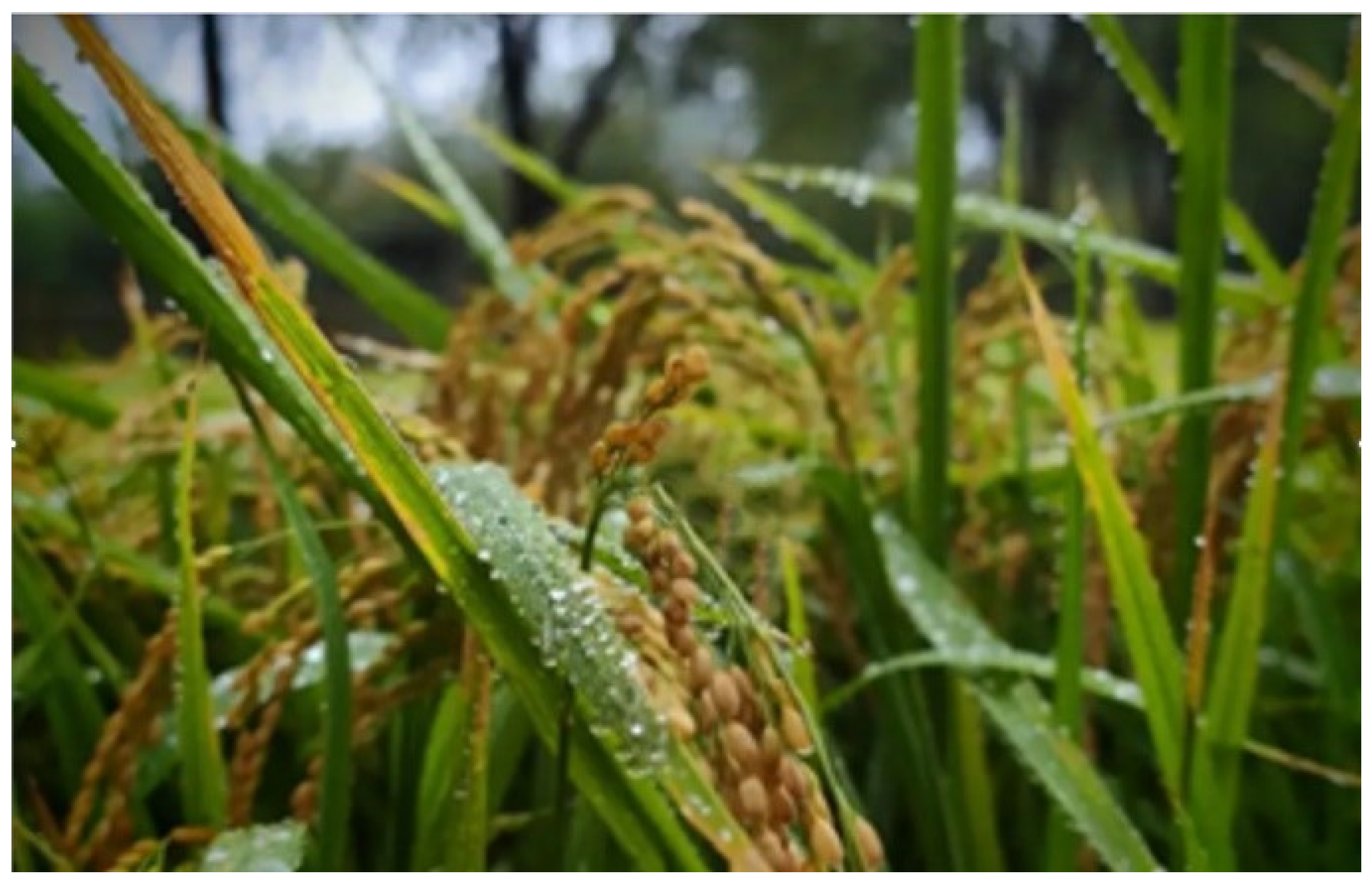
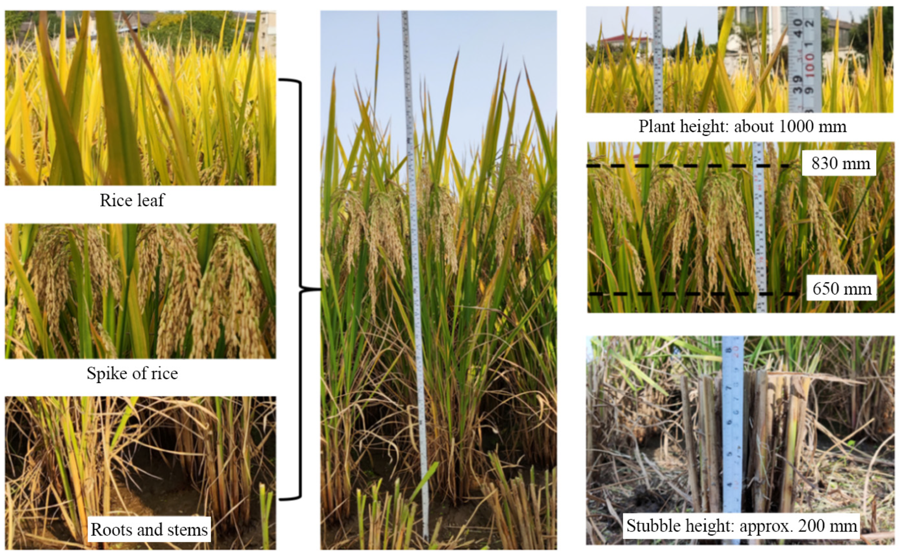
2.1. Basic Characters of Y-Liangyou Rice Plant

In this study, mature Y-Liangyou rice was taken as the experimental material. The rice was taken from the farmland of Xinfeng Town, Dantu District, Zhenjiang City, Jiangsu Province, and its basic characteristics were shown in Figure 3. The rice plants above the ground were approximately 1000 mm tall, with 25 to 28 tillers per plant, and approximately 16 rice leaves on the main stem, with a width of 1.5 to 2.5 mm.
Y-Liangyou rice is widely cultivated in Jiangsu, Zhejiang and Anhui areas, so it has certain universality for research. The physical property parameters of Y-Liangyou No. 1 and No. 2 are shown in Table 1.

2.2. Design of the Adhesion-Reducing Surface Structure of Cleaning Device

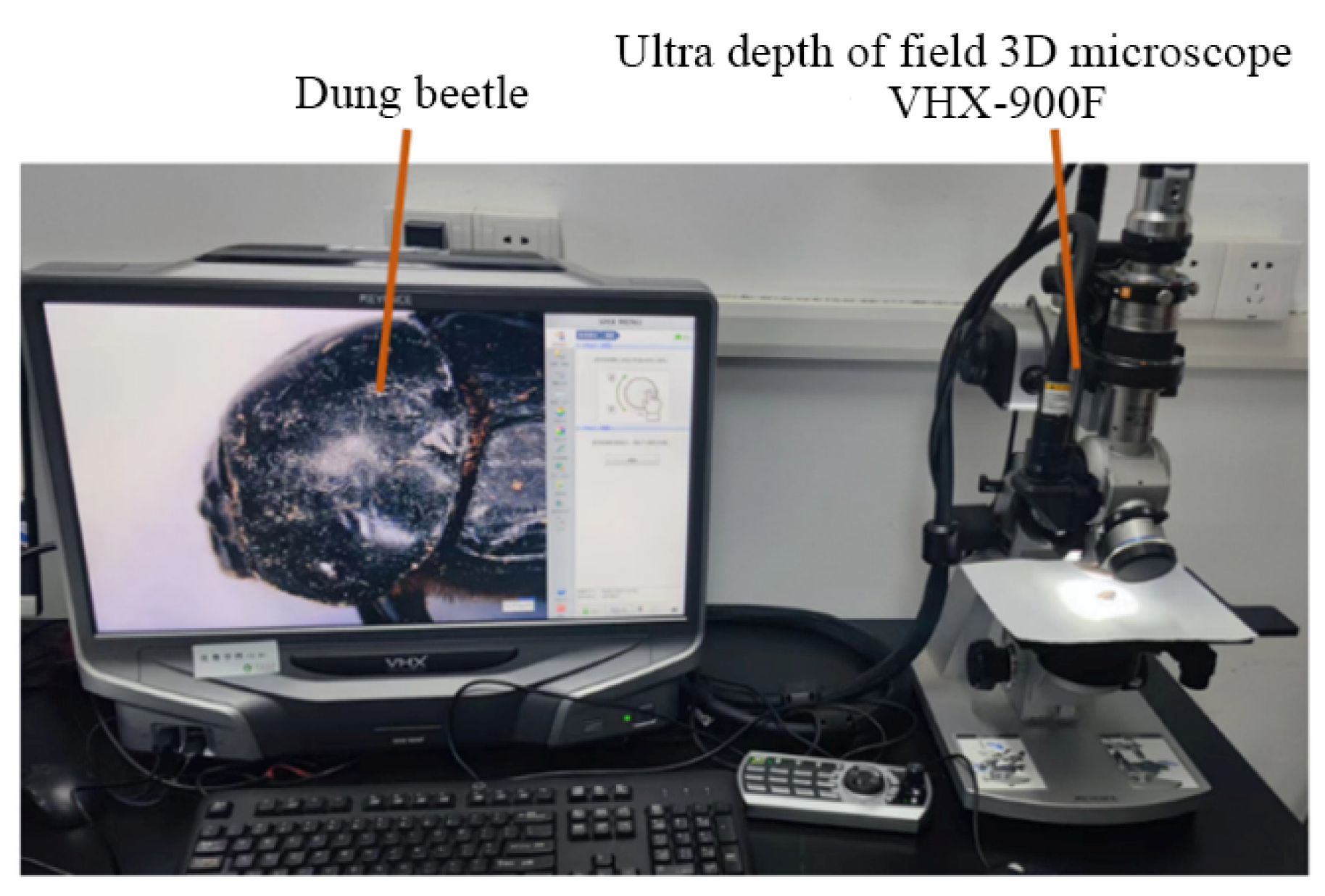
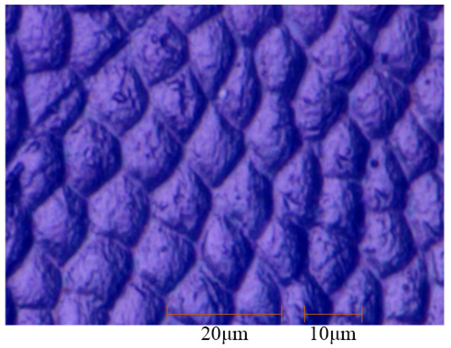
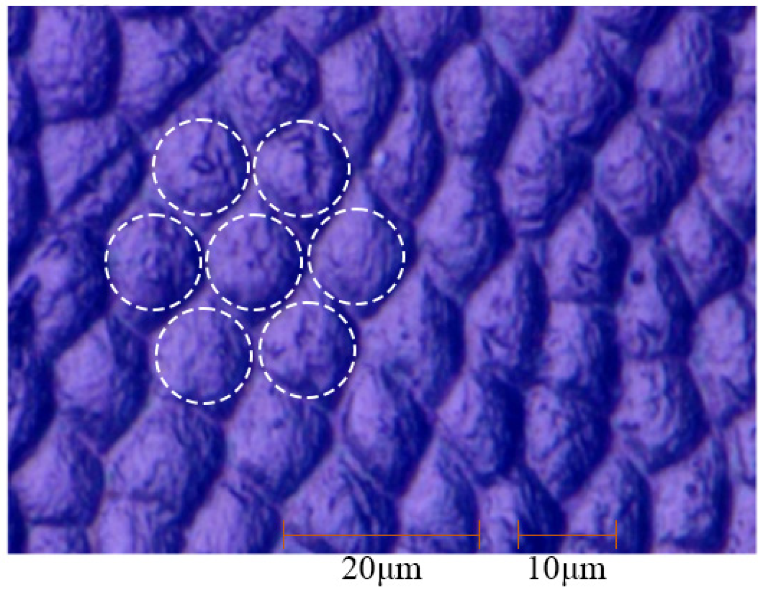
2.2.1. Extraction of the Surface Morphology of Dung Beetle

In order to reduce the adhesion effect between the wet rice leaves and the cleaning device. In this study, the surface structure of the cleaning device wall was optimized. The surface structure can be divided into microscopic and macroscopic types. During the operation of the cleaning device, the rice extruded material will continuously collide and friction with the wall of the internal structure of the device. Under this continuous action, the microscopic surface structure is easily destroyed and it is difficult to maintain the original state stably for a long time. In view of this, it is more suitable to designing macroscopic surface structures from the perspective of adapting to the working environment and running state of the cleaning device.
Bionics scholars often use bionics research methods to explore the principles and laws behind the unique structure of organisms, and translate these findings into practical applications to solve the technical problems faced. According to the related research of surface structure bionics, many biological surfaces have structural characteristics that effectively reduce the contact with solid materials. A surface can be considered a non-smooth surface when there are regions causing non-smooth effects in at least one direction. Based on the adhesion reduction characteristics of the non-smooth structure on the surface of organisms, this paper takes the non-smooth body shape of dung beetle as the research object.
Dung beetles, medium to large insects usually dark brown, belong to the Coleoptera Scarab family with over 20,000 known species, are widely distributed except in Antarctica. Despite the crushing of soil and friction with rough sand and gravel, dung beetles maintain a smooth and clean surface. This characteristic, which shows excellent adhesion reduction on soil contact, makes dung beetles an ideal target for this study. As shown in Figure 4, the dung beetles in this study were collected from the edge of a forest in Nanyang, Henan Province, China in early summer of 2024. And the ultra-depth-of-field three-dimensional microscope (Keyence, Osaka, Japan) is VHX-900F with a 1/1.8-inch CMOS image sensor (Keyence, Osaka, Japan). And the observable image size has a pixel resolution of 1600 (H) × 1200 (V). It can clearly present the morphological feature images of the surface areas of the dung beetle’s head and back by automatically adjusting the focal length.
The surface of the back of dung beetle was enlarged 500 times through a microscope, as shown in Figure 5. It was found that the convex hull on the back of dung beetle showed a micron-scale rule. The shape of the convex hull was similar to equilateral polygon, which was closely connected and staggered. The center of each convex hull was higher, and the edge was lower. Most of them are curved borders. The radial dimension of the convex hull is approximately 10 microns, the center distance between the two convex hull is also approximately 10 microns, and there is a large amount of space between the connected convex hull.

2.2.2. Biomimetic Surface Structure Design

The dorsal convex hull of dung beetle is high in the middle and low around the periphery, and the edge line is approximately regular polygon. Therefore, by softening the edge lines of the convex hull and simplifying the irregular convex hull into a semi-sphere and arranging it on the metal wall, the preliminary structure of the bionic surface can be obtained. The contact situation between the convex hulls and the wet rice leaves is shown in Figure 6. The liquid bridges are concentrated at the top of the convex hulls, and there are gaps between the rice leaves and the metal plane.

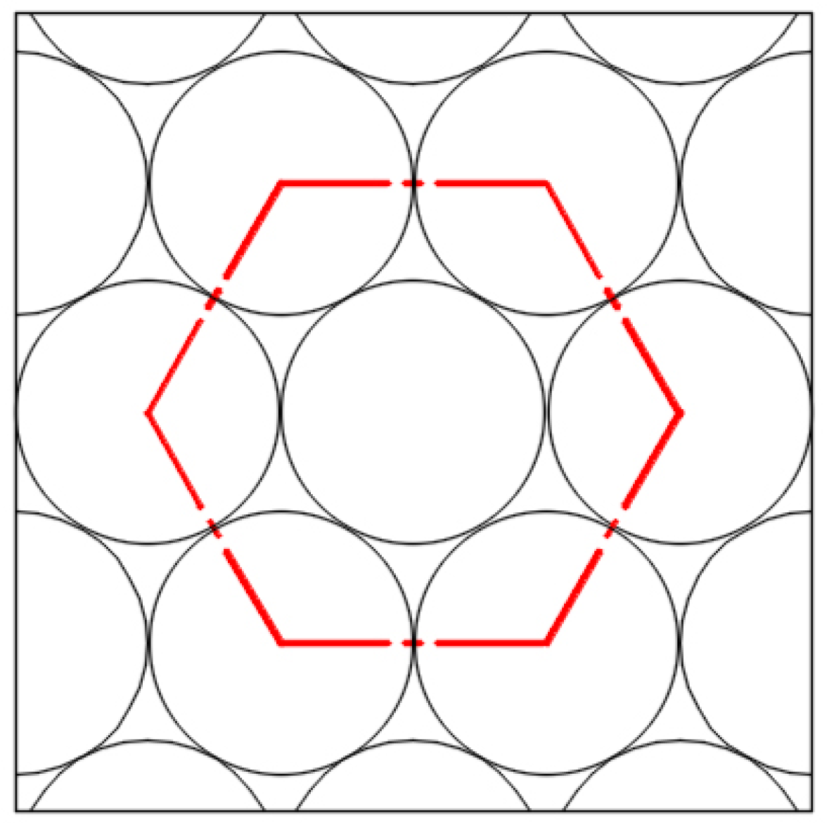
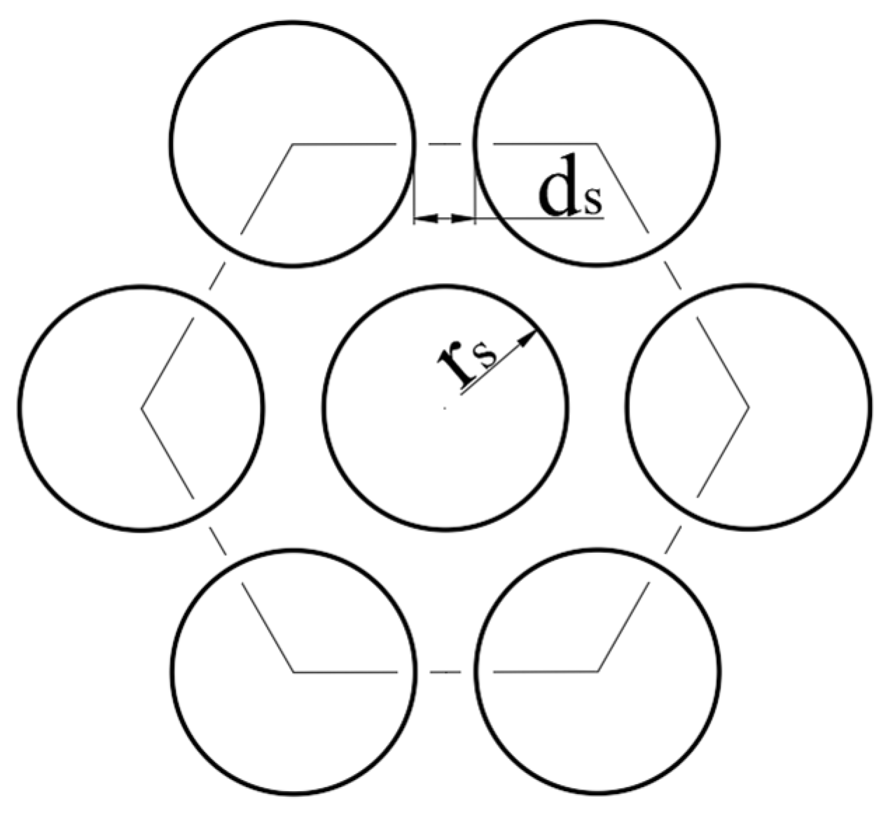
2.2.3. Convex Hull Structure Arrangement Design

The efficiency, simplicity and predictability of orderly arrangement are applicable to many fields. From the macroscopic scale of the dynamic movement of stars to the microscopic scale of the arrangement of atoms in crystals, they all show the ordered arrangement at different levels. In the ordered arrangement system, the laws formed by a single element or a group of elements can constitute the whole law system. Therefore, the convex hull arrangement on the metal wall is simplified to the ordered arrangement of two-dimensional planar medium diameter circles, which are mainly divided into two types of quadrangular close packing and hexagonal close packing, as shown in Figure 7 and Figure 8. The arrangement of hexagonal close packing is denser and the voidage is lower.
As shown in Figure 9, the white curved contour fitted by the convex hull on the surface of dung beetle is closer to the hexagonal close packing arrangement, with the convex hull densely arranged, with approximately six convex hull surrounded by each convex hull. As shown in Figure 10, under the hexagonal close packing arrangement, the convex hull radius rs and convex hull spacing ds can be determined, and the number of convex hull per unit area can be calculated according to Equation (1).
β = 2 3 3 2 r s + d s 2

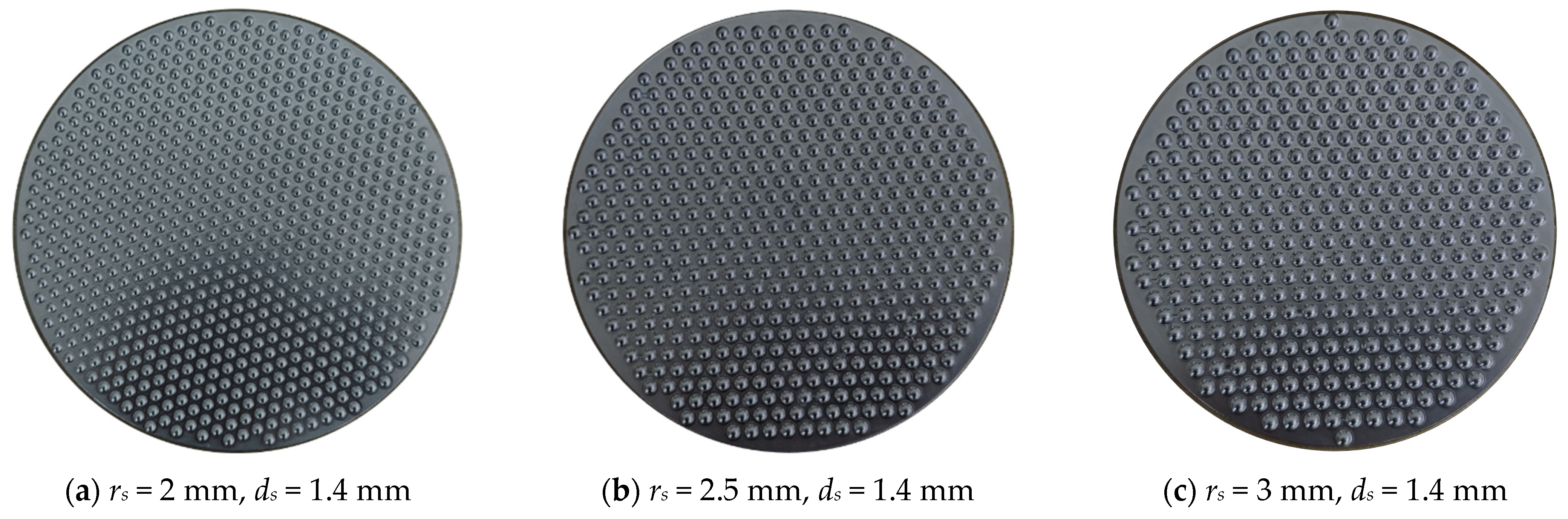
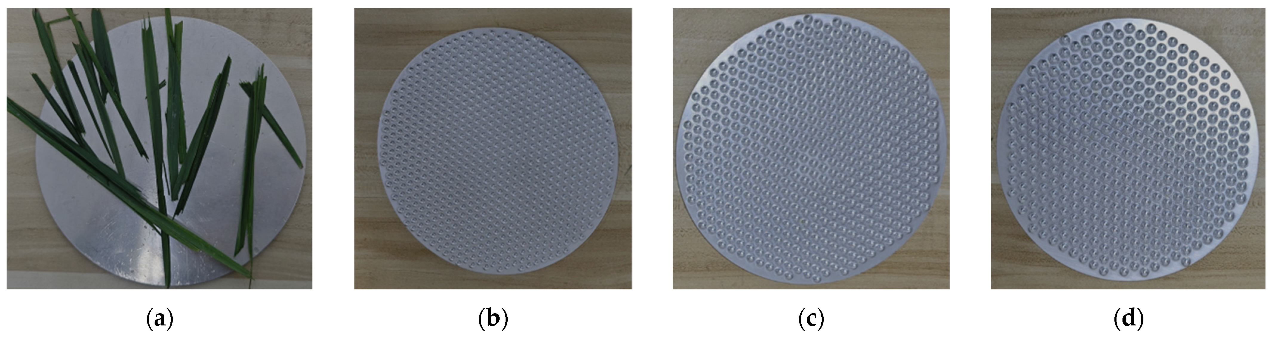
2.2.4. Bionic Convex Hull Metal Templates

As shown in Figure 11, three bionic convex hull metal templates were designed by the bionic method. The convex hull structure on the wall is milled, and the back of the template is a smooth plane. The convex hull radius on the surface of the three templates is 2 mm, 2.5 mm and 3 mm, the spacing between the convex hull is 1.4 mm, and the diameter of the template is 300 mm.

2.3. The Establishment of the Mathematical Model

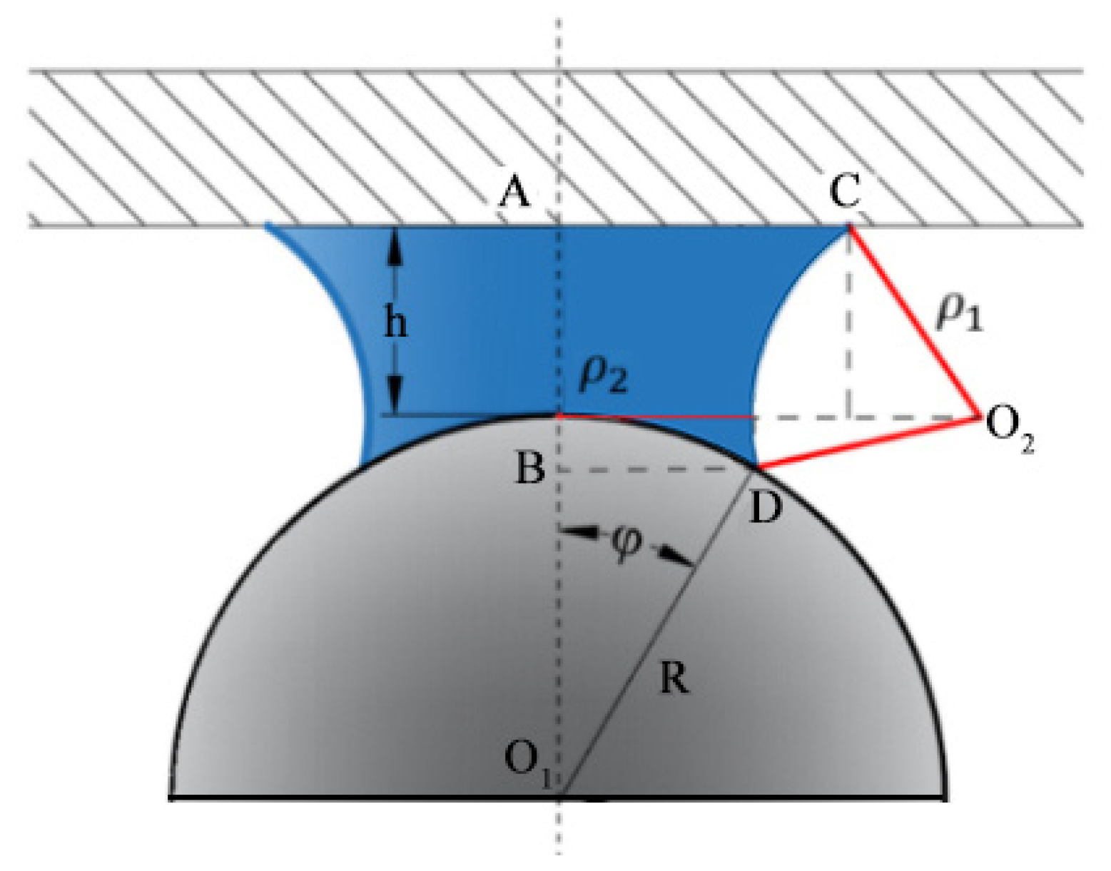
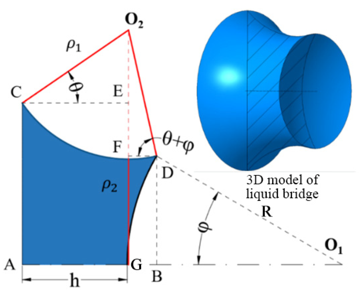
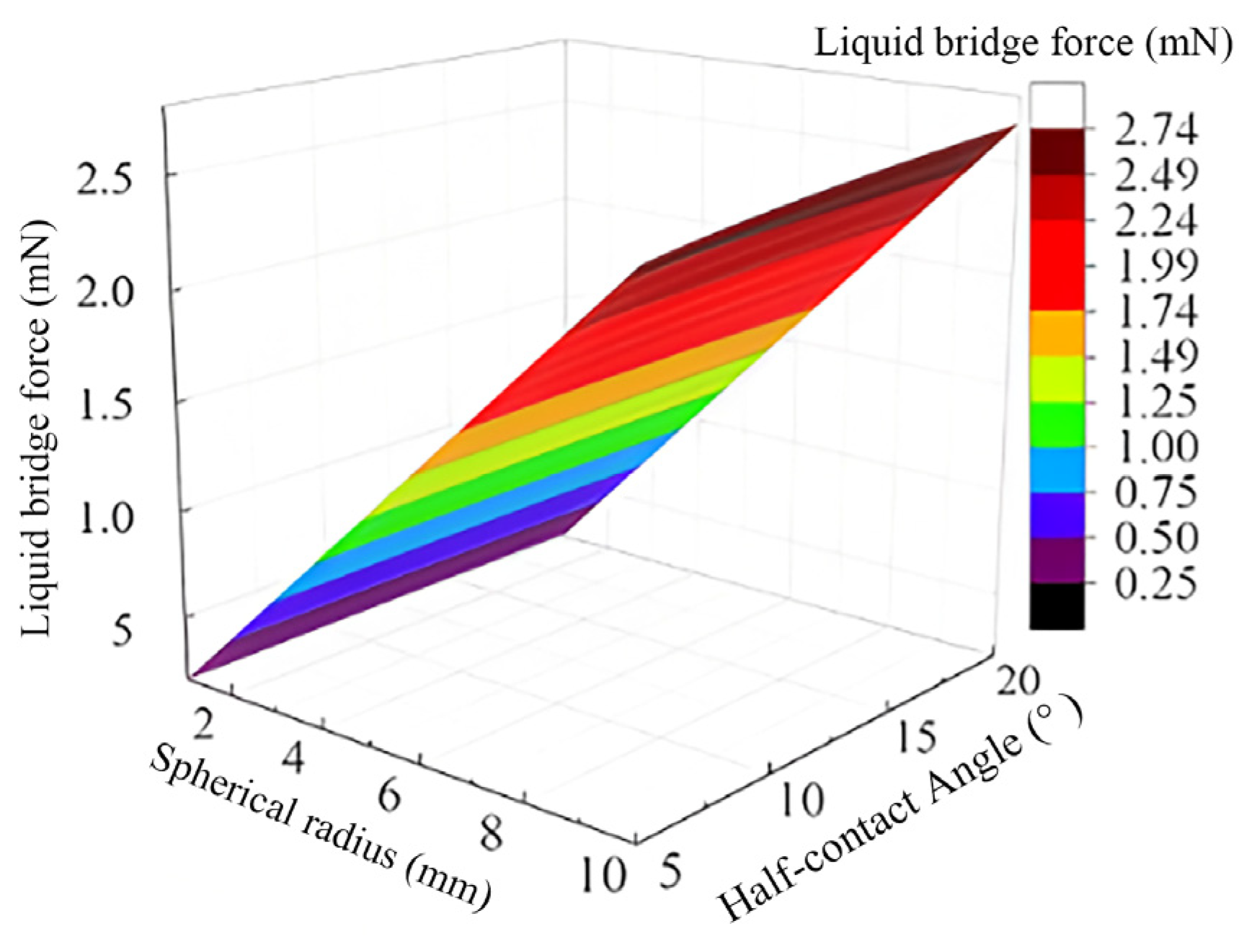
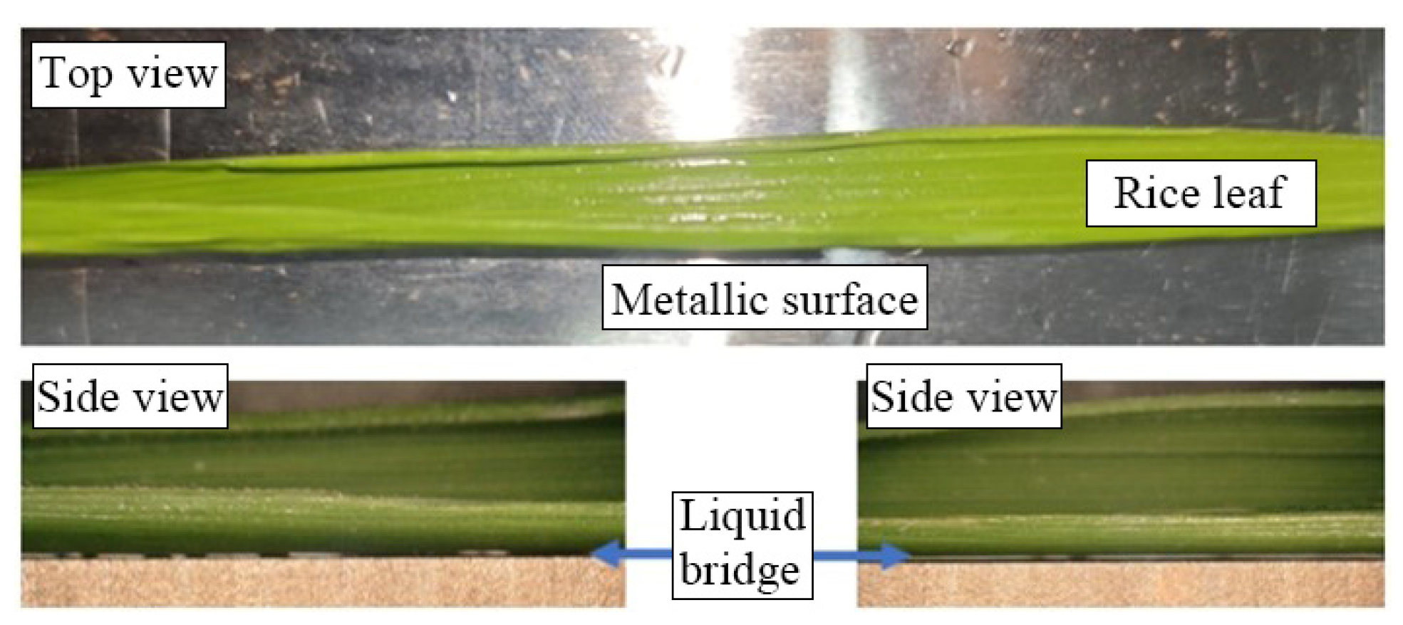
2.3.1. Establishment of the Liquid Bridge Model Between Sphere and Plane

The shape of the liquid bridge between the sphere and the plane is similar to an inverted internal concave and convex platform. According to Hotta K. and Fisher [52,53], the radial profile of the gas–liquid interface was treated as an arc, and the simplified liquid bridge model was obtained, as shown in Figure 12. Ignoring the influence of gravity on the shape of the liquid bridge, the pressure difference at the gas–liquid interface of the liquid bridge can be described by the Young–Laplace equation, as shown in Equation (2).
ρ = γ 1 ρ 1 + 1 ρ 2
As shown in Figure 13, according to the marked geometric parameters of the liquid bridge, it can be obtained that line segment AB is equal to the sum of line segments CE and DF. So, the length of line segment AB can be calculated by Equation (3), and the calculation Equation (4) of ρ1 can be further derived. Based on the geometric relationship shown in Figure 13, ρ2 can be calculated as shown in Equation (5), and the length of line segment O2G (denoted as a) can also be calculated as shown in Equation (6).
A B ¯ = C E ¯ + D F ¯ = R 1 cos φ + h = ρ 1 cos φ + 1
ρ 1 = R 1 cos φ + h cos φ + 1
ρ 2 = R sin φ ρ 1 1 sin φ + θ
O 2 G ¯ = a = ρ 1 sin φ + θ + R sin φ
As shown in the 3D model of the liquid bridge in Figure 13, the volume V of the liquid bridge can be obtained by subtracting the volume V2 (formed by the arc segment DG rotating around the central axis AO1) from the volume V1 (formed by the arc segment CD rotating around the central axis AO1), as shown in Equation (7).
V = V 1 V 2 = π a 2 + ρ 1 2 ρ 1 c o s φ + θ + c o s θ 1 3 ρ 1 3 c o s 3 φ + θ + c o s 3 θ a ρ 1 2 s i n φ + θ c o s φ + θ + s i n θ c o s θ + a ρ 1 2 φ + 2 θ π π 3 2 - 3 c o s φ + c o s 3 φ R 3
In MATLAB 2022, the mathematical model of the liquid bridge volume is established, and the influence of spherical radius and half-contact angle on the liquid bridge volume is analyzed. The spherical radius and half-contact angle were taken as variables, with the radius ranging from 1 to 10 mm and the half-contact angle ranging from 5 to 30°. The liquid bridge volume was calculated with certain increments, respectively, and the results were drawn into a three-dimensional surface as shown in Figure 14. With the increase in spherical radius and half-contact angle, the volume of liquid bridge also increases, and the influence of the two variables studied on the volume of liquid bridge is roughly the same.
Since the liquid bridge force is difficult to measure directly, the explicit functional relationship between the static liquid bridge force and the liquid bridge volume and particle spacing was obtained according to the regression analysis method proposed by Mikami et al. [54], as shown in Equation (8). In the Equation (8), parameters A, B and C are functions related to the liquid bridge volume and particle radius. The calculation equations for parameters A, B and C are Equation (9), Equation (10) and Equation (11), respectively.
F l g = π R γ e A h 2 R + B + C
A = 1.9 V R 3 0.51
B = 0.016 ln V 0.76 θ 2 0.012 ln V R 3 + 1.2
C = 0.013 ln V R 3 + 0.18    
According to the above explicit functional relations of liquid bridge force, liquid bridge volume and particle spacing, a mathematical model was established in MATLAB, and the relationship between liquid bridge force, spherical radius and half-contact angle was obtained, as shown in Figure 15. It shows that the liquid bridge force is mainly related to the radius of the sphere, and the larger the radius, the larger the liquid bridge force.

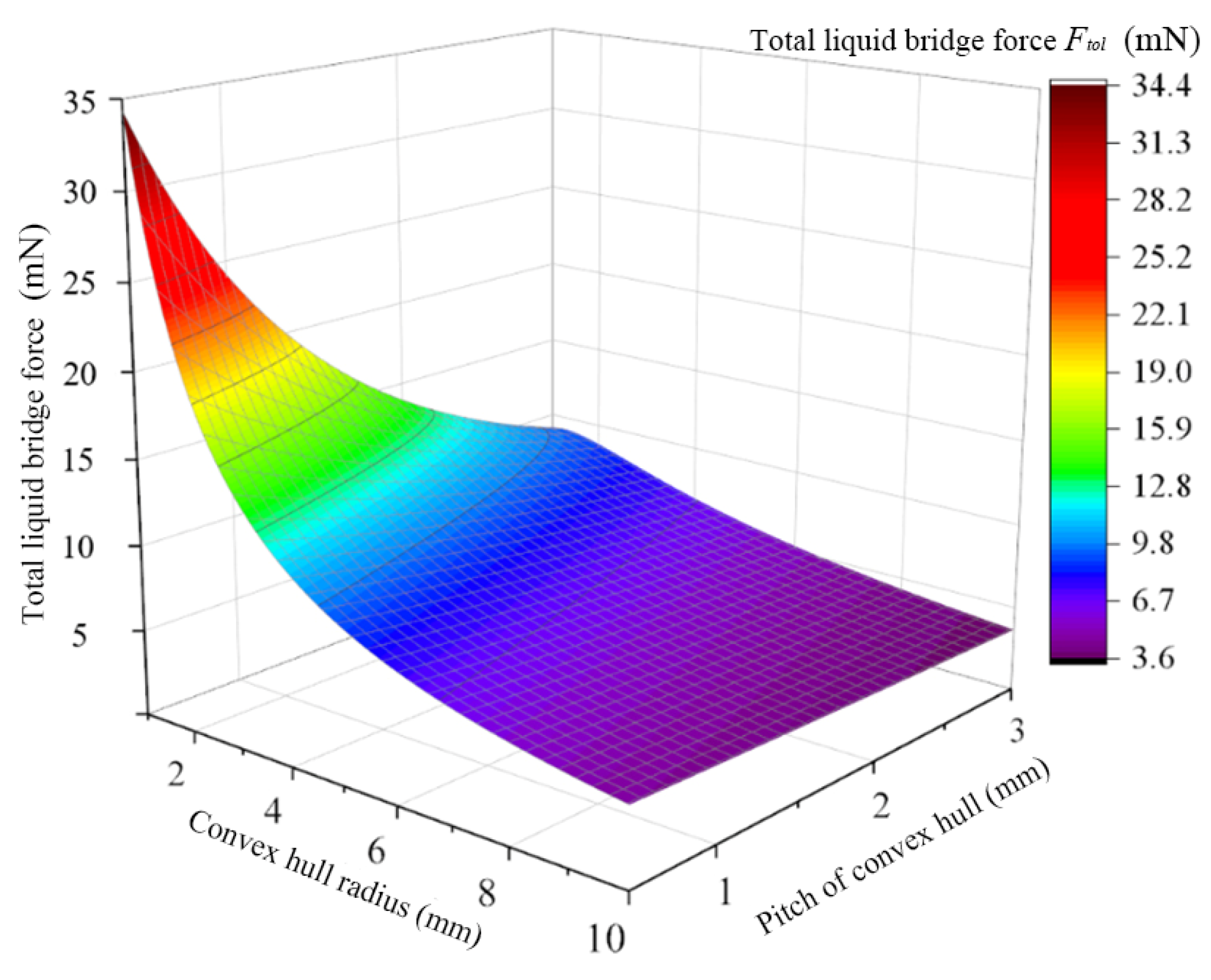
2.3.2. Establishment of a Functional Model of the Relationship Between the Total Liquid Bridge Force and the Radius and Spacing of Convex Hull

The liquid bridge volume between a single convex hull and the leaf will affect the magnitude of the liquid bridge force, and the liquid bridge volume is related to the liquid content attached to the leaf. Due to the different area of the broken leaf, the volume of liquid attached to the leaf is also different. Therefore, the liquid volume δL on the leaf per unit area is used to measure the liquid volume attached to the leaf. The value of this value is related to the surface water content of the rice plant, and the value δL can be considered to be known when the surface water content is determined. The relationship between Leaf surface area and volume and mass is also affected by shape, so leaf mass per unit area, or Leaf mass per area (LMA), is used to relate surface area to mass. According to Table 1, the LMA value of the leaf is approximately 50 g·m−2.
The water in the rice leaves will evaporate quickly under the influence of the fan. In this study, a low-temperature high-speed air flow with a temperature of 20 °C and a wind speed of 20 m·s−1 was used to simulate the rapid evaporation of water on the surface of the leaf. The weight of the leaves before and after evaporation was measured to calculate the surface water mass, and the results are shown in Table 2.
In Table 2, the changed value is the mass of the free water originally attached to the leaves. The mass of the leaves after evaporation is the original dry mass. So, the mass of free water on the surface of dry rice leaves is 23.1%. The mass δL of free water per unit area on the leaf surface is calculated to be 11.5 g·m−2. The calculation method of the total volume of liquid attached to the leaf is shown in Equation (12).
V t = δ L A l ρ l
When the leaf is in contact with the convex hull, the number of convex hull contacted by the leaf will not only affect the magnitude of a single liquid bridge force, but also affect the total adhesion force. The calculation method is shown in Equation (13).
n c = β A l
Assuming that the liquid attached to the leaf surface is evenly distributed to each convex hull in contact with the leaf, the average volume of the liquid bridge between each convex hull and the leaf is calculated according to Equation (14).
V s = V t n c = 3 2 r s + d s 2 δ L 2 3 ρ l
Combined with Equation (8), the liquid bridge force between the leaf and the wall can be obtained as shown in Equation (15).
F t o l = n c F l g = β A l π R γ e A h 2 R + B + C
By substituting the variables in Equation (15), the functional relationship between the total liquid bridge force Ftol and the convex hull structure parameters can be obtained, as shown in Equation (16).
F t o l = 2 3 A l π R γ 3 2 r s + d s 2 e 1.9 V R 3 0.51 h 2 R + 0.016 ln V 0.76 θ 2 0.012 ln V R 3 + 1.2 + 0.013 ln V R 3 + 0.18                                                      
In order to make the contact between the extruded object and the bionic convex hull wall more reasonable, the structural parameters of the convex hull are set to the order of magnitude similar to the shape and size of the extruded object. Since the shape parameters of rice extrusions are concentrated between 1 mm and 10 mm, the radius of convex hull is set to be between 1 mm and 10 mm. In order to avoid direct contact between the extruded object and the convex hull wall, the convex hull spacing should not be too large. At the same time, the spacing is too small or tends to zero, which will cause the liquid bridge between each convex hull and the leaf to affect each other, and will increase the difficulty and cost of processing. Therefore, the value range of convex hull spacing is set from 0.5 mm to 3 mm. Based on the value range of the above convex hull structure parameters, a three-dimensional surface diagram of the total liquid bridge force Ftol, the radius rs of the convex hull and the pitch ds of the convex hull was drawn in MATLAB, as shown in Figure 16.

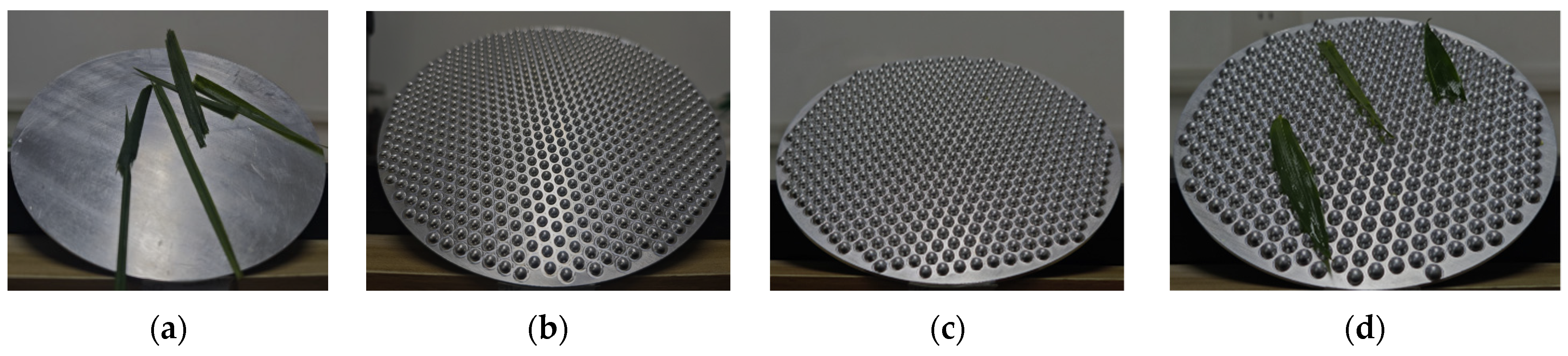
2.4. Experiment Specific Methods and Processes

2.4.1. Preparation of Wet Rice Leaves

The object of this study is the leaves of wet rice. In rainy or dewy weather, droplets gather on the surface of the rice and there is free water on the surface of the rice plant. The rice plants in this state are called wet rice, and the products obtained by threshing device are wet extrudates.
The preparation process of wet rice plants involved in this study was as follows: approximately 20 min after rain, a five-point sampling method was used to divide the sampling range, and rice plants were harvested artificially with a standard stubble height of 20 cm.
The measurement method of surface water content of wet rice is as follows: the surface water is quickly evaporated by high-speed air flow at room temperature, and the mass of the plant reduced before and after evaporation can be considered as the mass of surface water when the change in water content inside the plant can be ignored. The surface water content of wet rice leaves measured by this method is approximately 22.9%.

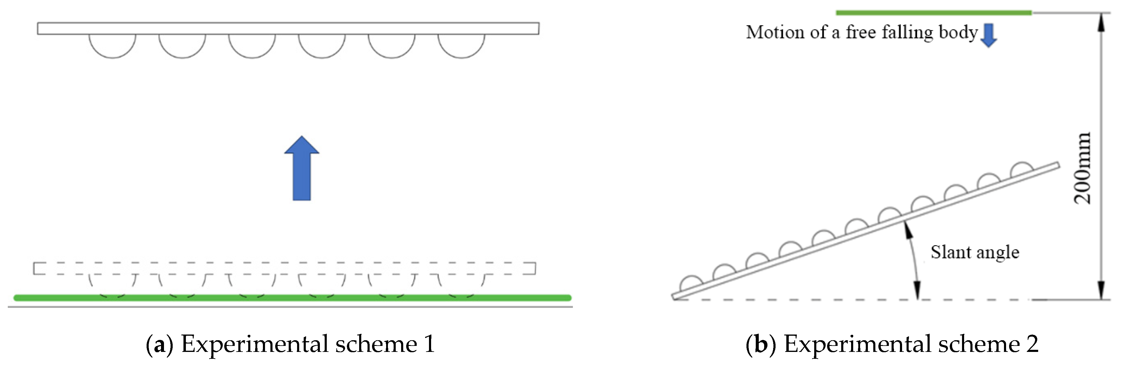
2.4.2. Design of Controlled Experiments

To study the effect of the convex hull surface structure on balancing the atmospheric pressure on both sides of the leaf and eliminating additional pressure, two sets of experiments were designed as shown in Figure 17, namely, the contact experiment of experiment 1 and the collision experiment of experiment 2. These experiments were all conducted under normal temperature and pressure. The temperature was approximately 20–25 °C, and the relative humidity was approximately 70–80%.
The scheme of experiment 1 is shown in Figure 17a. The specific process is: lay wet rice leaves on the table surface, and cover the flat leaves with at least three layers, so that the surface leaves do not directly contact the table surface. The plane surface and convex hull surface were inverted, respectively, and placed on the top of the leaf, so that the plane and convex hull surface were in full contact with the leaf. 5 s later, the plane and convex hull surface were picked up horizontally and turned over, and the leaf mass attached to the wall was counted. Each group of tests was repeated three times and the average value was taken as the final result.
As shown in Figure 17b, experiment 2 simulates the collision adhesion behavior between the screen surface and the leaf. The specific process is to place the plane and convex hull surfaces at angles of 20° and 45° with the horizontal surface. The prepared wet leaf was released freely from a height of 200 mm, so that the leaf could move in free fall and collide with the wall. The total mass of the leaf attached to the wall was counted each time. Each group of tests was repeated three times and the average value was taken as the final result.

3. Discussion

3.1. Experimental Result

In verification experiment 1, the results of five different structures of convex hull surfaces in three repeated tests are the same, and the leaf mass attached to the surface is zero. At the same time, the absence of attached leaf is not due to the leaf falling from the wall in the process of lifting the wall, but there is no attached leaf on the convex hull wall at the beginning of lifting. However, leaves of different qualities are attached in the five times of contact between the flat wall and the leaf. And the number of attached leaves is approximately 8 to 13. The specific experimental results are shown in Table 3.
From the test results, it can be concluded that the convex hull surface structure can effectively reduce the static adhesion between the leaf and the wall. And one set of test results is shown in Figure 18.
In verification experiment 2, when the inclination angle is 20° and 45°, the leaves mass of plane attached is higher than that of convex hull surface, and when the inclination angle is 45°, the mass of attached leaves is lower than that when the inclination angle is 20°, and there will be almost no attached leaves on the convex hull surface.
When the inclination angle of the inclined plane is 20°, the leaf can form a relatively stable liquid bridge with the plane and adhere to the wall. When the lower layer accumulation is formed, the subsequent leaf will continue to accumulate. However, on the convex hull surface, the leaf accumulation is also unstable, and the leaf breakage degree attached to the wall is relatively high, and most of the leaves are embedded in the gap between the convex hull. This contact will not be stable, and subsequent leaf collisions will break this relationship. One set of test results is shown in Figure 19. And the specific experimental results are shown in Table 4.
When the inclination angle of the bevel is 45°, for the plane, there will always be adhesion when the leaf continuously collides with the wall. The shape of the leaf attached to the flat wall is relatively flat, and there is a stable liquid bridge between the leaf and the wall. However, on the convex hull surface, there are few leaves attached, and the attached leaves are easy to be knocked off by subsequent leaves. One set of test results is shown in Figure 20. And the specific experimental results are shown in Table 4.
It can be seen from the above two experiment results that changing the inner wall of the cleaning device to a convex hull structure can effectively reduce the adhesion between the leaf and the wall.

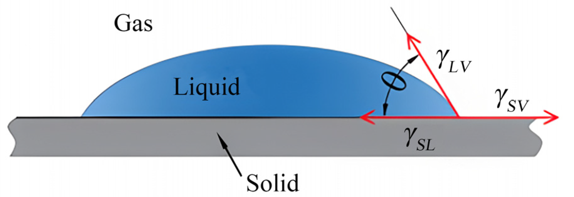
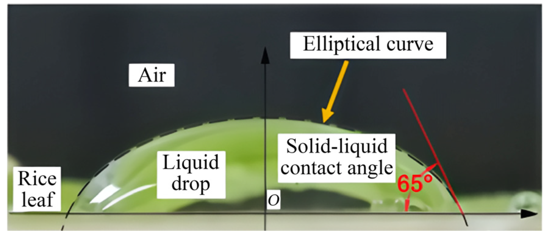
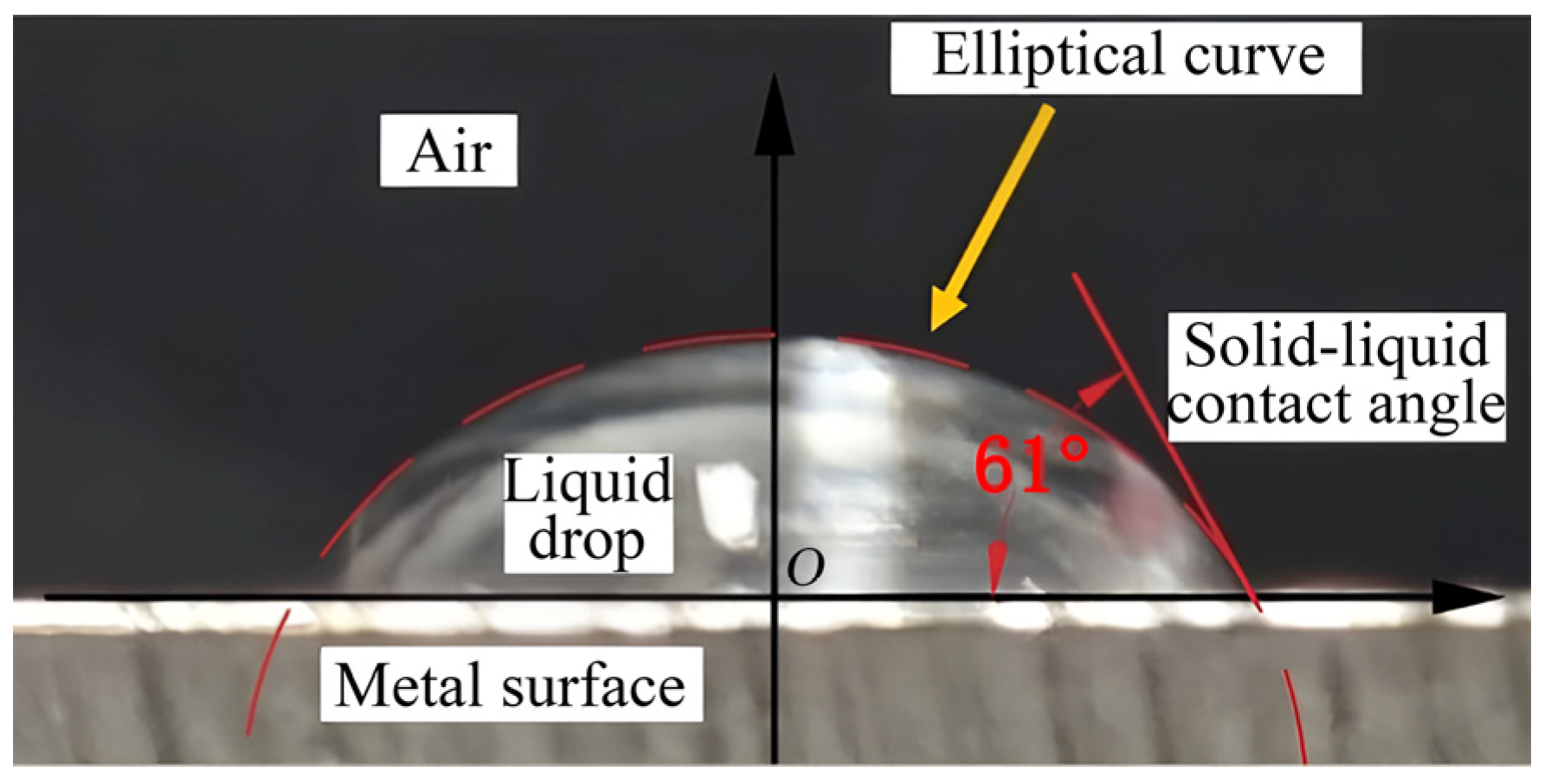
3.2. Surface Wetting Ability Analysis of Rice Leaves and Metal Plane

The wet rice extract contains seeds, broken rice leaves and stalks, which have different shapes and sizes, and different contact modes and contact areas with the metal wall of the cleaning device. As shown in Figure 21, the content of leaves in extrusions is not high, but the shape of rice leaves is flat and slender, and its contact area with the metal surface is often the largest, and the adhesion problem is also the most serious.
According to the relation theory between the free energy of the material surface and the contact angle proposed by Young, the contact angle θ formed between the three phases of gas, liquid and solid can be calculated by Equation (17) when the droplet reaches the equilibrium state on the solid surface, as shown in Figure 22. A contact angle of 90° is the boundary between hydrophilic surface and hydrophobic surface, and a contact angle greater than 90° indicates that the surface is easy to be wetted—otherwise, it is not easy to be wetted.
cos θ = γ S V γ S L γ L V
The curves of the liquid surfaces were extracted from the rice leaves and the metal wall, and the elliptic curves were synthesized by the least square method. The tangent slope and contact angle of the elliptic curve at the gas–solid–liquid junction were calculated. As shown in Figure 23 and Figure 24, after multiple measurements and averaging, the contact angle of rice leaves is 65°, and that of the metal wall is 61°, both of which are less than 90°, indicating that both rice leaf and metal wall are hydrophilic surfaces. Therefore, liquid bridge is easily formed between rice leaves and metal surface under the action of liquid. Liquid bridge force makes the two adsorbed each other and difficult to separate.

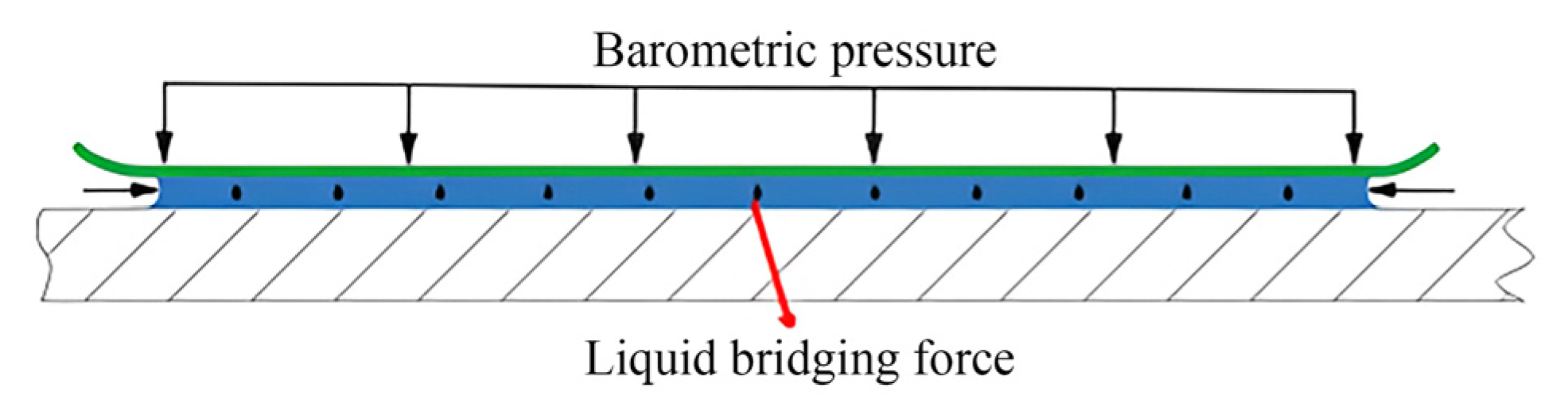
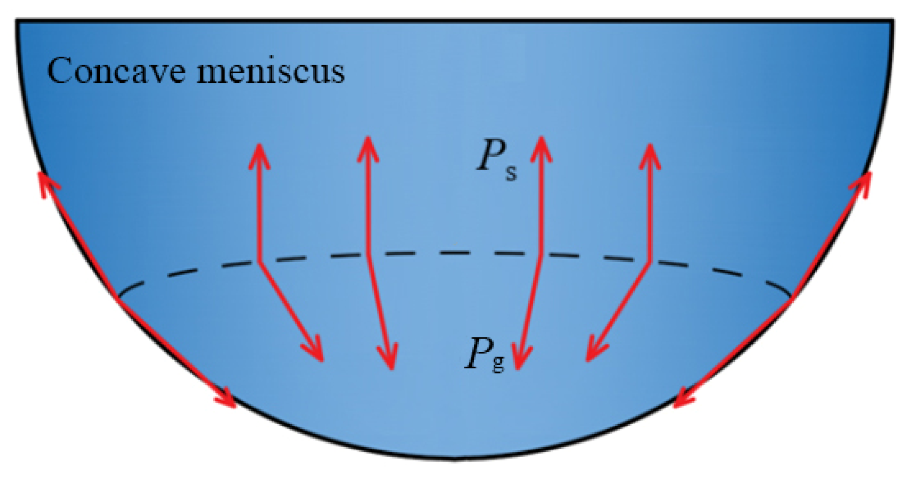
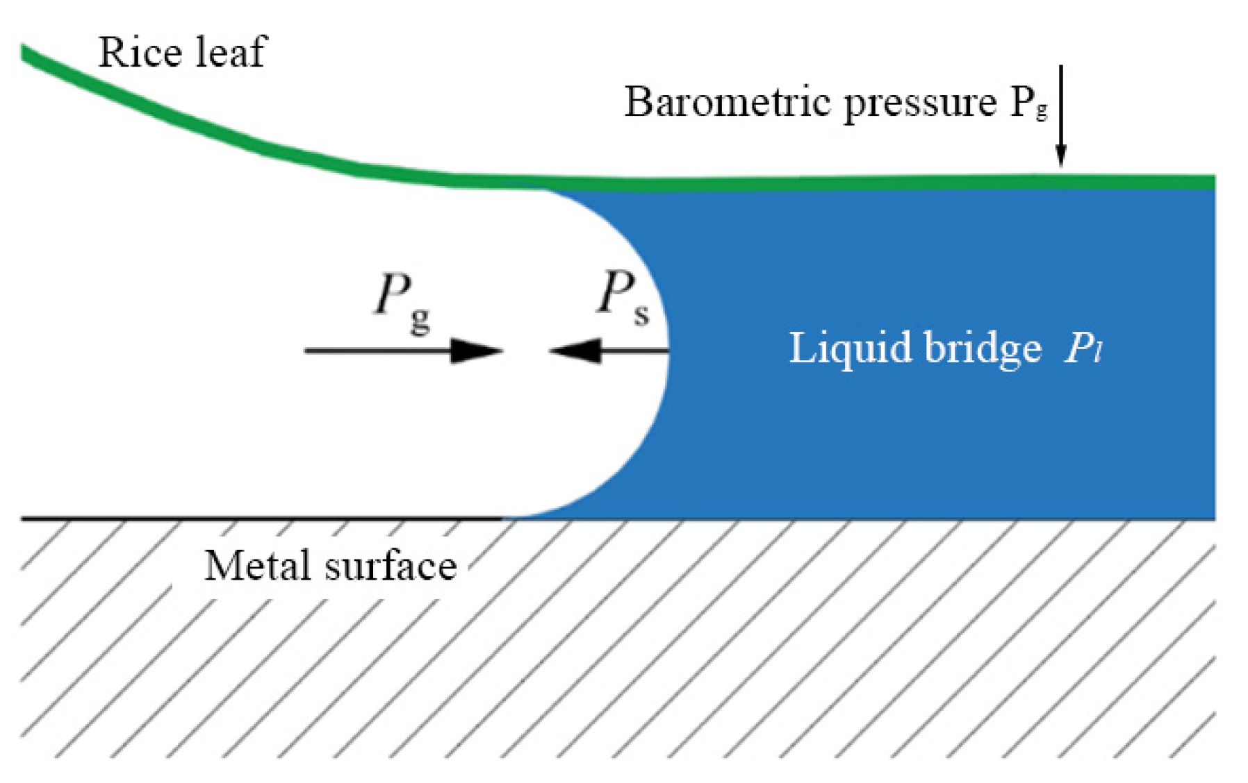
3.3. Mechanical Analysis Between Wet Rice Leaf and Metal Wall

The formation of liquid bridge force not only belongs to the category of solid–liquid contact, but also is related to the action of atmospheric pressure. For an object fully exposed to the atmosphere, the resultant force of the atmospheric pressure on the surface of the object is generally regarded as 0. As shown in Figure 25, the wet rice leaf is adhered to the metal surface, and one part of the surface is in contact with the liquid bridge, and the other part is in contact with the air. There is a difference between the pressure inside the liquid bridge and the atmospheric pressure, and the resultant force on the leaf is not 0. Further analysis and calculation of the pressure inside the liquid bridge are needed to determine the direction of the resultant force on the leaf.
As shown in Figure 26, due to surface tension, the molecules at the surface interface experience an unbalanced force and produce a resultant force directed inside the raised phase surface. This extra pressure caused by the bending of the liquid level is called the additional pressure Ps. The total pressure inside the concave surface is Pg-Ps, so it is less than the pressure on the flat surface.
As shown in Figure 27, the liquid bridge boundary formed by the liquid between the rice leaf and the metal wall is a concave liquid surface, that is, the atmospheric pressure is higher than the pressure on the liquid bridge surface. For a liquid bridge at rest, the internal pressure Pl can be considered equal everywhere, and the pressure magnitude can be calculated by Equation (18).
P l = P g P s
As shown in Figure 28, when there is a relative movement trend between the wet rice leaf and the metal wall, the vertical component force makes the leaf move away from the metal wall, thus increasing the distance between the two, resulting in more air flow between the liquid bridge and a decrease in the liquid bridge force. At this time, the liquid bridge force will hinder the separation of the leaf from the metal wall, and the direction of the force is opposite to the movement trend of the leaf. If the contact area between the broken rice leaf and the wall is 4 × 10⁻⁴ m2, the resistance Fs received by the rice leaf can be calculated as 40.52 N by Equation (19).
F s = P g P l A l
Therefore, the factors that affect the liquid bridge force are the pressure difference on both sides of the leaf and the contact area between the leaf and the metal wall. The adhesion between wet rice leaf and metal wall can be reduced by balancing the pressure on both sides of rice leaf and changing the shape of liquid bridge. If the contact area between rice leaves and metal surface is reduced, the liquid bridge formed will be less and the liquid bridge force will be weakened.

3.4. Analysis of Adhesion Reduction in the Dung Beetle Surface Convex Envelope Structure

Dung beetles exhibit excellent adhesion reduction when in contact with soil thanks to their convex surface structure. When the dirt comes into contact with the beetle’s back, the space between the bumps forms a layer of air, effectively reducing soil adhesion. Based on the surface structure and the principle of reducing adhesion of dung beetle, this structure was applied to the macroscopic visco-reducing surface design through the bionics research method, which balanced the pressure difference between the two sides of the leaf when it contacted the wall, thereby reducing the influence of additional pressure on the contact between the leaf and the wall, and reducing the adhesion between the leaf and the wall. Based on the principle of the surface structure and adhesion reduction in dung beetle, this structure was applied to the macroscopic design of surface adhesion reduction through bionics.
In the experiments, when the wet rice leaf is in contact with the convex hull on the metal plate, due to the action of the liquid surface tension, the liquid on the leaf surface will be distributed to various contact positions and gather in the area where the leaf is in contact with the spherical surface. Because there are gaps between the convex hull, when the liquid has not completely filled these gaps, an air layer will be formed between the leaf and the wall, so as to balance the air pressure on both sides of the leaf, eliminate the additional pressure generated by the liquid bridge, and reduce the adhesive force between the leaf and the wall.

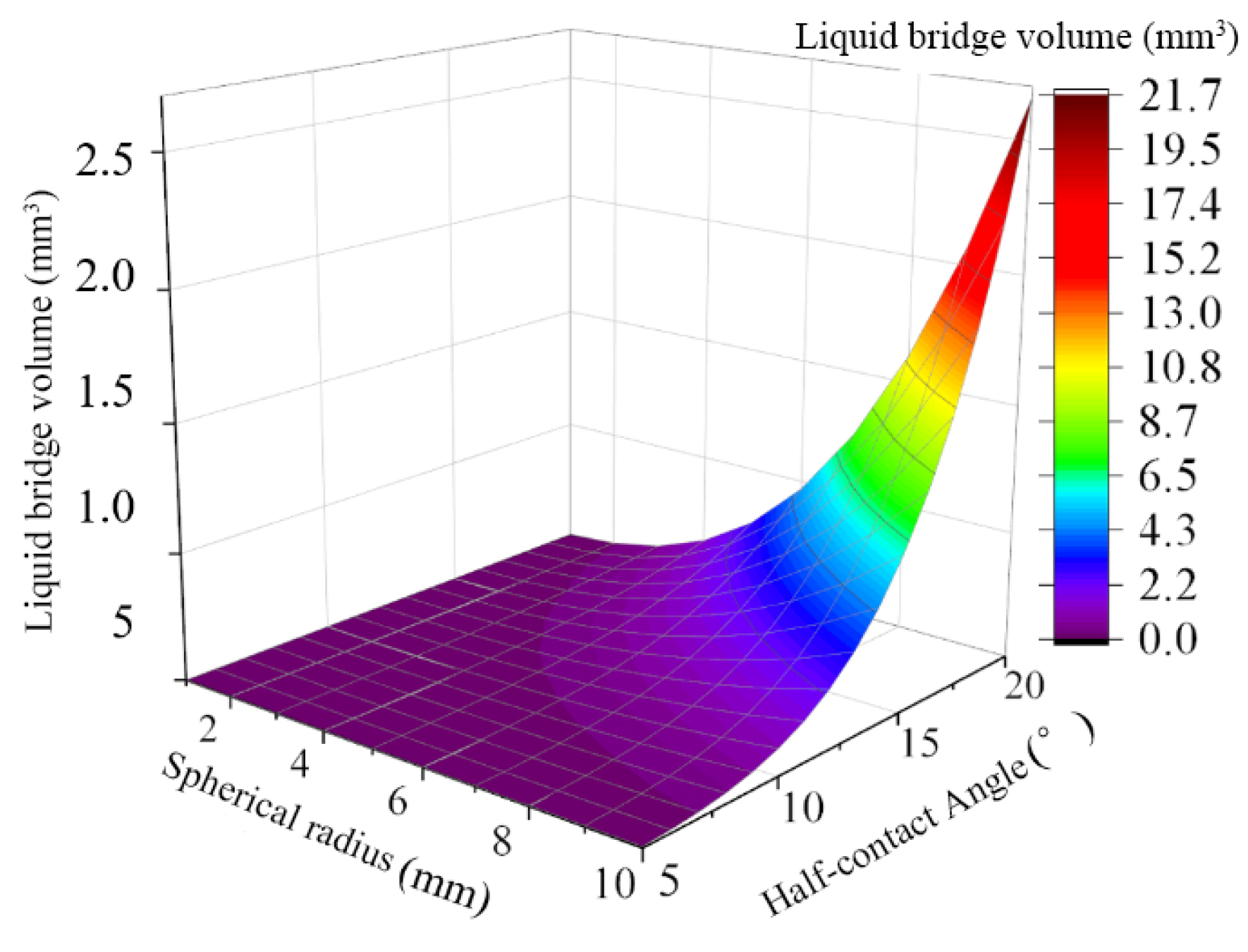
3.5. Analysis of Structural the Parameters of Bionic Convex Hull

According to Figure 16, the total liquid bridge force has no extreme value in the value range of convex hull structure parameters, and the minimum value is obtained at the edge of the value range of convex hull structure parameters. Because the partial value range of the convex hull structural parameters in the figure cannot be obtained in practice, it is necessary to further determine the range of structural parameters that meet the conditions.
Since the liquid bridge volume is related to the spherical radius, spacing and half-contact angle. When the radius of the sphere is determined, the volume of liquid bridge that can be accommodated between the sphere and the plane is limited. If the liquid volume exceeds this upper limit, the liquid will diffuse into the gap between the sphere and the plane, losing the shape characteristics of the liquid bridge [55,56].
In order to prevent the liquid from filling the gap between the convex hull, the radius and gap of the convex hull must be ensured to be large enough. The distance and radius of the convex hull also affect the number of convex hull on the wall surface per unit area, thus changing the number of convex hull contacted by the leaf per unit area. This also causes a change in the volume of the liquid bridge dispersed between the leaf and the contact position, which in turn affects the liquid bridge force at each contact position and the overall viscous force between the leaf and the wall.
Therefore, the surface structure parameters of convex hull need to ensure that the liquid volume between a single convex hull sphere and the wall is not greater than the maximum volume of liquid bridge that can be accommodated under the convex hull parameter. As can be seen from Equations (7) and (14), the inequality shown in Equation (20) must be satisfied to meet the above conditions.
By solving the above inequalities, the range of convex hull structure parameters satisfying the liquid bridge volume relation is obtained. In the process of solving, the distance h between the sphere and the plane is taken as 1/100 of the radius of the convex hull, and the half-contact angle is set as 20°. The expressions on both sides of the inequality in Equation (20) were modeled, respectively, and the three-dimensional surface diagram of volume variation with convex hull radius and convex hull spacing was drawn in MATLAB, as shown in Figure 29.
3 2 r s + d s 2 δ L 2 3 ρ l < π a 2 + ρ 1 2 ρ 1 c o s φ + θ + c o s θ                               1 3 ρ 1 3 c o s 3 φ + θ + c o s 3 θ                                             a ρ 1 2 s i n φ + θ c o s φ + θ + s i n θ c o s θ + a ρ 1 2 φ + 2 θ π                                                                                     1 3 2 - 3 c o s φ + c o s 3 φ R 3                                                            
In Figure 29, the yellow surface represents the maximum liquid bridge volume that can be accommodated between the convex hull and the leaf, and the blue surface represents the actual liquid bridge volume. The influence of convex hull spacing on the actual liquid bridge volume is small, and when the convex hull radius is small, the actual liquid bridge volume exceeds the maximum liquid bridge volume. Therefore, the convex hull parameter corresponding to the actual liquid bridge volume larger than the maximum liquid bridge volume in the figure should be removed.
In addition, when the number of convex hull per unit area of the wall is small, the surface of the leaf contact convex hull may be deformed, thus changing its contact state with the wall. As the hull density decreases further, the leaf may even touch the plane at the bottom of the hull. Therefore, the convex hull density on the wall should not be too low. It should be ensured that the number of convex hull per unit area in Equation (13) is not less than 3, and the convex hull parameters that do not meet this condition should be ignored. Finally, the relationship between the total liquid bridge force and the convex hull parameters as shown in Figure 30 can be obtained. The results in the figure show that when the radius of the convex hull is 2.47 mm and the distance between the convex hull is 1.38 mm, the total liquid bridge force is the smallest.
The research on the structural design for reducing surface adhesion is only beginning. Due to the fact that the liquid bridge force varies with different contact states, the process of wet rice threshing and cleaning becomes more complicated. In the future, optimization algorithms will be considered to optimize the convex hull structure to obtain the optimal design and more universal rules [57,58] and apply the convex hull structure to the cleaning device to validate effectiveness in practical applications.

4. Conclusions

In this paper, the feasibility of adhesion reduction between wet rice leaves and the wall of the cleaning device was studied. And the idea of applying the microscopic hydrophobic structures on the back of dung beetles to the macroscopic level was proposed.
(1)
The results show that the adhesion between the wet leaf and the wall is the largest when the additional pressure is present. When there is a gap between the convex hulls, that is, when there is an air layer between the wet leaves and the wall surface of the cleaning device, the adhesion effect would be reduced.
(2)
From the contact experiment results, it can be concluded that the convex hull surface structure can effectively reduce the static adhesion between the leaf and the wall. And the impact experiment results show that, compared with the plane surface, the adsorption capacity of the wet leaf on the convex hull surface is less, the shedding rate is higher, and the adhesion reduction effect is better.
(3)
A metal wall with a convex hull structure is proposed by the bionics method. The simulation results show that the minimum liquid bridge force exists when the convex hull radius and the convex hull spacing are 2.47 mm and 1.38 mm, respectively. The contact experiment results show that the static adhesion between the convex hull surface and the wet leaf is worse than that of the plane surface, and the adhesion reduction effect is better.

Author Contributions

Conceptualization Z.T.; methodology, Z.T. and Q.H.; validation, T.G.; formal analysis, Q.H. and T.G.; data curation, Q.H. and T.G.; investigation, T.G. and P.Q.; writing—original draft preparation, Q.H. and T.G.; writing—review and editing, P.Q. supervision, P.Q. All authors have read and agreed to the published version of the manuscript.

Funding

This research work was supported by the Natural Science Foundation of Jiangsu Province (BK20221368), the Key Laboratory Equipment of Modern Agricultural Equipment and Technology (Jiangsu University), Ministry of Education (MAET202326), the Nantong Social Livelihood Science and Technology Project (MS2023016), the Innovation and Practice Fund Project of the School of Artificial Intelligence and Intelligent Manufacturing of Jiangsu University (Grant No. RZCX2024053), and the Postgraduate Research & Practice Innovation Program of Jiangsu Province (SJCX24_2406).

Institutional Review Board Statement

Not applicable.

Data Availability Statement

The data used to support the findings of this study are available from the corresponding author upon request.

Conflicts of Interest

The authors declare no conflict of interest.

Nomenclature

βNumber of convex hull per unit area
rsRadius of convex hull (m)
dsPitch of convex hull (m)
∆pLiquid bridge gas–liquid pressure difference (Pa)
γLiquid surface energy coefficient (0.0728 J at 20 °C)
ρ1Radius of liquid surface arc (m)
ρ2Distance from liquid level to center of rotation (m)
RSpherical radius (m)
φHalf-contact angle (°)
hThe distance from the sphere to the plane (m)
θContact angle (°)
aThe length of line segment O2G (m)
VLiquid bridge volume (m3)
FlgStatic liquid bridge force (N)
VtVolume of liquid attached to leaf surface (m3)
δLLiquid mass per unit area of the leaf (kg)
AlThe area of one side surface of the leaf (m2)
ρlThe density of liquid (kg/m3)
ncNumber of convex hull in leaf contact
FtolLiquid bridge force between leaf and wall (N)
γSVSolid–gas surface free energy (J)
γSLSolid–liquid surface free energy (J)
γLVLiquid–gas surface free energy (J)
PlThe average pressure inside the liquid bridge (Pa)
PgStandard atmospheric pressure (Pa)
PsAdditional pressure (Pa)
FsLiquid bridge resistance (N)
AlContact area between rice leaf and wall (m2)
VsThe average volume of the liquid bridge between the individual convex hull and the leaf (m3)

References

  1. Zhang, T.; Li, Y.M.; Xu, L.Z.; Liu, Y.B.; Ji, K.Z.; Jiang, S. Experimental Study on Fluidization Behaviors of Wet Rice Threshed Materials with Hot Airflow. Agriculture 2022, 12, 601. [Google Scholar] [CrossRef]
  2. Zhong, Y.; Sun, J.; Yao, K.; Cheng, J.; Du, X. Detection of rice (with husk) moisture content based on hyperspectral imaging technology combined with MSLPP–ESMA–SVR model. J. Food Saf. 2024, 44, e13112. [Google Scholar] [CrossRef]
  3. Liang, Z.; Li, Y.; De Baerdemaeker, J.; Xu, L.; Saeys, W. Development and testing of a multi-duct cleaning device for tangential-longitudinal flow rice combine harvesters. Biosyst. Eng. 2019, 182, 95–106. [Google Scholar] [CrossRef]
  4. Xu, L.; Chai, X.; Gao, Z.; Li, Y.; Wang, Y. Experimental study on driver seat vibration characteristics of crawler-type combine harvester. Int. J. Agric. Biol. Eng. 2019, 12, 90–97. [Google Scholar] [CrossRef]
  5. Ding, B.C.; Liang, Z.W.; Qi, Y.Q.; Ye, Z.K.; Zhou, J.H. Improving Cleaning Performance of Rice Combine Harvesters by DEM-CFD Coupling Technology. Agriculture 2022, 12, 1457. [Google Scholar] [CrossRef]
  6. Iqbal, B.; Alabbosh, K.F.; Jalal, A.; Suboktagin, S.; Elboughdiri, N. Sustainable food systems transformation in the face of climate change: Strategies, challenges, and policy implications. Food Sci. Biotechnol. 2024, 34, 871–883. [Google Scholar] [CrossRef]
  7. Ji, K.; Li, Y.; Liu, Y.; Yu, Z.; Cheng, J. Vibration signal extraction and analysis of combine harvester based on low-pass filter-eemd combination. Eng. Agrícola 2025, 44, e20240006. [Google Scholar] [CrossRef]
  8. Li, Y.; Xu, L.; Lv, L.; Shi, Y.; Yu, X. Study on Modeling Method of a Multi-Parameter Control System for Threshing and Cleaning Devices in the Grain Combine Harvester. Agriculture 2022, 12, 1483. [Google Scholar] [CrossRef]
  9. Zhang, T.; Li, Y.; You, G. Experimental Study on the Cleaning Performance of Hot Air Flow Cleaning Device. Agriculture 2023, 13, 1828. [Google Scholar] [CrossRef]
  10. Wang, L.; Chai, X.; Huang, J.; Hu, J.; Cui, Z. Efficient and Low-Loss Cleaning Method for Non-Uniform Distribution of Threshed Materials Based on Multi-Wing Curved Combination Air Screen in Computational Fluid Dynamics/Discrete Element Method Simulations. Agriculture 2024, 14, 895. [Google Scholar] [CrossRef]
  11. Liu, W.; Zeng, S.; Chen, X. Vortex Cleaning Device for Rice Harvester: Design and Bench Test. Agriculture 2024, 14, 866. [Google Scholar] [CrossRef]
  12. Cai, J.; Ma, J.; Zhang, Z.; Chen, X.; Liu, D.; Liang, C. Fragmentation of wet agglomerates after normal impact with a flat surface: Experimental study and DEM simulation. Chem. Eng. Sci. 2025, 307, 121339. [Google Scholar] [CrossRef]
  13. Liu, Y.; Li, Y.; Chen, L.; Zhang, T.; Liang, Z.; Huang, M.; Su, Z. Study on Performance of Concentric Threshing Device with Multi-Threshing Gaps for Rice Combines. Agriculture 2021, 11, 1000. [Google Scholar] [CrossRef]
  14. Hussain, S.; Jianjun, H.; Yong, C.; Ali, A.; Song, H.; Zheng, D.; Farid, M.U.; Ghafoor, A.; Ahmed, M. CFD study of self-cleaning system of multi-stage tangential roller threshing unit for precise buckwheat breeding. Heliyon 2024, 10, e27180. [Google Scholar] [CrossRef]
  15. Fu, J.; Zhang, M.; Cheng, C.; Zhao, H.; Ren, L. Mechanism study of the effect of a surface liquid film on the collision adhesion behaviour of rice stalks. Biosyst. Eng. 2025, 251, 61–72. [Google Scholar] [CrossRef]
  16. Cheng, C.; Fu, J.; Chen, Z.; Ren, L. Effect of vibration parameters of vibrating screen for harvester on adhesion characteristics of threshed mixtures with different moistures. Trans. Chin. Soc. Agric. Eng. Trans. CSAE 2019, 35, 29–36. [Google Scholar] [CrossRef]
  17. De Bisschop, F.R.E.; Rigole, W.J.L. A physical model for liquid capillary bridges between adsorptive solid spheres: The nodoid of plateau. J. Colloid Interface Sci. 1982, 88, 117–128. [Google Scholar] [CrossRef]
  18. Lian, G.; Thornton, C.; Adams, M.J. A Theoretical Study of the Liquid Bridge Forces between Two Rigid Spherical Bodies. J. Colloid Interface Sci. 1993, 161, 138–147. [Google Scholar] [CrossRef]
  19. Pitois, O.; Moucheront, P.; Chateau, X. Liquid Bridge between Two Moving Spheres: An Experimental Study of Viscosity Effects. J. Colloid Interface Sci. 2000, 231, 26–31. [Google Scholar] [CrossRef]
  20. Pitois, O.; Moucheront, P.; Chateau, X. Rupture energy of a pendular liquid bridge. Eur. Phys. J. B-Condens. Matter Complex Syst. 2001, 23, 79–86. [Google Scholar] [CrossRef]
  21. Darabi, P.; Li, T.; Pougatch, K.; Salcudean, M.; Grecov, D. Modeling the evolution and rupture of stretching pendular liquid bridges. Chem. Eng. Sci. 2010, 65, 4472–4483. [Google Scholar] [CrossRef]
  22. Soulié, F.; Cherblanc, F.; El Youssoufi, M.S.; Saix, C. Influence of liquid bridges on the mechanical behaviour of polydisperse granular materials. Int. J. Numer. Anal. Methods Geomech. 2006, 30, 213–228. [Google Scholar] [CrossRef]
  23. Rossetti, D.; Pepin, X.; Simons, S.J.R. Rupture energy and wetting behavior of pendular liquid bridges in relation to the spherical agglomeration process. J. Colloid Interface Sci. 2003, 261, 161–169. [Google Scholar] [CrossRef] [PubMed]
  24. Lu, N.; Lechman, J.; Miller, K.T. Experimental Verification of Capillary Force and Water Retention between Uneven-Sized Spheres. J. Eng. Mech. 2008, 134, 385–395. [Google Scholar] [CrossRef]
  25. Lievano, D.; Velankar, S.; McCarthy, J.J. The rupture force of liquid bridges in two and three particle systems. Powder Technol. 2017, 313, 18–26. [Google Scholar] [CrossRef]
  26. Wang, J.-P.; Gallo, E.; François, B.; Gabrieli, F.; Lambert, P. Capillary force and rupture of funicular liquid bridges between three spherical bodies. Powder Technol. 2017, 305, 89–98. [Google Scholar] [CrossRef]
  27. Pu, C.; Liu, F.; Zhang, Z.; Cheng, J.; Zhao, W. Experimental study on liquid force and profile between two moving sphere particles under different liquid content condition. J. Hydraul. Eng. 2020, 51, 81–91. [Google Scholar]
  28. Liu, J.-L.; Li, G.-S.; Nie, Z.-X. Morphology and Liquid Bridge Force of an Axisymmetric Liquid Bridge. J. Xihua Univ. Nat. Sci. Ed. 2010, 29, 1–5. [Google Scholar]
  29. Wang, X.W.; Yu, Y. Study of Gravitation Effect on Rupture Distance of Liquid Bridge between Two Flat Substrates. J. Exp. Mech. 2012, 27, 70–76. [Google Scholar]
  30. He, Y.; Wu, J.; Xiao, S.; Fang, H.; Zheng, Q. Investigating the Wettability of Rapeseed Leaves. Appl. Eng. Agric. 2021, 37, 399–409. [Google Scholar] [CrossRef]
  31. Pang, D.; Cong, H.; Li, X.; Li, H.; Gao, X. Liquid-bridge Flow between Two Slender Plates: Formation and Fluid Mechanics. Chem. Eng. Res. Des. 2021, 170, 304–313. [Google Scholar] [CrossRef]
  32. Yang, L.; Chen, Z.Y.; Xiao, H.P. Calculation of volume at both ends of liquid bridge between two parallel plates. Coll. Phys. 2021, 40, 12–14. [Google Scholar] [CrossRef]
  33. Wang, X.; Zhou, H.; Tong, J. The simplification and analytical verification of the static liquid bridge force model for particle adhesion in inferior seedling substrates. Surf. Interfaces 2024, 53, 104994. [Google Scholar] [CrossRef]
  34. Ma, J.; Liu, K.; Dong, X.; Chen, C.; Qiu, B.; Zhang, S. Effects of Leaf Surface Roughness and Contact Angle on In Vivo Measurement of Droplet Retention. Agronomy 2022, 12, 2228. [Google Scholar] [CrossRef]
  35. Zhao, J.; Yu, G.; Jiang, G. Fabrication of a Bionic Superhydrophobic Surface with Photothermal and Electrothermal Performance for All-Weather Anti-Icing. Langmuir ACS J. Surf. Colloids 2025, 41, 7580–7591. [Google Scholar] [CrossRef]
  36. Neinhuis, C.; Barthlott, W. Characterization and Distribution of Water-repellent, Self-cleaning Plant Surfaces. Ann. Bot. 1997, 79, 667–677. [Google Scholar] [CrossRef]
  37. Lin, N.; Liu, X.Y. Correlation between hierarchical structure of crystal networks and macroscopic performance of mesoscopic soft materials and engineering principles. Chem. Soc. Rev. 2015, 44, 7881–7915. [Google Scholar] [CrossRef]
  38. Yang, J.; Liu, G.; Zhang, K.; Li, P.; Yan, H.; Yan, Y.; Zheng, Y.; Zhao, Z.; Zhang, L.; Liu, X.; et al. Sunflower-Inspired Superhydrophobic Surface with Composite Structured Microcone Array for Anisotropy Liquid/Ice Manipulation (Small 52/2024). Small 2024, 20, 2470390. [Google Scholar] [CrossRef]
  39. Li, J.; Deng, J.; Zhou, C.; Yang, J.; Shin, S.; Binks, B.P.; Cho, N.J. Biomimetic Superhydrophobic Surfaces by Nanoarchitectonics with Natural Sunflower Pollen (Small 7/2025). Small 2025, 21, 2570048. [Google Scholar] [CrossRef]
  40. Jing, Z.; Ding, J.; Zhang, T.; Yang, D.; Qiu, F.; Chen, Q.; Xu, J. Flexible, versatility and superhydrophobic biomass carbon aerogels derived from corn bracts for efficient oil/water separation. Food Bioprod. Process. 2019, 115, 134–142. [Google Scholar] [CrossRef]
  41. Zhang, J.; Huang, X.; Shi, J.; Liu, L.; Zhang, X.; Zou, X.; Xiao, J.; Zhai, X.; Zhang, D.; Li, Y.; et al. A visual bi-layer indicator based on roselle anthocyanins with high hydrophobic property for monitoring griskin freshness. Food Chem. 2021, 355, 129573. [Google Scholar] [CrossRef] [PubMed]
  42. Yue, P.; Zhang, M.; Zhao, T.; Liu, P.; Peng, F.; Yang, L. Eco-friendly epoxidized Eucommia ulmoides gum based composite coating with enhanced super-hydrophobicity and corrosion resistance properties. Ind. Crops Prod. 2024, 214, 118523. [Google Scholar] [CrossRef]
  43. Sharifi, N.; Pugh, M.; Moreau, C.; Dolatabadi, A. Developing hydrophobic and superhydrophobic TiO2 coatings by plasma spraying. Surf. Coat. Technol. 2016, 289, 29–36. [Google Scholar] [CrossRef]
  44. Yang, Y.; Li, X.; Zheng, X.; Chen, Z.; Zhou, Q.; Chen, Y. 3D-Printed Biomimetic Super-Hydrophobic Structure for Microdroplet Manipulation and Oil/Water Separation. Adv. Mater. 2018, 30, 1704912. [Google Scholar] [CrossRef]
  45. Guan, C.; Fu, J.; Cui, Z.; Wang, S.; Gao, Q.; Yang, Y. Evaluation of the tribological and anti-adhesive properties of different materials coated rotary tillage blades. Soil Tillage Res. 2021, 209, 104933. [Google Scholar] [CrossRef]
  46. Xie, Z.; Tian, Y.; Zhong, F.; Xiang, G.; Li, S.; Yuan, Q. Enhancing bond properties between epoxy resins and cementitious materials through entropy-driven hydrophobic interaction. Compos. Part B Eng. 2025, 296, 112251. [Google Scholar] [CrossRef]
  47. Feng, S.; Delannoy, J.; Malod, A.; Zheng, H.; Quéré, D.; Wang, Z. Tip-induced flipping of droplets on Janus pillars: From local reconfiguration to global transport. Sci. Adv. 2020, 6, eabb4540. [Google Scholar] [CrossRef]
  48. Barthlott, W.; Schimmel, T.; Wiersch, S.; Koch, K.; Brede, M.; Barczewski, M.; Walheim, S.; Weis, A.M.; Kaltenmaier, A.; Leder, A.; et al. The Salvinia Paradox: Superhydrophobic Surfaces with Hydrophilic Pins for Air Retention Under Water. Adv. Mater. 2010, 22, 2325–2328. [Google Scholar] [CrossRef]
  49. Vuckovac, M.; Latikka, M.; Liu, K.; Huhtamäki, T.; Ras, R.H.A. Uncertainties in contact angle goniometry. Soft Matter 2019, 15, 7089–7096. [Google Scholar] [CrossRef]
  50. Yuan, L.; Tang, Z.; Liu, S.; Wang, T.; Ding, Z. Design for Copying Grouser and Bionic Convex Hull Patterns on Track Surfaces of Crawler Combine Harvesters. Agriculture 2024, 14, 1079. [Google Scholar] [CrossRef]
  51. Zhan, Y.; Pang, Z.; Tan, G. Optically/thermally dual-responsive shape memory superhydrophobic surfaces with advanced multi-functionalities. Compos. Part A Appl. Sci. Manuf. 2025, 192, 108812. [Google Scholar] [CrossRef]
  52. Hotta, K.; Takeda, K.; Iinoya, K. The capillary binding force of a liquid bridge. Powder Technol. 1974, 10, 231–242. [Google Scholar] [CrossRef]
  53. Willett, C.; Adams, M.; Johnson, S.; Seville, J.P.K. Capillary Bridges between Two Spherical Bodies. Langmuir 2000, 16, 9396–9405. [Google Scholar] [CrossRef]
  54. Mikami, T.; Kamiya, H.; Horio, M. Numerical simulation of cohesive powder behavior in a fluidized bed. Chem. Eng. Sci. 1998, 53, 1927–1940. [Google Scholar] [CrossRef]
  55. Bian, X.; Huang, H.; Chen, L. Formation of special liquid bridges between a single plate and parallel plates. AIP Adv. 2019, 9, 095018. [Google Scholar] [CrossRef]
  56. He, Z.T.; Wu, C.M.; Yu, J.j.; Li, Y.R. Dynamic analysis of adsorbate behavior in nanopores: Liquid bridge formation, cavitation, and contact angle evaluation via molecular dynamics simulations. J. Mol. Liq. 2024, 414, 126146. [Google Scholar] [CrossRef]
  57. Jeyanthi, S.; Venkatakrishnaiah, R.; Raju, K.V.B. Multilayer geocell-reinforced soils using mayfly optimisation predicts circular foundation load settlement. Int. J. Hydromechatron. 2024, 7, 31–48. [Google Scholar] [CrossRef]
  58. Cunegatto, E.H.T.; Zinani, F.S.F.; Rigo, S.J. Multi-objective optimisation of micromixer design using genetic algorithms and multi-criteria decision-making algorithms. Int. J. Hydromechatron. 2024, 7, 224–249. [Google Scholar] [CrossRef]
Figure 1. Wet rice has high surface water content.
Agriculture 15 00921 g001
Figure 2. Adhesion of broken rice leaves and stalks.
Agriculture 15 00921 g002
Figure 3. Y-Liangyou rice plants.
Agriculture 15 00921 g003
Figure 4. Dung beetle and ultra-depth-of-field 3D microscope.
Agriculture 15 00921 g004
Figure 5. Surface topography feature map of dung beetle back region.
Agriculture 15 00921 g005
Figure 6. Schematic diagram of contact between the convex hull structure and rice leaf.
Agriculture 15 00921 g006
Figure 7. Quadrilateral close packing on a plane.
Agriculture 15 00921 g007
Figure 8. Hexagonal close packing on a plane.
Agriculture 15 00921 g008
Figure 9. Dung beetle surface convex hull outline.
Agriculture 15 00921 g009
Figure 10. Hexagonal close packing structure parameters.
Agriculture 15 00921 g010
Figure 11. Samples of bionic convex hull metal walls of different diameters.
Agriculture 15 00921 g011
Figure 12. Simplified model of liquid bridge between sphere and plane.
Agriculture 15 00921 g012
Figure 13. Geometric diagram of the liquid bridge between the sphere and the plane.
Agriculture 15 00921 g013
Figure 14. The relationship between liquid bridge volume and spherical radius and half-contact angle.
Agriculture 15 00921 g014
Figure 15. The relationship between liquid bridge force and spherical radius and half-contact angle.
Agriculture 15 00921 g015
Figure 16. Surface plot of the functional relationship between the total liquid bridge force Ftol and the convex hull structural parameters.
Agriculture 15 00921 g016
Figure 17. Experimental scheme diagram.
Agriculture 15 00921 g017
Figure 18. Contact experiment results photos. (a) Plane, (b) convex hull surface rs = 2 mm, (c) convex hull surface rs = 2.5 mm, and (d) convex hull surface rs = 3 mm.
Agriculture 15 00921 g018
Figure 19. The experimental results of the collision and adhesion between the wall with a tilt angle of 20° and the leaves. (a) Plane, (b) convex hull surface rs = 2 mm, (c) convex hull surface rs = 2.5 mm, and (d) convex hull surface rs = 3 mm.
Agriculture 15 00921 g019
Figure 20. The experimental results of the collision and adhesion between the wall with a tilt angle of 45° and the leaves. (a) Plane, (b) convex hull surface rs = 2 mm, (c) convex hull surface rs = 2.5 mm, and (d) convex hull surface rs = 3 mm.
Agriculture 15 00921 g020
Figure 21. Rice leaf adhered to metal surface.
Agriculture 15 00921 g021
Figure 22. Surface contact angle diagram.
Agriculture 15 00921 g022
Figure 23. Measurement of rice leaf–drop contact angle.
Agriculture 15 00921 g023
Figure 24. Combine cleaning device wall–drop contact angle measurement.
Agriculture 15 00921 g024
Figure 25. Force analysis of wet rice leaves adhering to metal surface.
Agriculture 15 00921 g025
Figure 26. Schematic diagram of additional pressure on concave surface.
Agriculture 15 00921 g026
Figure 27. Pressure analysis of different phases on rice leaf surface.
Agriculture 15 00921 g027
Figure 28. Liquid bridge force of wet rice leaves moving away from metal wall.
Agriculture 15 00921 g028
Figure 29. The relationship between the maximum volume of a liquid bridge that can be accommodated and the actual volume.
Agriculture 15 00921 g029
Figure 30. The relationship between the total liquid bridge force Ftol and the convex hull radius rs and the convex hull spacing ds.
Agriculture 15 00921 g030
Table 1. Leaf-related physical property parameters of two Y-Liangyou optimal rice plants.
VarietiesCountry of Origin/TimeLeaf Mass per Area
(g·m−2)
Leaf Thickness
(mm)
Leaf Density
(mg·mm−3)
Y-Liangyou No. 1China/200650.7 ± 0.90.33 ± 0.090.155 ± 0.003
Y-Liangyou No. 2China/201149.4 ± 0.60.33 ± 0.030.151 ± 0.002
Table 2. Test result of moisture content determination on wet leaf surface.
Group 1 (g)Group 2 (g)Group 3 (g)Group 4 (g)Group 5 (g)Average (g)
LeavesUnevaporated18.422.718.817.421.219.7
After evaporation14.918.415.214.117.416
Mass change value3.54.33.63.33.83.7
Table 3. The result of verification experiment 1.
Time1 (g)2 (g)3 (g)4 (g)5 (g)Average (g)Sample Standard Deviation
Plane1.380.981.271.081.241.190.142
Convex hull surface rs = 2 mm0000000
Convex hull surface rs = 2.5 mm0000000
Convex hull surface rs = 3 mm0000000
Table 4. The result of verification experiment 2.
Inclination AngleTime1 (g)2 (g)3 (g)4 (g)5 (g)Average (g)Sample Standard Deviation
20°Plane2.122.231.982.171.832.0660.144
Convex hull surface rs = 2 mm0.310.430.510.360.470.4160.073
Convex hull surface rs = 2.5 mm0.630.460.550.420.450.5020.077
Convex hull surface rs = 3 mm0.520.490.610.460.420.5000.064
45°Plane0.280.350.240.240.390.3000.060
Convex hull surface rs = 2 mm0000.080.050.0260.033
Convex hull surface rs = 2.5 mm000.04000.0080.016
Convex hull surface rs = 3 mm0.230.210.180.140.150.1820.034
Disclaimer/Publisher’s Note: The statements, opinions and data contained in all publications are solely those of the individual author(s) and contributor(s) and not of MDPI and/or the editor(s). MDPI and/or the editor(s) disclaim responsibility for any injury to people or property resulting from any ideas, methods, instructions or products referred to in the content.

