Article

Development and Testing of the Adaptive Control System for Profiling Grain Header

1
College of Agricultural Engineering and Food Science, Shandong University of Technology, Zibo 255200, China
2
Institute of Modern Agricultural Equipment, Shandong University of Technology, Zibo 255200, China
*
Author to whom correspondence should be addressed.
Agriculture 2025, 15(5), 473; https://doi.org/10.3390/agriculture15050473
Submission received: 19 January 2025 / Revised: 13 February 2025 / Accepted: 21 February 2025 / Published: 22 February 2025
(This article belongs to the Section Agricultural Technology)

Abstract

:
In the harvesting operation, the stubble height of the grain is a vital parameter index in the combined harvesting operation; if the stubble is too high or too low, it will directly affect the harvesting quality and the service life of the header. At present, the profiling control system can only control the lift of the header in the vertical direction but not the horizontal direction and the angle of the cutter profiling. This study proposes a contouring control strategy and system for grain harvesting by analyzing the designed contouring adjustment mechanism and simulating the control method and hydraulic system through Amesim2404 software to simulate and analyze the control method and hydraulic system. Finally, different forward speeds of the harvester (5, 7, 9, and 11 km/h) and other cutting heights of the harvester were analyzed based on static and field tests and different stubble heights (100, 150, 200, and 250 mm) on the test indexes. The results of the field test showed that for different operating speeds, the error between the mean value of stubble height and the target value was small, the absolute error was less than 2 mm, the mean value of the coefficient of variation of stubble height was 4.53%, and the mean value of control accuracy is 94%. The developed adaptive control system of the profiled grain header has high precision and stability, which can provide a reference for the all-terrain profiling control technology of the combined harvester header deck.

1. Introduction

Ensuring consistent stubble height on combine harvesters in complex operating conditions is important. Too high a stubble height can result in the header being overfed with too much straw, causing blockages that increase the load on the header, resulting in wasted energy and affecting the subsequent threshing and cleaning process [1]. In addition, stubble that is too high will also affect subsequent cultivation, resulting in unnecessary energy waste and increased labor. In the grain harvesting operation, the cutting angle of the cutter, along with the cutting platform of the shape, also changes. China has nearly 700 million mu of hilly and mountainous farmland, and its terrain has a large slope [2]. Therefore, it is difficult for the combine harvester to ensure the consistency of the stubble height during the harvesting operation, resulting in declining harvesting quality. At present, the grain combine harvester manually adjusts the vertical lift of the cutting platform for simple height profiling, which greatly increases the labor intensity of the operator. Because of the complexity of its hilly and mountainous terrain, it cannot guarantee the accuracy and stability of its harvesting. In recent years, with the automation of agricultural machinery and intelligent development, the existing grain combine harvester manually adjusting the height of a single cutter imitation has been unable to meet market demand [3]. Therefore, this paper develops an adaptive control system for grain header profiling adapted to the operation of hilly and mountainous areas in China.
A hydraulic cylinder executes the height profiling adjustment of the existing grain combine harvester header. Only the vertical lifting of the header is manually adjusted, and it is impossible to ensure the consistency of the stubble height in complex environments, resulting in missed cutting or the header touching the ground [4]. Therefore, to improve the stability and accuracy of the hydraulic control system during header height profiling, scholars have conducted extensive research on the adjustment of the harvester header. For example, Wang Q. [5] proposed an intelligent control algorithm for header profiling based on multi-sensor data fusion and model predictive control, which can accurately perform header height profiling, and also designed a hydraulic control system for header height profiling. The field test shows that the average value of the coefficient of variation is 3.5% under different operating speeds; the average control accuracy of the header is 91.5%. This control system has high precision and stability. Ni Y. [6] conducted a kinematic analysis of the interaction between the profiling mechanism and the soil. Based on this analysis, they established a mathematical model for the angular sensor and the profiling mechanism. Geng A. [7] designed a floating compression-type profiling mechanism and automatic profiling regulation technology for the domestic corn harvester cutting platform through manual control, and this study determined the torque parameter of the torsion spring of the key mechanism of the profiling mechanism as 15 N/m. Liu W. [8] for the existing harvesting machinery cannot guarantee the stubble height consistency of regenerated rice. This study designed an adaptive profiling cutting platform and based it on the PID fuzzy control method of its simulation performance test; the results show that the header platform height and leveling adjustment of the average error for the 6.75 mm is 0.64°. The team led by Wang J. [9] addressed the issue that the four JSM-type residual film recycling machine lacks a profiling function when facing complex terrains such as soft and uneven ground. They designed an electro-hydraulic automatic profiling system and, through field tests, identified the parameter combination that yields the optimal electro-hydraulic profiling effect. Jin C. [10] designed a main-auxiliary plate compression type header profiling mechanism to improve the sensitivity and accuracy of the combined harvester header profiling mechanism to changes in the field terrain. They used the particle swarm optimization algorithm to determine the level ranges of various factors. They established a mathematical regression model between the factors and indicators through the MBD-DEM co-simulation test. Zhuang X. [11] proposed a header height control strategy based on robust feedback linearization for header height control. This strategy stabilizes the system by establishing a sensitivity equation and selecting gains. It also selects a hydraulic control mechanism. According to experiments, the designed controller outperforms the traditional PID controller. Lopes T. [12] conducted research on the problem of dead zones in the existing harvester header profiling control system. By analyzing the dynamics of the combined harvester header, we derived the space–state equations of the header height. A linear quadratic Gaussian control method with loop transfer response was proposed to improve the performance of the header profiling control. However, this study only conducted simulation tests and did not conduct field profiling tests to verify the machine’s stability. Zhang T. [13] developed a control system for adaptive mimicry of stalk-and-cob fresh corn harvesting cutter, which used an ultrasonic wave distance sensor for ground information acquisition. However, complex fields with many obstacles greatly challenge the stability of ultrasonic sensors. To ensure the stubble height for grain harvesting and to reduce grain loss, Wang Z. [14] designed an adaptive mimicry control system for cutter height based on PID and fitted a mathematical relationship between the cutter height and the voltage signal. However, the traditional PID control may be difficult to provide optimal control for nonlinear systems. Li R. [15] designed a mechanical–hydraulic combined soybean header profiling mechanism to improve its profiling range for its limited range of soybean headers. We constructed the mathematical model between the hydraulic cylinder expansion and the height of the cutter from the ground. Yang R. [16] designed an adaptive height profiling control system and proposed a new EVPIVS-PID algorithm by analyzing the traditional PID algorithm and conducting simulations and field tests. The results show that based on the EVPIVS-PID algorithm, the header profiling control system has a working error of no more than 2 mm and can meet its 5–11 company harvesting speed.
Through the analysis of the above literature, it was found that most of the current research on grain combine harvester header profiling focuses on vertical height profiling and does not consider the profiling of the header in the horizontal direction; the cutting angle of the combine harvester header cutter in the harvesting operation for the quality of the harvest and harvesting power consumption has a significant impact, and the existing profiling control system research did not consider the effects of its influence [17]. It is challenging to meet the accuracy and stability of harvesting with a single-height control system for the hilly and mountainous areas with highly complex terrains. Therefore, through the analysis of the field terrain, the state of the feeder house, the state of the header, and the height of the cutter above the ground during the operation of the grain combine harvester, this paper proposes an adaptive control system for the profiling grain header to achieve accurate, stable, and real-time control of the header profiling of the grain combine harvester. The main contributions of this paper can be summarized as follows:
  • Based on the harvester’s motion laws during the harvesting operation, a profiling mathematical model for the vertical lifting motion, horizontal rotation motion of the profiling header, and the angle of the cutting knife is constructed, and an adaptive profiling control strategy is proposed.
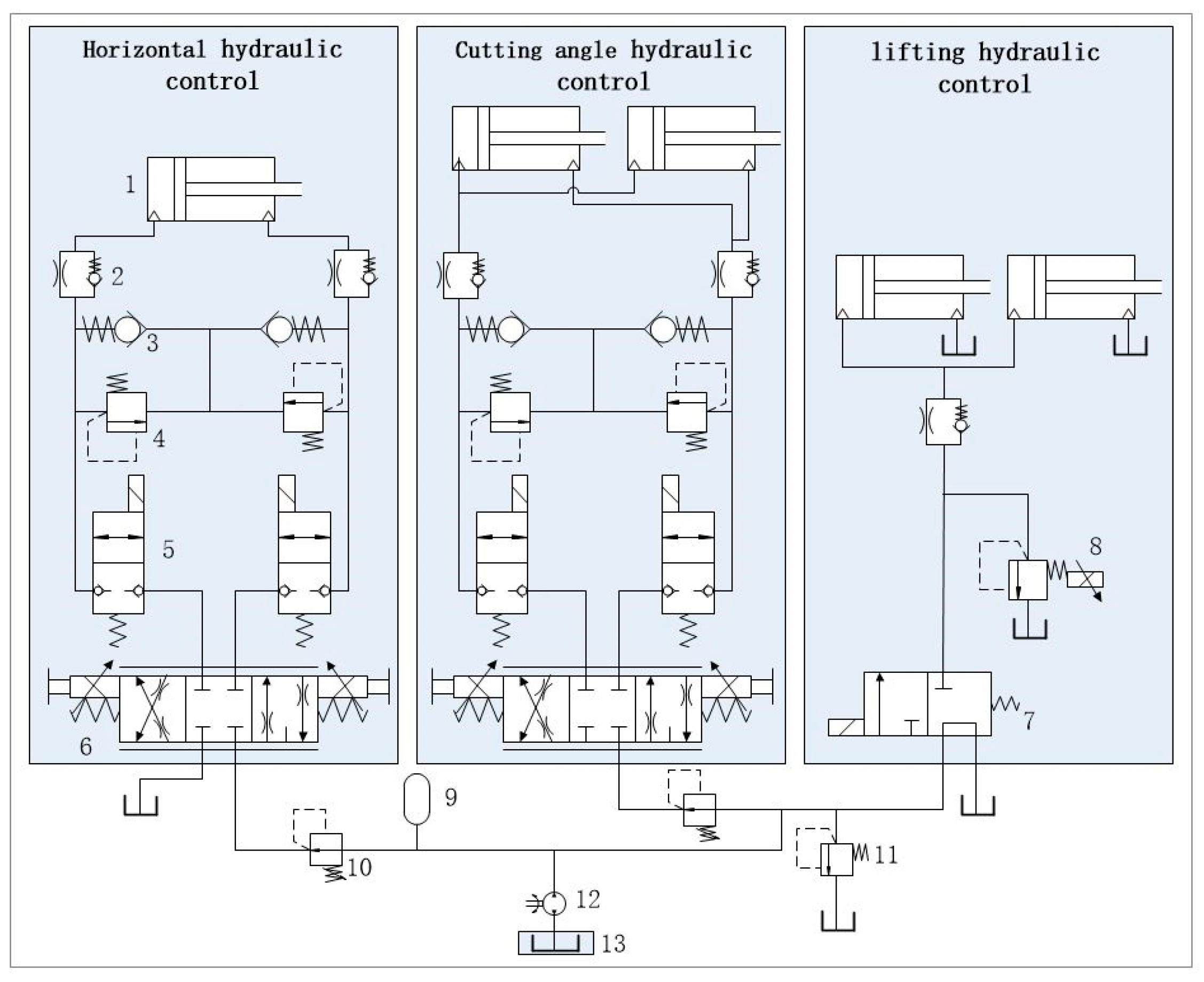
  • According to the profiling control strategy, an adaptive profiling hydraulic control system for the header suitable for hilly and mountainous areas is designed. It mainly consists of a profiling mechanism, a sensor unit, a profiling adjustment device, an adaptive controller, and a hydraulic drive device. The profiling mechanism and the sensor unit can sense and collect real-time information about the uneven field terrain. The hydraulic drive device controls the on–off of the solenoid valve through the electrical signals transmitted by the adaptive controller, thereby controlling the profiling adjustment device to perform accurate, stable, and real-time profiling of the header.
  • The developed system is subjected to simulation and field tests. The results show that the adaptive profiling control system is highly accurate and stable and can achieve horizontal profiling. This system improves the intelligence level of the grain combine harvester to a certain extent. It will also have practical applications in other agricultural machinery.

2. Materials and Methods

2.1. Adaptive Conformal Adjustment Mechanism Design

According to the grain combine harvester operation law design, as shown in Figure 1, the imitation grain header adaptive adjustment mechanism mainly consists of a vertical lifting hydraulic cylinder, bridge, cutting angle adjustment hydraulic cylinder, adjustment device, horizontal swing hydraulic cylinder, header, angle sensor, and imitation mechanism. As the key component of the control system, the adjusting device connects the header with the bridge dynamically to realize the swinging of the header in the horizontal direction through the horizontal swinging hydraulic cylinder and the adjustment of the angle of the cutting angle through the cutting angle adjusting hydraulic cylinder to realize the adjustment of the angle of the reciprocating cutter. The vertical lifting hydraulic cylinder is articulated with the bridge to realize the vertical lifting movement of the header.
The profiling mechanism mainly consists of a profiling rod, a fixed bracket, a torsion spring, a driving rod, a connecting rod, and a sensor driving plate [18]. We connect the profiling rod and the driving rod by bolts and hinge them on the fixed bracket of the profiling rod. We install the torsion spring between the profiling rod and its fixed bracket, and the torsion spring ensures that the profiling mechanism is in contact with the ground to collect ground information. The angle sensor mainly collects the ground information, the real-time state of the header, and the height of the center of the header from the ground and transmits the collected information to the controller in the form of electric signals. Through the above-designed adaptive adjustment mechanism of the profiling grain header, the profiling header of the grain combine harvester conducts real-time profiling during the harvesting operation.

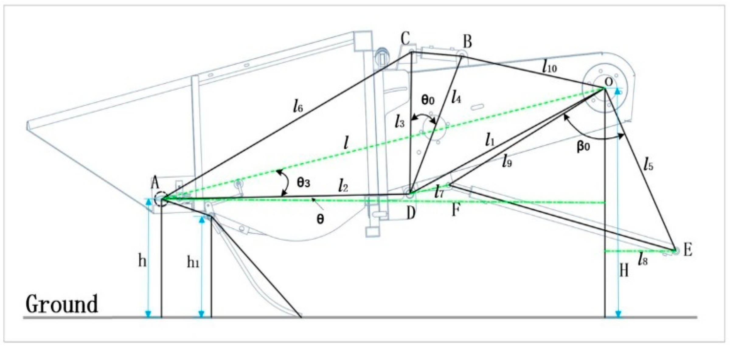
2.2. Modeling of Adaptive Conformal Adjustment Mechanisms

Kinematic analysis is a branch of mechanics that describes the law of change in the position of an object over time, based on the study of the motion of a mass or a rigid body; the study of the motion of an object does not involve the external forces on the object and only studies the motion response caused by these forces [19,20]. We simplify the adaptive affine adjustment mechanism as a fixed-axis rotating rigid body around the O point, in which the adjustment of the cutting angle of the reciprocating cutter is simplified as a fixed-axis rotating rigid body around the D point. The imitation of the grain header in the horizontal direction is simplified as a fixed-axis rotating rigid body around the O 1 point. The following were established: the imitation of the header in the vertical direction of lifting and lowering, the horizontal direction of rotary oscillation, and the front and back directions of rotary floating; three degrees of freedom of the motion relationship; the height of the cutter from the ground; the cutting angle; and the hydraulic cylinder expansion and contraction amount of the motion relationship. The simplified model of the adaptive profiling adjustment mechanism of the profiling grain header is shown in Figure 2.

2.2.1. Vertical Lifting Motion and Cutting Angle Adjustment

The cutting angle and vertical movement of the imitation grain header are controlled by the cutting angle adjustment hydraulic cylinder and the vertical lifting hydraulic cylinder expansion and contraction, respectively. O point is the dynamic connection point between the over-axle and the machine body to realize the vertical lifting and lowering of the imitation grain header; A point is the foremost part of the reciprocating cutter’s movable blade; D point is the dynamic connection point of the header and the bridge, realizing the adjustment of the cutter angle of the imitation grain header; B point and E point are the fixed articulation points of the cutting angle adjusting hydraulic cylinder and the vertical lifting hydraulic cylinder, respectively; and F point and C point are active articulation points. Then, the cutting angle adjustment hydraulic cylinder telescoping length L 1 and lifting hydraulic cylinder telescoping length L 2 through the cosine theorem can be directly expressed as follows:
L 1 = l 3 2 + l 4 2 2 l 2 l 3 cos θ 0
L 2 = l 5 2 + l 9 2 2 l 5 l 9 cos β 0
The relationship between θ 0 , β 0 , and l can be derived by using the following geometric relationships:
θ 0 = cos 1 l 1 2 + l 2 2 l 2 2 l 1 l 2 cos 1 l 2 2 + l 3 2 l 6 2 2 l 2 l 3 cos 1 l 1 2 + l 4 2 l 10 2 2 l 1 l 4
β 0 = π 2 θ + θ 3 cos 1 l 1 2 + l 2 l 2 2 2 l 1 l cos 1 l 1 2 + l 9 2 l 7 2 2 l 1 l 9 + sin 1 l 8 l 5
Moreover, l , as an intermediate quantity between the change in the angle of the cutter and the change in the vertical lift motion, can be expressed as follows:
l = H h sin θ + θ 3
where θ is a corresponding cutting angle given for different crops; θ 3 is the real-time angle data of the reciprocating cutter’s moving blade relative to the ground and collected by an angle sensor; h is a given stubble height of the crop to be harvested (the distance from the ground to the tip of the moving blade of the reciprocating cutter); and H is the distance from the point where the overbridge meets the body to the ground.
By substituting the parameters of the designed adaptive adjustment mechanism of the profiled grain header into the above relations and by substituting the relations (3), (4), and (5) with (1) and (2), one can obtain the relationship equation between the lifting movement of the imitation grain header in the vertical direction, the cutter angle adjustment hydraulic cylinders L 1 and L 1 , and the height of the header. The resulting expression is obtained:
L 1 = 0.67 1.21 cos cos 1 0.201 0.94 h sin θ + θ 3 2 0.199 2 °
L 2 = 1.86 1.52 cos 90.43 ° θ θ 3 cos 1 4.09 sin θ + θ 3 0.94 h + 5.32 0.94 h sin θ + θ 3

2.2.2. Horizontal Rotary Oscillating Motion

The heights h l and h r of the left and right sides of the header from the ground mainly determine the rotary swing of the profiling grain header in the horizontal direction, where H 1 is the distance between the center of the profiling rods on the outside of the profiling mechanism mounted on the bottom left and right sides of the header, γ is the horizontal angle of the header from the ground (i.e., the angle of change of the header from the level of the table), and γ 1 is the initial angle of the fixed mounting seat of the hydraulic cylinder from the point of rotation and the movable hydraulic cylinder at the time when the header is at the horizontal position. γ 1 is the initial angle of the hydraulic cylinder fixed mount from the rotation point and the hydraulic cylinder movable articulation point in the horizontal position of the cutting platform, L 3 is the initial length of the horizontal swing hydraulic cylinder, and L 4 is the adjusted length of the horizontal swing hydraulic cylinder.
According to the simplified model of Figure 3, the relationship between γ and h l and h r can be obtained as a kinematic modeling of the regulating mechanism in the horizontal direction.
γ = tan 1 h l h r H 1
The adjusted hydraulic cylinder length L 4 can be further obtained from the cosine theorem as follows:
L 4 = l 11 2 + l 12 2 2 l 11 l 12 cos γ 1 γ
Then, by substituting the parameters of the designed adaptive adjustment mechanism of the profiled grain header into the above relationship an equation representing the relationship between the change amount of the transverse hydraulic cylinder L and the heights of the left and right sides of the header, h l and h r , can be obtained via the following expression:
L = L 4 L 3 = 1.0946 1.037 cos tan 1 h l h r 1.74 46 ° 0.607

2.3. Overall Design of Adaptive Profiling Control System

2.3.1. Analysis of Affine Control Strategies

The profiling mechanism, as the source of the input signal of the control system, correlates with the amount of change in the profiling angle ω and the amount of change in the height of the ground h and the angle of rotation α of the angle sensor in the harvesting operation carried out by the grain harvester. According to the motion characteristics of the profiling mechanism, the profiling rod is dragged during the forward movement of the harvester. It will rotate under the action of the support force of the undulating terrain, generating the profiling angle ω . After a particular slope, the motion state is shown in Figure 4a [21].
By constructing a parallelogram in the coordinate system, the relationship equation between the change in height h and the change in the affine angle ω for the back and forth movement can be expressed as follows:
h = 2 l sin ω 2 cos ω 2 sin 1 h 1 m
Also, according to the position of the profiling mechanism mounted on the header, the relationship between h and h 1 is shown in Figure 4a.
h 1 = h sin 18 °
where h is the given stubble height, and m is the effective imitation length of the imitation bar.
The process of acquiring the angle signal of the affine mechanism by the affine angle sensor can be viewed as a mechanism with two links, as shown in Figure 4b. The articulated four-link mechanism A B C D can be viewed as a closed vector polygon where O C , C B , O A , and A B are vectors of each component. According to Ni Y.’s [6] study, the affine angle ω will be defined as a positive value in the x-axis counterclockwise and expressed in complex form as follows:
l O C e i π 3 + ω + l C B e i σ 6 = l O A + l A B e i α
where π / 3 is the fixed angle between the drive rod and the profiling rod, σ 6 is the angle between the connecting rod and the line connecting the fixed center of the profiling rod and the center of the sensor pendulum, and α is the sensor acquisition angle (the angle between the pendulum and the line connecting the fixed center of the profiling rod and the center of the sensor pendulum). By expanding this equation through Euler’s formula, the following expression is obtained:
l O A 2 + l A B 2 + l O C 2 l C B 2 + 2 l O A l O B cos α l O C cos π 3 + ω 2 l A B l O C cos α π 3 ω = 0
We obtain the basic parameters of the profiling mechanism used in this paper by substituting them into the above equation.
4050 cos π 3 + ω + 13,500 cos α π 3 ω 13,860 cos α = 56,134
As a result, the angle sensor will collect the cutting angle θ 3 ; the sensor angles α r and α l on the left and right sides of the header; analyze and compare the current state of the header by the adaptive affine algorithm written in the above principle; calculate the actual heights of the current left and right sides of the header, h l and h r ; and analyze the results by using the following expression:
h l = h h r h r = h h l
The result is transmitted as an electrical signal to the solenoid reversing valve, which drives the profiling hydraulic cylinder, adjusting the header’s profiling so that it is always parallel to the ground.
According to the above analysis, before the grain imitation header carries out field harvesting operations, the operator initializes the working state of the header by manually inputting the stubble height h of the crop to be harvested and the cutting angle θ of the cutter. In carrying out the harvesting operation, the angle sensor installed between the header and the overbridge collects the cutting angle θ 3 in real-time; the profiling mechanism installed at the bottom of the header profiles the terrain anywhere and determines the terrain condition by the angle between the profiling rod and the horizontal plane; the profiling angle sensors are installed at the two sidewalls and collect the state information of the profiling mechanism in real time (the profiling angles ω l and ω r ) and transmit this information through an electrical signal to the controller. The controller analyzes the algorithm after receiving the signal and then adjusts the header according to the control strategy of the profiling header, as shown in Figure 5.

2.3.2. Analysis of Hydraulic Drive Systems

As shown in Figure 6, the hydraulic drive system mainly includes a primary circuit and three sub-circuits. The primary circuit contains hydraulic pumps, safety valves, and accumulators, and the sub-circuits are mainly composed of lifting hydraulic cylinders, front and rear floating hydraulic cylinders, and horizontal swing hydraulic cylinders, which are automatically controlled by adaptive control algorithms. The horizontal swing cylinder and the front and rear floating hydraulic cylinders are controlled by a three-digit four-way electromagnetic reversing proportional valve to control the horizontal rotation of the profiling table and the adjustment of the front and rear cutting angles. Moreover, the lifting hydraulic cylinder is controlled by a two-digit three-way electromagnetic reversing proportional valve to control the vertical lifting and lowering of the profiling table [22]. Considering the harsh working environment of the copycat header, the circuit is designed with a pressure-reducing valve, safety valve, and buffer valve to reduce the impact and pulse generated by the hydraulic system, effectively reducing vibration and noise. The primary role of the one-way relief valve is to improve the stability of the hydraulic system; when the system pressure exceeds the pressure value set by the one-way relief valve, the valve port opens, the oil overflows back to the tank, thus restricting the further increase in system pressure and playing a protective role [23]. In addition, the accumulator in the hydraulic system can optimize the response time and stability of the hydraulic circuit by adjusting the volume and pressure of the stored pressurized fluid [24]. Grain combine harvester in the process of harvesting operations, according to the received profiling mechanism and the cutting platform, sends the signal for calculation and comparison, and then the results of the calculations in the form of electrical signals are transmitted to the three hydraulic circuit solenoid valves. Furthermore, the controller solenoid valves are turned on and off to regulate the expansion and contraction of the hydraulic cylinders, and the profiling of the header platform is controlled with the ground profiling.

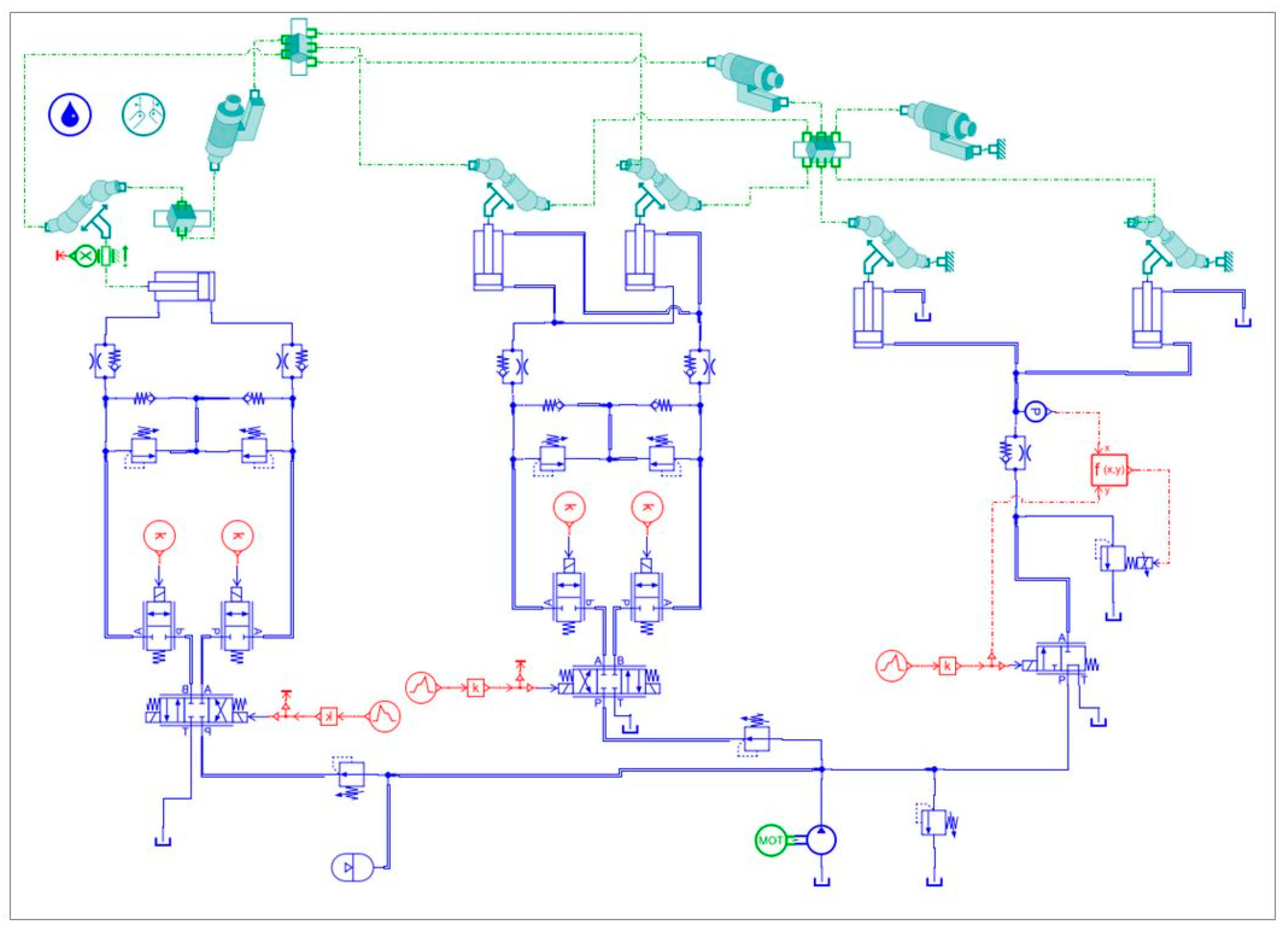
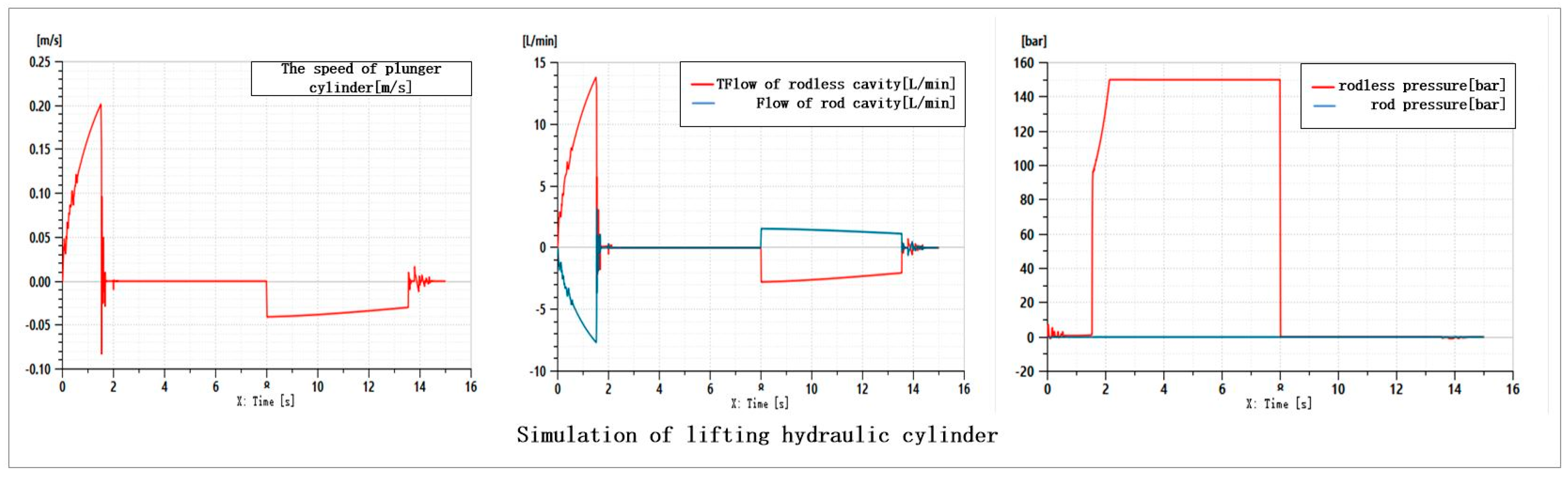
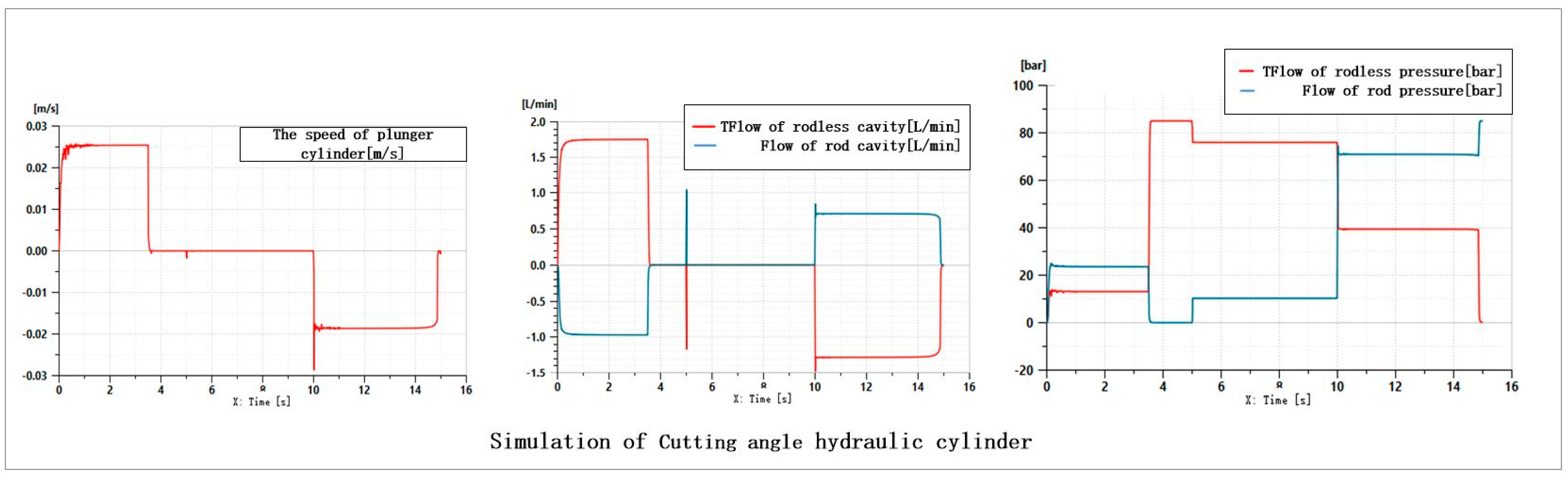
2.3.3. Simulation and Analysis of Hydraulic Systems

In this study, the simulation modeling of the cutter imitation hydraulic system was carried out using the Amesim2404 software, as shown in Figure 7. The operating parameters of each hydraulic component are set according to the data of the header hydraulic pipeline supporting the Lovol GM100, the harvester’s working speed, and the profiling header’s response time. The simulation results show that when the displacement of the hydraulic pump is set to 25 cc/rev, the motor speed is set to 1500 rev/min, the opening pressure of the safety valve is set to 160 bar, the flow rate gradient is set to 50 L/min, the initial pressure of the accumulator is set to 90 bar, and the volume is set to 0.8 L, the system reaches its optimal state.
The three-dimensional digital model is imported into the software, and the hydraulic module and the 2D mechanical module are used for co-simulation analysis. The motion laws of the header lifting plunger cylinder, the horizontal swing plunger cylinder, and the front–rear floating plunger cylinder are analyzed, and the dynamic performance of the hydraulic system is evaluated.

Vertical Elevation of the Header Imitates Rows

According to the simulation results shown in Figure 8, it can be seen that during the period of 0–3 s, the two-position three-way solenoid valve is energized, the left position works, the rodless chamber of the plunger cylinder is fed with oil, the rod chamber is discharged with oil, and the plunger rod is made to extend the state. Moreover, the current increased from 0 to 38 mA, the valve port opening gradually increased, the incoming flow rate steadily increased, and the speed of the plunger rod movement steadily increased. Because the plunger rod stroke is 200 mm, at 1.53 s, when the plunger rod extends to the head, the piston rod displacement remains at 200 mm, the speed reaches 0 m/s, and the flow rate becomes zero because of the structure of the movement process. There is a certain degree of inertia and a sudden change in speed, so at this time there is an impact on the plunger rod, resulting in a certain amount of oscillation in the flow rate and speed.
When the plunger rod moves to the end of the stroke, the flow rate drops to zero, but at this time, the highpressure oil provided by the hydraulic pump is still connected to the rodless chamber of the plunger cylinder, so the pressure will continue to increase. Then, the system pressure rises, the accumulator starts to charge until 2.16 s, the system pressure reaches 150 bar (reaching the set pressure of the system safety valve), the safety valve opens, and the system pressure stabilizes at 150 bar.
During 3–8 s, the two-position three-way solenoid valve is de-energized, and the unloading valve is in working condition; at this time, the rodless chamber of the lifting piston cylinder is disconnected from the primary oil circuit, and the pressure of the rodless chamber is 150 bar, which is not higher than the setting value of the unloading valve of 150 bar. Therefore, the pressure of the rodless chamber stays unchanged, there is no change in the displacement of the piston rod, and the flow rate and speed are zero.
During 8–15 s, the two-position three-way solenoid valve is de-energized, the unloading valve is unloaded, and the rodless chamber of the lifting piston cylinder is directly connected to the oil tank with the pressure of 0 bar. At this time, under the action of gravity, the piston rod starts to retract, due to the one-way speed control valve in the circuit, and the existence of the pressure drop in the flow of the unloading valve ensures that the speed of the piston rod retraction is not higher than 0.04 m/s. Moreover, the flow of the rodless chamber goes out and the rod chamber is sucked into the hydraulic oil from the oil tank. In 13.57 s, when the plunger rod is completely retracted, the speed suddenly changes to 0. Due to the inertia of both the oil and the structure, the plunger rod’s speed and the plunger cylinder’s flow pressure obtain a certain degree of oscillation.

Header Front and Back Floating Imitation Line

According to the simulation results shown in Figure 9, it can be seen that during the period of 0–5 s, the correct position of the three-position four-way directional valve is energized, the rodless chamber of the front and rear floating plunger cylinders is fed with oil, the rod chamber is discharged with oil, and the plunger rod is in an outstretched state; the current is increased from 0 to 40 mA and the valve port opening is gradually increased, due to the larger overcurrent area of the valve port. The flow rate of the incoming piston cylinder is in the saturated state at first; there exists a little overshooting at the same time and the speed has some fluctuations. After stabilization, the rodless chamber pressure is at 13.1 bar, the rod chamber pressure is at 23.58 bar, and the plunger rod movement speed is stable at 0.0254 m/s. Due to the plunger rod stroke of 90 mm, the plunger rod extends to the head at 3.5 s, and then the piston rod displacement is kept at 90 mm. The speed is 0 m/s and the flow rate is zero. In the 3.5–5 s period, the three–four-way speed regulating valve is more significant, the three-way four-way speed regulating valve is smaller, and the incoming flow rate is saturated at the beginning. During the period of 3.5–5 s, the right position of the three-position four-way directional valve is energized. The plunger rod moves to the end of the stroke. However, at this time, the high-pressure oil supplied by the hydraulic pump is still connected to the rodless chamber of the plunger cylinder, so the pressure will continue to rise, and then, in turn, the overall system pressure rises. The pressure of the rodless chamber of the plunger cylinder is stabilized at 85 bar due to the setting value of the decompression valve in the circuit being 85 bar.
During the period of 5–10 s, the three-digit four-way reversing valve loses power, the reversing valve returns to the center, and the front and rear floating circuits reach the state of pressure preservation. At this time, the lifting plunger cylinder rodless chamber is disconnected from the main oil circuit, and the front and rear floating plunger rods tend to be pulled out by gravity. Moreover, the pressure of the rodless chamber is stabilized at 75.9 bar, the pressure of the rodding chamber is stabilized at 10.27 bar, and the pressure of the plunger cylinder rodless chamber is stabilized at 10.27 bar, due to the setting value of the buffer valve in the circuit being 90 bar. As the buffer valve in the circuit is set at 90 bar, the buffer valve cannot be opened, so there is no oil flow in the plunger cylinder; the speed of the plunger rod is 0 m/s and the flow rates of the rodless chamber and the rod chamber are both 0 L/min.
During the period of 10–15 s, at the left position of the three-position four-way reversing valve, the rodless chamber of the lifting piston cylinder is directly connected to the oil tank. The rodded chamber is connected to the high-pressure oil circuit due to the existence of liquid resistance in the circuit; the pressure of the rodless chamber is stabilized at 39.44 bar and the pressure of the rodded chamber is stabilized at 70.91 bar. Then, the plunger rod starts to retract under the action of the pressure and the speed of the retraction is stabilized at 0.0186 m/s. The plunger rod speed is stabilized at 0.0186 m/s at the time of 14.88 s. At 14.88 s, the plunger rod is completely retracted, the speed changes to 0 m/s, the pressure in the rodless chamber is 0 bar. The pressure in the rod chamber rises to the setting value of the pressurized valve, 85 bar.

Horizontal Oscillation of the Header Imitates Rows

According to the simulation results shown in Figure 10, it can be seen that during the period of 0–5 s, the correct position of the three-position four-way reversing valve is energized, the rodless chamber of the horizontal oscillating piston cylinder is fed with oil, the rod chamber is discharged with oil, and the piston rod is stretched out; the current is kept at 20 mA, and the valve port is opened halfway. Due to the larger overcurrent area of the valve port and the smaller diameter of the one-way speed valve in front of the piston cylinder, the incoming flow rate is in a saturated state at the beginning, and there exists a bit of overshooting in the beginning. There are some fluctuations in velocity at the same time. While the speed has some fluctuations after stabilization, the rodless chamber pressure reaches 3.39 bar, the rod chamber pressure reaches 17.64 bar, and the plunger rod movement speed becomes stable at 0.0426 m/s. Since the plunger rod stroke is 245 mm, the plunger rod is in the middle position initially, and the plunger rod extends to the head at 2.91 s, at which time, the displacement of piston rod is kept at 245 mm, the speed at 0 m/s, and the flow rate at zero. The plunger rod is in the middle position and the speed is 0 m/s. The plunger rod is in the middle position. During the period of 2.91–5 s, the right position of the three-position four-way directional valve is energized. The plunger rod moves to the end of the stroke. However, at this time, the high-pressure oil supplied by the hydraulic pump is still connected to the rodless chamber of the plunger cylinder, so the pressure will continue to rise. Then, the system pressure rises due to the buffer valve in the circuit being set to 80 bar; the flow pressure gradient reaches 10 L/min/bar and the pressure in the rodless chamber of the plunger cylinder stabilizes at 82.5 bar. The rodless chamber pressure stabilizes at 82.5 bar, and the rod chamber pressure stabilizes at 2.47 bar.
During the period of 5–10 s, the three-digit four-way reversing valve loses power, the reversing valve returns to the center, and the front and rear floating circuits are in the state of pressure preservation; at this time, the lifting plunger cylinder rodless chamber disconnects from the main oil circuit, and the front and rear floating plunger rods obtain the tendency to be pulled out by gravity. Moreover, the pressure of the rodless chamber stabilizes at 81.9 bar, the pressure of the rodding chamber stabilizes at 1.9 bar, the setting value of the buffer valve in the circuit reaches 80 bar, the buffer valve obtains a stagnant ring due to friction, and the pressure gradient of flow pressure reaches 10 L/min/bar. Due to friction, the buffer valve has a hysteresis loop and the buffer valve keeps the closed trend state; at this time there is no oil flow in the plunger cylinder, the speed of the plunger rod reaches 0 m/s, and the flow rate of the rodless chamber and the rod chamber both reach 0 L/min.
During the period of 10–15 s, at the left position of the three-position four-way reversing valve, the rodless chamber of the lifting piston cylinder directly connected to the oil tank. The rod chamber is connected to the high-pressure oil circuit; due to the presence of liquid resistance in the circuit, the pressure of the rodless chamber stabilized at 29.35 bar and the pressure of the rod chamber stabilized at 77.01 bar. At this time, under the action of pressure, the plunger rod starts to retract and the retraction speed stabilizes at 0.025 m/s.
Based on the above analysis, the plunger and piston rod’s working speed curves are relatively stable. Although there is a slight overshoot at the beginning and the speed fluctuates to some extent, the system quickly stabilizes under the action of the accumulator, which has little impact on the movement of the plunger cylinder. Therefore, the design of the profiling header hydraulic system is reasonable.

3. Results

To verify the reliability of the adaptive control system of the profiling grain header, the designed profiling regulating mechanism and the control system were integrated in the Leivo GM100 grain combine harvester, as shown in Figure 11. Static and field tests were conducted in a wheat demonstration field in Huantai County, Zibo City, Shandong Province, China, in January 2024.

3.1. Static Test

The static test of the control system of the profiling cutter is mainly for calibration, to reduce the error of the field test, improve the safety of the operation, and verify the accuracy and stability of its control system on the flat ground. The test was conducted on the soil ground in two states of height and slope, and the combine harvester was at idle speed during the test. Different stubble heights were entered through the center console, and the time taken from when the signal was sent for adjustment to when the cutter was in a stable state was recorded. The distance from the front of the cutters on the left and right sides of the table to the ground was then measured using a meter tape. Five sets of data for the three motion states of rising, falling, and horizontal swinging of the header were tested, and their target values were set as 100 mm, 150 mm, 200 mm, and 250 mm.

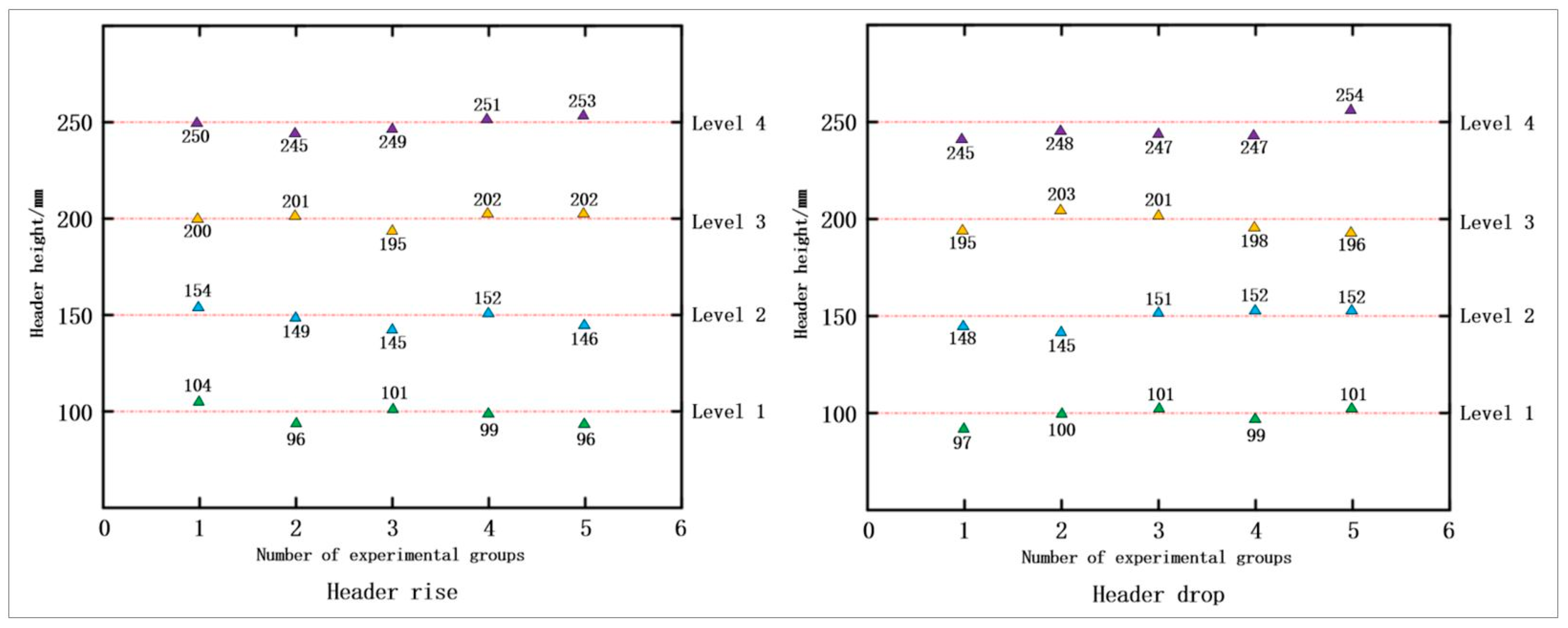
3.1.1. Header Rise and Fall Test

Figure 12 and Table 1 show the test results of this experimental header. The results of the control system for the regulation of the header profiling are consistent with the objectives of the repeatability test, and the fluctuation of the control error is slight. The errors are within the range of −5 mm to 5 mm. The MAEVs used for header profiling control are 2.5–3 mm and 1.5–3.5 mm, and their average relative errors are 1.69% and 1.43%, respectively. The average response time of the profiling system is in the range of 0.45–0.77 s and 0.65–0.84 s.
The test results indicate that the profiling cutter control system requires high accuracy and stability to control different stubble heights.

3.1.2. Header Slope Test

The slope test is performed on a mixed soil slope with a gradient of 30%. The height of the stubble and the angle of the cutter with the control system on were input; one side of the header (left or right) on the hill and the other one outside the slope were kept. Furthermore, when the cutter table is adjusted to a steady state, the distance from the front of the cutter to the slope and the angle of the cutter can be measured.
The cutter angle was set to 0° in all experiments, and according to the test results in Table 2, it can be seen that the results of the control system for the regulation of the cutter table profiling are consistent with the objectives of the repeatability test and that the control error fluctuates less. The errors are within the range of −5 mm to 5 mm. The MAEVs used for header profiling control are 2.5–3 mm and 2–3.5 mm, and their average relative errors are 1.61% and 1.59%, respectively. The average response time of the profiling system is in the range of 0.50–0.90 s and 0.60–0.90 s.
By analyzing the test results, we conclude that the profiling cutter control system is highly accurate and stable for different stubble heights on slopes.

3.2. Field Trial

To verify the stability and accuracy of the adaptive profiling cutter control system, the average stubble height L, the coefficient of variation of stubble C (V), and the height control accuracy of the cutter τ will be used as the evaluation indexes of the field test. L is used for evaluating the overall deviation of the actual stubble height from the set stubble height, C.V is used for assessing the stability of the system work, while τ is used for evaluating the distribution of the actual stubble height in the allowed error range of the ratio in order to assess the regulation accuracy of the system [25]. Before the test, wheat demonstration field with uneven and highly undulating terrain was selected. A benchmark was inserted every 20 m for the harvesting operation. Then, a tape measure was used to record and collect 50 sets of stubble heights after harvesting. Stubble height statistics for combine harvesters at 5, 7, 9, and 11 km/h speeds are shown in Figure 13.
The control results of the profiling cutter control system at different speeds can be determined by organizing and analyzing the data, as shown in Table 3.
This table shows that for different operating speeds, the mean value of stubble height has less error from the target value, and the absolute error is less than 2 mm. For the four sets of test data, the average of values is 4.53%, and the average of τ values is 94%, which indicates that the stubble height is basically stable, and the control algorithm of the profiling cutter has a good control effect on different harvesting speeds. During the harvesting operation, the speed influences the stubble height less and can effectively prevent the header from touching the ground.
According to the above experimental results, in the static and field tests under the control of different harvesting speeds and stubble heights, the designed adaptive adjustment mechanism and control strategy can make the profiling grain header realize adaptive profiling operation in harvesting operations and maintain the consistency of stubble cutting. The control system has high accuracy and stability during operation.

4. Discussion

The profiling grain header in this paper aims to solve the problem of inconsistent stubble heights when combine harvesters operate in complex environments. For instance, during harvesting operations in hilly and mountainous areas, the profiling grain header is required to profile in both the vertical and horizontal directions. This enables the header to maintain a horizontal position relative to the ground in real-time, ensuring consistent stubble heights and improving the harvesting quality.
In this study, the header profiling signal is acquired through profiling mechanisms installed on the left and right sides of the bottom of the header. During the movement of the profiling mechanisms, the two profiling rods make surface contact with the ground. However, in current research in this field, Li R. et al. installed the profiling rods at the two ends of the divider, resulting in line contact between the profiling rods and the ground [5,15]. The latter only considered soybean crops. For crops like rapeseed, which have short straws and complex relationships between plants, this line contact causes significant disturbances to the profiling rods [26]. In this research, an accumulator is installed in the hydraulic drive system to address the overshoot problem. This has not been used in previous research in this field and has only emerged in practical applications in the past two years.
The results of field experiments show that this adaptive control system’s accuracy and stability can meet the harvesting operations’ requirements. However, there are still discrepancies between the expected and experimental results. Based on an analysis of the environmental characteristics of the harvesting operations, it is known that the errors mainly stem from the coupled vibration and local vibration caused by the operation of the working components of the profiling header [27]. Therefore, the factor of header vibration will be considered in subsequent research.
The research findings of this paper will be applied to the intelligent operation of future combined harvesters. This can effectively reduce the labor cost of grain harvesting, enhance harvesting efficiency and crop quality, and reduce harvesting losses, playing a positive role in increasing production while reducing losses. This system will also be explored for extension to more types of agricultural machinery suitable for harvesting various crops. In addition, the profiling of the entire machine will affect the header’s profiling effect. Future research can be combined with the profiling of the vehicle chassis. By adopting control methods such as model reference adaptive control and integrating machine learning and artificial intelligence technologies, more precise adjustment of the header profiling can be achieved, thus improving crop harvesting efficiency and quality [28].

5. Conclusions

This paper proposes an adaptive control algorithm for the profiling grain header by the designed adaptive adjustment mechanism, and an adaptive profiling control system is developed based on this algorithm. The rationality of the design of the hydraulic control system of the profiling header was verified by Amesim simulation software, followed by static and field tests. The main conclusions can be summarized as follows:
(1) To solve the problem of accurate, stable, and reliable profiling control of the profiling grain combine harvester header under complex terrain conditions, this paper proposes a set of profiling header control strategies by analyzing the motion characteristics of the adaptive adjustment mechanism and builds a profiling hydraulic control system based on this strategy. Then, the optimal hydraulic parameters are obtained based on the hydraulic pipeline data of the existing models and Amesim simulation.
(2) Several field test sets were conducted at different speeds and header profiling heights. The results showed that at operating speeds of 5, 7, 9, and 11 km/h, the values of the imitation grain header were 3.2%, 3%, 6.1%, and 5.8%; the mean value is 4.53%, and the τ values are 94%, 96%, 94%, and 92% with mean values of 94% and 0. The developed adaptive control system for the profiled grain header has high accuracy and stability.
(3) Meanwhile, there are certain limitations in the research of this paper. Effective research has not been conducted on soil moisture levels and steeper terrains in hilly and mountainous areas. In future studies, we will conduct in-depth research across these two aspects to make the adaptive control system of the profiling grain header applicable to more agricultural harvesting machinery operating in complex working environments.

Author Contributions

Conceptualization, Y.N. and G.Z.; methodology, Y.N. and G.Z.; software, Y.N.; validation, Y.N., R.L. and W.L.; formal analysis, G.Z.; investigation, K.R.; resources, G.Z. and H.H.; data curation, Y.N.; writing—original draft preparation, Y.N.; writing—review and editing, Y.N.; visualization, Y.N.; supervision, G.Z.; project administration, G.Z.; funding acquisition, G.Z. All authors have read and agreed to the published version of the manuscript.

Funding

This research was supported by a grant from the Development of High Efficiency and Low Loss Single Longitudinal Axial Flow Threshing and the Separation Technology and Intelligent Flexible Threshing Device Project, from the College of Agricultural Engineering and Food Science, Shandong University of Technology, Grant No. 2021YFD200050204.

Institutional Review Board Statement

Not applicable.

Data Availability Statement

The datasets presented in this study are available from the corresponding author upon reasonable request.

Acknowledgments

Many thanks to all anonymous reviewers for their constructive comments on this manuscript. Meanwhile, we thank our research group for their investigation assistance in the preparation of this manuscript.

Conflicts of Interest

The authors declare no conflicts of interest.

References

  1. Deng, L.; Li, Y. Current situation and development trend of rice combine harvester in China. Res. Agric. Mech. 2001, 02, 4–6. [Google Scholar]
  2. Zhao, C.; Ma, C.; Li, J. Research status and prospects of mechanization technology for rice in hill and mountainous areas. J. Agric. Eng. 2005, 1, 1–11. [Google Scholar]
  3. Shen, Y.; Zhang, Y.; Liu, H. Research Review of Agricultural Equipment Automatic Control Technology. J. Agric. Mach. 2023, 8, 1–18. [Google Scholar]
  4. Lian, X.; Wang, J.; Zhu, Y. Research status analysis of key technology and loss of soybean harvester header. Chin. J. Agric. Mach. Chem. 2024, 45, 8–13. [Google Scholar]
  5. Wang, Q.; Meng, J.; Wen, K. Grain combine harveser header profiling control system development and testing. Comput. Electron. Agric. 2024, 183, 105907. [Google Scholar]
  6. Ni, Y.; Jin, C.; Chen, M.; Yuan, W.; Qian, Z.; Yang, T.; Cai, Z. A model for calculating the head height of a soybean harvester based on an earth-machine system with an adjustment system. Comput. Electron. Agric. 2021, 183, 105907. [Google Scholar] [CrossRef]
  7. Geng, A.; Zhang, M.; Zhang, J. Design and Experiment of Automatic Control System for Corn Header Height. J. Agric. Mach. 2020, 51, 118–125. [Google Scholar]
  8. Liu, W.; Luo, X.; Zeng, S. Performance test and analysis of the self-adaptive profiling header for ratooning rice based on fuzzy PID control. J. Agric. Eng. 2022, 38, 1–9. [Google Scholar]
  9. Wang, J.; Wang, Y.; Yu, W. Motion analysis and experimental study of automatic copying system and key components of residual film recovery machine. Xinjiang Agric. Sci. 2023, 60, 2842–2852. [Google Scholar]
  10. Jing, C.; Liu, G.; Ni, Y. Design and experiment of heauder profiling mechanism for combine harvester based on MBD-DEM coupling. J. Agric. Eng. 2022, 38, 1–10. [Google Scholar]
  11. Zhuang, X.; Li, Y. Header Height Control Strategy of Harvester Based on Robust Feedback Linearization. J. Agric. Eng. 2020, 51, 123–130. [Google Scholar]
  12. Lopes, T.; Magalhaaes, P.S.G.; Nobrega, E.G.O. Optimal header height control system for combines. BioSystems 2002, 81, 261–272. [Google Scholar] [CrossRef]
  13. Zhang, T.; Zhai, X.; Gao, J. Development of Adaptive Profiling System for Header of Fresh Corn Harvester which Reaping Both Corn Stalk and Spike. Agric. Eng. 2023, 13, 15–20. [Google Scholar]
  14. Wang, Z.; Yang, R.; Chen, D. Design of Header Profiling Height Control System Based on PID Regulation. Agric. Mech. Res. 2024, 46, 97–102. [Google Scholar]
  15. Li, R.; Xu, L.; Xu, X. Design and Simulation of Mechanical–hydraulic Combined Soybean Header Profiling Device. Agric. Mech. Res. 2024, 46, 60–65. [Google Scholar]
  16. Yang, R.; Wang, Z.; Shang, S. The Design and Experimentation of EVPIVS-PID Harvesters’ Header Height Control System Based on Sensor Ground Profiling Monitoring. Agriculture 2022, 12, 282. [Google Scholar] [CrossRef]
  17. Qian, J.; Ma, S.; Xu, Y. Experimental study on sugarcane stubble base-cutting mechanism. Biosyst. Eng. 2024, 245, 122–134. [Google Scholar] [CrossRef]
  18. Wei, L.; Che, Y.; Wang, F. Design and Experiment of the Ground Profiling Control System of Combine Header. Agric. Mech. Res. 2017, 39, 150–154. [Google Scholar]
  19. Luo, Y.; Liao, Z.; Shi, S. Design and Testing of a 2-DOF Adaptive Profiling Header for Forage Harvesters. Agronomy 2024, 14, 1909. [Google Scholar] [CrossRef]
  20. Ji, K.; Li, Y.; Li, G. Design and Test of Film Mulch Precision Planter for Turnips. Agric. Mech. Res. 2023, 45, 85–89+94. [Google Scholar]
  21. Zhao, L. Study on the Adaptive Control System of Sugarcane Harvester Based on Cutting Height Detection. Master’s Thesis, Changan University, Xian, China, 2022. [Google Scholar]
  22. Zhang, Z. Design and analysis of hydraulic lifting system of combine harvester cutting platform. Master’s Thesis, Shandong University of Science and Technology, Shandong, China, 2019. [Google Scholar]
  23. Yi, S.; Li, Y.; Li, Y. Design and test of hydraulic active profiling mechanism for high-speed no-till corn planter. J. Agric. Mach. 2024, 55, 110–120+130. [Google Scholar]
  24. Zhao, S.; Zhou, J.; Zhang, S. Simulation on position Overshoot of Hydraulic Cylinder Piston Based on AMESim. Chin. Hyd. Pneum. 2023, 47, 138–145. [Google Scholar]
  25. Liu, G.; Ni, Y.; Yang, T. Design and experiment of header height automatic control system for soybean harvester. Chin. J. Agric. Mach. Chem. 2023, 44, 155–160+2. [Google Scholar]
  26. Zhou, Y.; Luo, Y.; Liu, D. Designandexperimentofrapecutterin4LZ-4.0graincombineharvester. Chin. J. Agric. Mach. Chem. 2023, 44, 22–29+35. [Google Scholar]
  27. Yao, Y.; Song, Z.; Du, Y. Analysis of vibration characteristics and its major influenced factors of header for corn combine harvesting machine. Agric. Eng. 2017, 33, 40–49. [Google Scholar]
  28. Qi, M. Research on the Application of Intelligent Control Technology in the Header Height Control of Corn Harvesters. Agric. Dev. Equip. 2024, 09, 59–61. [Google Scholar]
Figure 1. Schematic diagram of the adaptive profiling adjustment mechanism. 1. Lifting hydraulic cylinder; 2. overbridge; 3. cutting angle adjusting hydraulic cylinder; 4. horizontal swinging hydraulic cylinder; 5. header; 6. angle sensor; 7. fixing bracket; 8. profiling rod; 9. sensor driving plate; 10. connecting rod; 11. driving rod; and 12. adjusting device.
Agriculture 15 00473 g001
Figure 2. Kinematic modeling of the regulating mechanism in the vertical direction.
Agriculture 15 00473 g002
Figure 3. Kinematic modeling of the regulating mechanism in the horizontal direction.
Agriculture 15 00473 g003
Figure 4. (a) Kinematic modeling of affine mechanisms. (b) Computational model for conversion of affine angles to sensor acquisition angles.
Agriculture 15 00473 g004
Figure 5. Leveling strategy for profiling grain header control system.
Agriculture 15 00473 g005
Figure 6. Schematic diagram of the hydraulic system of the imitation row grain header. 1. Double-acting hydraulic cylinders; 2. one-way speed control valves; 3. check valves; 4. safety valves; 5. switching valves; 6. three-position four-way solenoid operated proportional valves; 7. two-position three-way solenoid operated proportional valves; 8. solenoid relief valves; 9. accumulators; 10. decompression valves; 11. buffer valves; 12. hydraulic pumps; and 13. oil tanks.
Agriculture 15 00473 g006
Figure 7. Joint simulation modeling of hydraulic systems. Hydraulic module and 2D mechanical module for joint simulation are used to analyze the header lifting ram cylinder, horizontal oscillating ram cylinder, and front and rear floating ram cylinder motion patterns, and evaluate the dynamic.
Agriculture 15 00473 g007
Figure 8. Lifting hydraulic cylinder simulation analysis results.
Agriculture 15 00473 g008
Figure 9. Cutting angle hydraulic cylinder simulation analysis results.
Agriculture 15 00473 g009
Figure 10. Horizontal hydraulic cylinder simulation analysis results.
Agriculture 15 00473 g010
Figure 11. Prototype field test and data collection.
Agriculture 15 00473 g011
Figure 12. Static test results for profiling cutter elevation statistics.
Agriculture 15 00473 g012
Figure 13. Statistical results of field trial data.
Agriculture 15 00473 g013
Table 1. Analysis of static test results for profiling cutter elevation.
StateHeader Height (mm)Max. AEV (mm)Min. AEV (mm)MAEV (mm)MRE (%)ART (%)
Up100412.52.830.52
1505132.150.45
200502.51.000.77
250502.50.800.60
Down100301.51.220.70
150412.51.620.84
2005131.510.65
250523.51.370.72
Table 2. Analysis of static test results for profiling cutter slope.
StateHeader Height (mm)Max AEV (mm)Min AEV (mm)MAEV (mm)MRE (%)ART (%)
Left
deflection
100422.62.580.62
150502.41.650.55
200422.81.390.87
2505020.810.56
Right
deflection
1004022.040.63
150412.61.760.78
2004131.510.71
250512.61.030.82
Table 3. Analysis of statistical results of field trial data.
No.Vehicle Travel Speed (km/h)Stubble Height L (mm)C.V (%)Τ (%)SSR (%)
15198.223.2940
27199.683.0960
39199.146.1940
411199.405.8920
Disclaimer/Publisher’s Note: The statements, opinions and data contained in all publications are solely those of the individual author(s) and contributor(s) and not of MDPI and/or the editor(s). MDPI and/or the editor(s) disclaim responsibility for any injury to people or property resulting from any ideas, methods, instructions or products referred to in the content.

