Article

Design and Test of Straw Crushing and Spreading Device Based on Straw Mulching No-Tillage Planter

1
College of Engineering, Northeast Agricultural University, Harbin 150030, China
2
School of Mechanical Engineering, Changzhou Institute of Technology, Changzhou 213032, China
3
School of Information Engineering, Huzhou University, Huzhou 313000, China
*
Authors to whom correspondence should be addressed.
Agriculture 2025, 15(23), 2404; https://doi.org/10.3390/agriculture15232404
Submission received: 21 October 2025 / Revised: 10 November 2025 / Accepted: 18 November 2025 / Published: 21 November 2025
(This article belongs to the Section Agricultural Technology)

Abstract

To address issues such as slow soil temperature recovery and delayed sowing periods caused by straw mulching in the cold regions of northern Heilongjiang Province, this study designed a straw crushing and scattering device compatible with the 2BMFJ series no-till planters, aiming to achieve moderate straw fragmentation and uniform distribution. By establishing mathematical models for the straw pick-up, crushing, and scattering processes, key parameters affecting the device’s performance were determined. Utilizing the discrete model of EDEM 2018 software virtual simulation experiments were conducted based on response surface methodology. The test factors included the blade angle of the crushing long blade, the edge thickness of the crushing long blade, the weight of the crushing long blade, and the rotational speed of the crushing long blade. The performance evaluation indicators were the straw pick-up rate, straw crushing rate, power consumption, and inter-row straw coverage consistency. The optimal parameter combination was identified to be a blade angle of 25°, an edge thickness of 1.25 mm, a weight ranging from 0.35 to 0.41 kg, and a rotational speed between 1400 and 1750 r/min, resulting in a straw pick-up rate of 83%, a straw crushing rate of 84%, power consumption of 6.8 KW, and a straw cleaning consistency between rows of 75%. Field test results indicated that the straw pick-up rate reached 87.2%, the straw crushing rate achieved 81.5%, power consumption was 7.7 kW, and the straw cleaning consistency between rows attained 79.3%. The deviations from simulation results were within acceptable limits. This equipment can effectively complete straw crushing and scattering operations, thereby creating favorable seedbed conditions.

1. Introduction

Conservation tillage is a contemporary agricultural system focused on enhancing soil health and improving grain quality and efficiency, thereby facilitating coordinated economic, social, and ecological sustainable development [1,2,3,4]. As a vital aspect of this technology, straw mulching and incorporation effectively enhance soil structure, mitigate wind and water erosion, and decrease reliance on chemical fertilizers and pesticides [5,6,7,8]. Among these methods, the quality of straw crushing and mulching serves as a critical indicator for assessing the effectiveness of incorporation [9,10,11,12]. No-till planters equipped with straw mulching capabilities integrate seedbed preparation prior to sowing with straw mulching afterward, achieving complete straw incorporation while maintaining seeding quality. However, during the spring planting season in northern Heilongjiang Province, the low temperature of the cultivated layer, combined with the full coverage of straw on the surface, impedes soil temperature recovery, resulting in delayed emergence, diminished seedling quality, and yield losses. To mitigate this issue, it is essential to appropriately crush the straw while ensuring a controllable spreading distance. The crushed straw can be distributed on both sides of the ridge through the combined effects of spreading kinetic energy and wind force, thereby reducing coverage on the ridge top and increasing the contact area between the ridge surface and air/sunlight, which aids in heat dissipation and temperature elevation. Simultaneously, straw mulching on the sides of the ridge provides the dual benefits of returning organic matter to the field and functions such as water retention, evaporation suppression, and weed control.
Consequently, straw crushing and scattering technologies, along with the associated equipment, have emerged as a focal point of research within the field of agricultural engineering, garnering significant attention from scholars. Substantial research outcomes have been documented in this domain, as illustrated in Table 1. Kang et al. [13] developed a straw-covering rapeseed combined planter based on a combine harvester platform, which integrates an additional straw crushing and side-throwing device to improve the comprehensive utilization efficiency and operational continuity of the equipment. However, the integration of multiple functions results in a relatively complex structure, imposing higher requirements for manufacturing and maintenance. Zhang et al. [14] applied bionic principles to the design of crushing blades, developing a bionic serrated crushing blade modeled after the tooth profile of a blue shark, which significantly improved straw crushing efficiency and scattering uniformity. However, the wear resistance, service life, and operational stability of the bionic blade under harsh working conditions require further verification. Qin et al. [15] designed a straw crushing and scattering device for a straw-returning fertilizing and dibbling seeder, which maintains good machine passability while returning straw to the field. Nonetheless, the rearward-throwing method increases the risk of clogging when handling large volumes of straw. Wang et al. [16] developed a chopping-type corn stalk returner to address issues such as excessive surface straw after corn harvest in China’s double-cropping northern regions, a low qualified rate of crushing length with flail-type returners, and the subsequent impacts on no-till sowing. This innovation provides new insights into mechanized straw return technology. However, due to limitations in the working principle of the mechanical structure, the operational efficiency of the equipment still requires further improvement. Liu et al. [17] proposed a corn stalk crushing and returning method that features allometric counter-rollers and a dynamic dual-support structure, alongside the development of a supporting corn stalk returning device. This approach effectively enhances the qualified rate of stalk crushing. However, the use of single-stage counter-cutting necessitates relatively high rotational speeds for the returning blades, which in turn leads to increased power consumption. Jia et al. [18] designed a straw cutting blade for seeding devices, tailored to meet the agronomic requirements of no-till planting with both wide and narrow rows. They conducted a thorough design and optimization of the blade edge curve. However, the technology necessitates high environmental standards, which limits its widespread adoption. Through an analysis of existing technologies, it has been observed that research on straw crushing and scattering primarily focuses on machinery and equipment designed for straw crushing and returning. These machines execute both crushing and scattering simultaneously, necessitating an increase in spindle rotation speed to enhance their capacity for picking up, crushing, and scattering surface straw. However, they exhibit a low straw processing capacity per unit width and tend to scatter straw in the opposite direction of the machine’s movement, which results in relatively high coverage uniformity. Nonetheless, the operational principle of these machines leads to low efficiency and high power consumption. Some studies have attempted to integrate these functions into seeders or combine harvesters; however, they demonstrate insufficient adaptability to the conditions prevalent in northern cold regions of Heilongjiang Province, characterized by cold temperatures, heavy clay soils, short suitable sowing periods, and large straw volumes.
In summary, to address the challenges of slow soil temperature recovery and delayed sowing associated with no-till practices and straw mulching in cold regions, this study proposes a solution that involves moderate fragmentation of corn straw and the implementation of composite inter-row surface mulching using a no-till straw-mulching planter. The design integrates straw fragmentation and scattering devices, facilitating the simultaneous processing of straw and inter-row mulching during sowing. This approach aims to reduce the number of machinery passes required and minimize energy consumption. Additionally, mathematical models for straw pick-up, fragmentation, and spreading were developed to qualitatively analyze the effects of device structure and operational parameters on performance. A combined approach utilizing discrete element simulation and response surface methodology was employed to optimize parameter combinations, further validated through field tests.

2. Materials and Methods

2.1. Structure and Working Principle

Figure 1 illustrates the structural composition and operational principle of the straw-crushing and spreading device. It primarily consists of the spreading and regulating worm shell, the crushing and spreading blade shaft, the frame, and additional components. The straw no-till planter is equipped with clearing blade rollers that can operate within the width of the corn stover. It features a multi-stage transport system capable of distributing the straw to both sides. Below the crushing and spreading blade shaft, there exists a hinged working blade group comprising a long blade, a short blade, and a negative-pressure blade. The high-speed rotation of the long blade crushes the corn stover, which is subsequently transported back by the belt. The short blade, in conjunction with the airflow, lifts the crushed corn stover and directs it into the spreading regulating snail shell. The proximity between the inlet of the regulating shell and the crushing long blade primarily facilitates the moderate crushing of the corn stover. The crushed corn stover then accelerates along the spreading regulating shell due to the combined effects of inertial force and airflow. Upon reaching the outlet of the spreading regulating shell, the corn stover is scattered freely with its initial velocity, completing the scattering process. Some of the scattered corn stover, propelled by its inertial force, is transported to the ridge on the sown ground surface. When the corn stover is thrown onto the cultivated ground surface, it possesses a specific inertial force that causes some of the broken stover to move towards the sides of the raised ridge. The remaining stover that does not move towards the sides of the ridge is naturally dispersed by the wind, resulting in the formation of a layer of straw mulch between the ridges.

2.2. Crushing and Spreading Blade Shaft Design

Figure 1 illustrates the configuration of the crushing and spreading blade shaft. The primary element is the operating blade group, which serves the dual purpose of gathering straw and effectively crushing and transporting it. The working blade group is designed with a combined structure to minimize the vibration caused by the high-speed rotation of the crushing and spreading blade shaft. The working blade group is attached to the spreading blade roller using hinges. The working blade set consists of a long crushing blade, a short crushing blade, and a negative pressure blade. The primary function of the long crushing blade is to pick up, crush, and spread corn stover. The short crushing blade assists in these tasks and also supports the negative pressure blade. The negative pressure blade aids the long crushing blade in picking up corn stover, ensuring smooth entry into the device. Additionally, it increases the initial speed of crushed corn straw, thereby enhancing the overall crushing ability of the corn straw. Simultaneously, it may enhance the starting velocity of crushed corn stover, optimize the throwing distance, augment the velocity and volume of airflow at the throwing outlet, and effectively cover the stover between ridges.
The size of the working blade group’s rotary diameter significantly affects the dynamic balance of the crushing and spreading blade shaft. As the rotary diameter of the working blade group increases, the linear speed of the working blade group also increases, resulting in improved corn stover crushing. However, this increase in rotary diameter also leads to increased vibration of the crushing and spreading blade shaft and higher power consumption. Currently, the rotational diameter design range for domestic and international corn stover crushing devices is 560 to 700 mm [19]. In order to accommodate the increased volume of straw being delivered by the straw no-till planter, a rotary diameter of 700 mm is selected for the working blade group.
The velocity of the tip of the crushing long blade is a crucial aspect that influences the efficiency of corn stover crushing. This velocity is determined by the speed of the crushing and spreading blade shaft, as well as the rotary diameter of the crushing long blade. Based on the experimental investigation, it has been shown that the optimal cutting linear velocity for crushing corn stover falls between the range of 30–48 m/s, and this range aligns with Equation (1). By incorporating the established parameters into Equation (1), one may determine the optimal range for the speed of the crushing and spreading blade shaft, which falls between 1000 and 1500 (r/min).
v p = π n p D p 60
where vp is the corn stover crushing linear speed, m/s; Dp is the crushing long blade rotary diameter, m; np is the crushing and scattering blade shaft speed, r/min.

2.3. Work Process Analysis

2.3.1. Analysis of the Pick-Up Process

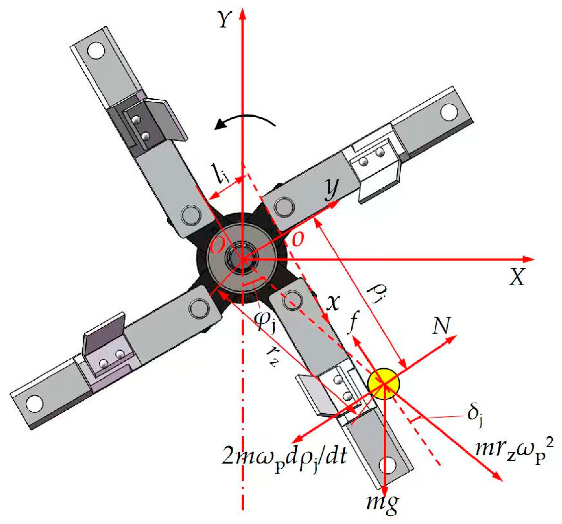
The corn stover picking process focuses on studying a simplified individual corn stover particle. The force acting on the particle is separated into two components: rotation with the crushing long blade and sliding along the edge of the crushing long blade, as seen in Figure 2. The corn stover is subject to many forces, namely its gravitational force, centrifugal force, Kohl’s force, edge surface support force, and friction force when sliding along the edge of the crushing long blade. To establish a fixed coordinate system XOY and a dynamic coordinate system XOY, the crushing and spreading blade axis rotation plane is used. The vertical line from O to the crushing long-bladed edge is considered the reference line. The pituitary foot, denoted as o, serves as the origin of the dynamic coordinates. The dynamic equations for corn stover can be derived as follows:
m d 2 ρ j d t 2 = m r z ω p 2 cos δ j + m g cos φ j δ j u 2 m ω p d ρ j d t m r z ω p 2 sin δ j + m g sin φ j δ j ρ j t = 0 = ρ j 0
where m is the straw mass, kg; ωp is the crushing and spreading blade shaft angular velocity, rad/s; ρj is the straw position, mm; rz is the straw turning radius, mm; δj is the working inclination angle, rad; µ is the friction factor; φj is the crushing blade angle, rad; ρj0 is the straw initial position, mm.
To obtain the minimal angular velocity of the corn stover during the outward movement of the crushing blade, Equation (2) needs to be rearranged to expand the power series and consider the first two derivatives.
ω min = 2 g μ D p sin δ j + 2 ρ j 0 cos φ j
Equation (3) reveals that the least angular velocity at which corn stover moves outward is influenced by the rotary diameter of the crushing blade, the friction factor, the working inclination, and the initial location of the stover. These factors have a negative correlation with the minimum angular velocity. Make sure that the angular velocity of the crushing and spreading blade shaft exceeds the minimum angular velocity required for the corn stover to move outward along the crushing blade. It allows the stover to be moved outward along the crushing blade edge after being picked up without interfering with the spreading of the stover.

2.3.2. Analysis of the Crushing Process

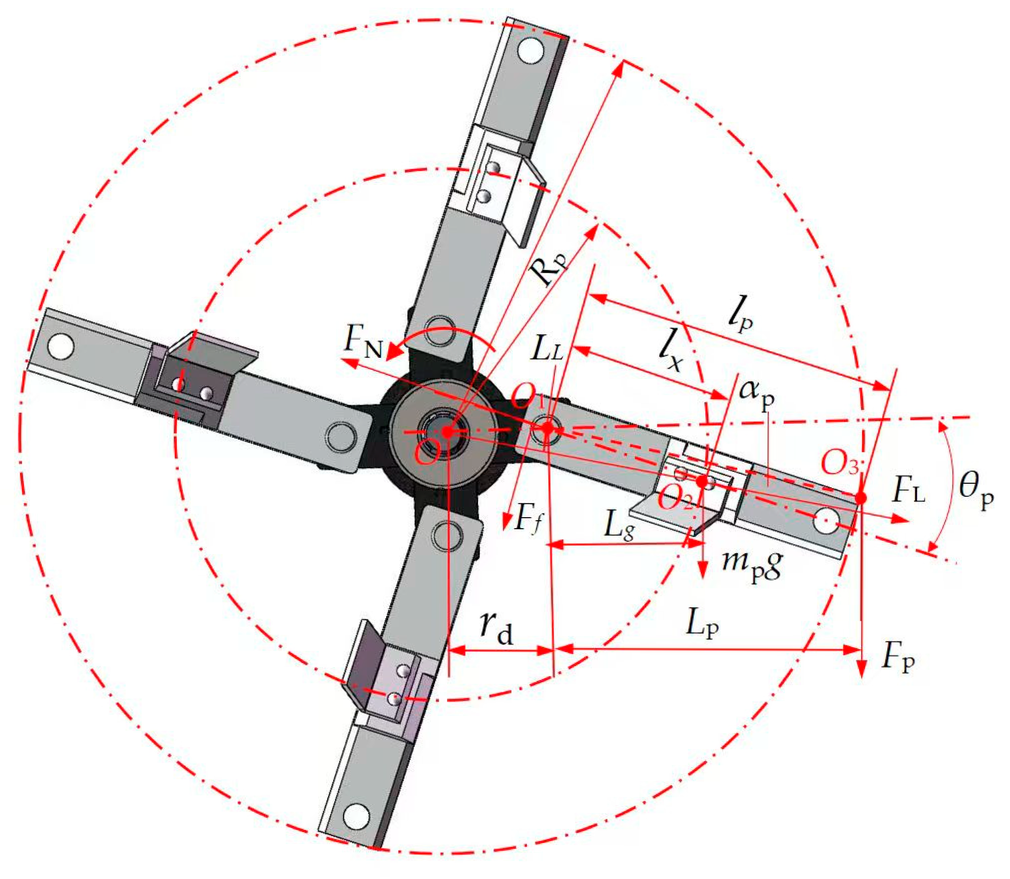
The working blade group remains in a radial unfolding state due to the articulated assembly with the spreading blade roller and the centrifugal force generated by high-speed rotation. However, when the working blade group crushes the corn stover, the cutting resistance causes a deviation angle to form between the blade group and the blade seat. By taking the rotating center of the spreading blade roller as the origin, a right-angle coordinate system is established. It is depicted in Figure 3. The force analysis of the crushing process of the long blade-crushing corn stover may be achieved using this coordinate system:
F p l p cos θ p α p m p l x sin θ p g + l p ω p 2 μ p F N r x = 0
where mp is the crushing long blade weight, kg; μp is the friction factor of blade seat and crushing blade; Fp is the crushing resistance, N; FN is the blade seat on the broken stubble blade support force, N; lp is the crushing long bladed length, m; lx is the center of mass of crushing long blade, m; rx is the radius of hole of blade seat, m; θp is the crushing deflection angle, (°); αp is the cutter body width angle, (°).
The process of crushing corn stover involves the high-speed rotation of a long blade, which results in the crushing. The friction resistance caused by the blade seat hole on the long blade is negligible, allowing us to simplify Equation (4) as follows:
tan θ p = F p l p m l x g + l p ω p 2
The crushing resistance of corn stover can be determined by using a long crushing blade to cut them. The crushing long blade is the subject of study, and the force exerted during the process of cutting corn stover is analyzed. If the research subject is an elastomer, the process of cutting stover using a long blade that crushes them can be divided into two stages: the stage of squeezing the stover with the crushing blade and the stage of cutting them into stalks. During the initial phase of corn stover crushing, the angled surface of the long crushing blade experiences both extrusion force and friction force from the corn stover. The extrusion force exerted by the corn stover on the angled surface of the blade can be divided into two forces, one acting horizontally and the other vertically. By conducting force analysis, it is evident that the combined force responsible for crushing corn stover using a long blade consists of the vertical pressure exerted by the crushing long blade angle, the vertical force resulting from the beveled pressure of the crushing long blade angle, and the vertical force caused by the friction of the crushing long blade angle. Thus, the required crushing force for crushing corn stover with a long blade can be determined.
F p = N p y + 2 m N p y c o t γ p - m 2 N p y + b p s p σ s
where Npy is the crushing long blade edge angle oblique pressure vertical component force, N; γp is the crushing long blade edge angle, (°); σs is the corn stover yield strength, MPa; bp is the crushing long blade edge thickness, m; sp is the blade length, m.
Equation (6) reveals the need to calculate the vertical upward force on the beveled surface of the crushing blade in order to ascertain the factors that influence the crushing force of corn stover. According to Hooke’s law, the stress of corn stover within the elastic range is equal to the strain multiplied by the modulus of elasticity. Additionally, the strain can be determined by measuring the deformation of the corn stover and comparing it to its original size. The force per unit length in the vertical direction of the crushing long blade edge beveled surface can be expressed as:
d N p y = E Δ h p h p tan γ p d Δ h p
where Δhp is the deformation in the direction of corn stover extrusion, mm; hp is the original size in the direction of corn stover extrusion, mm.
Integrating the left and right sides of Equation (7) and substituting it into Equation (6) yields.
F p = 1 + μ μ 2 E tan γ p Δ h p 2 2 h p + b p s p σ s
Equation (8) demonstrates that the corn stover crushing resistance is influenced by both the physical properties of the corn stover and the structural dimensions of the crushing long blade. Specifically, increasing the thickness and length of the crushing blade edge will result in higher crushing resistance.
Bringing Equation (8) into Equation (5) yields
tan θ p = 1 + μ μ 2 E tan γ p Δ h p 2 2 h p + b p s p σ s l p m p l x g + r d ω p 2
Analysis reveals that the effectiveness of corn stover crushing and picking up deteriorates when the crushing deflection angle of the long blade increases. Equation (9) demonstrates the correlation between the crushing deflection angle and various factors, including the crushing length of the long blade, the weight of the crushing long blade, the center of gravity position of the crushing long blade, the rotating radius of the blade seat, and the rotating angular velocity of the crushing long blade. Therefore, it is possible to decrease the angle of deflection caused by crushing. Operational efficiency and quality can be improved by decreasing the crushing deflection angle. This can be achieved by increasing the weight and rotational speed of the crushing blade, altering the position of its center of gravity, and reducing its length. It is important to avoid excessive angular speed while crushing with a long blade. A higher angular speed will result in a bigger centrifugal force, which can lead to increased power consumption, heightened vibration, and decreased machine reliability. Simultaneously, it is important to ensure that the weight of the crushing long blade is not excessive. A heavier blade would impose a greater working load on the machine, resulting in increased power consumption. The length of the crushing long blade should not be excessively short, as a shorter length would result in diminished effectiveness in picking up and receiving corn stover. By employing structural design, it is feasible to manipulate the position of the center of gravity of the crushing long blade in order to decrease the crushing angle.

2.3.3. Analysis of the Scattering Process

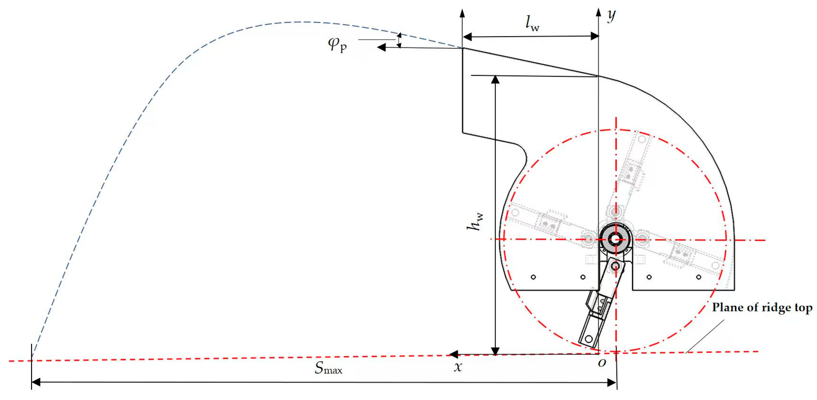
After being crushed, corn stover is propelled along the guiding plate by a combination of centrifugal force, inertia force, and airflow in the spiking regulating worm shell. The corn stover then moves through the air for a certain period before falling to the ground. The corn stover that becomes detached from the spiking regulating worm shell is considered a projectile. The analysis of the corn stover spiking process can be approached using projectile theory [20,21,22,23]. When disregarding the impact of natural wind, the rotation of corn stover, and the interaction between corn stover and soil, the only forces acting on corn stover as it moves through the air after detaching from the guiding plate are air resistance and gravity [24]. The corn stover-throwing process can be categorized into three types—stover up-throwing, flat-throwing, and down-throwing—based on the size and direction of the partial velocity in the vertical direction when the corn stover is detached from the guiding plate. This analysis focuses only on stover up-throwing, aiming to ensure that the distance of stover throwing is controllable and meets operational requirements. The coordinate system is defined by the point where the end of the worm shell’s surface intersects with the top of the ridge. The horizontal scattering direction of corn straw is taken as the positive direction of the x-axis, and the vertically upward direction is taken as the positive direction of the y-axis, as shown in Figure 4.
The corn stover is initially thrown upwards, and then, due to the combined effects of gravity and air resistance, it moves upwards along the positive y-axis for a certain distance. Afterward, it starts moving downwards along the negative y-axis until it reaches the surface of the top of the ridge. At this point, its velocity in the y-direction becomes zero. For a slow-moving projectile, there are typically two models that describe the relationship between air resistance and velocity: one where air resistance is proportional to the primary velocity and another where it is proportional to the secondary velocity [25,26]. This work employs a model where air resistance is directly proportional to the square of the velocity. The purpose is to derive the equations of motion for the process of tossing corn stover upwards. The sign of the air resistance coefficient is opposite to the direction of corn stover movement. Specifically, when the corn stover moves upward, the coefficient is 2, whereas when it moves downhill, the coefficient is 1 [27]. The equations of motion for the upward throwing of the corn stover can be integrated, resulting in the velocity expression (10) for the upward movement. Similarly, the kinematics equations can be derived for the landing of the stover.
v p x = v x 0 1 + C p v p 0 cos φ p t v p y = g C p tan arctan v p 0 sin φ p C p g g C p t
included among these:
0 t 1 g C p arctan v p 0 sin φ p C p g
C p = ρ k K 0 S p 2 m
where vpx is the horizontal speed of corn stover throwing, m/s; vpy is the vertical speed of corn stover throwing, m/s; vp0 is the initial speed of corn stover throwing, m/s; φp is the horizontal angle of corn stover throwing, (°); Cp is the resistance coefficient; Sp is the windward area, m2.
By integrating Equation (10), we can derive the displacement equation for the corn stover in both the horizontal and vertical directions. The maximum distance that the corn stover can move in the horizontal direction can be determined.
S max = l w + 1 C p ln 1 + v p 0 cos φ p C p g ln e arctan v p 0 sin φ p C p g C p g v p 0 sin φ p 2 + 1 C p g v p 0 sin φ p + 1 e 2 h w C p 1
where Smax is the farthest distance of corn stover movement in the horizontal direction, mm; where lw is the length of the guiding plate, mm; hw is the distance of the end of the casting regulating worm shell from the plane of the top of the ridge, mm.
Equation (13) establishes a relationship between the furthest distance of corn stover throwing and various factors, including the length of the guiding plate, the air resistance coefficient, the horizontal initial speed, the vertical initial speed, and the distance of the end of the throwing snail shell from the plane of the top of the ridge. The horizontal and vertical beginning velocities are correlated with the magnitude of the corn stover’s speed upon exiting the crushing long blade.
Through analysis of the corn stover picking, crushing, and scattering process, it has been determined that the primary factors influencing stover picking are the diameter and angular speed of the crushing long blade. The main factors affecting the crushing rate of stover include the length, weight, edge angle, edge thickness, center of mass position, rotating radius of the blade seat, and angular speed of the crushing long blade. Lastly, the main factor influencing straw throwing is rotation. The primary factors affecting straw spreading are the diameter and angular velocity of the crushing long blade. The rotary diameter of the crushing long blade is limited to a maximum value of 700 mm due to the constraints of the straw handling device’s structure. Based on the study above, it is evident that increasing the rotary diameter of the crushing long blade has a positive impact on the efficiency of picking up and crushing straw. Therefore, it is advisable to increase the weight and rotational speed of the crushing long blade, as well as adjust the position of its center of mass to enhance the straw picking and crushing capacity and improve operational quality. However, caution should be exercised when setting the rotational speed, as excessively high values can lead to increased power consumption, heightened vibration, and reduced machine reliability due to the increased centrifugal force. Simultaneously, it is important to ensure that the weight of the crushing long blade is not excessively heavy. A heavier blade would result in a higher operating load for the machine, leading to increased power consumption.

2.4. Optimization of Parameter Combinations Based on EDEM Software

2.4.1. System Modeling

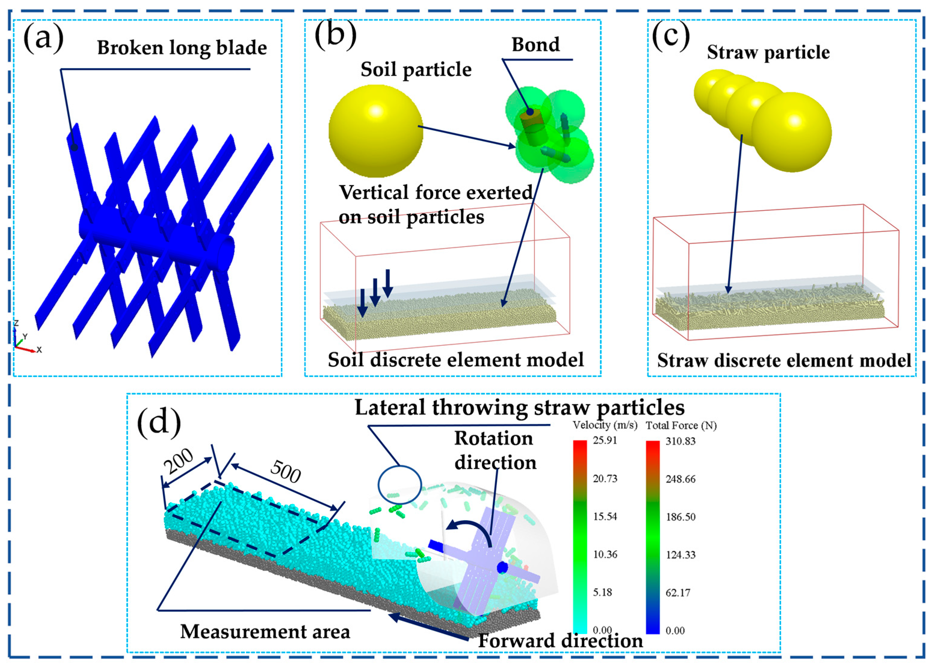
The straw crushing and spreading device was simulated using SolidWorks 2017 (Dassault Systèmes, Paris, France) at a consistent scale. However, the impact of the negative pressure blade on the device’s performance was not considered in this simulation, leading to the exclusion of the corresponding parts from the model. To enhance simulation efficiency and effectiveness, the crushing and spreading blade shaft, as well as the spreading control worm shell, were appropriately simplified. Specifically, the crushing and spreading blade shaft now comprises only the blade roller and the crushing long blade, while the spreading control worm shell retains the worm shell body and the guide plate. The discrete element simulation system model is illustrated in Figure 5.
The solid model assembly of the straw crushing and spreading device, formatted in ASM, was imported into EDEM 2018 software (Altair Engineering, Troy, MI, USA). To simulate the operating environment in the field, a virtual soil trench model measuring 4000 × 500 × 350 mm was created. Soil particles were represented by spheres with a diameter of 8 mm, and a 100 mm thick soil layer was generated using the gravity deposition method, ensuring that the virtual soil accurately reflected the characteristics of actual soil. A vertical load was applied to the top of the soil layer to achieve the measured soil density, ensuring that the virtual soil matched the actual soil parameters. To imitate straw particles, a sphere with a diameter of 20 mm and a spacing of 10 mm between spheres was utilized to create linear particles measuring 120 mm in length. The corn stover particles were replaced with 1 mm spherical particle fillers containing bond keys, according to the API’s specifications for simulating straw crushing. Additionally, a particle factory was established to generate a 120 mm thick layer of corn stover above the soil layer. The straw crushing and spreading device model was then introduced into the soil trough, which was filled with corn stover particles, to assemble the corn stover-soil-straw crushing and spreading device system model.

2.4.2. Contact Modeling and Eigenparameters

It is necessary to use an appropriate material contact model and accurately determine the intrinsic parameters to ensure the accuracy of discrete element simulation. In the spring sowing season in Heilongjiang Province, the surface soil is damp, and there is stickiness between soil particles. To accurately represent this, the Hertz–Mindlin model with bonding contact is selected as the contact model between soil particles. The Hertz–Mindlin contact model integrates Hertz’s nonlinear elastic collision theory with Mindlin’s viscous friction theory, effectively simulating the nonlinear elastic deformation and frictional interactions between particles. The adhesive Hertz–Mindlin model, which further incorporates adhesive forces, enhances the accuracy of particle interaction descriptions, particularly in cases where there is significant adhesion or agglomeration. This model has been widely applied in agricultural engineering, where such phenomena are common. This model can simulate the adhesion between soil particles, as well as the transfer of force and torque, by incorporating bonding parameters. The normal stiffness per unit area is 3.4 × 10⁸ N/m2, while the shear stiffness per unit area is 1.5 × 10⁸ N/m2. The critical normal stress is 2.1 × 10⁵ N/m2, and the critical shear stress is 6.8 × 10⁴ N/m2 [28]. The Hertz–Mindlin (no slip) contact model was employed to analyze the interactions between several materials, including corn stover and corn stover, corn stover and throw regulation worm shell, corn stover and crushed throw blade shaft, corn stover and soil, soil and throw regulation worm shell, and soil and crushed throw blade shaft [29]. The crushing and spreading blade shaft was made of 65 Mn, while the spreading and regulating worm shell was made of Q235A. The contact and intrinsic parameters may be seen in Table 2.
This study employs the Hertz–Mindlin model with inherent bonding capabilities within discrete element simulation software to develop a bonding model for straw particles. The bonding process facilitates the adhesion of particles, and when the tangential and normal forces exerted on the bond exceed specified threshold values, the bond fractures, leading to particle separation and material crushing. Consequently, the corn stover is consolidated through the bonding of small particles. The simulation will concentrate on the characteristics of the internal mechanical structure, specifically examining normal stiffness, tangential stiffness, critical normal stress, and critical tangential stress [30,31,32,33]. These four parameters, derived from existing literature, will determine the strength of the bonding between particles at a specific moment. This comprehensive approach enables the model to more accurately simulate the dynamic behavior of granular systems. Based on prior research, the average size of corn stover particles has been selected to construct a corn-shaped model. Discrete element simulation software is utilized to efficiently generate particles with a diameter of 1 mm to populate the corn stover model. These particles are produced according to a normal distribution, and 641 small particles are projected and adjusted using a formula to achieve the desired effect within the corn stover model. The XYZ positional parameters of the target particles were collected, and the API was assembled to swiftly replace the corn stover model created by the target particles. This was followed by generating the particle bonding key to shape the corn model. The Bulk Material option specifies the attribute characteristics of the desired corn stover particles and identifies which corn stover particles will be replaced and substituted.

2.4.3. Simulation Test Program

Upon investigation, it is evident that when the operating speed of the straw mulching no-tillage planter increases, the rate at which the straw crushing and spreading mechanism processes corn stover per unit of time also increases. The simulation test employed the four-factor, five-level quadratic regression orthogonal rotating center combination test method. The test factors included crushing long blade edge angle, crushing long blade edge thickness, crushing long blade weight, and crushing long blade rotational speed. The performance evaluation indexes were the straw pick-up rate, straw crushing rate, power consumption, and straw cleaning consistency between rows. A total of 30 groups were conducted, with each test repeated three times to obtain the average value. The coding of the test factor levels can be found in Table 3.
  • Crushing long blade edge angle: The blade angle is a critical parameter that influences cutting resistance and straw crushing patterns. A smaller blade angle facilitates penetration but may compromise blade strength, whereas a larger angle significantly increases cutting resistance, adversely affecting crushing efficiency and power consumption. Based on preliminary theoretical analyses and existing blade design experiences, the optimal blade angle range is selected to be between 15° and 35°.
  • Crushing long blade edge thickness: The edge thickness has a direct impact on cutting resistance and straw crushing morphology. A thinner edge reduces cutting resistance but is more susceptible to wear, while a thicker edge provides better wear resistance but increases resistance and power consumption.
  • Crushing long blade weight: The weight of the blade affects its rotational inertia and impact kinetic energy, thereby influencing pick-up capacity, crushing efficiency, and overall machine vibration. Insufficient weight results in inadequate impact force, while excessive weight leads to a significant increase in power consumption. Considering the actual blade material (65Mn) and structural strength requirements, the weight range is established at 0.3 to 0.7 kg.
  • Crushing long blade rotational speed: Rotational speed is the primary factor determining straw pick-up, crushing, and scattering performance. A speed that is too low results in incomplete straw processing, while a speed that is too high leads to a dramatic increase in power consumption and vibration. Based on the existing design and material properties of straw crushing blades, the edge thickness is set between 0.25 and 1.25 mm to evaluate its comprehensive impact on crushing quality and energy consumption. Furthermore, based on preliminary linear velocity calculations and the existing rotational speed range of the straw returning machine, the rotational speed is established at 750 to 1750 r/min, corresponding to a blade tip linear velocity of approximately 30 to 48 m/s.
The selection and measurement of performance evaluation indexes are based on the quality evaluation technical specifications of the straw returner (NY/T 1004-2006), straw crushing returner (JB/T 6678-2001), and round bale baler test method (GB/T 14290-1993) [34,35,36]. The evaluation indexes consist of straw pick-up rate, straw crushing rate, power consumption, and consistency of straw cleaning between rows.

2.4.4. Methods for Determining Performance Indicators

The straw pick-up rate: The capability to effectively collect straw, which serves as a prerequisite for ensuring the smooth execution of subsequent crushing and spreading operations. By employing the grain bin group function in the post-processing of EDEM 2018 software, one can analyze the changes in both quantity and quality of straw within the cleaning width before and after the straw removal process. The formula for calculating the straw pick-up rate is as follows:
η i = 1 N f 0 N f × 100 %
where ηi is the straw pick-up rate, %; Nf0 is the number of straws in the width of the clearing strip at the end of the simulation; Nf is the number of straws in the width of the clearing strip before the start of the simulation.
The straw crushing rate: This indicator is used to measure the crushing degree of straw by the device. This rate is calculated by statistically analyzing the quantity of straw exhibiting 60% bonding breakage in relation to the total quantity of collected straw, utilizing the EDEM 2018 post-processing function. The formula for calculating the straw crushing rate is as follows:
η j = N 0 N f N f 0 × 100 %
where ηj is the straw breakage rate, %; N0 is the 60% number of bond-breaking straw.
Power consumption: The overall power consumption is mostly attributed to the rotational torque created by the straw crushing and spreading equipment. The torque can be acquired using EDEM 2018 post-processing. The formula for determining the power consumption of the straw crushing and spreading mechanism is as follows:
p f = M f n f 9550
where pf is the power consumption, kW; Mf is the straw crushing and scattering device torque, N-m; nf is the blade roller speed, r/min.
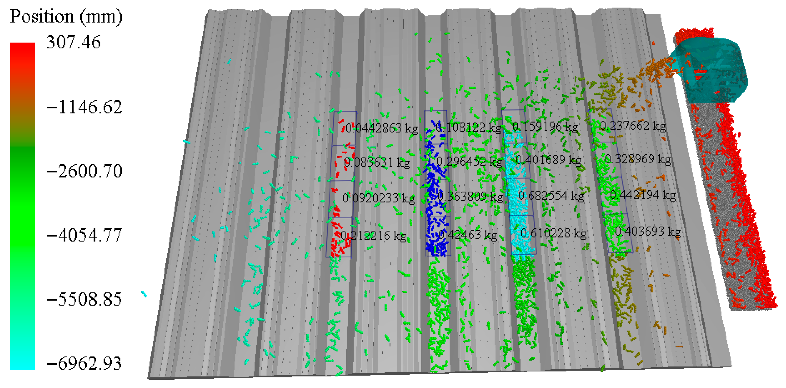
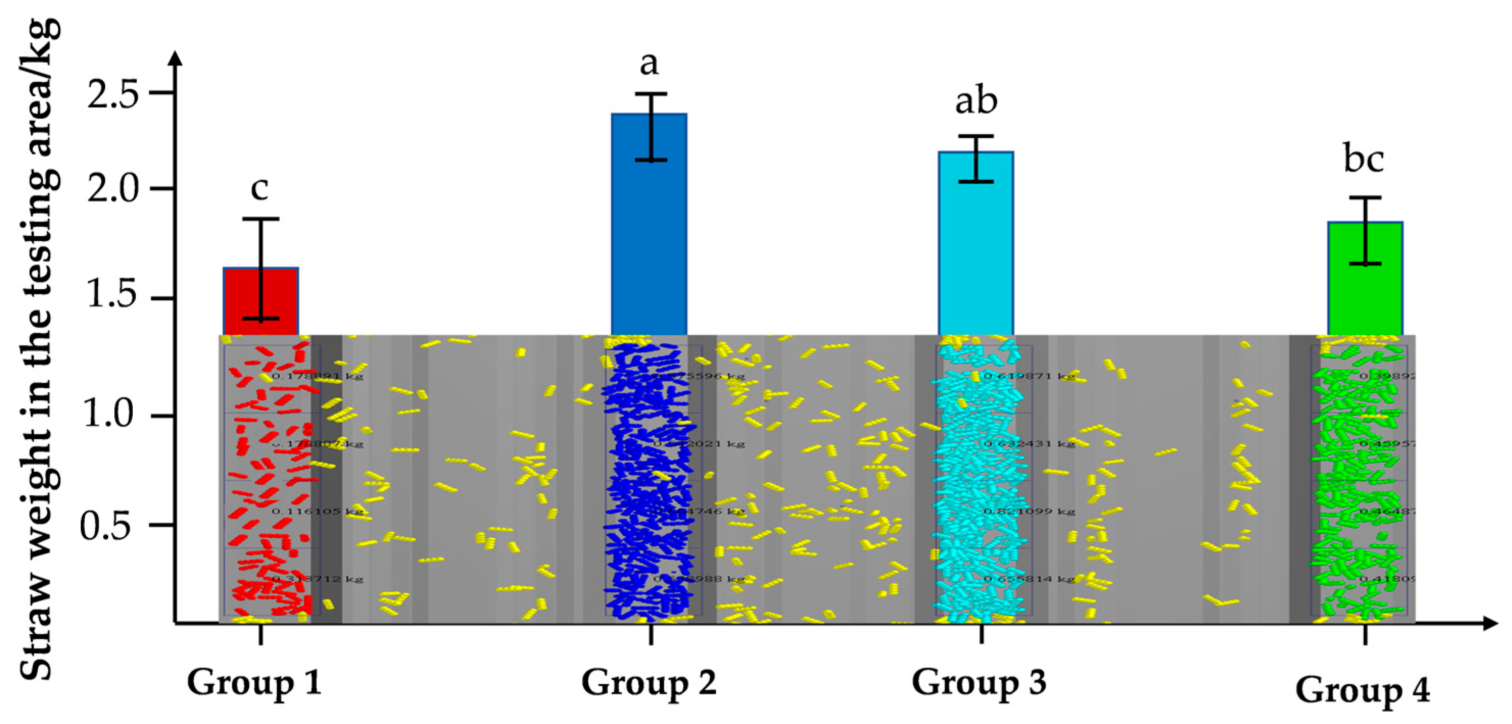
The straw cleaning consistency between rows: This indicator evaluates the uniformity of crushed straw distribution between ridges. Utilizing the Selection module in EDEM 2018 for post-processing, we established four sets of Grid Bin Group meshes (totaling 16 grids) positioned 10 mm below the ridge top plane, with each set comprising 4 grids. Each grid measures 500 × 200 mm. The weight of corn straw particles within each of the 16 grids was recorded separately, and the consistency of straw mulching between ridges under various treatments was calculated using Equation (17).
C L = 1 i = 1 4 4 M i i = 1 4 M i 2 3 i = 1 4 M i 2 M i = j = 1 4 M ij 4 ,   i = 1 , 2 , 3 , 4
where CL is the straw cleaning consistency between rows; Mi is the amount of straw cover in the ith group of rows, kg; Mij is the amount of straw cover in the ith group of rows corresponding to the jth grid of the measurement area, kg.

2.5. Field Trials

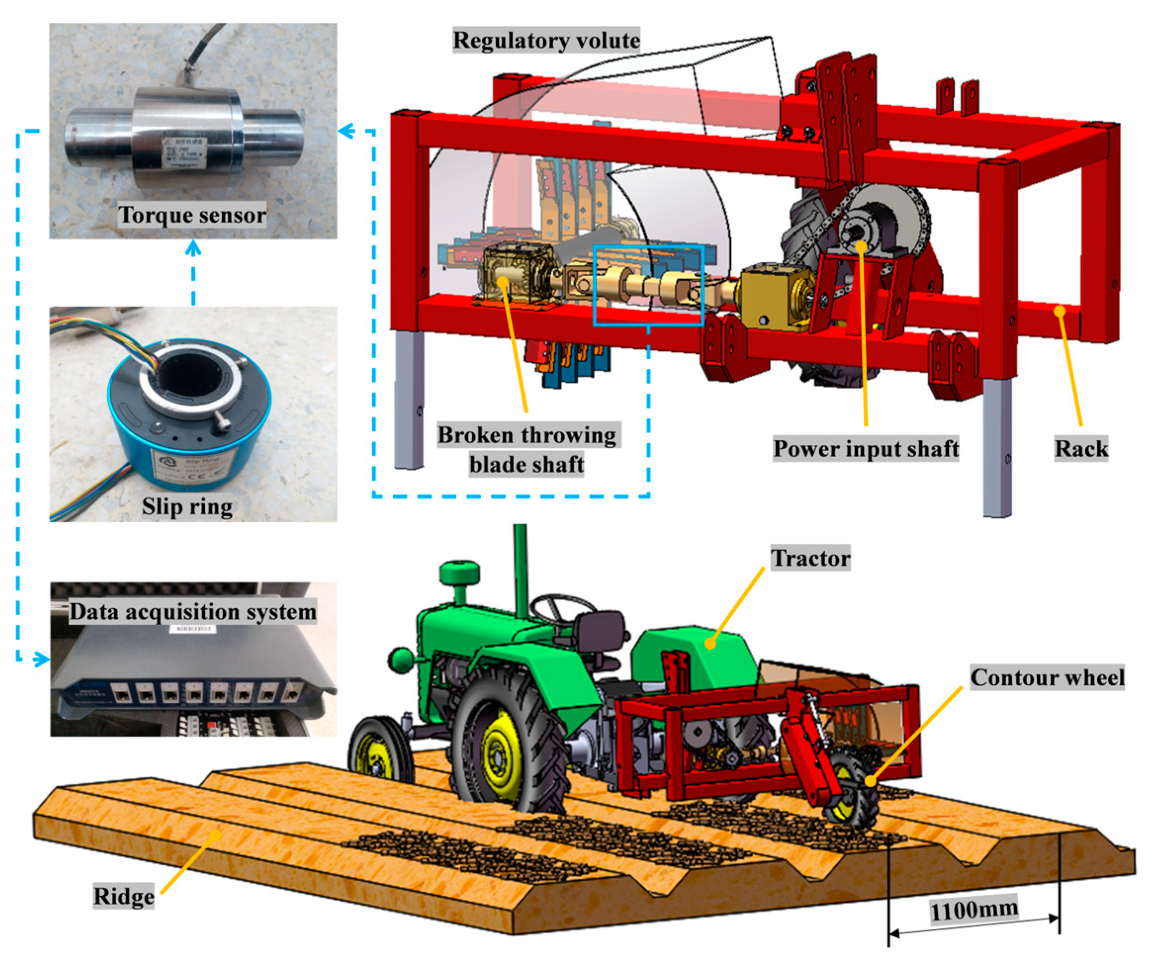
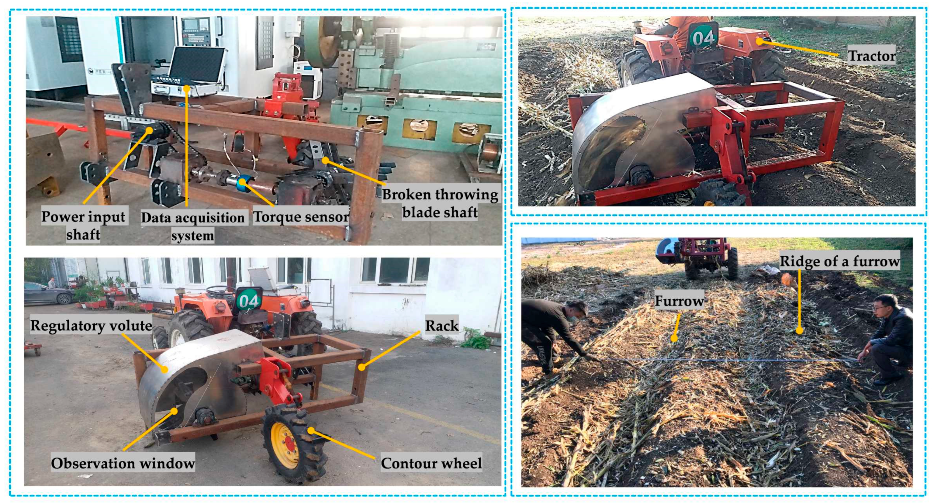
These combinations were tested in the field to validate the accuracy and rationality of the optimized parameter combinations employed in the virtual simulation test. Figure 6 illustrates the primary elements of the straw crushing and spreading test equipment, which consist of the frame, gearbox system, straw crushing and spreading device, data collector, torque sensor, profiling wheel, and laptop computer.
Experimental Conditions: The trial was conducted from October 8 to 10, 2019, at the experimental base of Northeast Agricultural University, located in Harbin City, Heilongjiang Province (Geographic coordinates: E 126°37′, N 45°44′). The test area featured typical black clay soil with an average moisture content of 31.7%. Environmental conditions reflected a typical autumn climate, with daytime temperatures ranging from 8 to 13 °C, clear skies, light winds (the average wind speed is less than 2 m/s.), and moderate humidity. To ensure the consistency and comparability of the test results, the following control measures were implemented: the field was uniformly leveled prior to the test, corn stalks were manually collected and arranged in rows, with coverage controlled at 1.95 to 2.00 kg/m2; the average length of the stalk samples was 120 mm, with a moisture content of 43.2%, all taken from the same batch and maintained at a stable condition; the test was repeated three times, with the operating speed uniformly set at 10.8 km/h.
Test instruments and equipment:454 tractor (Ningbo Benye Heavy Industry Co., Ltd., Ningbo, China), straw crushing and scattering test device, JM5938A real-time data acquisition device (Yangzhou Jingming Technology Co., Ltd., Yangzhou, China), JNNT-0 torque measurement sensor (Bengbu Sensor System Engineering Co., Ltd., Bengbu, China), PV6.08 penetrometer (Eijkelkamp, Giesbeek, The Netherlands), SU-LB soil moisture meter (Beijing Mengchuang Weiye Technology Co., Ltd., Beijing, China), LQ-T3 electronic scale (0.1 g) (Mettler-Toledo Instruments Co., Ltd., Shanghai, China), sampling frame (Custom-made), tape measure (Tajima Tool Co., Ltd., Shanghai, China), etc.
The test program involves processing and evaluating the test device based on the combination parameters identified through simulation optimization. The performance indices are measured using the performance index measurement method. The frame’s three-point suspension is connected to the hydraulic lifting and traction device of the tractor. Power output from the tractor’s power output shaft is transmitted to the straw crushing and spreading device. The transmission system is equipped with a torque measuring sensor and a collector ring, which are connected to the JM5938A real-time data collection device. This setup enables the collection of torque and rotational speed data from the straw crushing and spreading device during operation. A transparent window is installed on the lateral surface of the spreading control worm shell to facilitate observation of the motion and crushing behavior of the corn stover. Three repeated tests were conducted under optimized parameter combinations, with an operating speed of 10.8 km/h and a test distance of 200 m. An independent samples t-test was conducted using SPSS Statistics 22.0 software (IBM Corp., Armonk, NY, USA) to assess whether the two samples originated from populations with identical means.

3. Results and Discussion

3.1. Characteristic Analysis of Straw Pellet Crushing

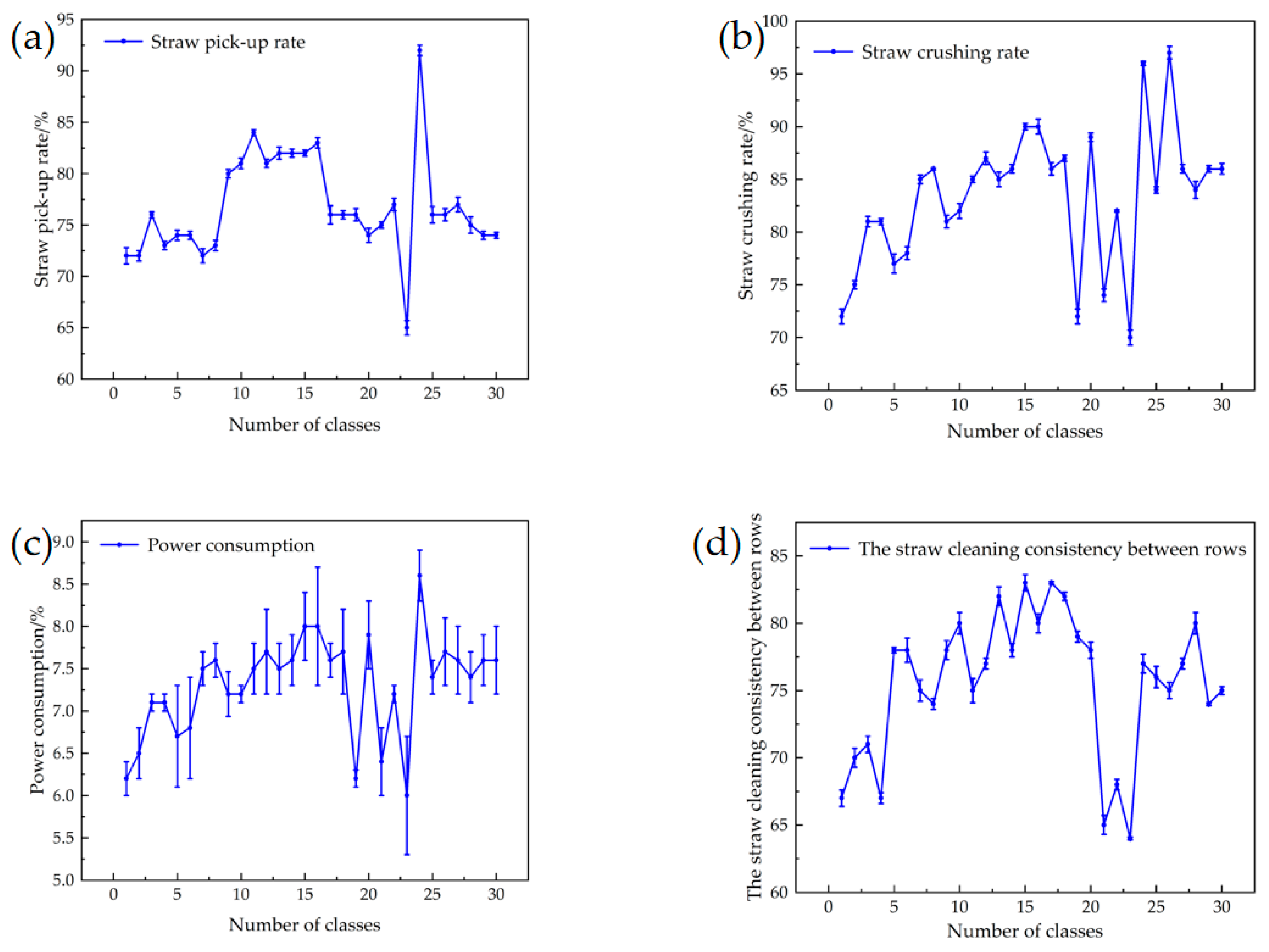
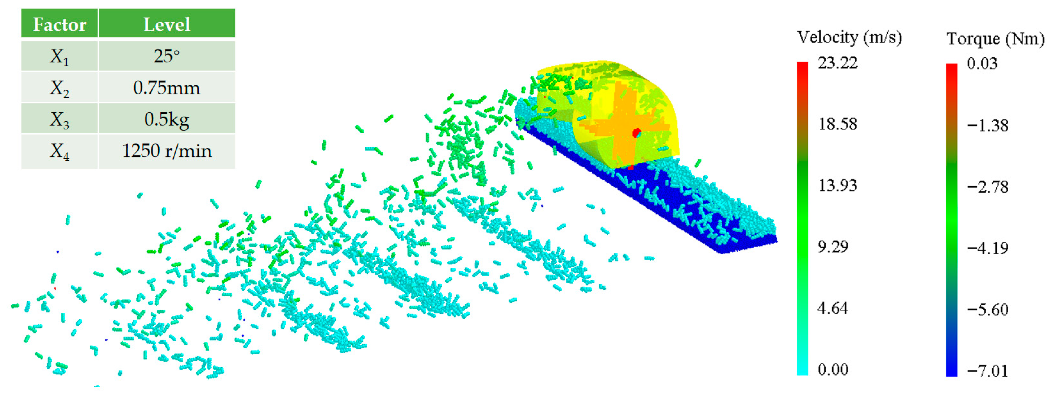
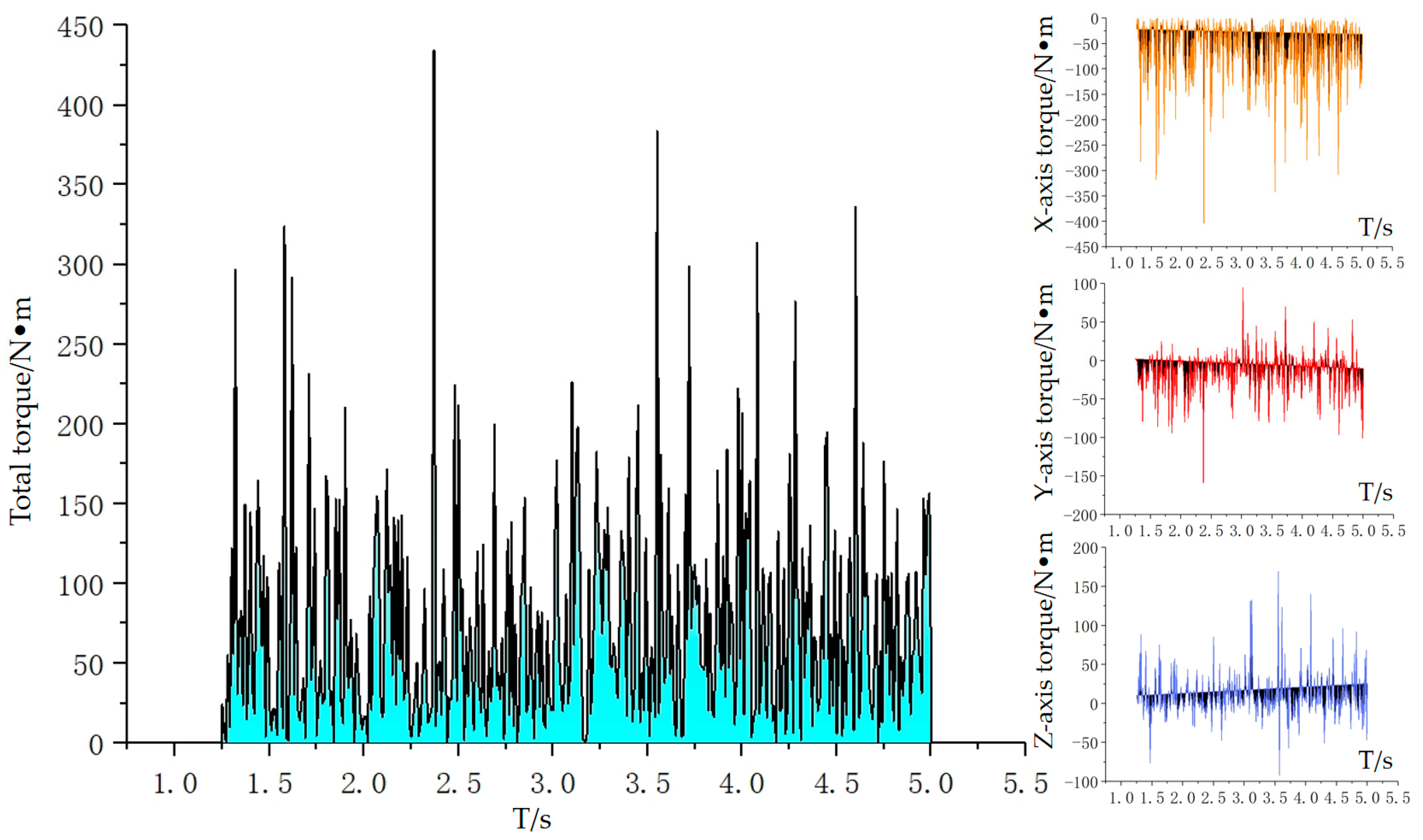
Using a four-factor, five-level quadratic regression orthogonal rotating center combination experimental design, a total of 30 test groups were conducted, with each group repeated three times. The average values of these repetitions were recorded as the final test results, as presented in Table 4 and Figure 7. When the blade angle of the crushing long blade is set to 25°, the edge thickness measures 0.75 mm. The crushing long blade weighs 0.5 kg and rotates at a speed of 1250 r/min. Discrete element simulations reveal the movement of the corn stover and the forces exerted on the axle of the stover crushing and spreading blade, as depicted in Figure 8. The pick-up rate of corn stover exceeds 70%, and the corn stover detached from the crushing and spreading blade shaft achieves a higher initial speed, facilitating subsequent stover spreading. The shaft of the corn stover crushing and spreading blade is designed with a structure comprising four groups of crushing long knives, spaced 90 mm apart, with the first two groups primarily serving the purpose of picking up during the collection process. Additionally, the first two groups of crushing long knives experience greater forces compared to the other groups. Figure 9 illustrates that the torque of the crushing and spreading blade shaft varies without a specific pattern. This variability is primarily due to the random generation of position, size, bonding, and other factors of the corn stover by the EDEM software. However, the power consumption of the crushing and spreading blade shaft can be calculated using the average torque. When all influencing factors are centered at the design’s focal point, the average torque in the x-axis direction is measured at 57.3 N·m. This value is derived from the relationship between torque, power consumption, and rotational speed. Consequently, the average power consumption of the crushing and spreading blade shaft is calculated to be 7.5 kW. This principle can also be utilized to determine the average power consumption of the crushing and spreading blade shaft for the processes of picking up, crushing, and spreading corn stover under any circumstances.
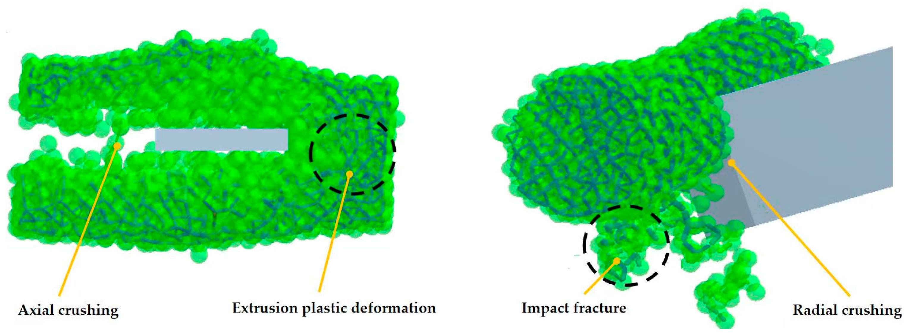
Figure 10 illustrates the process of breaking the bonds in corn stover. The straw crushing device categorizes the crushing of corn stover into three modes: axial crushing, radial crushing, and combined crushing. The primary method of crushing corn stover involves the striking and cutting action of a long blade. Due to the high toughness of corn stover, the cutting process primarily results in plastic deformation rather than an immediate breakdown of the material into loose particles. Axial crushing mainly entails cutting without causing the material to disintegrate. Conversely, radial crushing relies on striking to fragment the straw particles, which leads to some material being blown apart. Nevertheless, even after this fragmentation, the material retains some bonding structures. Radial crushing predominantly employs impact force to break the straw particles, resulting in a blow-up phenomenon; however, the material continues to maintain some bonds post-fracture. Consequently, it can be observed that the fracture process closely resembles the actual corn stover crushing process. For the bond breakage statistics, three specific corn stover particles are selected. In the computational domain, a total of 51,003 bonds are created, averaging 17,001 bonds per discrete element model of corn stover particles. During the simulation time from 0 to 0.2 s, the corn stover rapidly contacts the crushing long blade, leading to a sharp decrease in the number of bonds. From 0.2 to 1 s, the corn stover, crushing long blade, and the inner wall of the spreading control worm shell collide repeatedly, resulting in a steady decline in the number of key bond breakages. From 1.0 to 2.0 s, the corn stover separates from the crushing long blade and enters the spreading stage, culminating in the breakdown of the corn stover. During the simulated period of 1.0 to 2.0 s, the corn stover became detached from the long blade and transitioned into the spreading stage without any reduction in the number of bonds. The majority of bond breakage occurs when the corn stover enters the spreading worm shell, primarily due to the narrow spacing between the entrance of the spreading worm shell and the crushing long blade. As the corn stover enters the spreading worm shell at high speed, its velocity decreases significantly at the entrance. Meanwhile, the crushing long blade maintains a higher linear speed, resulting in a greater impulse being exerted on the corn stover. This leads to a sharp increase in the force applied by the crushing long blade, resulting in a more effective striking and cutting action. Consequently, the corn stover is crushed with greater force by the crushing long blade, thereby improving the rate of crushing. The corn stover particles undergo a series of processes from the inlet to the outlet of the straw crushing and spreading device, where they are subjected to multiple cuts and strikes by the crushing long blade. In this process, approximately 64% of the bonds between the particles are broken, indicating that the desired crushing effect has been achieved.

3.2. Characterization of the Motion of the Straw Particle Population

Assuming a crushing long blade angle of 25°, a thickness of 0.75 mm, a weight of 0.5 kg, and a rotational speed of 1250 r/min, the corn stover particles are ejected laterally to mulch the stover between the ridges, as illustrated in Figure 11. The straw crushing and spreading device is capable of ejecting corn stover laterally over a distance exceeding 6800 mm, which significantly surpasses the width of the straw treatment device (4400 mm), thereby fulfilling the spreading distance requirements. When the operational duration of the straw crushing and spreading device is set to 1.5 s, it is observed that the output and distribution of corn stover reach a consistent and smooth state, resulting in enhanced stability of the straw cleanliness between rows.
In the measured area, the distribution of corn stover among the plowed ridges was statistically analyzed. This analysis aids in understanding the consistency of straw cleaning between rows. As illustrated in Figure 12, the distribution of corn stover among the ridges exhibited variability, with a higher concentration observed in the middle and a lower concentration on the two sides. The ridges located farthest from the stover spreading device exhibited the least amount of stover. The second and third groups of ridges displayed a similar and the highest level of straw cover among all groups. No significant difference in straw coverage was found between the third and fourth groups of ridges. However, a significant difference in straw cover was noted between the second and fourth groups. Additionally, while no significant difference in straw cover was observed between the first and fourth groups, a significant difference was identified between the third and first groups.
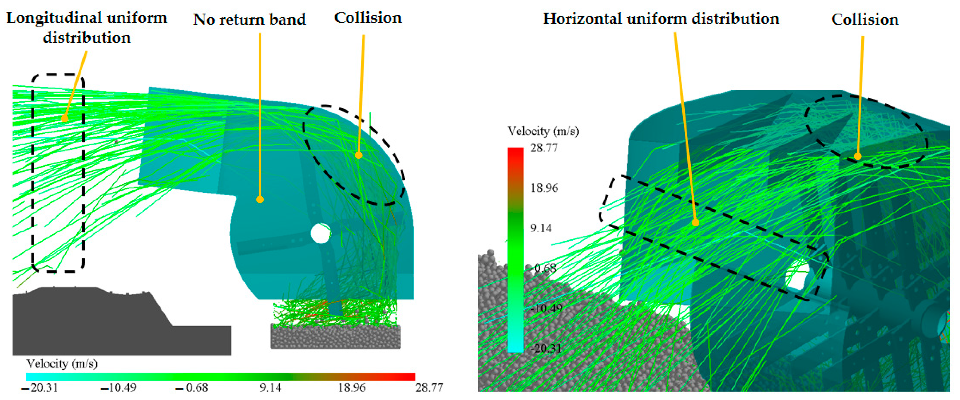
Figure 13 illustrates that the corn stover is collected within the casting control worm shell when it separates from the crushing long blade and collides with the upper surface of the shell. This collision facilitates a uniform distribution of the corn stover in both longitudinal and lateral directions, thereby creating favorable conditions for enhancing the consistency of straw cleaning between rows.
The experimental results were analyzed using Analysis of Variance (ANOVA) with Design-Expert 8.0.6.1 software (Stat-Ease, Inc., Minneapolis, MN, USA) [26]. As presented in Table 5, quadratic regression models were established to investigate the response relationships between various factors and performance indicators, followed by multi-objective parameter optimization. The significance was assessed using p-values, with all four mathematical regression models yielding p-values greater than 0.05, indicating non-significance. This finding demonstrates that the predicted values from the aforementioned regression models align closely with the measured values, with no significant lack-of-fit influencing factors identified. The models exhibit strong fitting performance, rendering them suitable for data analysis and prediction, and facilitating the exploration of the relationship between response values and various influencing factors. for the evaluation indexes of straw crushing rate, the thickness of crushing long blade edge, crushing long blade rotational speed have a highly significant effect on it (p < 0.01), the weight of crushing long blade has a significant effect on it (0.01 < p < 0.05), and the crushing long blade angle had no significant effect; for the evaluation index of power consumption, the thickness of crushing long blade edge, the weight of crushing long blade, and the rotational speed of crushing long blade have a highly significant effect on it (p < 0.01), and the blade angle of crushing long blade has no significant effect on it; for the evaluation index of the straw cleaning consistency between rows, the weight of crushing long blade and the rotational speed of crushing long blade have a highly significant effect on it (p < 0.01).
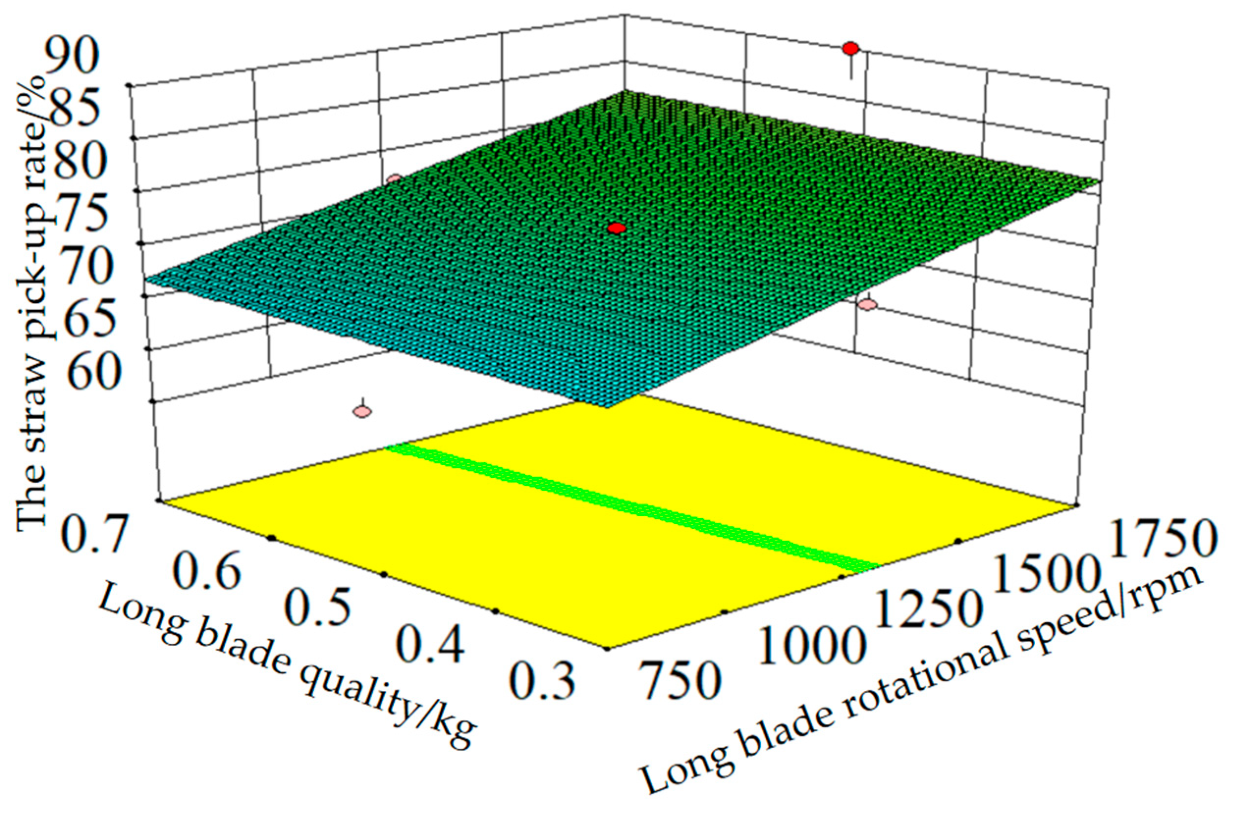
The influence of each factor on the straw pick-up rate follows the order of crushing long blade rotational speed, crushing long blade weight, crushing long blade edge thickness, and crushing long blade edge angle. The interaction between these factors has a small effect on the straw pick-up rate. Figure 14 demonstrates that when the angle and thickness of the crushing long blade edge are at the design center point, the straw pick-up rate increases as the crushing long blade speed increases. This is primarily because the higher speed of the crushing long blade results in a faster initial pick-up of corn stover, increasing the likelihood of it entering the spreading regulating worm shell and consequently increasing the straw pick-up rate. Chen et al. conducted a simulation analysis using discrete element methods to examine the performance of a picking device in a straw strip picking and crushing and deep burial device [37]. They found that the speed of straw picking and scattering was directly related to the rotational speed of the picking device. In a separate study, Yuan et al. analyzed the performance of a straw-throwing fan in a straw-crushing and centralized full-volume deep burial machine [38]. They established that there is a positive correlation between the height and speed of straw throwing and the rotational speed of the straw throwing mechanism. Speed is directly proportional. The study in this paper implemented high-speed operating conditions, in contrast to the lower operating speeds (less than 3 hm/h) of the previous research devices. However, the correlation between the straw pick-up rate and the rotational speed of the crushing long knives remains consistent with the findings of the above studies.
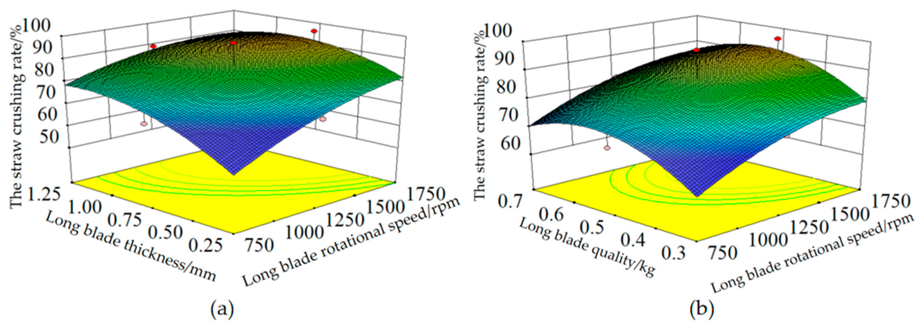
The factors that have the greatest influence on the straw crushing rate, in descending order, are the rotational speed of the crushing long blade, the thickness of the crushing long blade edge, the weight of the crushing long blade, and the angle of the crushing long blade edge. The interaction between these factors does not have a significant effect on the straw pick-up rate. The impact of the thickness and rotational speed of the crushing long blade on the straw crushing rate is illustrated in Figure 15a when both the crushing long blade edge angle and weight are positioned at the design center point. It is observed that when the rotational speed of the crushing long blade is below 1500 r/min, the straw crushing rate increases as the thickness of the crushing long blade edge increases. This is because at lower rotational speeds, the crushing long blade primarily crushes the corn stover through impact, resulting in a less effective cutting action. Consequently, the crushing long blade does not significantly affect the straw pick-up rate. When the rotational speed of the crushing long blade exceeds 1500 r/min, the straw crushing rate demonstrates a pattern of initially increasing and then decreasing as the thickness of the crushing long blade increases. However, this trend is not particularly pronounced. This phenomenon can be attributed to the fact that at higher rotational speeds, the crushing of corn stover primarily relies on a combination of striking and cutting, with the cutting effect being more prominent. When the rotating speed of the crushing blade is increased, the corn stover is crushed by a combination of hitting and cutting, resulting in a noticeable cutting effect. The straw crushing rate is directly proportional to the speed of the cutting edge of the crushing long blade when its thickness is fixed. This is primarily because higher speeds result in greater kinetic energy, leading to improved crushing efficiency. In their study, Liu et al. performed a theoretical analysis of the working performance of the picking, crushing, and spreading device in the design and experimental study of the opposite-speed roller corn stover crushing and returning device [14]. They found that increasing the rotational speed of the device can enhance the quality of straw crushing and the crushing rate. These findings align with the results obtained in this research. Nevertheless, after the device achieves a speed of 1600 revolutions per minute, the rate at which the straw is crushed tends to decline. This phenomenon could potentially be attributed to the structural design of the blade edge. Figure 15b illustrates the impact of the weight and rotational speed of the crushing long blade on the straw crushing rate. When the blade angle and edge thickness of the crushing long blade are centered in the design, it is observed that the straw crushing rate increases as the weight of the crushing long blade increases. This is primarily due to the impulse theorem, which states that a greater weight of the crushing long blade results in a stronger striking force applied to the corn stover within the same time frame. Consequently, this leads to improved crushing outcomes and a higher straw crushing rate. This enhances the impact, resulting in a higher straw crushing rate.
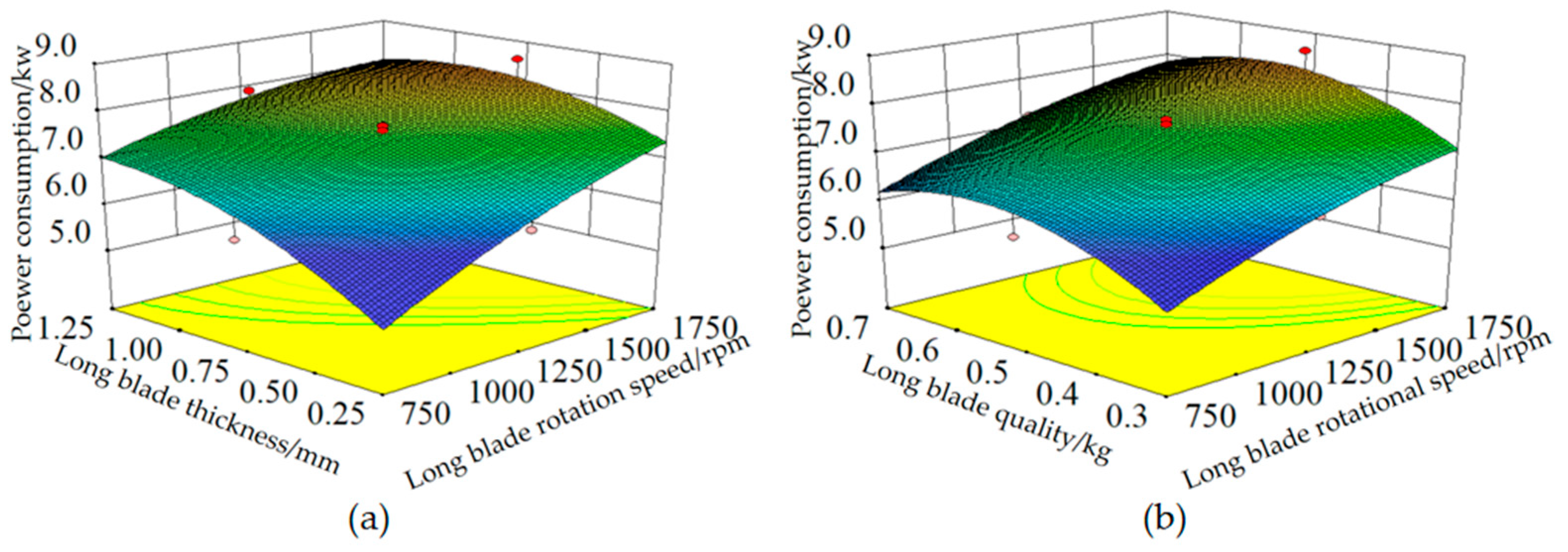
The primary–secondary factors affecting power consumption are the rotational speed of the crushing long blade, the thickness of its edge, its weight, and its edge angle. The interaction between these factors does not have a significant impact on the straw pick-up rate. Figure 16a illustrates the impact of the thickness and rotational speed of the crushing long blade on power consumption when they are positioned at the design center point. When the rotational speed of the crushing long blade is held constant, increasing the thickness of the blade edge leads to higher power consumption. This is primarily because the increased thickness of the blade edge results in greater resistance during the crushing of corn stover, thus requiring more power. The authors, M.A. Matin et al. observed that increasing the thickness of the cutting edge of the tool resulted in irregularities in the soil cutting plane [39]. This irregularity is a sign of higher power consumption, which aligns with the findings of the current research paper. This is analogous to the straw cutting described in the paper, and the findings are congruent. When the thickness of the cutting edge of the crushing long blade is fixed, the power consumption rises in tandem with the rotational speed of the crushing long blade. This is primarily attributed to the augmented kinetic energy resulting from the increased rotational speed, which consequently leads to an increase in power consumption. In their study, Xia et al. examined the power consumption of the blade roller in the design and experimental analysis of a six-head spiral straw return tiller using response surface testing [40]. They found that the speed of the blade roller is directly related to the power consumption, which aligns with the findings of this paper. When the angle of the cutting edge and the thickness of the cutting edge of the crushing blade are at the design center point, the impact of the weight and speed of the crushing blade on power consumption is depicted in Figure 16b. When the rotational speed of the crushing long blade is constant, power consumption increases with its weight. The increase in weight of the crushing long blade primarily increase its rotational inertia, which in turn leads to higher power consumption.
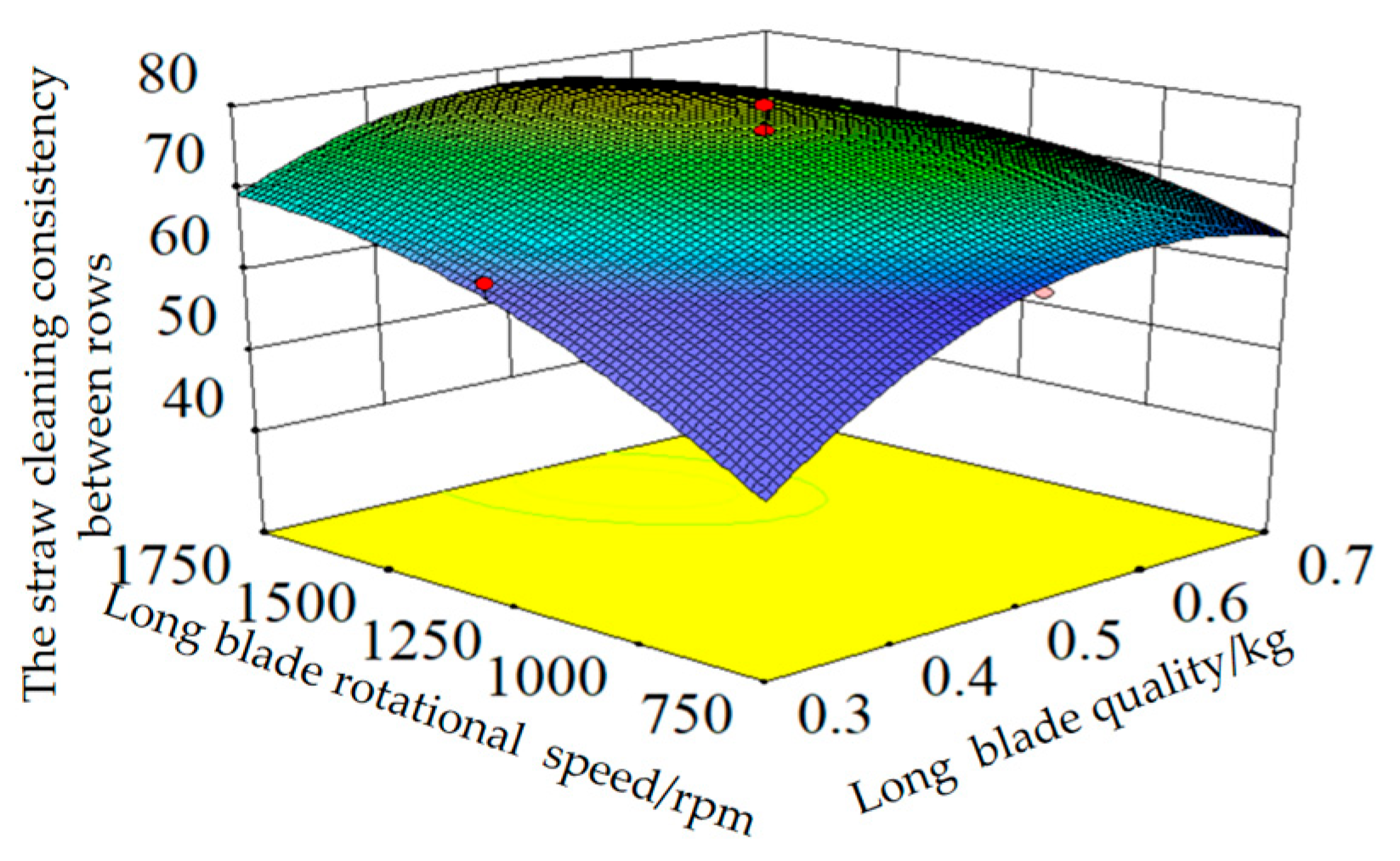
The primary–secondary relationship of factors affecting the straw cleaning consistency is as follows: the rotational speed of the crushing long blade, weight of the crushing long blade, edge thickness, and its edge angle. The interaction effects of these factors show no significant influence on the consistency of inter-row straw mulching. The interaction of each factor did not have a significant effect on the straw cleaning consistency between rows. When the blade angle and thickness of the crushing long blade are positioned at the center of the design, the impact of the blade’s weight and speed on straw cleaning consistency between rows is illustrated in Figure 17. The consistency improves with the weight of the crushing long blade but decreases when the rotational speed exceeds a certain value. This is mainly due to the increase in weight of the crushing long blade, which leads to an increase in inertia. As a result, the blade’s energy output rises, the kinetic energy obtained by the straw increases, and the spreading speed also increases. Theoretical analysis shows that an increase in the initial straw spreading speed increases the spreading distance, thereby enhancing the straw cleaning consistency between rows. However, excessively high spreading speed can reduce the number of straw pieces close to the machine, resulting in a decrease in straw cleaning consistency between rows. When the weight of the crushing long blade is constant, the straw cleaning efficiency between ridges increases with the speed of the crushing long blade. This efficiency shows a trend of initially increasing and then decreasing, with the same underlying reason as mentioned above.
The constraint for the crushing long blade were as follows: a blade angle of 15°~35°, a blade thickness of 0.25~1.25 mm, a weight of 0.3~0.7 kg, and a rotational speed of 750~1750 r/min. The optimization process aims to achieve the highest straw pick-up rate and straw-crushing rate while minimizing power consumption. The objective function and constraints are as follows:
max Y 1 ,   Y 2 ,   Y 4 ,   min Y 3 s . t . 15 ° X 1 35 ° 0.25   mm X 2 1.25   mm 0.3   kg X 3 0.7   kg 750   r / min X 3 1750   r / min
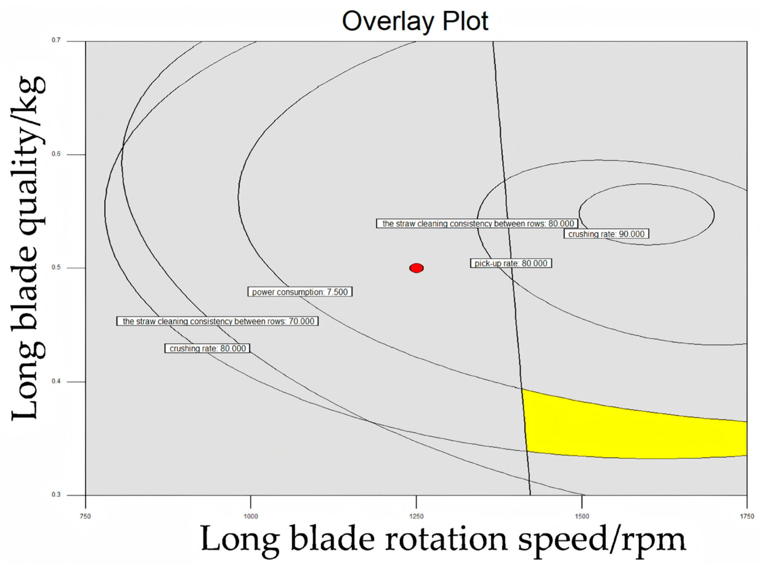
To minimize the overall weight and vibration of the machine, lower rotational speeds and reduced mass for the crushing long blade are preferable. The Design-Expert 8.0.6.1 software was utilized to identify a multi-objective optimization solution. The optimization results are presented in Figure 18. The optimal parameter combinations for the crushing long blade include an edge angle of 25°, an edge thickness of 1.25 mm, a weight ranging from 0.35 to 0.41 kg, and a rotational speed of 1400–1750 r/min. The straw pick-up rate exceeds 80%, the straw crushing rate is also greater than 80%, power consumption is below 7.5 kilowatts, and the consistency of straw cleaning between rows is above 70%.
To validate the accuracy of the optimized parameter combination results and simplify the subsequent processing of the field test prototype, a long blade model for crushing and spreading was created using SolidWorks software. This model featured a blade angle of 25°, a blade thickness of 1.25 mm, and a weight of 0.35 kg. It was subsequently imported into EDEM software for verification tests. The rotational speed was set at 1500 r/min, and a total of three tests were conducted to obtain the average values. The mean values from the three tests indicated an 83% straw pick-up rate, an 84% straw crushing rate, a power consumption of 6.8 kW, and a 75% consistency in straw cleaning between rows. These results confirm the reliability of the optimized combination derived from the discrete element method.

3.3. Field Validation Trial

Through theoretical analysis, the key structural and operational parameters affecting the straw crushing and scattering device were identified. Virtual simulation, combined with orthogonal experiments, was then employed to determine the optimal parameter combination for the device’s performance. To verify the correctness of the obtained optimal parameter combination, field tests were conducted using the device with the optimized parameters derived from the simulation experiments. Specifically, a straw crushing and scattering device was manufactured featuring a long crushing blade angle of 25°, a blade edge thickness of 1.25 mm, and a long crushing blade weight of 0.35 kg. The tests were carried out under conditions where the rotational speed of the long crushing blade was set to 1500 r/min and the operating speed was 10.8 km/h. The amount of corn straw within the working width was estimated, and straw within that width was manually collected. Each test distance was 200 m, repeated three times to obtain an average value. The test results are as follows: a straw pick-up rate of 87.2%, a straw crushing rate of 81.5%, power consumption of 7.7 kW, and a straw cleaning consistency of 79.3%. Meanwhile, the maximum lateral throwing distance reached 6300 mm, meeting the actual throwing operation requirements. The test process and results are illustrated in Figure 19.
The design, optimization, and validation of this device were specifically tailored for cold regions of Heilongjiang Province, corn-soybean rotation systems, black clay soil types, and high straw residue conditions. Therefore, its performance parameters and conclusions may not be directly applicable to regions with significantly different climates (e.g., warm or arid zones), dissimilar soil textures (e.g., sandy soils), divergent crop rotation patterns, or areas with low straw residue. Field variability remains uncontrollable: Despite meticulous planning, field trials are subject to unpredictable environmental factors. Certain variables—such as initial soil moisture differences, temperature fluctuations, and transient meteorological conditions during testing (e.g., wind speed and direction)—introduce variability that cannot be entirely eliminated.

4. Conclusions

This study addresses critical issues such as slow ground temperature recovery, delayed sowing periods, and low crop yields resulting from straw mulching after the use of no-till planters in the cold regions of Heilongjiang Province. It innovatively designs a straw crushing and scattering device integrated into the planter.
(1)
The core working components of the straw crushing and scattering device were designed, with the rotary diameter of the crushing blades established at 700 mm. Through theoretical analysis and mechanical modeling of the straw pick-up, crushing, and scattering processes, key parameters affecting the device’s performance were identified, including blade angle, edge thickness, weight, and rotational speed of the crushing blades.
(2)
A straw–soil–machine simulation model was established using the Discrete Element Method (DEM), and virtual simulation experiments, and optimization of key parameters were conducted by employing the Response Surface Methodology (RSM). Performance evaluation indicators, such as straw pick-up rate, crushing rate, power consumption, and inter-row straw coverage consistency, were utilized to derive the optimal parameter combination: a crushing long blade edge angle of 25°, a crushing long blade edge thickness of 1.25 mm, a crushing long blade weight of 0.35–0.41 kg, and a crushing long blade rotational speed of 1400–1750 r/min.
(3)
A prototype was manufactured based on the optimization results, followed by field validation tests. The results demonstrate that under the optimal parameter combination, the straw pick-up rate exceeds 87%, the straw crushing rate surpasses 81%, power consumption remains below 7.7 kW, the straw cleaning consistency approaches 80%, and the maximum lateral throwing distance reaches 6300 mm. These outcomes not only satisfy practical operational requirements but also validate the reliability of the simulation optimization results.

Author Contributions

Conceptualization, S.H., H.Z. and Y.S.; Methodology, S.H., H.Z., Y.S. and W.J.; Software, H.Z., B.J. and H.H.; Validation, N.S., W.J. and H.H.; Investigation, S.H., H.Z. and N.S.; Resources, B.J. and H.H.; Data Curation, S.H., H.Z. and Y.S.; Writing—Original Draft Preparation, S.H., H.Z. and Y.S.; Writing—Review and Editing, S.H., H.Z., Y.S. and B.J.; Supervision, N.S., C.Z., and W.J. Project Administration, W.J. and C.Z.; Funding Acquisition, W.J. and C.Z. All authors have read and agreed to the published version of the manuscript.

Funding

This work was supported by the Modern Agricultural Industrial Technology System [grant number CARS-04]. The authors express their thanks for the generous financial assistance they were provided.

Institutional Review Board Statement

Not applicable.

Informed Consent Statement

Not applicable.

Data Availability Statement

The original contributions presented in this study are included in the article. Further inquiries can be directed to the corresponding author.

Acknowledgments

The authors would like to acknowledge the College of Engineering at Northeast Agricultural University.

Conflicts of Interest

The authors declare no conflicts of interest.

References

  1. Kassam, A.; Friedrich, T.; Derpsch, R. Global spread of conservation agriculture. Int. J. Environ. Stud. 2019, 76, 29–51. [Google Scholar] [CrossRef]
  2. Wang, C.L.; Liu, C.; Lin, D.H.; Liu, Z.J.; Liu, L.J.; Tang, H. Research progress of protective utilization and maintenance technology and machine in northeast black land of China. J. Agric. Mach. 2025, 56, 1–21. [Google Scholar]
  3. Huang, B.; Gao, J.; Zhang, W.; Gan, C.; Bao, X.; Xu, M.; Wu, L. Impacts of conservation tillage on soil organic carbon and crop yield in black soil region of Northeast China: Integrated regulation by climate, management and soil properties. J. Agric. Food Res. 2025, 24, 102388. [Google Scholar] [CrossRef]
  4. Li, Y.; Guo, L.; Feng, Y.; Li, C. Long-term conservation tillage enhances soil organic carbon accumulation in rice-wheat rotation systems by improving aggregate stability and reducing carbon flow from macroaggregates to microaggregates. J. Environ. Manag. 2025, 395, 127838. [Google Scholar] [CrossRef]
  5. Guo, M.; Li, J.; Li, J.; Qi, J.; Zhang, X. Changes of soil structure and function after 16-year conservation tillage in black soil. Trans. Chin. Soc. Agric. Eng. (Trans. CSAE) 2021, 37, 108–118. [Google Scholar]
  6. Hou, S.; Wang, X.; Ji, Z.; Chen, H.; Zhou, C. Experiments on the Influence of Corn Straw Morphological Combinations on Timely No-Tillage Sowing Soil Temperature and Moisture in Cold Regions. Agriculture 2022, 12, 1425. [Google Scholar] [CrossRef]
  7. Zhu, Y.; LI, J.; Zhang, C.; Zhang, X. Effects of long-term conservation tillage on black soil organic carbon components in sloping farmland. Trans. Chin. Soc. Agric. Eng. (Trans. CSAE) 2023, 39, 103–111. [Google Scholar]
  8. Wang, K.; Fu, Q.; Zhang, Z.; Jiang, X.; Hao, Z. Effects of straw mulching mode and tillage methods on soil environment of root zone in northeast black soil. Trans. Chin. Soc. Agric. Mach. 2016, 47, 131–137. [Google Scholar]
  9. Domokos, Z.; Șimon, A.; Chețan, F.; Ceclan, O.A.; Filip, E.; Călugăr, R.E.; Vâtcă, S.D.; Duda, M.M. The influence of sowing date on the primary yield components of maize. Agronomy 2024, 14, 2120. [Google Scholar] [CrossRef]
  10. Dutta, R.; Panda, D.J. Influence of dates of sowing and planting geometry on yield, nutrient uptake and economics of baby corn. Int. J. Environ. Clim. Change 2022, 12, 25–33. [Google Scholar] [CrossRef]
  11. Shi, J.; Wang, S.; Li, S.; Tian, X. Increasing soil organic carbon sequestration and yield stability by no-tillage and straw-returning in wheat–maize rotation. Agron. J. 2022, 114, 1534–1545. [Google Scholar] [CrossRef]
  12. Sun, J.; Yang, L.; Zhang, D.; Hu, J.; Cui, T.; He, X.; Zhao, H. Development of a prediction model to determine optimal sowing depth to improve maize seedling performance. Biosyst. Eng. 2023, 234, 206–222. [Google Scholar] [CrossRef]
  13. Kang, Y.; Liao, Q.; Lin, J.; Han, J.; Wan, X.; Zhang, Q. Development of the rapeseed direct seeding machine with stubble covering based on combined harvesting machine platform. Trans. Chin. Soc. Agric. Eng. (Trans. CSAE) 2024, 40, 15–25. [Google Scholar]
  14. Zhang, X.R.; Ni, S.L.; Liu, J.X.; Hu, X.H.; Zhang, Z.F.; Fu, S.H. Design and test of bionic blade for banana straw crushing and throwing returning machine. J. Agric. Mach. 2024, 55, 128–140. [Google Scholar]
  15. Qin, K.; Cao, C.; Liao, Y.; Wang, C.; Fang, L.; Ge, J. Design and optimization of crushing and throwing device for straw returning to field and fertilizing hill-seeding machine. Trans. Chin. Soc. Agric. Eng. (Trans. CSAE) 2020, 36, 1–10. [Google Scholar]
  16. Wang, Q.; Liu, Z.; He, J.; Li, H.; Li, W.; He, J.; Yan, X. Design and experiment of chopping-type maize straw returning machine. Trans. Chin. Soc. Agric. Eng. (Trans. CSAE) 2018, 34, 10–17. [Google Scholar]
  17. Liu, P.; He, J.; Li, Y.; Li, H.; Wang, Q.; Lu, C.; Zhang, Z.; Li, S. Design and experiment of double rollers maize stalk chopping device with different rotation speeds. Trans. Chin. Soc. Agric. Eng. (Trans. CSAE) 2020, 36, 69–79. [Google Scholar]
  18. Jia, H.; Jiang, X.; Yuan, H.; Zhuang, J.; Zhao, J.; Guo, M. Stalk cutting mechanism of no-tillage planter for wide/narrow row farming mode. Int. J. Agric. Biol. Eng. 2017, 10, 26–35. [Google Scholar]
  19. Zheng, Z.; He, J.; Li, H.; Diao, P.; Wang, Q.; Zhang, X. Design and experiment of straw-chopping device with chopping and fixed knife supported slide cutting. Trans. Chin. Soc. Agric. Mach. 2016, 47, 108–116. [Google Scholar]
  20. Liu, P.; He, J.; Zhang, Z.Q.; Lu, C.Y.; Zhang, Z.G.; Lin, H. Kinematic characteristic analysis and field test of chopped stalk in straw retention machine based on cfd-dem coupling simulation method. Trans. Chin. Soc. Agric. Mach. 2020, 51, 244–253. [Google Scholar]
  21. Chen, H.; Zou, Z.; Wang, X.; Shi, N.; Han, G.; Hou, S. Design and experiment of straw proportional recovery device for clearing and covering straw of no-tillage planter. Trans. Chin. Soc. Agric. Mach. 2022, 53, 120–129. [Google Scholar]
  22. Galili, N.; Shteingauz, G. Wide-swath vertical spreader for granular material. Trans. ASAE 1982, 25, 1195–1203. [Google Scholar] [CrossRef]
  23. Cool, S.; Pieters, J.; Mertens, K.C.; Hijazi, B.; Vangeyte, J. A simulation of the influence of spinning on the ballistic flight of spherical fertiliser grains. Comput. Electron. Agric. 2014, 105, 121–131. [Google Scholar] [CrossRef]
  24. Olieslagers, R.; Ramon, H.; De Baerdemaeker, J. Calculation of fertilizer distribution patterns from a spinning disc spreader by means of a simulation model. J. Agric. Eng. Res. 1996, 63, 137–152. [Google Scholar] [CrossRef]
  25. Yi, W.; Zhou, Q.; Lu, Z.Y.; Ma, Z.J.; Zhou, H.X. Research on the influence of fluid resistance and ejection height on the motion law of projectiles. Chin. Phys. Bull. 2024, 39, 27–30, 34. (In Chinese) [Google Scholar]
  26. Zhang, X.M.; Chen, G.H. Analysis methods of projection velocity and flight trajectory of explosion fragments. Huanan Ligong Daxue Xuebao J. South China Univ. Technol. (Nat. Sci.) 2009, 37, 106–110. [Google Scholar]
  27. Bi, J.S.; Lu, C.Y.; Li, H.W.; Zhai, C.K. Design and experiment of anti-blocking device passive sawtooth disc based on optimal dynamic sliding cutting. Trans. Chin. Soc. Agric. Mach. 2025, 56, 118–128. (In Chinese) [Google Scholar]
  28. Zhao, S.; Gao, L.; Yuan, Y.; Hou, L.; Zhang, X.; Yang, Y. Maize straw motion law in subsoiling operation using discrete element method. Trans. Chin. Soc. Agric. Eng. (Trans. CSAE) 2021, 37, 53–62. [Google Scholar]
  29. Mudarisov, S.; Gabitov, I.; Lobachevsky, Y.; Farkhutdinov, I.; Kravchenko, L. Systematic Evaluation and Experimental Validation of Discrete Element Method Contact Models for Soil Tillage Simulation. AgriEngineering 2025, 7, 256. [Google Scholar] [CrossRef]
  30. Yuan, Q.; Xu, L.; Ma, S.; Niu, C.; Wang, S.; Yuan, X. Design and test of sawtooth fertilizer block crushing blade of organic fertilizer deep applicator. Trans. Chin. Soc. Agric. Eng. 2020, 36, 44–51. [Google Scholar]
  31. Wang, D.; Wang, M.; Li, L. Mechanism analysis and parameter optimization of hammer mill for corn stalk. Nongye Jixie Xuebao/Trans. Chin. Soc. Agric. Mach. 2017, 48, 165–171. [Google Scholar] [CrossRef]
  32. Liao, Y.; Wang, Z.; Liao, Q.; Liang, F.; Liu, J. Calibration of discrete element parameters of fodder rape crop stem at flowering stage. In Proceedings of the 2020 ASABE Annual International Virtual Meeting, St. Joseph, MI, USA, 13–15 July 2020; p. 1. [Google Scholar]
  33. Chen, Z.; Liu, Z.; Guan, W.; Guo, J.; Xue, D. Maize grain modelling for the dem simulation of sowing process. Trans. Chin. Soc. Agric. Eng. (Trans. CSAE) 2024, 40, 14–22. [Google Scholar]
  34. NY/T 1004-2006; Technical Specification for Quality Evaluation of Straw Returning Machine. Ministry of Agriculture of China: Beijing, China, 2006.
  35. JB/T 6678-2001; Straw Crushing and Returning Machine. Ministry of Industry and Information Technology of China: Beijing, China, 2001.
  36. GB/T 14290-1993; Test Methods for Round Balers. Hohhot Animal Husbandry Machinery Research Institute, Ministry of Machinery and Electronics Industry: Beijing, China, 1993.
  37. Chen, G.; Lu, C.; He, J.; Wang, C.; Wang, X.; Wang, Q. Design and experiment of straw pickup-crushed and deep buried device under strip-tillage. Trans. Chin. Soc. Agric. Mach. 2021, 52, 16–27. [Google Scholar]
  38. Yuan, X.M.; Li, X.H.; Jiao, H.T.; Zhou, S.L.; Zhang, J.J.; Wu, H.Y. Design and experiment of straw chopping centralized full depthand returning machine. Trans. Chin. Soc. Agric. Mach. 2023, 54, 27–35. (In Chinese) [Google Scholar]
  39. Matin, M.A.; Desbiolles, J.M.A.; Fielke, J.M. Strip-tillage using rotating straight blades: Effect of cutting edge geometry on furrow parameters. Soil Tillage Res. 2016, 155, 271–279. [Google Scholar] [CrossRef]
  40. Zhang, C.; Xia, J.; Zhang, J.; Zhou, H.; Zhu, Y.; Wang, J. Design and experiment of knife roller for six-head spiral straw returning cultivator. Trans. Chin. Soc. Agric. Mach. 2019, 50, 25–34. [Google Scholar]
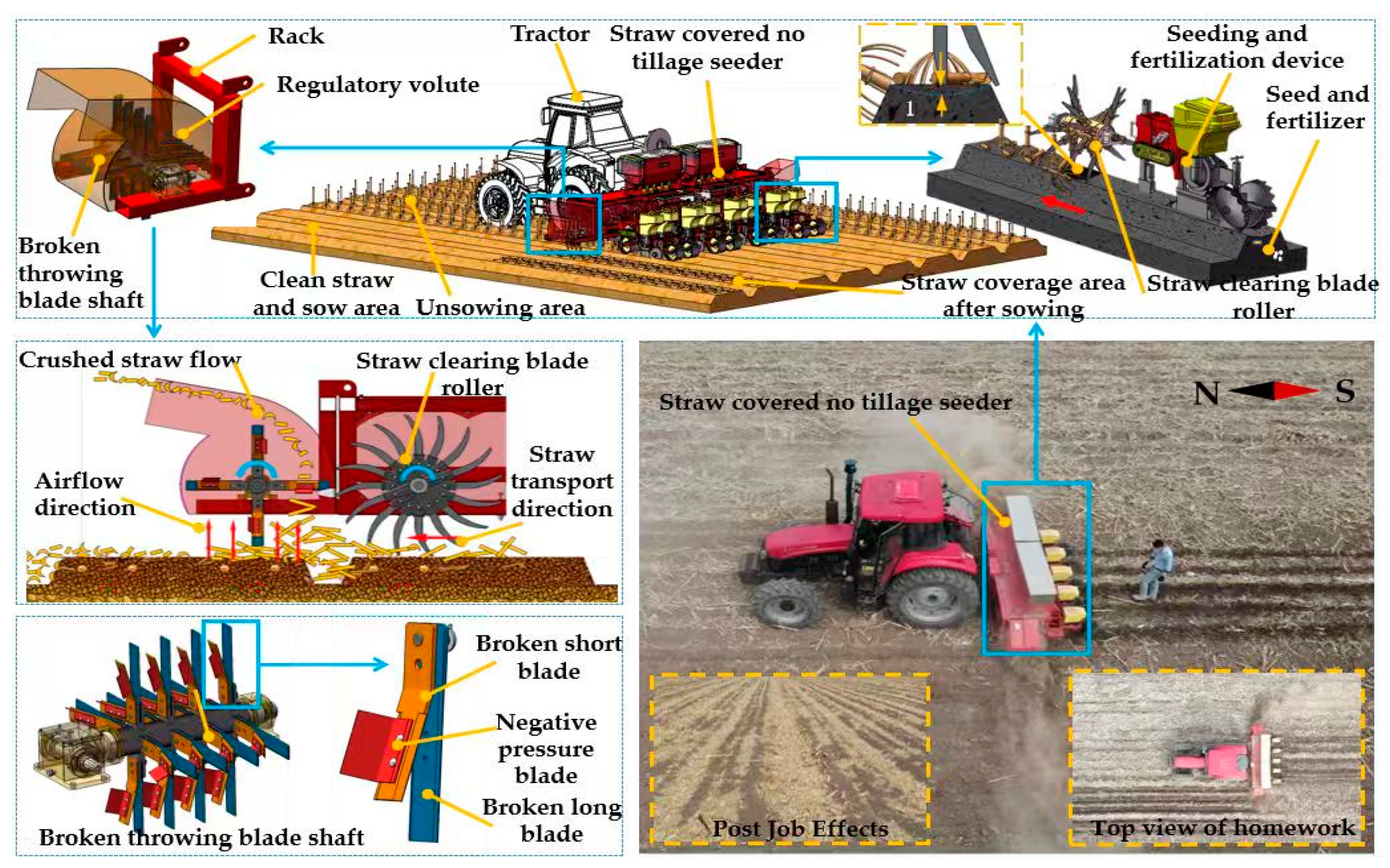
Figure 1. Structure of straw-crushing and throwing device and its working principle.
Agriculture 15 02404 g001
Figure 2. Straw picking process force analysis.
Agriculture 15 02404 g002
Figure 3. Straw crushing force analysis.
Agriculture 15 02404 g003
Figure 4. Corn stover spreading process.
Agriculture 15 02404 g004
Figure 5. Discrete element simulation system model: (a) broken long blade model; (b) soil particle model; (c) straw particle model; (d) workflow diagram.
Agriculture 15 02404 g005
Figure 6. Test instrumentation and device connections.
Agriculture 15 02404 g006
Figure 7. Test results: (a) pick-up rate results; (b) crushing rate results; (c) power consumption results; (d) straw cleaning consistency results.
Agriculture 15 02404 g007
Figure 8. Discrete element simulation process and results.
Agriculture 15 02404 g008
Figure 9. Torque change rule with time.
Agriculture 15 02404 g009
Figure 10. Breakage process of bonding bonds of corn stover particles.
Agriculture 15 02404 g010
Figure 11. Effect of corn stover spreading distance and the straw cleaning consistency between rows.
Agriculture 15 02404 g011
Figure 12. Distribution of maize stover mass in the measurement area.
Agriculture 15 02404 g012
Figure 13. Cloud map of corn stover movement trajectory.
Agriculture 15 02404 g013
Figure 14. Effect of factors on the performance evaluation index of straw pick-up rate.
Agriculture 15 02404 g014
Figure 15. Influence of factors on the performance evaluation index of straw crushing rate. (a) Effect of crushing long blade edge thickness and rotational speed on straw crushing rate. (b) Effect of crushing long blade weight and rotational speed on straw crushing rate.
Agriculture 15 02404 g015
Figure 16. Influence of factors on the evaluation index of power consumption performance. (a) Effect of crushing long blade edge thickness and speed on power consumption. (b) Impact of crushing long blade weight and speed on power consumption.
Agriculture 15 02404 g016
Figure 17. Effect of factors on the performance evaluation indexes of the straw cleaning consistency between rows.
Agriculture 15 02404 g017
Figure 18. Optimized results.
Agriculture 15 02404 g018
Figure 19. Field trial process and results.
Agriculture 15 02404 g019
Table 1. Straw Crushing and Spreading Treatment Methods.
Platform/MechanismKey ContributionAdaptability Issues in Cold RegionsImplications for This Study.
Combine harvester platform with side-throwing shredding deviceEnhance
comprehensive utilization rate and operational continuity
Multi-functional deep integration with high requirements for manufacturing and maintenanceReduce complexity with integrated transformation of the seeding process
Bionic serrated knife (Blue Shark Tooth Profile).Improve
Breakage Rate and Spreading Uniformity
Wear resistance lifespan and stability under harsh operating conditions remain to be verifiedBalance efficiency with tool material and parameter optimization
Straw returning fertilizer seeder with crushing and spreading deviceBalance straw incorporation with machinery passability.Large amounts of straw thrown backward can easily increase the risk of cloggingControllable and directional blockage-reducing dispersal
Chopping-type straw returning machine.A New Approach for High Surface Straw Coverage.Principles constrain efficiency, and operational efficiency needs improvementIncrease working width and operational efficiency
Allometric roller pair and dynamic dual supportIncrease the qualified crushing rate.Single-stage cutting requires high rotational speed and consumes more powerReduce dependence on high rotation speed and lower energy consumption
Wide-narrow row no-till seeding cutting bladeOptimize from the aspect of tool curve.Limited promotion for specialized agricultural techniquesForm a more adaptable parameter domain and operating conditions for cold regions
Table 2. Material contact and intrinsic parameters.
Item65MnQ235AStrawSoil
Density/(kg/m3)780078502412650
Shear Modulus/Pa7.96 × 10107.9 × 10101.0 × 1061.0 × 106
Poisson’s Ratio0.30.30.40.34
Dynamic Friction Coefficient (with Straw)0.010.010.010.05
Static Friction Coefficient (with Straw)0.30.30.30.5
Coefficient of Restitution (with Straw)0.30.30.30.5
Table 3. Experimental factor levels.
Factors
EncodingsCrushing Long Blade Edge Angle
X1/(°)
Crushing Long Blade
Edge Thickness
X2/mm
Crushing Long Blade Weight
X3/kg
Crushing Long Blade Rotational Speed
X4/(r·min−1)
2351.250.71750
1301.000.61500
0250.750.51250
−1200.500.41000
−2150.250.3750
Table 4. Test design and results.
Serial NumberExperimental FactorsEvaluation Indicators
X1X2X3X3Straw Pick-Up Rate Y1/%Straw Crushing Rate Y2/%Power Consumption
Y3/kW
The Straw Cleaning Consistency Between Rows Y4
1200.50 0.4100072726.267
2300.50 0.4100072756.570
3201.00 0.4100076817.171
4301.00 0.4100073817.167
5200.50 0.6100074776.778
6300.50 0.6100074786.878
7201.00 0.6100072857.575
8301.00 0.6100073867.674
9200.50 0.4150080817.178
10300.50 0.4150081827.280
11201.00 0.4150084857.575
12301.00 0.4150081877.777
13200.50 0.6150082857.582
14300.50 0.6150082867.678
15201.00 0.615008290883
16301.00 0.615008390880
17150.75 0.5125076867.683
18350.75 0.5125076877.782
19250.25 0.5125076726.279
20251.25 0.5125074897.978
21250.75 0.3125075746.465
22250.75 0.7125077827.268
23250.75 0.57506570664
24250.75 0.5175092968.677
25250.75 0.5125076847.476
26250.75 0.5125076977.775
27250.75 0.5125077867.677
28250.75 0.5125075847.480
29250.75 0.5125074867.674
30250.75 0.5125074867.675
Table 5. ANOVA.
Table 5. ANOVA.
Evaluation IndicatorsSource of VariationSquare SumDegrees of FreedomMean SquareFpSignificance
Straw pick-up ratemodel633.174158.2938.94<0.0001**
X10.3810.380.0920.7639
X20.3710.370.0920.7639
X32.0412.040.50.4851
X4630.371630.37155.06<0.0001**
residual101.63254.07 *
incoherent94.3204.723.210.0995
errors7.3351.47
sum734.829
Straw crushing ratemodel1035.25 1473.95 5.79 0.0008**
X15.04 15.04 0.40 0.5391
X2287.04 1287.04 22.49 0.0003**
X3100.04 1100.04 7.84 0.0135*
X4442.04 1442.04 34.64 <0.0001**
X2267.86 167.86 5.32 0.0358*
X32132.50 1132.50 10.38 0.0057**
residual191.42 1512.76
incoherent70.58 107.06 0.29 0.9538
errors120.83 524.17
sum1226.67 29
Power consumptionmodel9.72140.6913.34<0.0001**
X10.0510.050.970.3407
X22.8712.8755.14<0.0001**
X311119.220.0005**
X44.4214.4284.92<0.0001**
X220.3710.377.040.018*
X320.8710.8716.720.001**
residual0.78150.052
incoherent0.71100.0714.710.0506
errors0.07550.015
sum10.529
The straw cleaning consistency between rowsmodel719.551451.48.77<0.0001**
X12.0412.040.350.5638
X25.0415.040.860.3684
X3100.041100.0417.070.0009**
X4260.041260.0444.37<0.0001**
X1289.07189.0715.20.0014**
X32132.51132.522.610.0003**
X4239.36139.366.720.0204*
residual87.92155.86
incoherent65.08106.511.430.3651
errors22.8354.57
sum807.4729
Note: ** represents extremely significant (p < 0.01), * represents significant (p < 0.05).
Disclaimer/Publisher’s Note: The statements, opinions and data contained in all publications are solely those of the individual author(s) and contributor(s) and not of MDPI and/or the editor(s). MDPI and/or the editor(s) disclaim responsibility for any injury to people or property resulting from any ideas, methods, instructions or products referred to in the content.