Article

The Design and Experiment of a Motion Control System for the Whole-Row Reciprocating Seedling Picking Mechanism of an Automatic Transplanter

by
Jiawei Shi
,
Jianping Hu
*,
Wei Liu
,
Junpeng Lv
,
Yongwang Jin
,
Mengjiao Yao
and
Che Wang
Jiangsu Provincial Key Laboratory of Hi-Tech Research for Intelligent Agricultural Equipment, Jiangsu University, Zhenjiang 212013, China
*
Author to whom correspondence should be addressed.
Agriculture 2025, 15(13), 1423; https://doi.org/10.3390/agriculture15131423
Submission received: 10 June 2025 / Revised: 28 June 2025 / Accepted: 29 June 2025 / Published: 30 June 2025
(This article belongs to the Special Issue Soil-Machine Systems and Its Related Digital Technologies Application)

Abstract

Aiming at the problem that the whole row of reciprocating seedling picking mechanism is prone to inertial impacts during operation due to its excessive mass, causing seedling damage and positioning errors, this study builds a motion control system with a PLC controller as the core and proposes a composite motion control strategy based on planned S-curve acceleration and deceleration and fuzzy PID to achieve rapid response, precise positioning, and smooth operation of the seedling picking mechanism. By establishing the objective function and constraint conditions and taking into account the dynamic change of the seedling picking displacement, the S-curve acceleration and deceleration control algorithm is planned in six and seven stages to meet the requirements of a smooth transition of the speed and continuous change of the acceleration curve of the seedling picking mechanism during movement. A fuzzy PID positioning control system is designed, the control system transfer function is constructed, and fuzzy rules are formulated to dynamically compensate for the error and its rate of change to meet the requirements of fast response and no overshoot oscillation of the positioning control system. The speed and acceleration of the seedling picking mechanism under the six-segment and seven-segment S-curve acceleration and deceleration motion control conditions were simulated using MATLAB2024a simulation software and compared with the trapezoidal acceleration and deceleration motion control. The planned S-curve acceleration and deceleration control algorithm has a more stable control effect on the seedling picking mechanism when it operates under the conditions of the dynamic change of the displacement, and it meets the design requirements of seedling picking efficiency. The positioning control system was modeled and simulated using the Simulink simulation platform. When KP = 15, KI = 3, and KD = 1, the whole-row seedling picking control system ran stably, responded quickly, and had no overshoot. Compared with the PID control system with fixed parameters, the fuzzy PID control system reduced the time consumption in the rising stage by 24.5% and shortened the overall stabilization process by 17.6%. The zero overshoot characteristic was ensured, and the response speed was faster. When a disturbance signal is added, the overshoot of the fuzzy PID control system is reduced by 2.4%, and the response speed is increased by 6.8% compared with the fixed-parameter PID control system. The dynamic response rate and anti-disturbance performance are better than those of the fixed-parameter PID control system. A bench comparison test was carried out. The results showed that the S-curve acceleration and deceleration motion control algorithm reduced the average mass loss rate of seedlings by 46.19% compared with the trapezoidal acceleration and deceleration motion control algorithm, and the seedling picking efficiency met the design requirements. Fuzzy PID positioning control was used, and the maximum displacement error of the end effector during seedling picking was −1.4 mm, and the average relative error rate was 0.22%, which met the positioning accuracy requirements of the end effector in the X-axis direction and verified the stability and accuracy of the designed control system. The designed control system was tested in the field, and the average comprehensive success rate of seedling picking and throwing reached 96.2%, which verified the feasibility and practicality of the control system.

1. Introduction

Vegetable cultivation in China is mainly based on seedling raising and transplanting, but the transplanting process has many operational links and high labor intensity. With the increasing agricultural labor shortage, manual transplanting can no longer meet the needs of large-scale agricultural production [1,2,3,4,5,6]. Therefore, automated mechanical transplanting is particularly important for improving work efficiency, economic benefits, and solving problems such as labor shortage [7,8,9,10,11]. The seedling picking mechanism is one of the core components for realizing the automation of vegetable mechanical transplanting. The seedling picking mechanism with stable operation and accurate positioning is the key to the current development of automatic vegetable transplanters [12,13,14,15,16]. The automatic seedling picking mechanism uses a whole-row seedling picking method, which can realize a seedling picking operation of multiple seedlings at a time, significantly improving the seedling picking efficiency. However, due to the large mass of the whole-row seedling picking mechanism, the sudden fluctuations in the clamping force and the movement speed will produce inertial impacts during the seedling picking operation, causing the vibration of the seedling picking mechanism to intensify and the friction resistance between the seedling matrix and the clamping needle to surge, resulting in damage to the seedlings during transportation and reduced control accuracy. After multiple reciprocating seedling picking movements, the error accumulation effect causes the control system to phase lag, thereby causing the end effector positioning to offset, reducing the success rate of seedling picking. The Pearson automatic transplanter from the UK uses PLC control and multi-axis collaborative positioning technology to achieve electronically controlled, automated, and precise seedling picking from a row of tray seedlings [17,18,19]. Wei et al. [20] developed an automatic transplanter control system based on the collaborative working mechanism of PLC and relays. The control system used a relay on–off logic to control the machine operation process, achieving synchronous operation of seedling picking and seedling throwing in the entire row. However, no research has been conducted on positioning accuracy optimization and operation stability control. Han et al. [21] developed an automatic seedling picking device for vegetable seedlings in plug trays using a working mode that combined whole-row seedling picking with arc-shaped seedling throwing. The control system was based on a PLC control platform and optimized the connection between the seedling picking and throwing actions by introducing a timing coordination algorithm, thus achieving synchronized operation of the seedling picking and throwing processes. However, it did not consider the impact of the vibration caused by the large mass of the mechanism on the positioning accuracy and motion smoothness. Hu et al. [22] developed a whole-row automatic seedling picking mechanism and constructed a motion control system with PLC as the core. By programming and coordinating the continuous seedling picking and seedling throwing actions of the seedling picking mechanism, efficient seedling picking and precise seedling throwing were achieved. However, the stability of the mechanism’s operation still needs to be verified. At present, the research on the control system of the whole-row seedling picking mechanism at home and abroad is mainly aimed at realizing the automation of the operation process, and there is a lack of in-depth research on improving the movement accuracy and movement stability of the seedling picking mechanism from the perspective of control algorithm. Liu et al. [23] applied the adaptive fuzzy PID control algorithm to the seedling replenishment system, eliminated overshoot, reduced response time, and realized accurate and rapid seedling replenishment of the seedling replenishment control system through step positioning control. Kong et al. [24] proposed a seedling tray positioning control method that integrates dual sensor feedback and a fuzzy PID algorithm, which optimized the system dynamic response and steady-state accuracy and met the control accuracy requirements. Wrat et al. [25] proposed an energy-saving and fuzzy-PID position control method for electro-hydraulic systems with leakage compensation via a proportional flow control valve, which effectively improves the control accuracy and energy efficiency of electro-hydraulic servo systems under complex working conditions. Kombarov et al. [26] proposed a trajectory velocity algorithm to plan motion through S-curve acceleration and deceleration and smooth jerk limitation. Experimental results show that the positioning accuracy is improved when the algorithm is applied to CNC machine tool control. The above studies applied the fuzzy PID control algorithm to the seedling replenishment system and seedling tray conveying mechanism, and applied the S-curve acceleration and deceleration algorithm to machine tool machining, with both achieving good control results.
In summary, this paper takes the whole-row reciprocating automatic seedling picking mechanism as the research object, designs the motion control system based on the PLC controller, and proposes a composite control strategy based on the planned S-curve acceleration and deceleration and fuzzy PID to improve the system response speed, positioning accuracy, and stability. To achieve the above goals, the research objectives and main tasks of this paper are shown in Figure 1, and the specific contents are as follows:
  • To construct the control system structure and communication architecture: Design the hardware framework and signal flow of the row-type seedling picking mechanism based on the PLC controller and stepper motor drive system.
  • To design a motion control strategy: Propose a compound control method that integrates S-curve acceleration and deceleration planning with fuzzy PID control, suitable for flexible and rapid control in agricultural operations.
  • To conduct multi-level experimental validation: Evaluate system performance through simulation tests, bench tests, and field tests, focusing on control accuracy, motion smoothness, and operational adaptability.
  • To analyze key performance indicators: Assess the system’s performance under different control strategies in terms of seedling weight loss rate, positioning error, and picking success rate, and analyze its practicality and robustness in complex field environments.
This paper systematically fills the current research gap in improving the motion control accuracy and stability of the whole-row automatic seedling picking mechanism from the perspective of control strategy innovation and performance index improvement to the practical application verification.

2. Materials and Methods

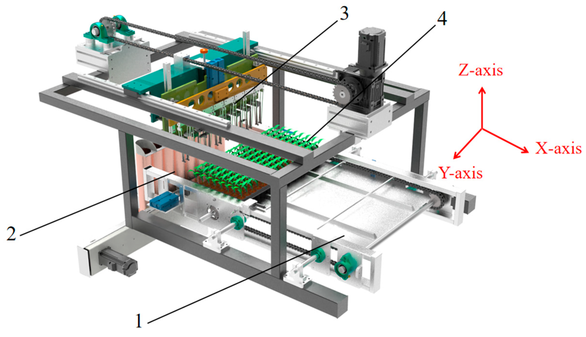
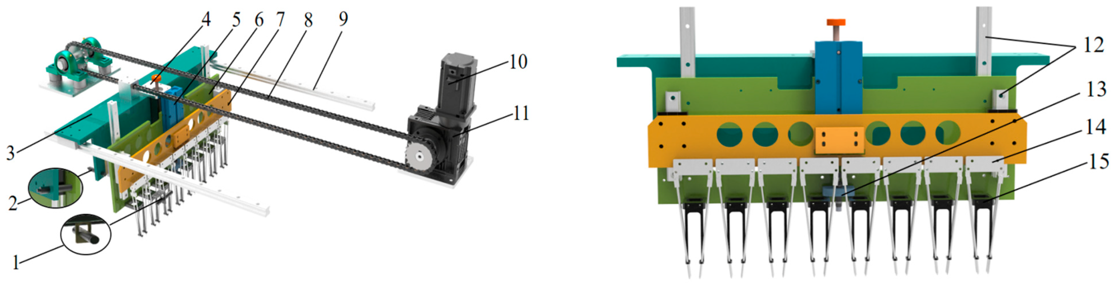
2.1. The Structural Composition of the Seedling Picking Mechanism

The whole-row reciprocating seedling picking system of the automatic transplanter consists of a whole-row reciprocating seedling picking mechanism, a seedling tray conveying mechanism, a seedling separation mechanism, and a 128-hole seedling tray (8 rows and 16 columns). The system’s length, width, and height are 140 mm, 96 mm, and 52 mm, respectively, as shown in Figure 2.
The seedling picking mechanism (SPM) is mainly composed of a stepper motor (SM), a decelerator, a mobile fixed plate, a driving chain, a lead screw stepper motor (LSSM), a lifting cylinder, a lifting fixed plate, an end effector fixed plate, seedling picking end effectors (SPEE), a guide rail slider mechanism in the X-axis and Z-axis directions, a seedling pushing ring, and zero position sensors in the X-axis and Z-axis directions, as shown in Figure 3. The SM drives the SPM to reciprocate in the X-axis direction between the seedling picking and seedling throwing positions through the driving chain, and the moving distance increases row by row. The LSSM and the lifting cylinder drive the entire row of SPEE through the lifting fixed plate and the end effector fixed plate to perform seedling picking and throwing operations.

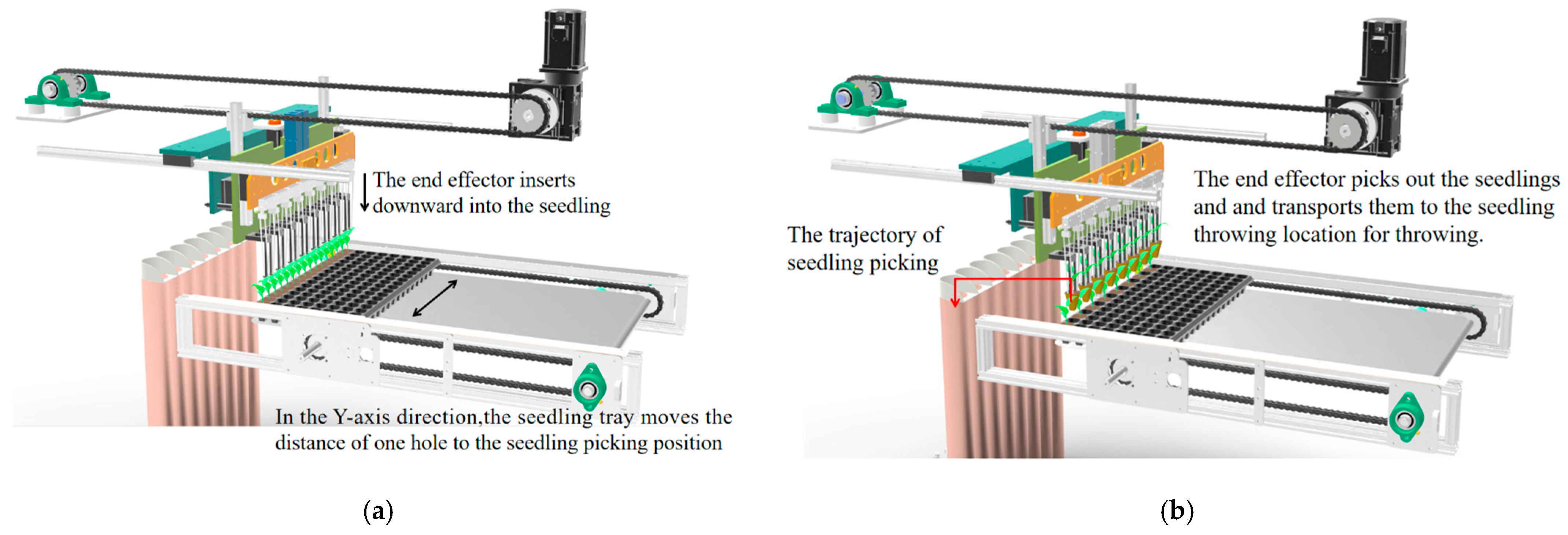
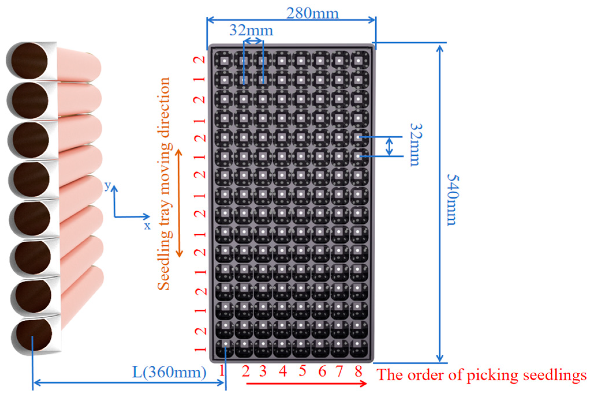
2.2. The Working Principle of the Seedling Picking Mechanism

The working principle of the SPM is shown in Figure 4. The SPM first performs a reset action. The SM drives the SPM to move to the zero position (seedling picking position) in the X-axis direction through the X-axis guide slider mechanism. When the X-axis zero position sensor senses the SPM, the SPM stops moving. The LSSM drives the lifting fixed plate to move to the zero position in the Z-axis direction through the Z-axis guide slider mechanism. When the Z-axis zero position sensor senses the lifting fixed plate, the lifting fixed plate stops moving, and the reset is completed. The seedling tray is placed on the seedling tray conveying mechanism, which will transport the seedling tray to the seedling picking position, and then, the seedling tray conveying mechanism will no longer move in the X-axis direction. The LSSM drives the lifting fixed plate to move the set distance in the negative direction of the Z-axis through the Z-axis guide slider mechanism, and then, the lifting cylinder pushes out the piston and drives the end effector fixed plate to move in the negative direction of the Z-axis through the Z-axis guide slider mechanism so that the entire row of SPEE moves in the negative direction of the Z-axis, and the clamping needle is inserted into the seedling to pick the seedling. The LSSM drives the lifting fixed plate to move in the positive direction of the Z-axis to the zero position in the Z-axis direction through the Z-axis guide slider mechanism, and then, the whole row of SPEE picks the seedlings, and the seedling picking is completed. There are 16 seedlings in a row of a 128-hole seedling tray. Due to the method of picking seedlings with holes spaced apart, 8 seedlings can be picked in one seedling picking action, and two seedling picking actions are required for one row of seedlings. After completing the first seedling picking action, the seedling tray conveying mechanism will move the distance of one hole in the Y-axis direction and perform the seedling picking action for the second time to complete the seedling picking action for one row of seedlings. Then, the seedling tray conveying mechanism will move the distance of one hole in the Y-axis direction in the opposite direction, waiting for the seedling picking action for the next row of seedlings. When picking seedlings from the same row of seedlings, the displacement of the SPEE in the X-axis direction is consistent. When picking the seedlings from the next row, the moving distance of SPEE in the X-axis direction is increased by the distance of one hole on the basis of the displacement of the previous row, and the cycle is repeated until the action of picking a tray of seedlings is completed.

2.3. The Structural Composition of the Seedling Picking Mechanism

Vegetable seedling trays usually have 128 holes (8 rows and 16 columns). The total length of the tray is 540 mm, the total width is 280 mm, the height is 42 mm, and the weight is about 150 g. The upper surface size of a single hole is 32 mm × 32 mm, the lower surface size is 15 mm × 15 mm, and the center distance between adjacent holes is 32 mm.
When picking seedlings, the SPEE only performs reciprocating motion in the X-axis direction, and the Y-axis direction is fixed. The seedling tray is fixed in the X-axis direction. Since there are 16 seedlings in each row of the seedling tray, the whole row of SPEE needs to perform two seedling picking actions to complete the seedling picking operation of a row of seedlings. After each row of seedlings completes the first seedling picking operation, the seedling tray conveying mechanism moves the seedling tray along the Y-axis direction by only the distance of one hole (32 mm), and then moves back to the original position after a row of seedlings is picked. The action and displacement are fixed, so the positioning accuracy requirements of the seedling tray conveying mechanism along the Y-axis direction can be ignored. The seedling picking end effector performs row-by-row reciprocating movement in the X-axis direction. Each row of seedlings performs two reciprocating movements of the same distance. The movement distance of the next row of seedlings increases the distance of one hole based on the displacement of the previous row, as shown in Figure 5. The seedling picking end effector performs a fixed displacement reciprocating movement in the Z direction, and the displacement is small, so the impact on the running stability and positioning accuracy in the Z direction can be ignored. Therefore, this paper only studies the running stability and positioning accuracy of the seedling picking end effector in the X-axis direction.

2.3.1. Analysis of Motion Stability

The design requirement of the SPM is that the seedling picking efficiency is ≥22 plants/row/min. The smoothness of the movement process must be ensured when the whole row of SPEE is operating to avoid unstable operations due to vibration or impact during movement, which will affect the movement stability of the seedling picking operation and reduce the success rate of seedling picking.

2.3.2. Analysis of Control Accuracy

In the X-axis direction, the whole row of SPEE is driven by a stepper motor to move back and forth between the seedling picking position and the seedling throwing position. When picking the first row of seedlings, the displacement is L (360 mm), and when picking the second row of seedlings, the displacement is L + 32 mm. The displacement of the next row of seedlings when picking the seedlings is the displacement of the previous row of seedlings plus 32 mm, until the seedling picking is completed. A linear encoder is used to collect the displacement data of the end effector in real time, and the precise movement of the SPEE is controlled by the control system.
SPEE are of a two-finger four-needle type. When picking seedlings, they need to be inserted into the center of the hole. The spacing between the two clamp needles is 12 mm, and the insertion depth is 36 mm. Combined with the upper surface size of the seedling tray hole of 32 mm and the lower surface size of 15 mm, the allowable error value of SPEE in the X-axis direction is ±2 mm. In actual operation, the positioning error of the whole row of SPEE will be superimposed with the increase in the number of reciprocating movements, causing the SPEE displacement to deviate from the preset value, making it impossible for the clamping needle to pick the seedlings, and inserting into the side wall of the seedling tray, causing damage to the seedling tray structure and failure to pick the seedlings. In the X-axis direction, the SM controls the motion displacement trajectory of the whole row of SPEE, and its control accuracy directly determines the positioning accuracy of the SPEE. Therefore, it is necessary to build a closed-loop real-time feedback control to ensure the accurate positioning of the whole row of SPEE in the X-axis direction.

3. The Design of a Motion Control System for the Seedling Picking Mechanism

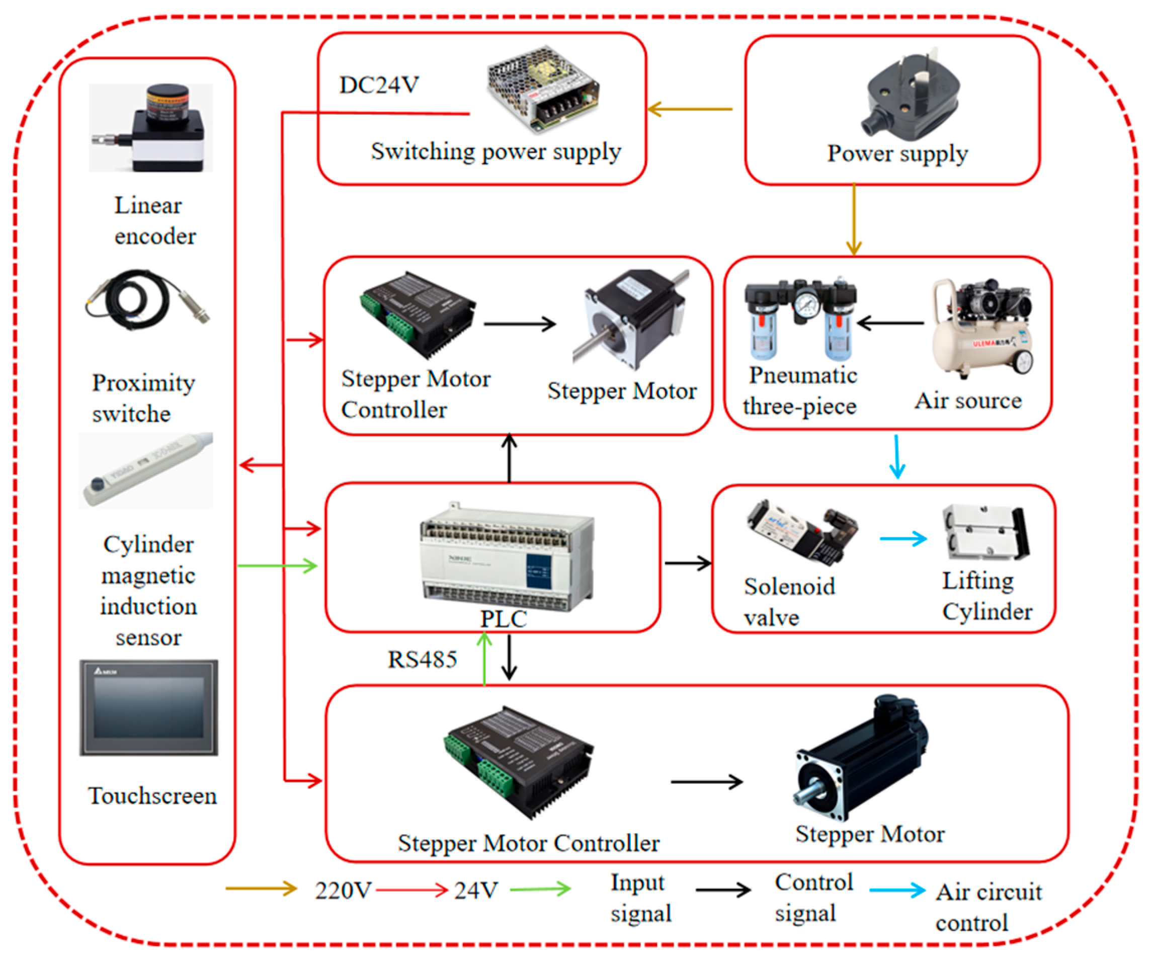
3.1. The Design of the Control System Hardware

The SPM is mainly composed of a PLC controller (Q172DSCPU, Mitsubishi Electric Co., Ltd., Tokyo, Japan), zero point sensors (NJK-5002C Hall proximity switch, Zhejiang Huchuang Electric Co., Ltd., Wenzhou, China), a linear encoder (BRT38, Shenzhen Bright Technology Co., Ltd., Shenzhen, China), a lifting cylinder magnetic induction sensor (DMSG, Ningbo AirTac Automation Industrial Co., Ltd., Ningbo, China), a lifting cylinder (TN25×50S, Ningbo AirTac Automation Industrial Co., Ltd., Ningbo, China), a seedling tray conveying the SM in the X-axis direction and an SPM SM in the X-axis direction (57CME26, Shenzhen Leadshine Intelligent Control Co., Ltd., Shenzhen, China), a seedling tray conveying the LSSM in the Y-axis direction and an SPM LSSM in the Z-axis direction (57CME23-T10×16, Shenzhen Leadshine Intelligent Control Co., Ltd., Shenzhen, China), and a stepper motor driver (CL57C V2.0, Shenzhen Leadshine Intelligent Control Co., Ltd., Shenzhen, China).
The Hall proximity switch, linear encoder, and magnetic induction sensor are used as signal input sources. The PLC controller processes the received input signals and sends them to the stepper motor driver and cylinder solenoid valve in sequence, driving the stepper motors in the X-axis, Y-axis, and Z-axis directions and driving the lifting cylinder to perform corresponding actions. The PLC controller and linear encoder form a feedback closed-loop control system to achieve smooth and accurate operation of the entire row of seedling picking. The hardware diagram is shown in Figure 6.
Since the motion control system uses the PLC controller Q172DSCPU of Mitsubishi Electric Co., Ltd. of Japan, the programming software uses the matching MT Developer2, and the touch screen uses the GT2310-VTBA of Siemens AG of Germany, Berlin. The control interface is shown in Figure 7.

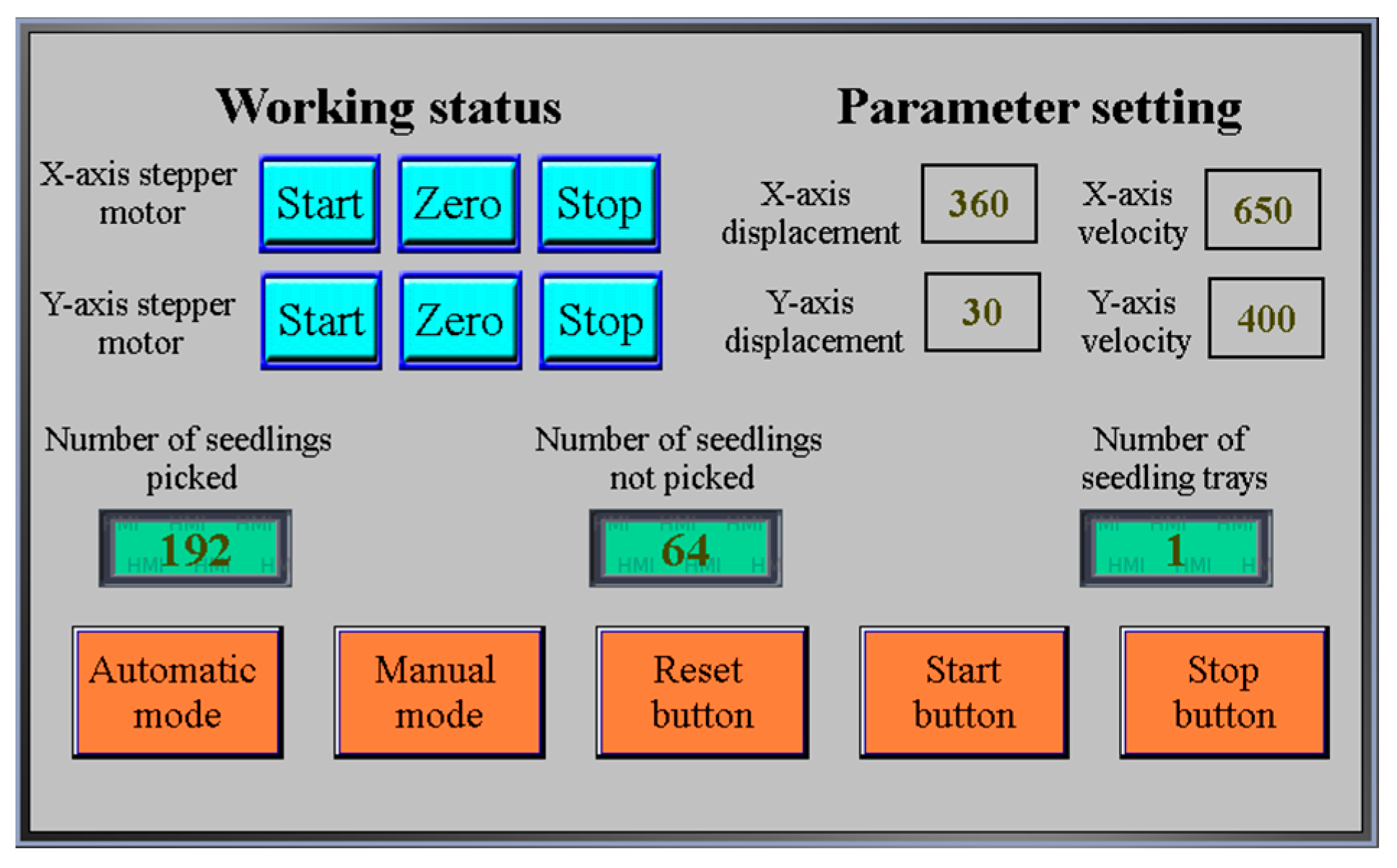
3.2. The Design of the Control System Software

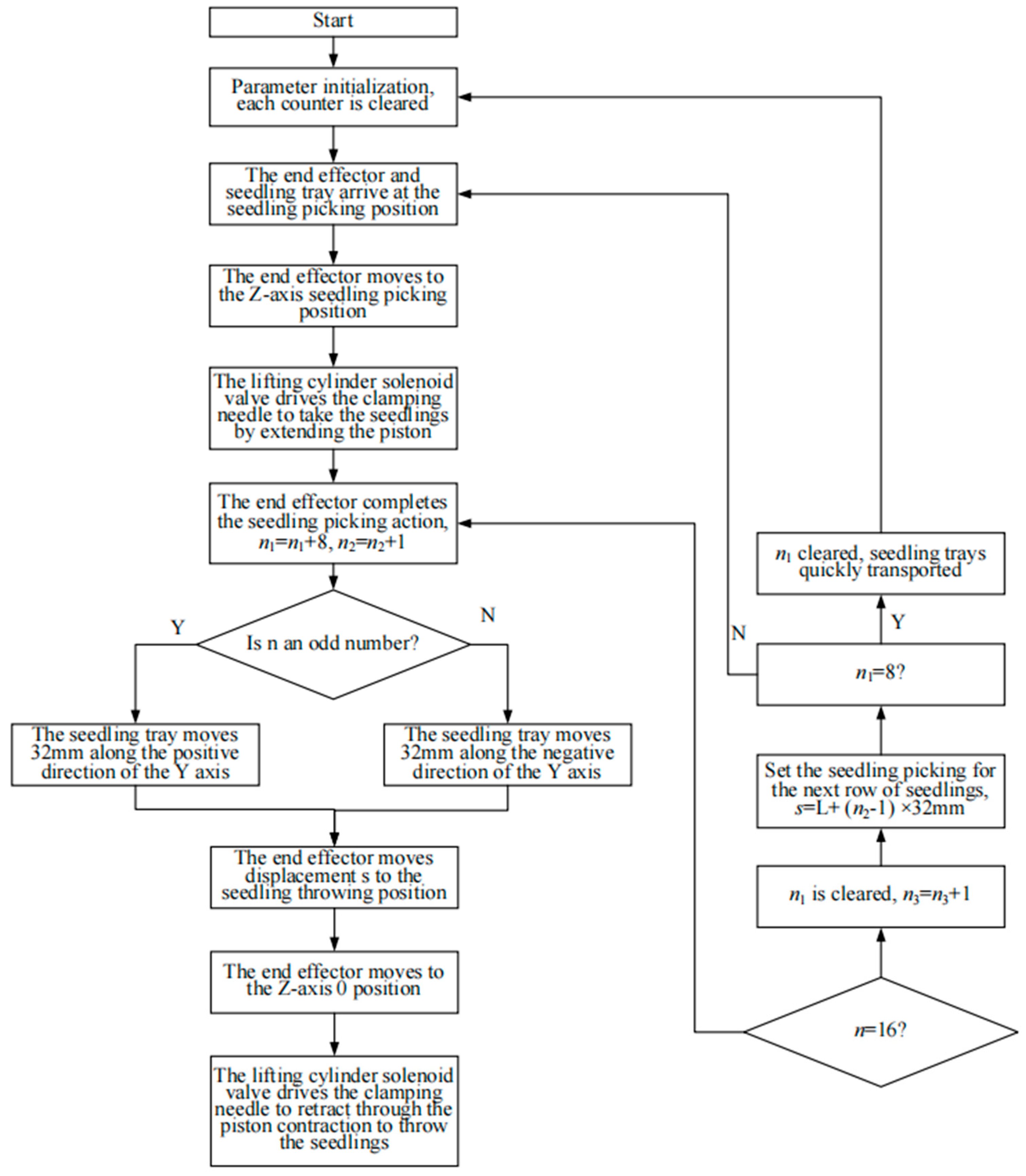
3.2.1. Design of Timing Control for Seedling Picking and Throwing

The action sequence of each driving mechanism is shown in Figure 8. The LSSM drives the SPEE to move along the negative direction of the Z-axis to the specified position, and then, the lifting cylinder extends the piston, the piston drives the clamping needle to insert the seedling, and the LSSM drives the SPEE to pick the seedling along the positive direction of the Z-axis to complete the seedling picking action. The SM drives the SPEE to move along the X-axis to the seedling throwing position, and the LSSM drives the SPEE to move in the negative direction of the Z-axis. The lifting cylinder contracts the piston, and the piston drives the clamping needle to contract along the positive direction of the Z-axis. The seedling pushing ring pushes the seedling out to complete the seedling throwing action, and a seedling picking and seedling throwing cycle is completed.

3.2.2. Design of the Process of the Seedling Picking and Throwing Control System

The main program flow chart of the seedling picking and throwing control system is shown in Figure 9. s represents the displacement of the SM driving SPEE to move between the seedling picking and throwing positions through the chain transmission mechanism, n is the number of seedlings picked, n1 is the number of seedlings picked in each row, and n2 is the row counter. Since there are 16 columns of seedlings in a row, the SPM can pick 8 seedlings at a time, so the number of seedlings picked in each row is 8 or 16. This study uses a 128-hole seedling tray, so the number of rows is 1 to 8. As shown in Figure 5, the displacement of the SPM s = L + (n2 − 1) × 32 mm. The initial value of each counter is 0.
The system is turned on and reset. At this time, SPEE are located in the X direction and have reached the seedling picking position. The PLC outputs a signal, and the LSSM drives the SPEE to move to the specified position along the negative direction of the Z-axis through the Z-axis guide slider mechanism. Then, the lifting cylinder solenoid valve is turned on, so the cylinder pushes out the piston, and the piston drives the clamping needle to insert the seedling. The PLC sends a signal to drive the LSSM to move a certain distance along the positive direction of the Z-axis through the Z-axis guide slider mechanism to pick the seedling and complete the seedling picking operation. Next, the PLC sends a signal, the SM drives the SPEE to move to the seedling throwing position through the X-axis guide slider mechanism, and the LSSM drives the SPEE to move a certain distance along the positive direction of the Z-axis through the Z-axis guide slider mechanism. Then the lifting cylinder solenoid valve is closed, and the piston contracts to drive the clamping needle to contract to cast the seedling, and a seedling throwing cycle ends. SPEE move to the seedling picking position for the next cycle of operation.

3.3. A Control Algorithm for Seedling Picking Motion Based on Planned S-Curve Acceleration and Deceleration

When the SPM is operated based on the S-curve acceleration and deceleration motion control algorithm, the speed changes gradually over time and presents an S-shaped curve, which can achieve a smooth motion process [27]. Compared with the trapezoidal and exponential acceleration and deceleration motion, the S-curve acceleration and deceleration control algorithm has better motion control performance, and the continuous acceleration change makes the speed transition smoother, reduces the vibration impact caused by the acceleration mutation, and improves the motion stability of the SPM.
The complete seven-segment S-curve motion of the SPM includes the acceleration stage (T1), uniform acceleration stage (T2), deceleration stage (T3), uniform speed stage (T4), acceleration and deceleration stage (T5), uniform deceleration stage (T6), and deceleration and deceleration stage (T7). Figure 10 shows the speed, acceleration, and jerk curves of the complete seven-segment S-curve acceleration and deceleration algorithm. In the figure, tk represents the moment of the kth motion transition stage, Tk represents the time of the kth operation stage, vs represents the initial speed, vmax represents the maximum speed of the operation stage, amax represents the maximum acceleration during the S-curve acceleration and deceleration motion, and jmax represents the maximum acceleration allowed by the system.

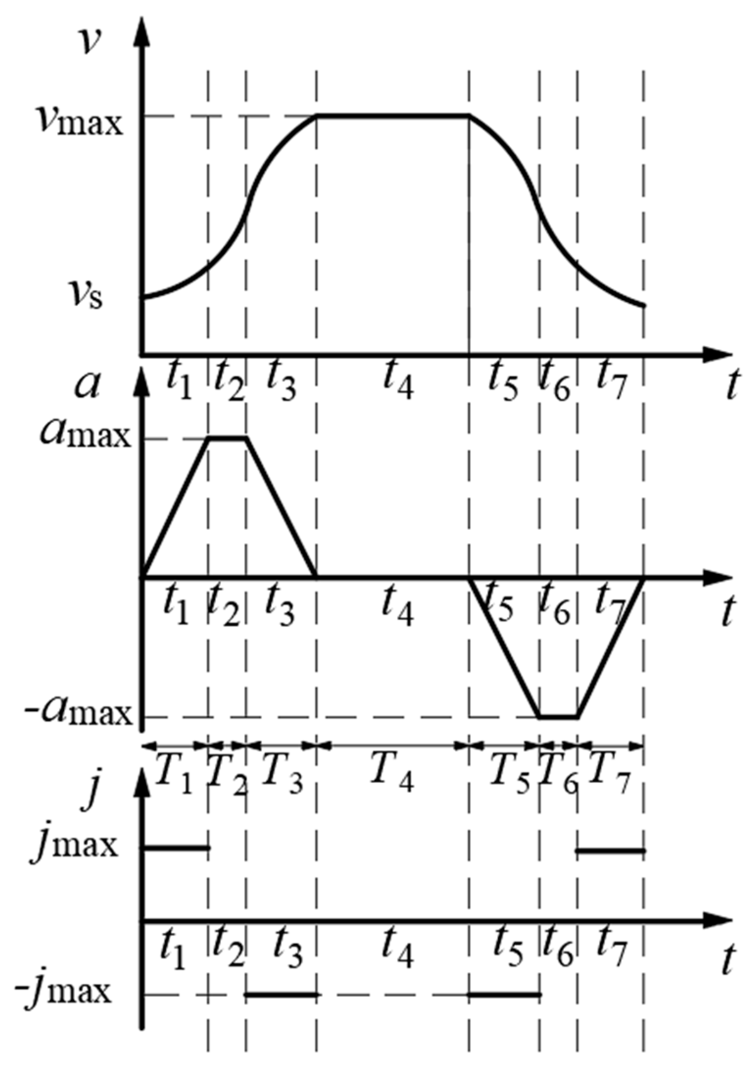
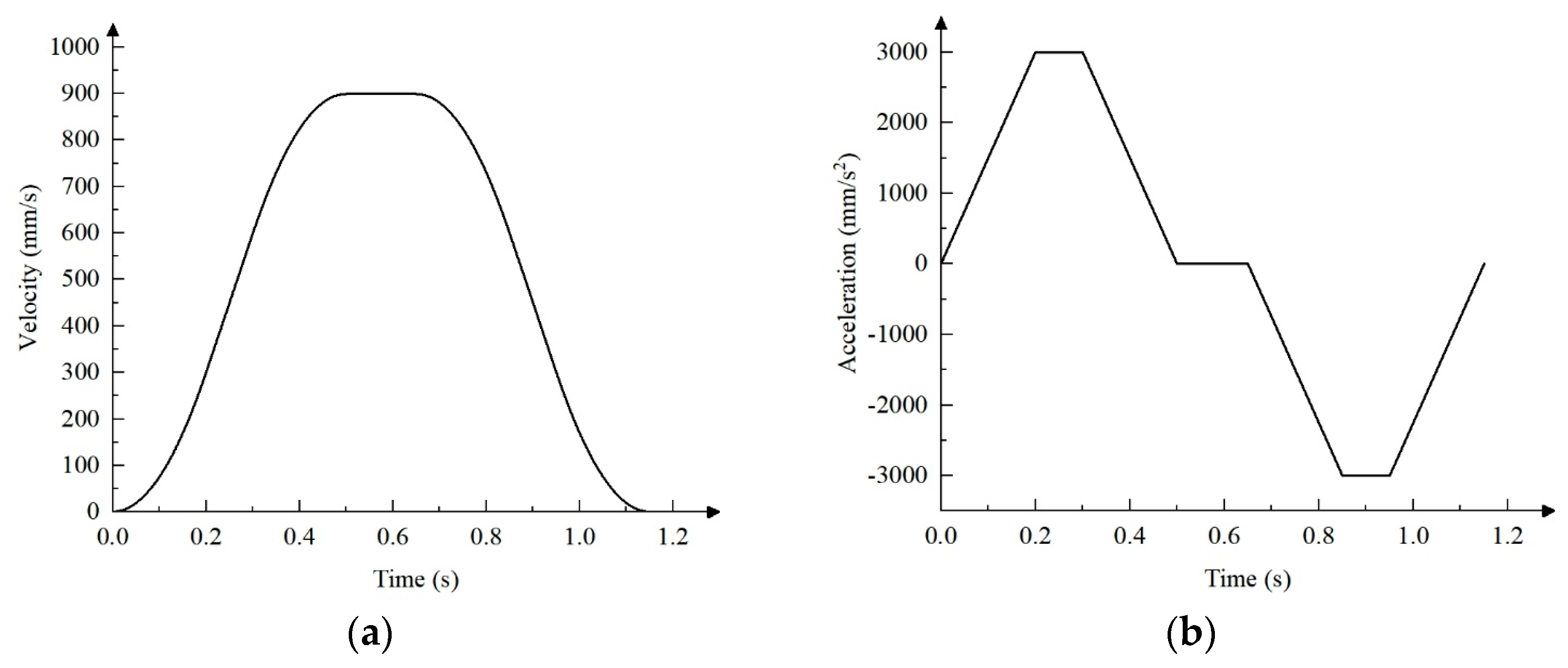
3.3.1. The Design of S-Curve Acceleration and Deceleration Motion

For the reciprocating motion of the SPM in the X-axis direction, the initial velocity vs and the final velocity ve are 0. To ensure the shortest running time, the acceleration and deceleration sections of the velocity curve should be completely symmetrical, as shown in Figure 8, T1 = T3 = T5 = T7, T2 = T6, J1 = J3 = J5 = J7. In order to simplify the calculation, vk is used to represent the velocity at the transition point of each stage of tk, sk is used to represent the displacement at the time of tk, and jk is represented as the acceleration of the acceleration and deceleration stage. The expressions for jerk, acceleration, velocity, and displacement can be obtained:
j ( t ) = j max t 0 t < t 1 0 t 1 t < t 2 j max t 2 t < t 3 0 t 3 t < t 4 j max t 4 t < t 5 0 t 5 t < t 6 j max t 6 t < t 7
a ( t ) = j max t t 0 t < t 1 a max t 1 t < t 2 a max j max ( t t 2 ) t 2 t < t 3 0 t 3 t < t 4 j max ( t t 4 ) t 4 t < t 5 a max t 5 t < t 6 a max + j max ( t t 0 ) t 6 t < t 7
v ( t ) = 1 2 j max t 2 t 0 t < t 1 v 1 + j T 1 ( t t 1 ) t 1 t < t 2 v 2 + j T 1 ( t t 2 ) 1 2 j ( t t 2 ) 2 t 2 t < t 3 v 3 t 3 t < t 4 v 4 1 2 j ( t t 4 ) 2 t 4 t < t 5 v 5 j T 5 ( t t 5 ) t 5 t < t 6 v 6 j T 5 ( t t 6 ) + 1 2 j ( t t 6 ) 2 t 6 t < t 7
s ( t ) = 1 6 j max t 3 t 0 t < t 1 s 1 + v 1 ( t t 1 ) + 1 2 j max T 1 ( t t 1 ) 2 t 1 t < t 2 s 2 + v 2 ( t t 2 ) + 1 2 j max T 1 ( t t 2 ) 2 1 6 j max ( t t 2 ) 3 t 2 t < t 3 s 3 + v 3 ( t t 3 ) t 3 t < t 4 s 4 + v 4 ( t t 4 ) 1 6 j max ( t t 4 ) 3 t 4 t < t 5 s 5 + v 5 ( t t 5 ) 1 2 j max T 1 ( t t 5 ) 2 t 5 t < t 6 s 6 + v 6 ( t t 6 ) 1 2 j max T 1 ( t t 6 ) 2 + 1 6 j max ( t t 6 ) 3 t 6 t < t 7
The above formula is the expression of jerk, acceleration, velocity, and displacement in each motion stage under the complete seven-segment S curve. However, in the actual seedling picking process, the motion control system may not need to run the seven stages completely due to constraints such as a short acceleration or deceleration distance and high maximum allowable speed. In addition, since the type of curve used does not match the actual motion, the system will have drawbacks such as increased calculation, slower response speed, and unstable operation. Therefore, in order to ensure the smooth movement of the SPM, the S-curve acceleration and deceleration movement can be planned according to the displacement s from the seedling picking position to the seedling throwing position and the maximum speed vmax, maximum acceleration amax, and maximum jerk jmax allowed by the SPM.
In order to obtain the total displacement s of the SPM from the seedling picking position to the seedling throwing position, T7 = tt6 and the displacement sk at each stage of the movement process are substituted into the displacement expression of the t6t7 stage in Formula (4), and the total displacement calculation formula can be obtained:
s = 2 j max T 1 + 3 3 j max T 1 T 2 2 + j max T 1 T 4 2 + j max T 1 T 2 + 2 j max T 1 T 2 T 4
Substituting v1, v2 and T3 = tt2 in the speed expression of Formula (3) into the speed expression corresponding to the t2t3 stage and substituting T1 = tt0 into the acceleration expression of the t0t1 stage in Formula (2), the maximum speed and maximum acceleration calculation formulas under the conditions of the S-curve acceleration and deceleration control algorithm can be obtained, respectively:
v max = v 3 = j max T 1 2 + j max T 1 T 2 a max = A = j max T 1
As shown in Figure 8, the total time of the seedling picking and seedling throwing process can be expressed as:
T = 4 T 1 + 2 T 2 + T 4
In the process of seedling picking and throwing, the displacement is s. To minimize the total time T, the maximum speed vmax, maximum acceleration amax, and maximum jerk jmax in the X-axis direction can be obtained according to the requirements of the seedling picking and throwing operation and the parameters of the driving mechanism. According to the corresponding mathematical expressions obtained above, the problem of solving for the minimum value of the total time T can be transformed into an objective function optimization problem with constraints, as shown in Formula (8):
Objective   Function T min = min ( 4 T 1 + 2 T 2 + T 4 ) Constraints s . t v max j max T 1 2 + j T 1 T a max j max T 1 s = 2 j max T 1 3 + 3 j max T 1 2 T 2 + j max T 1 2 T 4 + j max T 1 T 2 2 + j max T 1 T 2 T 4
When the SPM moves in the X-axis direction, the displacement will gradually increase. Therefore, for the nonlinear programming problem of Formula (8) for different displacements s, different values of vmax and amax are assumed multiple times according to the system operation restrictions to solve. According to displacement s of SPEE in the X-axis direction, combined with the solution results, the S-curve acceleration and deceleration motion types can be divided into seven-segment and six-segment curves.
As shown in Figure 8, when the displacement s > sa + sb, the movement of SPEE in the X-axis direction can reach the maximum acceleration amax and maximum speed vmax limited by the system. sa is the total displacement in the acceleration stage, and sb is the total displacement in the deceleration stage. Since the curve in this case is symmetrical, sa = sb, s > 2sa = 2sb. Therefore, the total movement time under the acceleration and deceleration conditions of the seven-segment S-curve is planned and calculated according to Formula (8).
The total displacement during the acceleration phase is shown in Formula (9):
s a = s 3 = j max T 1 ( T 1 + T 2 ) ( T 1 + 1 2 T 2 ) = v max ( T 1 + 1 2 T 2 )
From Formulas (5), (8), and (9), we can get the relationship between the time of each stage of the movement of the SPM, as shown in Formula (10):
T 1 = a max j max T 2 = v max a max a max j max T 4 = s s a s b v max = s 2 s a v max = s v max a max j max v max a max
Substituting Formulas (8)–(10) into Formulas (5) and (6) yields:
s a = j max v max 2 + v max a max 2 2 j max a max T = 4 T 1 + 2 T 2 + T 4 = s v max + a max j max + v max a max
When the uniform motion stage is missing during the motion process, the S-curve acceleration and deceleration motion becomes a six-stage motion. The 6-stage S-curve acceleration and deceleration motion has the following characteristics: the highest speed vg achieved during the motion process is less than or equal to the maximum speed vmax allowed by the system, and when the total motion displacement 2sa′s ≤ 2sa, the acceleration can reach the maximum acceleration amax allowed by the system, where sa′ is the sum of the motion distances in the acceleration stage and the deceleration stage.
From the motion curve in Figure 8 and the displacement expression in Formula (8), the expression of sa′ can be obtained:
s a = s 3 s 2 + s 1 = j max T 1 3 + j max T 1 T 2 2
Under the six-stage condition, the acceleration during motion can reach the maximum value, and there is no uniform motion stage. According to Formula (5) for displacement s, the time expression of the corresponding motion stage can be obtained:
T 1 = a max j T 2 = a max 4 J max 2 + 4 a max s 3 a max 2 j max 2 a max T 4 = 0
Therefore, the total exercise time T under the six-stage condition can be calculated according to the above formula:
T = 4 T 1 + 2 T 2 + T 4 = 4 a max j max + a max 4 J max 2 + 4 a max s 3 a max 2 j max a max
According to the structure and performance requirements of the SPM, the maximum speed vmax = 900 m/s, the maximum acceleration amax = 3000 mm/s2, and the maximum jerk Jmax = 15,000 mm/s3 are determined. According to the above parameter values, combined with the calculation formulas for sa, sb, and sa′ in the previous chapter, it can be determined that sa = sb = 225 mm. In order to enable the SPM to always move smoothly under the control of the S-curve acceleration and deceleration algorithm during operation, the SPM movement displacement is divided, and the size relationship between s and 2sa, 2sa′ is compared to select the appropriate type of S-curve acceleration and deceleration movement.
When SPEE pick the first row of seedlings, the distance between the seedling picking position and the seedling throwing position is s = L = 360 mm, sa′ = 156 mm. When SPEE pick the third row of seedlings, distance s between the seedling picking position and the seedling throwing position is 360 + 2 × 32 = 424 mm, sa′ = 173.4 mm. Therefore, when SPEE pick the first three rows of seedlings, 2sa′s ≤ 2sa is met. When SPEE pick the seedlings in the fourth row, the distance between the seedling picking position and the seedling throwing position is s = 360 + 3 × 32 = 456 mm, so when SPEE pick the seedlings in the fourth to eighth rows, s > 2sa, that is, s > 450. In summary, when SPEE take the seedlings in the first to third rows, the seven-segment S-curve acceleration and deceleration algorithm is used for motion control, and when SPEE take the seedlings in the fourth to eighth rows, the six-segment S-curve acceleration and deceleration algorithm is used for motion control.

3.3.2. The Simulation Test and Analysis of the S-Curve Acceleration and Deceleration Control Algorithm

According to the planned six-segment and seven-segment S-curve acceleration and deceleration motion control algorithms and related motion parameters, the motion curves of the two S-curve acceleration and deceleration control algorithms were simulated and analyzed using MATLAB2024a software. Displacement s when SPEE pick the third row of seedlings is selected to verify the six-segment S-curve acceleration and deceleration motion control algorithm, and displacement s when SPEE pick the eighth row of seedlings is selected to verify the seven-segment S-curve acceleration and deceleration motion control algorithm. The two selected displacements are both the longest distances under the corresponding S-curve motion conditions, which can better reflect the motion characteristics under the corresponding curve type.
When SPEE pick the third row of seedlings, s = 424 mm. The relationship curve between the speed, acceleration, and time of SPEE under the condition of six-segment S-curve acceleration and deceleration control algorithm is shown in Figure 11, where T1 = T3 = T5 = T7 = 0.2 s, T2 = T6 = 0.09 s, T4 = 0, and the total time T = 0.98 s.
When SPEE pick the eighth row of seedlings, s = 584 mm. The relationship curve between the speed, acceleration, and time of SPEE under the condition of the seven-segment S-curve acceleration and deceleration control algorithm is shown in Figure 12, where T1 = T3 = T5 = T7 = 0.2 s, T2 = T6 = 0.10 s, T4 = 0.15 s, and the total time T = 1.15 s.
By simulating the S-curve acceleration and deceleration motion control algorithm, the consistency between the S-curve acceleration and deceleration motion curve planned according to the target parameters and the motion curve and motion parameter requirements under the general mathematical theory is verified, proving that the planned S-curve can still maintain the original motion characteristics.
In order to verify the feasibility of the planned S-curve acceleration and deceleration motion control algorithm in terms of motion smoothness and seedling picking efficiency, the speed and acceleration of SPEE under the conditions of trapezoidal acceleration and deceleration motion control algorithm were simulated. To ensure the reliability of the comparison results, the maximum speed and maximum acceleration were kept consistent with the parameters in the S-curve acceleration and deceleration motion control algorithm simulation. The relationship curves of speed, acceleration, and time of SPEE under the condition of trapezoidal acceleration and deceleration control algorithm when s = 584 mm were compared and analyzed, as shown in Figure 13.
By comparing the simulation results, it can be seen that when the displacement is 584 mm, under the condition of trapezoidal acceleration and deceleration motion, the speed greatly reduces the stability of the seedling picking motion process due to astep change in acceleration. Under the conditions of the S-curve acceleration and deceleration control algorithm, the acceleration is continuous and the speed transitions smoothly during the SPEE motion, which avoids the impact and vibration caused by sudden acceleration changes during the seedling picking process and ensures the stability of the seedling picking process. The displacement corresponding to 8 rows of seedlings was simulated. The total time of 8 seedling transportation under the conditions of the S-curve acceleration and deceleration control algorithm and trapezoidal motion control algorithm was 8.23 s and 6.59 s, respectively, and the time for SPEE to perform clamping action and seedling throwing action was 0.7 s, respectively. Under the conditions of the S-curve acceleration and deceleration control algorithm and the trapezoidal motion control algorithm, the total operation time for a whole tray of seedlings was 8.23 × 2 + 0.7 × 32 = 38.86 s, and 6.59 × 2 + 0.7 × 32 = 35.58 s respectively, and the seedling picking efficiency was 25 plants/row/min and 27 plants/row/min, respectively. Although the efficiency is slightly lower than that of the trapezoidal motion control algorithm, it meets the design requirement of seedling retrieval efficiency ≥22 plants/row/min, and the operation is more stable.

3.4. The Control Algorithm of Seedling Picking Motion Positioning Based on Fuzzy PID

The fixed-parameter PID control algorithm is subject to the limitations of static parameter configuration and has obvious defects in dynamic response speed, load disturbance resistance, and parameter adaptation. In comparison, fuzzy control systems are more robust and achieve dynamic compensation through membership functions and fuzzy rules. They are particularly suitable for nonlinear control systems with time-delay characteristics [28,29]. Therefore, by constructing a fuzzy PID control algorithm and combining it with the S-curve acceleration and deceleration motion control algorithm, not only can the phase lag in the acceleration phase of the S-curve and the overshoot oscillation at the inflection point be quickly corrected, but also the dynamic compensation of the residual error of trajectory tracking during the deceleration process can be achieved.

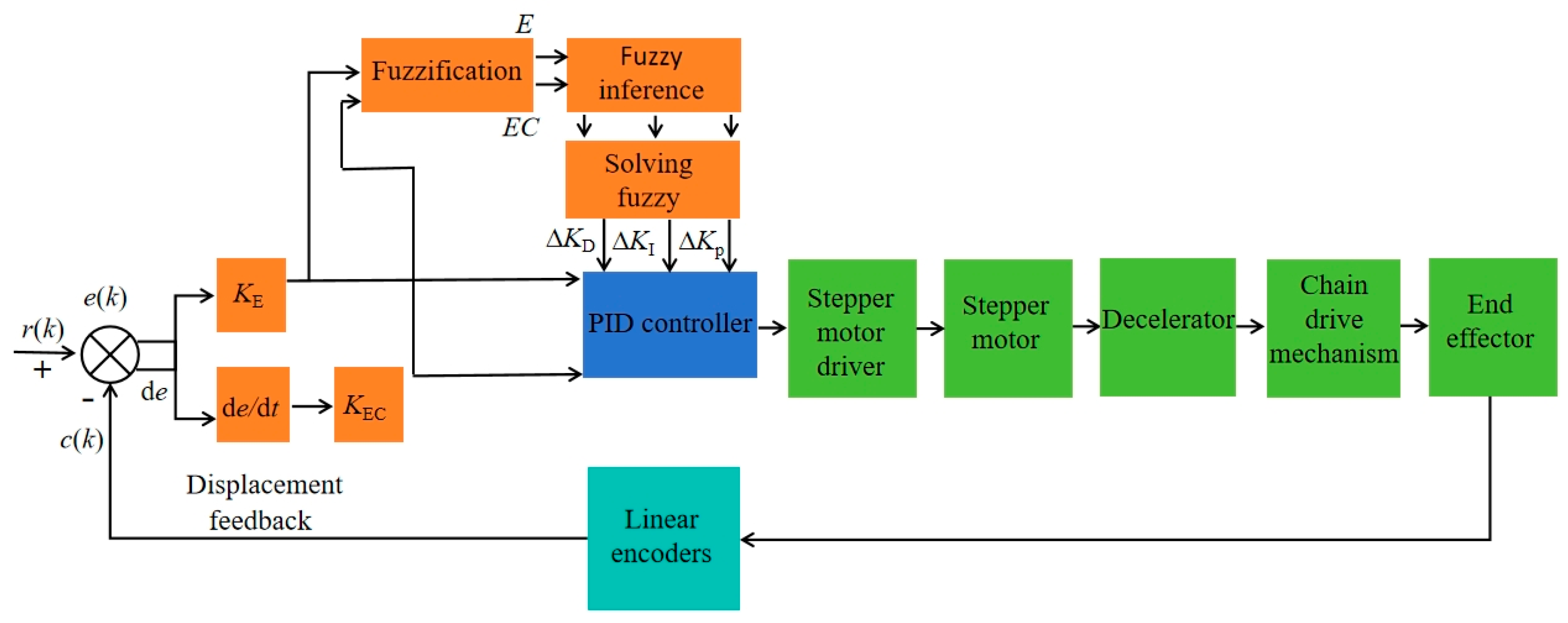
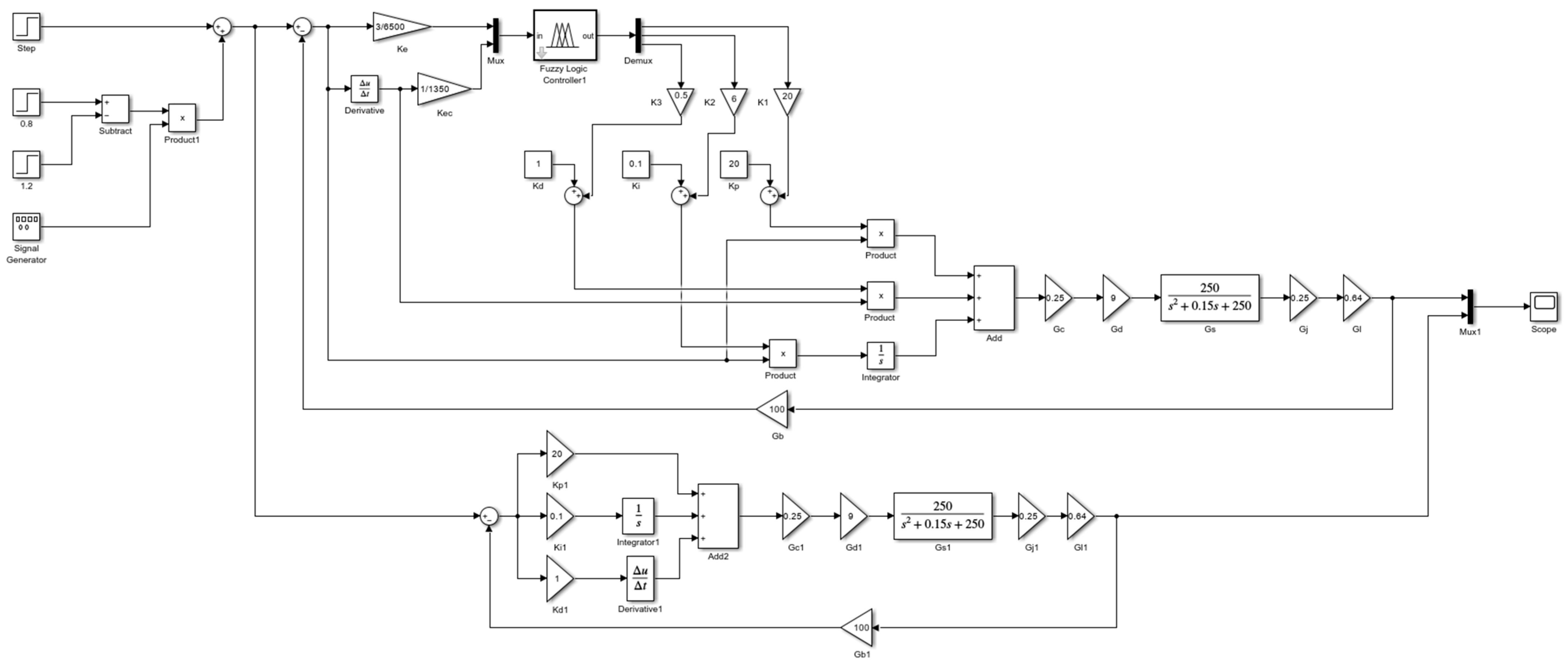
3.4.1. Design of the Fuzzy PID Control System Structure

The SPM fuzzy PID closed-loop positioning control system mainly consists of two parts: one is the PID control with fixed parameters, and the other is the fuzzy control. The control system collects the SPEE displacement feedback in real time, performs dynamic error analysis on it and the set displacement, and maps the system deviation and the deviation change rate to the membership function based on fuzzy rules, so that the PID parameters can be corrected online to achieve rapid response and accurate positioning of the whole row of SPEE.
The linear encoder uses the actual measured displacement c(k) as the actual output value of the controller and r(k) as the input given value. The expression of the position error e(k) is:
e ( k ) = r ( k ) c ( k )
The fixed-parameter PID control algorithm can be expressed as:
u ( k ) = K p e ( k ) + K I 0 k e ( k ) d k + K D d e ( k ) d k
where Kp is the proportional coefficient, KI is the integral coefficient, KD is the differential coefficient, u(k) is the system output, 0 k e ( k ) d k is the accumulated error, and d e ( k ) d k is the error change rate.
The fuzzy PID control algorithm processes the system error and the error change rate through the set fuzzy rules and corrects the PID parameters Kp, KI, and KD. The correction formula is:
K P = K P + K P K I = K I + K I K D = K D + K D
where Kp, KI, and KD are the set parameter values in the PID controller; ∆KP, ∆KI, and ∆KD are the online correction values.
The block diagram of the seedling picking motion positioning control system based on fuzzy PID is shown in Figure 14.

3.4.2. Design of a Fuzzy PID Controller

The positioning of SPEE is mainly controlled by the displacement error e. Therefore, the fuzzy controller takes the displacement error e and the displacement error change rate de as input variables, and ∆KP, ∆KI, and ∆KD as output variables. The domain of the displacement error e is defined as [−20, 20], the domain of the displacement error change rate de is defined as [−50, 50], the domain of ∆KP is defined as [−20, 20], the domain of ∆KI is defined as [−10, 0], and the domain of ∆KD is defined as [−2, 2]. The domains of the input linguistic variables E and EC are defined as [−3, 3] and [−3, 3], and the domains of the output linguistic variables KP, KI, and KD are defined as [−1, 1], [−1, 1], and [−1, 1]. Therefore, the proportional factor of the displacement error e is KE = 3/20, the proportional factor of the displacement error change rate de is KEC = 3/50, and the proportional factors of the output variables ∆KP, ∆KI, and ∆KD are K1 = 20, K2 = 10, and K3 = 2, respectively. The fuzzy rules and membership functions are designed and adjusted based on experience. Combined with a large amount of test data of the seedling picking mechanism positioning control system, the fuzzy control rule table is established by repeatedly testing and tuning the relationship between the system input (such as displacement error and its rate of change) and the output (correction value). The membership function uses a triangular membership function with a simple structure and strong real-time performance. This function is not only easy to implement but also convenient for adjusting the membership overlap range to meet the trade-off between control sensitivity and stability.
The five variable values of the input language and the output language are divided into seven levels, denoted as: {NB, NM, NS, ZO, PS, PM, PB}, which, respectively, represent {negative large, negative medium, negative small, zero, positive small, positive medium, positive large}. The fuzzy rules are shown in Table 1.

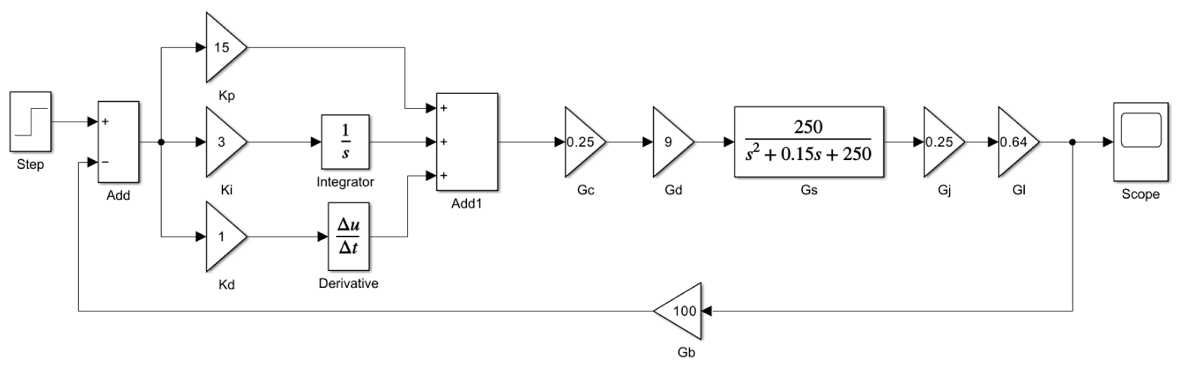
3.4.3. The Establishment of the Transfer Function of the Positioning Control System

The SM model is 57CME26, and the specific parameters are shown in Table 2.
Without considering eddy current loss and hysteresis effect, the two-phase voltage expressions of the motor are shown in Formulas (18) and (19).
u a = L d i a d t + R i a k e ω sin ( θ )
u b = L d i b d t + R i b k e ω sin ( N r θ )
where ua, ub are the voltages of the two phases of the motor, V; L is the inductance, mH; R is the resistance, Ω; ia, ib are the currents of the two phases of the motor; ke is the back electromotive force coefficient; ω is the angular velocity of the rotor, rad; Nr is the number of rotor teeth; t is the time, s.
According to the structural characteristics of the motor, the load torque during its operation can be ignored, and the dynamic balance formula of the motor is:
T e = 1 2 k T i a sin N r θ 1 2 k T i b sin N r θ λ J d ω d t + B ω = T e d θ d t = ω
With the angular displacement θi as the control quantity and θt as the target value, the angular error ∆θ = θiθt, and the control effect is the best when ∆θ = 0. Assuming the rated current is Ig and assuming the rated current is Ig, the expressions for the angular displacement at λ/2 and the two-phase current are:
θ = λ 2 + θ i a = I g + i a i b = I g + i b
where ∆ia and ∆ib are the two-phase armature current deviations, mA.
From the above formula, we can get Formula (22):
J d 2 ( θ ) d t 2 + B d ( θ ) d t + k T I g θ cos N r λ 2 + 1 2 k T I g θ cos N r λ 2 i a + i b = 0
When λ = 0, Formula (22) can be expressed as:
J d 2 θ i ( t ) d t 2 + B d θ g ( t ) d t + k T I g N r θ i ( t ) = k T I g N r θ t ( t )
Taking the first-order derivative of Formula (23), substituting d θ d t = ω and s = d ω i ( t ) d t into the formula, ωs is the actual rotation angle of the stepper motor, ωt is the target angular velocity of the stepper motor; then, we perform the Laplace transform to obtain Formula (24):
( s 2 J + s B + k T I 0 N r ) ω 1 ( s ) = k T I 0 N r ω t ( s )
By rearranging Formula (24), we can get the expression of the transfer function Gs(s) of the SM:
G s ( s ) = ω i ( s ) ω t ( s ) = k T I 0 N r J s 2 + s B J + k T I 0 N r J
Substituting the parameters in Table 1 into Formula (25), the specific expression of the transfer function Gs(s) of the stepper motor can be obtained as follows:
G s ( s ) = 250 s 2 + 0.15 s + 250
The chain drive mechanism converts the angular displacement of the stepper motor into a linear displacement of SPEE on the X-axis, which can be regarded as a proportional module. The expression of the transfer function Gn(s) is:
G l ( s ) = π D 1 360 = π × 73.14 360 = 0.64
where D1 is the pitch circle diameter of the sprocket, the sprocket model is 08B, the number of teeth is 18, and D1 is 73.14 mm.
The motor driver, reducer, and programmable controller are regarded as proportional modules, and their empirical transfer functions are Gd(s) = 9, Gj(s) = 0.25, and Gc(s) = 0.25, respectively; the encoder is regarded as a proportional step module, and its empirical transfer function is Gb(s) = 100. As shown in Figure 12, the motion control system of the seedling picking mechanism is composed of the modules shown in the figure, so the expression of the total transfer function of the control system is:
G ( s ) = G s ( s ) G l ( s ) G d ( s ) G j ( s ) G c ( s ) 1 + G s ( s ) G l ( s ) G d ( s ) G j ( s ) G c ( s ) G b ( s )
Substituting the transfer functions of the above modules into Formula (24), the specific expression of the total transfer function of the control system is:
G ( s ) = 90 s 2 + 0.15 s + 9250

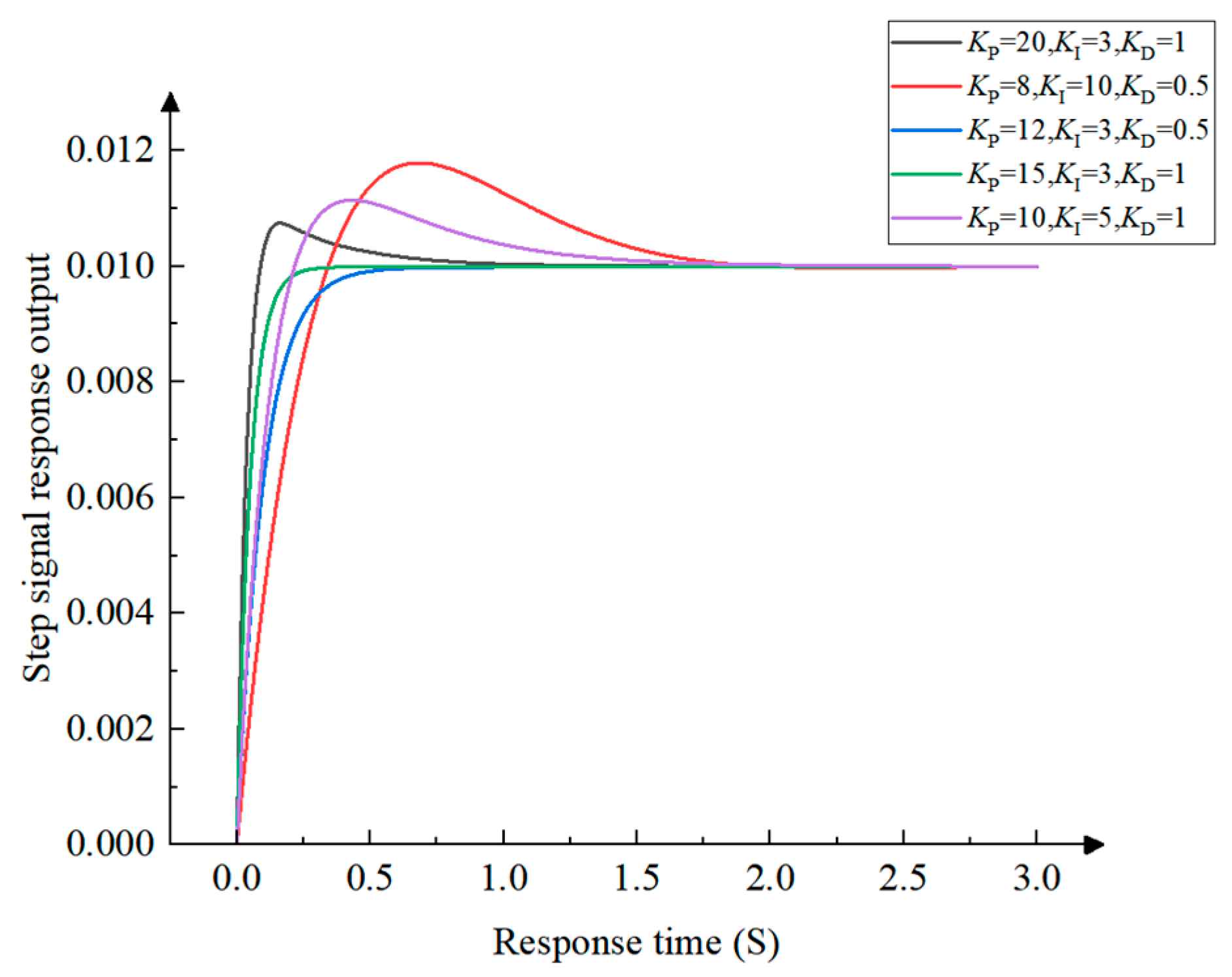
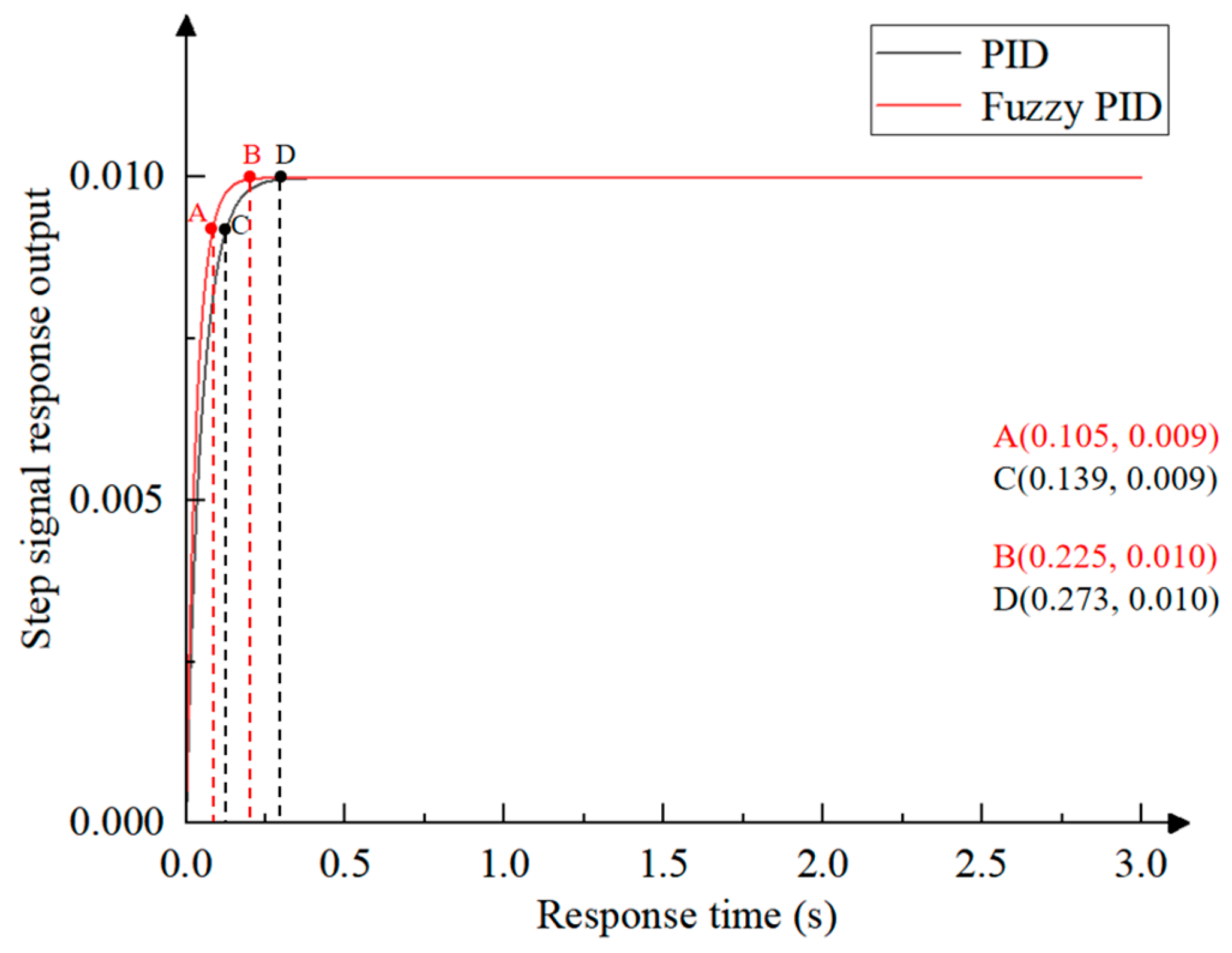
3.4.4. Modeling and Simulation Analysis of the Seedling Picking and Throwing Positioning PID Control System

The Simulink simulation module in MATLAB2024a is used to build a seedling picking and throwing positioning PID control system simulation model, as shown in Figure 15.
At t = 0, the unit step function signal is input into the control system, and the simulation time is 3 s. The three parameter values of KP, KI, and KD are adjusted. The step signal response curve of the control system is simulated, and the best parameter combination is selected. The simulation results are shown in Figure 16.
The KP, KI, and KD values of the seedling picking and throwing positioning PID control system are adjusted by empirical trial and error. As shown in Figure 14, a KP value that is too large can improve the response speed but will cause overshoot of the seedling picking and throwing positioning PID control system, while a KP value that is too small will cause the response to become slower; a KI value that is too large will cause the output signal of the seedling picking and throwing positioning PID control system to oscillate and fail to reach a steady state in a short time, while a KI value that is too small will cause the steady-state error to exist for a long time; a KD value that is too large will cause a fast response speed but will cause the output signal of the seedling picking and throwing positioning PID control system to oscillate at a high frequency or even reverse overshoot, while a KD value that is too small will cause the response speed to become slower. Therefore, the best parameter combination for the step output signal curve is KP = 15, KI = 3, and KD = 1.

3.4.5. Modeling and Simulation Analysis of the Seedling Picking and Throwing Positioning Fuzzy PID Control System

The proportional factors KE = 3/20, KEC = 3/50, K1 = 20, K2 = 10, and K3 = 2 are input to the established Simulink model of the PID control system, and the designed fuzzy controller is connected to it. The simulation model of the seedling picking and throwing positioning fuzzy PID control system is constructed, as shown in Figure 17.
At t = 0, the unit step function signal is input into the control system. The simulation time is 3 s. The simulation results of the seedling picking and throwing positioning fuzzy PID control system are shown in Figure 18.
As shown in Figure 16, the step response signals of the fixed-parameter PID control system and the fuzzy PID control system complete the rapid rise process at 0.139 s and 0.105 s, respectively, as shown in points A and C; the step response signals of the fixed-parameter PID control system and the fuzzy PID control system complete the transition to steady state at 0.225 s and 0.273 s, respectively, as shown in points B and D. Compared with the fixed-parameter PID control system, the dynamic performance of the fuzzy PID control system is significantly improved: the time consumption in the rising stage is reduced by 24.5%, and the overall stabilization process is shortened by 17.6%. The fuzzy PID control system has both the characteristics of fast response and the characteristics of zero overshoot, which provides an effective guarantee for the realization of high-precision seedling picking and throwing positioning control.

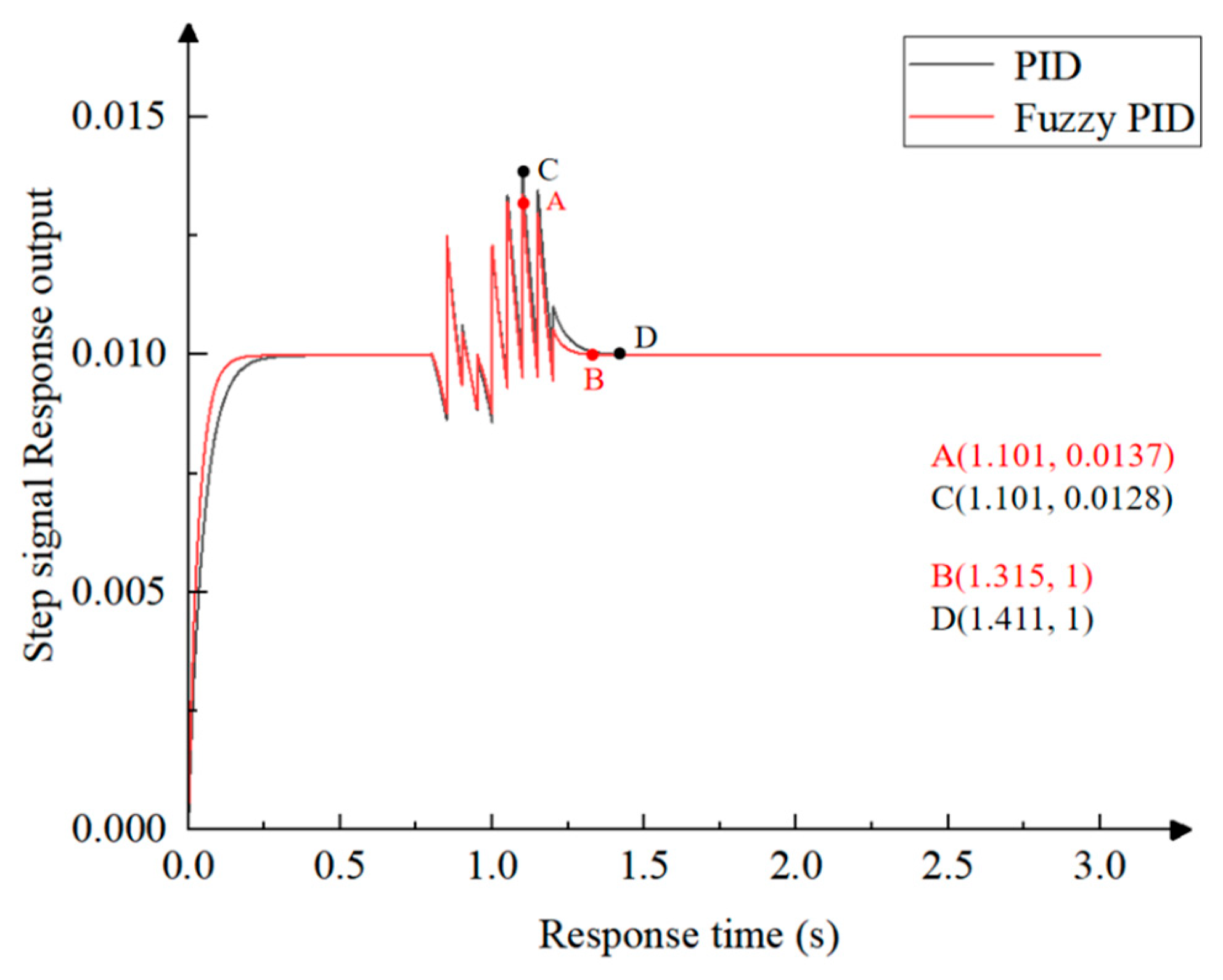
3.4.6. Modeling and Simulation Analysis of the Seedling Picking and Throwing Positioning Control System Under Disturbance Signal Conditions

Since the field operation environment has strong interference characteristics, the SPM will be disturbed by the environment in actual work, causing the control system to become unstable. Therefore, a disturbance signal is added to the unit step signal, and the PID control system with the best combination of parameters and the fuzzy PID control system are simulated in Simulink. The simulation model is shown in Figure 19.
At t = 0, a unit step function signal is input into the control system, and the simulation time is 3 s. At t = 0.8 s, a sawtooth interference signal output by the signal generator is added, with an amplitude of 0.2 and a frequency of 10 Hz, and is eliminated at t = 1.2 s. The simulation results are shown in Figure 20.
As shown in Figure 18, when the disturbance signal is added at t = 0.8 s, the two curves begin to fluctuate. The maximum values of the step response signals of the fixed-parameter PID control system and the fuzzy PID control system are 0.0137 and 0.0128, respectively, and the overshoot is 37% and 28%, respectively, as shown in points A and C. The overshoot of the fuzzy PID control system is 2.4% lower than that of the fixed-parameter PID control system. When the disturbance signal is eliminated at 1.2 s, the time for the step response signals of the fixed-parameter PID control system and the fuzzy PID control system to reach steady state is 1.411 s and 1.3151 s, respectively, as shown in points B and D. The response speed of the fuzzy PID control system is 6.8% higher than that of the fixed-parameter PID control system. The dynamic response rate and anti-disturbance performance of the fuzzy PID control system are significantly better than those of the fixed-parameter PID control system, and can better meet the requirements of the SPM in actual work.

4. Test and Result Analysis

4.1. The Bench Test of Acceleration and Deceleration Motion Control of the Seedling Picking Mechanism

4.1.1. Test Design and Evaluation Indicators

In order to verify the rationality of the SPM acceleration and deceleration motion control, a bench test of the SPM acceleration and deceleration motion control was carried out in the Agricultural Equipment and Technology Laboratory of Jiangsu University on 16 April 2025. The planned S-curve acceleration and deceleration motion control algorithm and the common trapezoidal acceleration and deceleration motion control method were loaded into the PLC of the test bench, respectively, and the feedback mechanism of the encoder was combined with the fuzzy PID control algorithm to correct the error between the actual feedback value and the theoretical value so that the motion law of the motor at each moment conforms to the used acceleration and deceleration motion control algorithm.
Four trays of 128-hole seedlings of Shanghai Bok Choy were selected as the test objects. The seedling age was 35 days, and the pot moisture content ranged from 60% to 65%. The seedling weight loss rate was used to evaluate the stability of the SPM motion process. A tray of seedlings required 16 seedling picking actions. A high-speed camera was used to count the total time Ts for picking seedlings from a whole tray of seedlings under the two motion control algorithms to verify the stability and seedling picking efficiency of the S-curve acceleration and deceleration motion control method, as shown in Figure 21. Seedling weight loss rate ηs calculation formula:
η S = M S M Z × 100 % M S = M Z M h
where ηs is the weight loss rate, 100%; Ms is the weight lost by the seedlings, g; Mz is the total weight of the seedlings before picking, g; Mh is the total weight of the seedlings after picking, g.

4.1.2. Test Results Analysis

It can be seen from Table 3 and Table 4 that when the S-curve acceleration and deceleration motion control and trapezoidal acceleration and deceleration motion control are used, the maximum ηs is 4.37% and 7.82%, the minimum ηs is 3.52% and 6.62%, and the average ηs is 3.88% and 7.21, respectively. Compared with the trapezoidal acceleration and deceleration motion control, the S-curve acceleration and deceleration motion control system reduces ηs by 46.19%. The whole seedling picking and throwing process was recorded using a high-speed camera and then compared frame by frame to record the total time Ts of the seedling picking and throwing operation corresponding to a tray of seedlings. When S-curve acceleration and deceleration motion control is used, the average total time for seedling transportation is 39.50 s, and the seedling picking efficiency is 24 plants/row/min. When trapezoidal acceleration and deceleration motion control is used, the average total time for seedling transportation is 36.46 s, and the seedling picking efficiency is 26 plants/row/min. The total running time in the bench test is slightly increased compared with the simulation test because the friction and feedback delay between the transmission mechanism are ignored in the simulation. The overall results are consistent with the simulation results, which verify the stability of the S-curve acceleration and deceleration motion control and meet the design requirements of seedling picking efficiency.

4.2. The Bench Test of the Positioning Control of Seedling Picking Mechanism

4.2.1. Test Design and Evaluation Indicators

In order to verify the accuracy of the SPM positioning control system, a bench test of SPM positioning control was carried out in the Agricultural Equipment and Technology Laboratory of Jiangsu University on 6 May 2025. Under the conditions of the planned S-curve acceleration and deceleration motion control, the fixed-parameter PID positioning control algorithm and the fuzzy PID positioning control algorithm were written into the PLC of the bench, respectively, and the positioning accuracy of SPEE under different positioning control algorithm conditions was compared. By editing the PLC program, the seedling picking action and seedling throwing action were performed step by step, which was convenient for measuring the displacement value. The seedling throwing position was taken as the initial position. In the X-axis direction, since the seedling tray was fixed, the scale was placed on one side of the seedling tray as the measurement reference. The difference between the center position of the hole and the center position of the clamping needle was measured using a 10-division vernier caliper. The maximum allowable error for a single time was ±2 mm. The average seedling picking frequency of the experimental stand was 24 plants/row/min. The displacement of 16 picked seedlings in a tray of seedlings was measured and analyzed, as shown in Figure 22.
Displacement error Ex and relative displacement error Er are used as evaluation indicators for the positioning control bench test.
E x = X X 0
E r = E x X 0 × 100 %
where X is the actual displacement of the end effector in the X-axis direction, mm; X0 is the theoretical displacement of the end effector in the X-axis direction, mm; Ex is the displacement error, mm; Er is the relative displacement error, %.

4.2.2. Test Results Analysis

By comparing and analyzing the test data in Table 5 and Table 6, using the fixed-parameter PID positioning control, the maximum displacement error of SPEE is −2.9 mm, and the average relative error rate is 0.36%, which cannot meet the positioning accuracy requirement of SPEE in the X-axis direction; using fuzzy PID positioning control, the maximum displacement error of SPEE is −1.4 mm, and the average relative error rate is 0.22%, which meets the positioning accuracy requirement of SPEE in the X-axis direction, verifying the positioning accuracy of the fuzzy PID positioning control algorithm.

4.3. The Field Test of the Motion Control System of the Seedling Picking Mechanism

4.3.1. Test Design and Evaluation Indicators

In order to test the performance of the seedling picking mechanism control system in actual operation, a field test was conducted at the Shanghai Shixin Vegetable Planting Professional Cooperative on 28 May 2025. This test used 8 trays of 128 holes of Shanghai bok choy seedlings as the test objects. The seedling age was 32 days, and the pot moisture content range was 60–65%. The planting row spacing was 120 mm, the planting plant spacing was 150 mm, and the operating speed of the transplanter was set to 0.207 km/h. The experiment was conducted with an average seedling picking frequency of 24 plants/row/min, and the test data were analyzed, as shown in Figure 23.
The success rate of seedling picking Sp, the success rate of seedling throwing St, the seedling damage rate Sl, and the comprehensive success rate of seedling picking and throwing S were selected as the test evaluation indicators, and their expressions are as follows:
S p = N 1 N × 100 %
S t = N 2 N 1 × 100 %
S l = N 3 N 1 × 100 %
S = N 2 N × 100 %
where N1 is the number of successfully picked seedlings, plants; N2 is the number of successfully thrown seedlings, plants; N3 is the number of damaged seedlings (seedlings with a weight loss of more than half), plants; N is the number of seedlings in the seedling tray, plants.

4.3.2. Test Results Analysis

Analyzing the test results in Table 7, in the field test of the seedling picking mechanism motion control system, the average Sp was 97.6%, the maximum number of damaged seedlings was 3, the average Sl was 1.3%, the average St was 98.6%, and the average S was 96.2%. This shows that the designed whole-row reciprocating seedling picking mechanism motion control system can still work stably in the field environment with interference, showing strong anti-interference ability and operation reliability, thus achieving the design purpose in terms of feasibility and practicality.

4.4. Discussion

Agricultural transplanting equipment faces complex operating environments (such as uneven soil, variable seedling morphology, and limited movement space), large system disturbances, and diversified control targets (such as positioning accuracy, flexible contact, and motion stability) during operation, which are significantly different from traditional industrial control objects. This study combines S-curve planning with fuzzy PID control to meet the requirements of smooth movement and precise positioning control of the “spm”. While achieving soft start-up and reducing impact, fuzzy control is used to improve the system’s adaptability to nonlinear disturbances and model uncertainties. Compared with traditional fixed PID control or S-curve trajectory control, this method is more in line with the comprehensive requirements of agricultural equipment for stability, rapid response, and robustness in field operations. Therefore, although the control method itself has been widely used, its system integration and optimization, combined with specific mechanical structures and control targets in agricultural transplanting equipment, still have obvious industry specificity and technical innovation.
At present, the research on the control system of the whole-row SPM is mainly aimed at realizing the automation of the operation process, and there is a lack of in-depth research on improving the motion accuracy and motion stability of the SPM from the perspective of the control algorithm [20,22]. Compared with the above research, our research focuses on motion accuracy and motion stability and effectively solves the problems of unstable operation and poor positioning accuracy of the whole-row SPM from the perspective of the control system design, effectively reducing the seedling weight loss rate and improving positioning accuracy and the overall success rate of seedling picking. This study can provide a reference for the design of the motion control system of the whole-row SPM of the transplanter. In the future, research work can be further expanded to the following aspects: introducing intelligent optimization algorithms to achieve adaptive adjustment of fuzzy PID parameters and improve the adaptability of the system to different operating conditions; strengthening software and hardware integration to promote efficient deployment of control systems on embedded platforms; and conducting more extensive test verification in complex field environments to further improve the robustness and practicality of control systems. In-depth exploration of these directions will provide strong support for the intelligent and engineering applications of agricultural equipment.

5. Conclusions

This paper focuses on the motion control problem of the whole-row reciprocating automatic SPM, and it also designs and verifies a control system based on the S-curve acceleration and deceleration and fuzzy PID composite strategy. The research results show the following:
  • Control system design and implementation: A motion control system based on PLC and stepper motor is constructed, and a composite control strategy of six-segment/seven-segment S-curve acceleration and deceleration and fuzzy PID based on planning is proposed to achieve rapid response, precise positioning, and smooth operation of the SPM.
  • Simulation verification results: MATLAB/Simulink simulation shows that S-curve motion is smoother than trapezoidal control in dynamic displacement operations, and the seedling picking efficiency is 25 plants/row/min and 27 plants/row/min, respectively, which meets the design requirements. Compared with the fixed PID control system, the fuzzy PID control system has a faster response (the rise time is shortened by 24.5%, and the overall stable process is shortened by 17.6%), and has stronger anti-disturbance (the overshoot under disturbance is reduced by 2.4%, and the response speed is increased by 6.8%).
  • Test verification results: The bench test shows that the seedling weight loss rate is reduced by 46.19% under the S-curve control, and the seedling picking efficiency is 24 plants/row/min, which meets the design requirements. The maximum displacement error of fuzzy PID control is −1.4 mm, and the average relative error rate is 0.22%, which is better than the fixed-parameter PID control. In the field test, the system’s comprehensive seedling picking success rate reached 96.2%, which verifies the robustness and practicality of the control system in an interference environment.
In summary, the proposed control strategy has good motion stability, positioning accuracy, and environmental adaptability, which can provide an effective reference for the design of motion control systems for the whole-row SPM in automatic transplanting equipment.

Supplementary Materials

The following supporting information can be downloaded at: https://www.mdpi.com/article/10.3390/agriculture15131423/s1, Video S1: Operation video of the machine.

Author Contributions

Conceptualization, J.S. and J.H.; methodology, J.S., J.H. and J.L.; software, J.S. and C.W.; validation, J.S. and W.L.; formal analysis, J.S., Y.J. and M.Y.; investigation, J.S. and Y.J.; resources, J.H.; data curation and J.L. and W.L.; writing—original draft preparation, J.S.; writing—review and editing, J.S., J.H. and W.L. All authors have read and agreed to the published version of the manuscript.

Funding

This work was supported by Development of Key Technologies and Equipment for Efficient Automatic Transplanting of Open-Field Cabbage (NJ2024-04), Special Project for the Central Government to Guide Local Science and Technology Development-Research and Development of Key Technologies and Equipment for Intelligent and Efficient Mechanized Transplanting of Watermelons, Special Project for the Integrated Pilot Project of Agricultural Machinery Research and Development, Manufacturing, Promotion and Application-Research and Development and Application of Fully Automatic, Precise and Efficient Transplanting Machine for Greenhouse Strawberries (JSYTH09), China Postdoctoral Science Foundation (2024M751185), Natural Science Foundation of Jiangsu Province (Grant No. BK20240882).

Institutional Review Board Statement

Not applicable.

Data Availability Statement

The original contributions presented in this study are included in the article/Supplementary Materials. Further inquiries can be directed to the corresponding author.

Conflicts of Interest

The authors declare no conflicts of interest.

References

  1. Periasamy, V.; Gounder, D.V.M.; Ramasamy, K. Factors influencing the performance of mechanical end effector during automatic transplanting of tomato seedlings. J. Appl. Nat. Sci. 2022, 14, 227. [Google Scholar] [CrossRef]
  2. Wu, G.; Wang, S.; Zhang, A.; Xiao, Y.; Li, L.; Yin, Y.; Li, H.; Wen, C.; Yan, B. Optimized design and experiment of a self-covering furrow opener for an automatic sweet potato seedling transplanting machine. Sustainability 2023, 15, 13091. [Google Scholar] [CrossRef]
  3. Xu, X.; Zhou, M.; Chen, X.; Yang, J. Processing method of gearbox with non-circular gear train and its application in rice potted seedling transplanting mechanism. Agriculture 2022, 12, 1676. [Google Scholar] [CrossRef]
  4. Sharma, A.; Khar, S. Design and development of a vegetable plug seedling transplanting mechanism for a semi-automatic transplanter. Sci. Hortic. 2024, 326, 112773. [Google Scholar] [CrossRef]
  5. Han, L.; Mo, M.; Ma, H.; Kumi, F.; Mao, H. Design and test of a lateral-approaching and horizontal-pushing transplanting manipulator for greenhouse seedlings. Appl. Eng. Agric. 2023, 39, 325–338. [Google Scholar] [CrossRef]
  6. Yin, J.; Wang, Z.; Zhou, M.; Wu, L.; Zhang, Y. Optimized design and experiment of the three-arm transplanting mechanism for rice potted seedlings. Int. J. Agric. Biol. Eng. 2021, 14, 56–62. [Google Scholar] [CrossRef]
  7. Miah, M.S.; Rahman, M.M.; Hoque, M.A.; Ibrahim, S.M.; Sultan, M.; Shamshiri, R.R.; Ucgul, M.; Hasan, M.; Barna, T.N. Design and evaluation of a power tiller vegetable seedling transplanter with dibbler and furrow type. Heliyon 2023, 9, e17827. [Google Scholar] [CrossRef]
  8. Zhou, M.; Shan, Y.; Xue, X.; Yin, D. Theoretical analysis and development of a mechanism with punching device for transplanting potted vegetable seedlings. Int. J. Agric. Biol. Eng. 2020, 13, 85–92. [Google Scholar] [CrossRef]
  9. Han, L.; Mo, M.; Gao, Y.; Ma, H.; Xiang, D.; Ma, G.; Mao, H. Effects of new compounds into substrates on seedling qualities for efficient transplanting. Agronomy 2022, 12, 983. [Google Scholar] [CrossRef]
  10. Pérez-Ruiz, M.; Slaughter, D.C. Development of a precision 3-row synchronised transplanter. Biosyst. Eng. 2021, 206, 67–78. [Google Scholar] [CrossRef]
  11. Jorg, O.J.; Sportelli, M.; Fontanelli, M.; Frasconi, C.; Raffaelli, M.; Fantoni, G. Design, development and testing of feeding grippers for vegetable plug transplanters. AgriEngineering 2021, 3, 669–680. [Google Scholar] [CrossRef]
  12. Khadatkar, A.; Mathur, S. Design and development of an automatic vegetable transplanter using a novel rotating finger device with push-type mechanism for plug seedlings. Int. J. Veg. Sci. 2022, 28, 121–131. [Google Scholar] [CrossRef]
  13. Zhao, S.; Liu, J.; Jin, Y.; Bai, Z.; Liu, J.; Zhou, X. Design and testing of an intelligent multi-functional seedling transplanting system. Agronomy 2022, 12, 2683. [Google Scholar] [CrossRef]
  14. Zhou, M.; Wei, Z.; Wang, Z.; Sun, H.; Wang, G.; Yin, J. Design and experimental investigation of a transplanting mechanism for super rice pot seedlings. Agriculture 2023, 13, 1920. [Google Scholar] [CrossRef]
  15. Yu, G.; Wang, L.; Sun, L.; Zhao, X.; Ye, B. Advancement of mechanized transplanting technology and equipments for field crops. Nongye Jixie Xuebao/Trans. Chin. Soc. Agric. Mach. 2022, 53, 1–20. [Google Scholar]
  16. Jin, Y.; Liu, J.; Xu, Z.; Yuan, S.; Li, P.; Wang, J. Development status and trend of agricultural robot technology. Int. J. Agric. Biol. Eng. 2021, 14, 1–19. [Google Scholar] [CrossRef]
  17. Ji, J.; Cheng, Q.; Jin, X.; Zhang, Z.; Xie, X.; Li, M. Design and test of 2ZLX-2 transplanting machine for oil peony. Int. J. Agric. Biol. Eng. 2020, 13, 61–69. [Google Scholar] [CrossRef]
  18. Liao, Q.; Wang, Y.; Hu, Q.; Zhang, Q.; He, K.; Xiao, W. Design and experiment on pick-up device for rapeseed substrate seedling transplanter. Nongye Jixie Xuebao/Trans. Chin. Soc. Agric. Mach. 2020, 51, 93–102. [Google Scholar]
  19. He, Y.; Yan, H.; Cui, W.; Chen, K.; Han, Z.; Bao, C. Research Situation and Analysis on Automatic Transplanting Technology for Vegetable Seedling. Agric. Eng. 2018, 8, 1–7. [Google Scholar]
  20. Wei, X.; Bao, S.; Liu, X.; Liu, C.; Mao, H. Design and experiment on potted-seedling automatic transplanter control system for motion coordinating. Nongye Jixie Xuebao/Trans. Chin. Soc. Agric. Mach. 2016, 47, 1–7. [Google Scholar]
  21. Han, C.; Zhou, T.; You, J.; Xu, Y.; Mao, H.; Liang, J. Design and experiments of an arc expansion type automatic seedling taking and throwing device for vegetable plug seedlings. Trans. Chin. Soc. Agric. Eng. 2023, 39, 54–64. [Google Scholar]
  22. Hu, J.; Chang, H.; Yang, L.; Han, L.; Mao, H.; Zhang, S. Design and experiment of control system for automatic transplanter picking up and spacing casting whole row of seedlings. Nongye Jixie Xuebao/Trans. Chin. Soc. Agric. Mach. 2018, 49, 78–84. [Google Scholar]
  23. Liu, J.; Cao, W.; Xu, H.; Tian, D.; Jiao, H.; Ouyang, Y. Adaptive fuzzy-PID control of accurate orientation for auto-detect seedling supply device. Trans. Chin. Soc. Agric. Eng. 2017, 33, 37–44. [Google Scholar]
  24. Kong, D.; Zhang, X.; Cui, W.; Wu, H.; Sun, X.; Wang, Z.; Wang, C.; Ning, Y. Control Method for Seedling Tray Positioning in Top-clamping Seedling-taking Device Based on Fuzzy PID. Trans. Chin. Soc. Agric. Mach. 2024, 55, 207–216+229. [Google Scholar]
  25. Wrat, G.; Bhola, M.; Ranjan, P.; Mishra, S.K.; Das, J. Energy saving and Fuzzy-PID position control of electro-hydraulic system by leakage compensation through proportional flow control valve. ISA Trans. 2020, 101, 269–280. [Google Scholar] [CrossRef]
  26. Kombarov, V.; Sorokin, V.; Fojtů, O.; Aksonov, Y.; Kryzhyvets, Y. S-curve algorithm of acceleration/deceleration with smoothly-limited jerk in high-speed equipment control tasks. MM Sci. J. 2019, 2019, 3264–3270. [Google Scholar] [CrossRef]
  27. Gai, R.; Guo, Y. Research on acceleration and deceleration control algorithm of S-curve. In Proceedings of the 2021 IEEE 23rd Int Conf on High Performance Computing & Communications; 7th Int Conf on Data Science & Systems; 19th Int Conf on Smart City; 7th Int Conf on Dependability in Sensor, Cloud & Big Data Systems & Application (HPCC/DSS/SmartCity/DependSys), Haikou, China, 20–22 December 2021; pp. 2104–2110. [Google Scholar]
  28. Jin, X.; Liu, J.; Chen, Z.; Xu, Z.; Ji, J. Precision control system of rice potting and transplanting machine based on GA-Fuzzy PID controller. Comput. Electron. Agric. 2024, 220, 108912. [Google Scholar] [CrossRef]
  29. Jin, X.; Chen, K.; Zhao, Y.; Ji, J.; Jing, P. Simulation of hydraulic transplanting robot control system based on fuzzy PID controller. Measurement 2020, 164, 108023. [Google Scholar] [CrossRef]
Figure 1. The research scheme.
Agriculture 15 01423 g001
Figure 2. A schematic diagram of the seedling picking system structure: 1. seedling tray conveying mechanism; 2. seedling separating mechanism; 3. seedling picking mechanism; 4. 128-hole seedling tray.
Agriculture 15 01423 g002
Figure 3. A structural diagram of the seedling picking mechanism: 1. X-axis zero position sensor; 2. Z-axis zero position sensor; 3. moving fixed plate; 4. lead screw stepper motor (LSSM); 5. lifting cylinder; 6. lifting fixed plate; 7. end effector fixed plate; 8. driving chain; 9. X-axis guide rail slider mechanism; 10. stepper motor (SM); 11. decelerator; 12. Z-axis guide rail slider mechanism; 13. hydraulic buffer; 14. seedling picking end effector (SPEE); 15. seedling pushing ring.
Agriculture 15 01423 g003
Figure 4. A schematic diagram of the working principle of the seedling picking mechanism: (a) schematic diagram of the seedling picking steps; (b) schematic diagram of the seedling throwing steps.
Agriculture 15 01423 g004
Figure 5. A schematic diagram of seedling picking steps and the seedling tray size.
Agriculture 15 01423 g005
Figure 6. A Schematic diagram of control system hardware.
Agriculture 15 01423 g006
Figure 7. The control system interface.
Agriculture 15 01423 g007
Figure 8. The action sequence diagram of each driving mechanism.
Agriculture 15 01423 g008
Figure 9. The main program flow chart of the seedling picking and throwing control system.
Agriculture 15 01423 g009
Figure 10. A schematic diagram of speed, acceleration, and jerk of the seven-segment S-curve acceleration and deceleration algorithm.
Agriculture 15 01423 g010
Figure 11. The relationship between the speed, acceleration, and time of SPEE under the condition of six-stage S-curve acceleration and deceleration control algorithm when s = 424 mm. (a) The relationship between the speed and time; (b) the relationship between acceleration and time.
Agriculture 15 01423 g011
Figure 12. The relationship between the speed, acceleration, and time of SPEE under the condition of a seven-stage S-curve acceleration and deceleration control algorithm when s = 584 mm. (a) The relationship between the speed and time; (b) the relationship between acceleration and time.
Agriculture 15 01423 g012
Figure 13. The relationship between the speed, acceleration, and time of SPEE under the condition of trapezoidal acceleration and deceleration control algorithm when s = 584 mm. (a) The relationship between speed and time; (b) the relationship between acceleration and time.
Agriculture 15 01423 g013
Figure 14. A block diagram of the fuzzy PID seedling picking motion positioning control system.
Agriculture 15 01423 g014
Figure 15. A simulation model of a PID control system.
Agriculture 15 01423 g015
Figure 16. Simulation results of the PID control system under different parameter conditions.
Agriculture 15 01423 g016
Figure 17. The simulation model of the seedling picking and throwing positioning fuzzy PID control system.
Agriculture 15 01423 g017
Figure 18. The simulation model of a control system under the disturbance signal condition.
Agriculture 15 01423 g018
Figure 19. The simulation model of the seedling picking and throwing positioning PID control system.
Agriculture 15 01423 g019
Figure 20. Simulation results of the control system under disturbance signal conditions.
Agriculture 15 01423 g020
Figure 21. The test of the stability of the SPM motion process.
Agriculture 15 01423 g021
Figure 22. The test of the positioning accuracy of the seedling picking mechanism.
Agriculture 15 01423 g022
Figure 23. A field test of the motion control system of the seedling picking mechanism.
Agriculture 15 01423 g023
Table 1. Fuzzy PID control rules.
EEC
NBNMNSZOPSPMPB
NBPB/NB/PSPB/NB/NSPM/NM/NBPM/NM/NBPS/NS/NBZO/ZO/NMZO/ZO/PS
NMPB/NB/PSPB/NB/NSPM/NM/NBPS/NS/NMPS/NS/NMZO/ZO/NSNS/ZO/ZO
NSPM/NB/ZOPM/NM/NSPM/NS/NMPS/NS/NMZO/ZO/NSNS/PS/NSNS/PS/ZO
ZOPM/NM/ZOPM/NM/NSPS/NS/NSZO/ZO/NSNS/PS/NSNM/PM/NSNM/PM/ZO
PSPS/NM/ZOPS/NS/ZOZO/ZO/ZONS/PS/ZONS/PS/ZONM/PM/ZONM/PB/ZO
PMPS/ZO/PBZO/ZO/NSNS/PS/PSNM/PS/PSNM/PM/PSNM/PB/PSNB/PB/PB
PBZO/ZO/PBZO/ZO/PMNM/PS/PMNM/PM/PMNM/PM/PSNB/PB/PSNB/PB/PB
Table 2. Motor parameters.
ModuleStep Angle/°Rated Current/AStatic Torque/N·mResistance/ΩInductance/mHRotor Inertia/kg·cm2Back EMF CoefficientNumber of Rotor TeethWeight/kgDamping Coefficient
57CME261.852.60.442.00.520.15500.70.008
Table 3. Test results of seedling weight loss rate under the S-curve acceleration and deceleration control conditions.
TypesNumberMz (g)Mh (g)Ms (g)ηs (%)Ts (s)
S-curve11675.621602.4673.164.3739.24
21692.201632.6259.583.5239.66
31710.741648.4362.313.6439.42
41679.131612.3166.823.9839.68
average value 3.8839.50
Table 4. Test results of the seedling weight loss rate under trapezoidal acceleration and deceleration control conditions.
TypesNumberMz (g)Mh (g)Ms (g)ηs (%)Ts (s)
Trapezoid11623.881516.26107.626.6236.96
21682.411568.18114.237.2836.22
31631.571503.89127.687.8236.24
41667.941549.54118.407.1036.43
average value 7.2136.46
Table 5. Test results of the positioning error of the fixed-parameter PID positioning control system.
NumberX0 (mm)X (mm)Ex (mm)Er (%)
1360358.2−1.80.50
2360357.1−2.90.81
3392389.6−2.40.61
4392390.7−1.30.33
5424425.21.20.28
6424422.3−1.70.40
7456457.11.10.24
8456454.8−1.20.26
9488490.32.30.47
10488489.71.70.35
11520521.61.60.13
12520521.21.20.23
13552550.9−1.10.20
14552553.71.70.31
15584582.4−1.60.27
16584582.3−1.70.29
Table 6. Test results of the positioning error of the fuzzy PID positioning control system.
NumberX0 (mm)X (mm)Ex (mm)Er (%)
1360358.6−1.40.39
2360358.2−0.80.22
3392389.7−1.30.33
4392391.1−0.90.23
5424426.21.20.28
6424424.40.40.09
7456454.6−1.40.31
8456454.9−1.10.24
9488488.50.50.11
10488489.31.30.27
11520518.6−1.40.27
12520519.1−0.90.17
13552551.3−0.70.13
14552550.9−1.10.20
15584582.8−1.20.21
16584583.3−0.70.12
Table 7. T Field test results.
NumberN (Plants)N1 (Plants)Sp
(%)
N3
(Plant)
Sl (Plant)N2 (Plant)St
(%)
S
(%)
112812597.721.612510097.7
212812698.40012397.696.1
312812496.932.412298.495.3
412812597.721.612499.296.9
512812597.710.812499.296.9
612812496.921.612197.694.5
712812698.410.812498.496.9
812812496.921.612298.495.3
average 97.6 1.3 98.696.2
Disclaimer/Publisher’s Note: The statements, opinions and data contained in all publications are solely those of the individual author(s) and contributor(s) and not of MDPI and/or the editor(s). MDPI and/or the editor(s) disclaim responsibility for any injury to people or property resulting from any ideas, methods, instructions or products referred to in the content.

