Abstract
Ridge-breaking earth cultivation is a new agronomic technology that simplifies and efficiently cultivates ratoon sugarcane. However, traditional cultivators cannot adapt to the distribution of residual stumps, inter-row specifications, and hardened clay soil. This results in substandard soil fragmentation, poor ridge quality, and reduced operational reliability. To address these issues, this article proposes an integrated earth cultivator structure capable of breaking ridges, loosening soil, and raising ridges simultaneously. It is designed to enhance the breaking of tillage layers and the filling of ridges through the coordinated action of multiple soil-engaging components. The effects of pre-loosening by the ridge-breaking plow, high-energy crushing, and throwing by the spirally arranged dense rotary blade group, and soil gathering by the deflector are comprehensively utilized. Additionally, lateral pushing by the ridging plough is employed. Discrete element and finite element simulation results show that densely toothed blades can improve soil supply capacity and structural reliability. This is achieved by increasing the amount of soil throwback and reducing concentrated stress levels. Soil fragmentation rate (SFR) and ridge height (RH) were further used as indicators. Field experiments were conducted to study the effects of operating parameters on breaking and ridging performance. The optimal parameter solution was determined as a forward speed of 0.85 m·s−1 and rotary speed of 289.7 r·min−1. With this adaptive configuration, SFR and RH were improved by 12.4% and 38.5%, respectively, compared with conventional earth cultivators. Additionally, the RSM value of rotary tillage power (Pr) was reduced by 39.6%. Improvements in crushing hardened fields, constructing ridges, and reducing cutting energy consumption have proven effective. This study can provide a reference for the development of earth cultivators based on new agronomy and specific field characteristics.
1. Introduction
Sugarcane is a perennial ratoon crop. In Guangxi Province, the main sugarcane-producing area in China, cultivation mostly follows a circular planting model. In this model, new planting is implemented in the first year. Over the following 2–4 years, the sugarcane stumps remaining in the field after harvest are reused for new sprout growth. Therefore, annual field management of ratoon sugarcane is crucial, with earth cultivation being a key component. The cultivated ridges can increase the depth of root system into the soil and reduce the lodging of tall stems. As a result, root growth is promoted, ineffective tillering is inhibited, and the yield of ratoon sugarcane is enhanced [1,2]. Recently, efforts have focused on reducing the compound costs of various field management operations while improving planting quality. Based on the technological requirements for simple and efficient sugarcane cultivation, the operating procedures for ratoon cane cultivation were reintegrated. A combined agronomic method for ratoon cane fields was proposed, which could accomplish ridge-breaking, loosening, fertilization, and earth cultivation in one go [3]. This new agronomic method eliminates the need for fertilization and tillage during subsequent seedling growth, allowing for a more concentrated and compact farming schedule. Additionally, it offers advantages such as reduced risks of drought, rot diseases, and frostbite caused by exposed ratoon stumps. Heat preservation, anti-freeze measures, and water retention aim to promote the germination and root development of low-position buds [4,5]. This further reduces the problem of pulling out cane stumps during mechanical harvesting. In terms of the timing of agronomic implementation, ridge-breaking earth cultivation is generally scheduled after chopping leaves and cutting stubble. Therefore, the cultivated soil should fully cover the heads of the originally exposed cane stumps. This means that a certain thickness of soil coverage is required for effective filling.
However, in Guangxi, which is located in the northern hemisphere, ridge-breaking earth cultivation operations are typically conducted during winter. During this time, the climate is dry due to lack of rain. Additionally, repeated crushing by harvesters and tractor tires has caused the cultivated soil to become significantly hard and sticky. Under such conditions, the compacted tillage layer and agglomerated soil particles require the ridge-breaking earth cultivator to face higher cutting and pushing loads. This can easily lead to structural damage and inadequate soil crushing of the welded blade holder or installed rotary tiller, significantly affecting operational reliability. It is also worth noting that the germination of ratoon stumps is also hindered under the coverage of larger particles. On the other hand, most sugarcane cultivation currently adopts a wide row spacing pattern of 1.2–1.4 m. The ridge formation mainly depends on a plow with double wings to squeeze and push the soil from the furrow to the ridges on both sides [6]. However, in ratoon fields, the cultivating plow’s lateral working width must avoid the center of stumps to prevent damaging the tillers due to the wide distribution of cane roots. This contradiction between the smaller working width and wider target row spacing can easily lead to insufficient lateral movement distance of pushed soil particles. As a result, the desired ridging position is often not achieved. Insufficient transport of soil material usually causes a certain degree of depression in the middle of ridges built between the two plows. This results in cane stumps that should be buried not being fully covered. Such ridges will then be washed away by rainwater for about a year, resulting in increased soil loss, as the depression makes rainwater drainage difficult. The more serious lack of soil at the base of the stem causes the ridge to increasingly resemble a “crater.” This problem of soil cultivation quality will reduce the depth of root penetration into the soil and affect the growth height of crops. The lack of mechanical support at the bottom often leads to stem lodging, which causes harvesters to cut at a higher position and consequently reduces yield. At the same time, the increase in stubble damage and the induction of high-position buds will also reduce the effective number of ratoon stump shoots sprouting in the coming year [7,8].
In the study of hilly machinery that combines different crops and their agronomic characteristics, Lv et al. [9] developed a potato cultivator suitable for a row spacing of 1.2 m. This machine is capable of increasing soil breakage rate and weeding, fertilizing, and cultivating soil simultaneously. Kudzaev et al. [10] proposed an earth cultivator with closed-loop elastic suspension to reduce the forward working resistance under stony soil conditions and improve the reliability of working depth. Using full-film and double ridge–furrow sowing technology, Zhang et al. [11] developed a tiller for loosening soil, weeding, and raising ridges before crop growth. This tiller can be adjusted to meet the requirements of different ridge widths and heights. In order to solve the problems of poor ridge quality and difficult-to-control shape, Zhang et al. [12] proposed a spiral composite tobacco cultivator that can realize upward transportation of soil and control of the ridge shape. In addition, Yuttana et al. [13] designed a tractor-pulled inter-row shredder for loosening and crushing soil during cultivation at the seedling stage. Liu et al. [14] developed a diamond-shaped, four-wheel sugarcane fertilizing and cultivating machine. With its large ground clearance, this machine is suitable for earth cultivation during the sugarcane seedling jointing stage, thereby extending the window period for intertillage operations. In summary, existing soil cultivation tools are mainly aimed at traditional soil loosening and ridging agronomy [15]. However, given the working conditions of ratoon cane fields and the new agronomic adaptability requirements for ridge-breaking earth cultivation, suitable mechanical operation methods are lacking. These methods should combine ridge breaking, loosening, and soil–leaf–fertilizer mixing effectively.
In the research on soil-engaging components for soil cultivation, Gürsoy et al. [16] studied the effects of different operating speeds and plow widths on ridge quality by measuring soil throwing distance, disturbance width, and ridge height. Bulgakov et al. [17] explored the influence of cultivating plow surface parameters and soil motion state on dynamic resistance to improve the resistance characteristics of the moldboard. Mudarisov et al. [18] used the rheological model of Newtonian viscous fluid to model the soil tillage process and thus provide a predictive reference for analyzing soil flow. Cheng et al. [19] used the discrete element simulation method (DEM) to explore the influence of factors. These factors include rotation speed and feed speed of the potato cultivator blades on the soil breakage rate and soil throwing mass distribution. Tong et al. [20] proposed a spiral blade set and analyzed the movement state of the soil and optimal working parameter combination under the expected shaping effect. However, the design of the above-mentioned components lacks cooperation among integrated collaborative working functions. As a result, when dealing with compacted heavy clay soil, the comprehensive soil breaking and ridging properties still cannot meet the standards of ratoon sugarcane cultivation operations. And the ability to bury and cover sugarcane stumps needs to be improved.
Traditional split cultivators have deficiencies in terms of inter-row adaptability, soil fragmentation, ridge filling, and reliability. Considering the new agronomic specifications for ridge breaking and earth cultivation, this article proposes an integrated ridge-breaking earth cultivator. This cultivator can perform field breaking, loosening, and enhanced filling in oneoperation. Based on measured ratoon soil properties and field structure-forming requirements, the overall structure was designed to enhance crushing capacity and accommodate agronomic specifications. The working principle of soil supply–transmission–accumulation under the coordination among soil-engaging components was determined. Discrete element and finite element simulations were used to analyze how dense rotary blade groups strengthen soil supply and stress intensity. Field experiments were conducted using response surface methodology to study the effects of operating parameters on the comprehensive capabilities of ridge breaking and raising. Subsequently, performance improvements obtained using the optimal parameters were verified through multi-objective optimization. These improvements were then compared with the original operation quality. Rotary tillage power was also used to evaluate energy consumption during the cutting of compacted farmland.
2. Materials and Methods
2.1. Existing Operating Conditions
2.1.1. Ratoon Field Landscape
For a typical standardized sugarcane growing area in South China (located in Fusui County, Chongzuo City, Guangxi), mechanical harvesting is typically conducted in winter. As a follow-up step, the agronomic operations of ridge breaking–fertilizing–earth cultivation are generally scheduled in winter, that is, from December to February of the following year. This sugarcane area has a subtropical monsoon climate, with drought during this period. Moreover, the fields have been repeatedly trampled by harvesters, trucks, leaf-shredding tractors, etc., causing the previously clayey soil to gradually harden.
A multi-acre field cultivated with perennial sugarcane that has been harvested three times was selected as the geological observation sample of the work object, as shown in Figure 1. The planting row spacing in this plot was 140 cm. It can be seen that the landscape before cultivation was covered with a large number of sugarcane leaves. There are still scattered cane stumps distributed along the ridge tops, and the horizontal terrain fluctuations between ridges and furrows were no longer so obvious. In order to investigate the specificity of current soil operating conditions compared with other field attributes or seasons, the changes in soil moisture content and hardness at different tillage layer depths were measured. These measurements were taken using the multi-point sampling-drying method and a hardness meter (TYD-2 type), as shown in Figure 2.
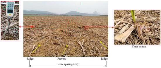
Figure 1.
Working topography of ratoon cane cultivation fields and its measurement of hardness.
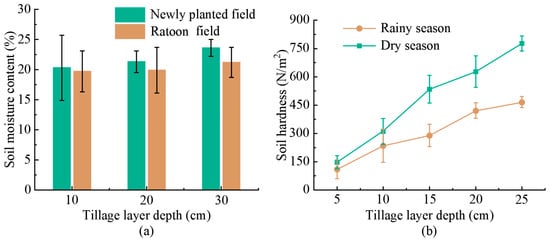
Figure 2.
Changes in soil physical properties with tillage layer depth: (a) Comparison of moisture content between different field types; (b) Comparison of hardness between different seasons.
It can be found from Figure 2a that the moisture content basically slightly increases as the tillage layer deepens. However, during ridge-breaking earth cultivation operation, the water-holding capacity of ratoon fields is significantly weaker than that of the newly planted cane fields. The reason is inferred to be related to the fact that the soil layers contain a large amount of deposited fertilizer salts and organic matter produced by returning straw to the field [21]. This results in the cultivated land being more compact and possessing certain drainage characteristics. Judging from the soil hardness traversal of ratoon cane fields in different seasons, the hardness (average value of 646.7 N/cm2) in the dry season is significantly greater than the value (392.4 N/cm2) in the rainy season. Overall, the hardness range of a ratoon field is significantly larger than that of other crops [22]. This soil texture becomes progressively compact and viscous with increasing depth. As a result, this characteristic increases the design requirements for the cultivator to break up hardened layers and agglomerated soil. Improved soil fragmentation is important for seedling emergence after ridge coverage and the filling ability with plow push.
2.1.2. Agronomic Requirements of Ridge-Breaking Earth Cultivation
In order to achieve simple and efficient cultivation, the new agronomic technology integrating ridge-breaking and earth cultivation was developed. This technology has changed the original extensive management mode of perennial ratoon sugarcane. It requires a one-time operation within one month after harvesting canes and shredding leaves. The main agronomic processes are as follows: First, as shown in Figure 3a, the compacted tillage layer in the ridge–furrow area (S1) near stumps is broken. The soil clods are then loosened and lifted while being crushed. Secondly, long-acting slow-release fertilizer is further applied and mixed with crushed soil and sugarcane leaves. Finally, the ridge body (S2) is piled up by pushing the soil sideways to cover ratoon cane heads. Taking into account agronomic practices, soil conditions, and climate in major sugarcane-producing regions, the adaptive operational requirements for the ridge-breaking earth cultivator are as follows:
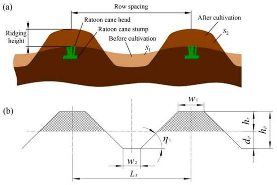
Figure 3.
Ridge–furrow alternating terrain. (a) Changes in topography before and after ridge-breaking earth cultivation operations; (b) Structured forming parameters.
- Taking the gradient terrain of ridges and furrows with a row spacing of 1.4 m as the work object, it has integrated functions of effectively performing ridge breaking and soil lifting. Additionally, it can crush, mix, and raise ridges, forming a small and intensive structure [23].
- The machine can fully loosen hardened soil and has a soil breakage rate of more than 85%. The height of covered soil reaches 15~20 cm, forming an effective filling of the ratoon cane heads [24].
Accordingly, the available geometric dimensions of ridge rows after earth cultivation are extracted and simplified, and the structured forming parameters are illustrated in Figure 3b.
2.1.3. Performance Problems of Conventional Separate Cultivators
The breaking up of soil and subsequent lateral pushing are necessary steps in most earth cultivation processes. Therefore, traditional cultivators typically use a separate design for the rotary tiller and double-wing plow to complete the above soil-contacting operations, as shown in Figure 4. However, practices in large-scale compacted cane fields have shown that the cultivated ridge quality and mechanical reliability are poor. The causes of performance problems are analyzed as follows:
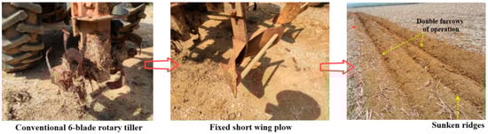
Figure 4.
The separated components of the original cultivator and the resulting sunken situation.
- The traditional rotary cutterhead features a welded-blade holder structure. Due to the limited installation space, the blade arrangement is impractical, and only 4 rotary blades are used for ridge breaking. This undoubtedly results in insufficient crushing force and cutting frequency to fully crush hard clay blocks. Moreover, excessive unit soil cutting load makes the cantilevered blade mounting structure susceptible to break and damage, further weakening the disintegration of soil.
- The destructive intensity of blades to soil is limited. Thus, the effective working depth of the rotary tiller is reduced, resulting in less soil available for ridge raising. In addition, the plowing depth of the rear cultivating plow is also limited. The combination of these reasons results in an inability to provide sufficient soil supply for covering ratoon cane.
- Under wide row spacing conditions, the fixed short-wing plow cannot adapt to terrain changes in time. Additionally, it cannot provide sufficient driving force and lateral transport displacement for heavier soil particles. The insufficient amount of soil transported to the top of cane stumps causes the center of the ridge to be sunken.
The analysis above suggests that when designing a ridge-breaking earth cultivator for ratoon sugarcane fields, the arrangement distance between components should be further reduced. The effective soil-engaging components should be more compactly and efficiently integrated, with an emphasis on enhancing their soil-crushing and soil-pushing capabilities. This approach ensures a more adequate tillage depth and soil transport volume during the cultivation process.
2.2. Overall Structure and Working Principle
In order to improve adaptability to compacted fields, the design improvements of ridge-breaking earth cultivator need to integrate agronomic operation requirements and working conditions. Based on agronomic procedures, the design goal is to enhance the effective coverage of the sugarcane stump. Using a modular cooperative design approach, the overall structural configuration is shown in Figure 5a. The ridge-breaking earth cultivator mainly consists of effective soil-engaging components and auxiliary parts. The effective soil-engaging components include the ridge-breaking front plow, dense rotary tiller, upper soil deflector, and rear ridging plough. The auxiliary parts include transmission components, positioning components, and the frame. The above primary soil-engaging components and their corresponding functional improvement relationships are illustrated in Figure 6. It is anticipated to improve the quality of soil filling in ratoon sugarcane fields by comprehensively enhancing soil fragmentation, soil lifting amount during furrowing, and ridge-forming capabilities.
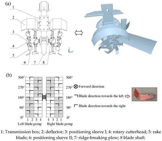
Figure 5.
Structural layout of the ridge-breaking earth cultivator. (a) Overall composition; (b) circumferential expansion of the arrangement of rotary blades.
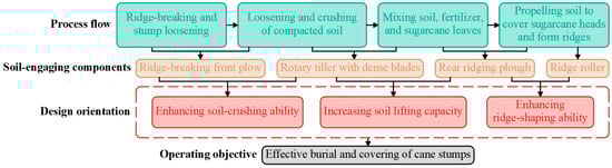
Figure 6.
Explanation of design improvement orientation for components.
The cooperative working principle of the ridge-breaking earth cultivator components can be described as follows: First, the ridge-breaking front plow (at a penetration angle of 27°) exerts concentrated stress on compacted farmland, causing tillage layers to break and achieving a pre-loosening effect. Consequently, the cutting resistance of subsequent rotary tillers is reduced and soil fragmentation is enhanced. Then, high-speed rotating dense rotary blades apply high-energy shear stress to the soil clods. The fragmented soil is thrown backwards to provide finely crushed particles for the flowing plow.
Meanwhile, the upper deflector acts to prevent soil dispersion and increase the soil supply for ridging. Subsequently, the rear ridging plough pushes the soil laterally through extrusion, forming accumulations on both sides to cover the ratoon cane stumps. Finally, the ridge roller smooths out the irregularities on ridge tops to prevent soil erosion due to settlement. In general, the soil loosening, fragmentation, and efficient transfer required for ridge-breaking earth cultivation are achieved through the coordinated action of multiple soil-engaging components. The main technical parameters involved in the machine are listed in Table 1.

Table 1.
Main technical parameters of the ridge-breaking earth cultivator.
2.3. Design of Soil-Engaging Components Based on Ridge-Breaking Soil Cultivation Agronomy
2.3.1. Dense Arrangement of Rotary Blades
In order to improve the soil-crushing ability of the rotary tiller on compacted clay and to provide sufficiently fine soil for the subsequent lateral push of the plough, a densely arranged rotary tiller configuration was designed. This configuration includes an increased number of installed blades, as shown in Figure 5a. The machine is powered by a double-row roller-chain transmission box with a sprocket center distance of 610 mm. The main components of a rotary tiller include a blade shaft, a cutterhead, rake blades, and an attached leak-proof plow and arc-shaped soil deflector. Additionally, the holes and sleeves on the shaft are used for circumferential and axial positioning, respectively. The positioning sleeves can be replaced and the number of cutterheads can be adjusted to change the tilling width, accommodating for different row spacings. Because the current standard row spacing for ratoon sugarcane is 140 cm, two cutterheads are installed on each side of the rotary shaft. Each side’s tilling range is divided into four cutting sub-areas. To improve the reliability of components, wider rake blades were used, as shown in Figure 5b. To meet the design requirements of reducing stress on individual blades while improving soil fragmentation, each cutting sub-area contains a maximum of three blades (z). As shown in Figure 5b, each side of the rotary tiller blade set includes a total of 12 rake blades, which are arranged in a staggered pattern of 6 short helical lines. The helix angles of all helices are set identically, enabling the rake blades to alternately engage the soil in different directions during operation. This configuration promotes axial pushing of the soil, increasing soil supply for lateral ridge formation. Furthermore, the gathering and upward throwing of soil particles can create favorable conditions for obtaining usable soil for subsequent ridging. A soil deflector is installed above the rotary tiller, maintaining a 150 mm gap to deflect soil clods and sugarcane leaves sideways, preventing clogging.
2.3.2. Determination of Rotary Tillage Parameters Based on Cutting Kinematics
To achieve better cutting and burying effects while minimizing torque resistance, especially when cane leaves cover the ground, the forward rotation method is used for rotary tillage [25]. The process of the blade cutting the soil involves compound motion; thus, a single blade is used as the object of kinematic analysis. Taking the forward direction of the machine as the positive x-axis, an Oxy rectangular coordinate system with the blade shaft center as the origin is established, as shown in Figure 7. The motion trajectory of the blade tip point (A) can be regarded as a mathematical cycloid composed of rotation and linear motion, and its equation can be expressed as:
where tR is movement time of blade shaft, ω is rotation angular speed, vm is forward speed, and Rs is rotary tillage radius.
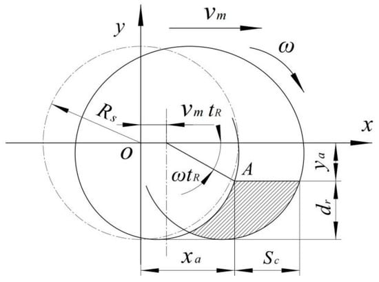
Figure 7.
Movement trajectory of rotating blade tip.
As illustrated in Figure 7, within the same cutting sub-area, the horizontal distance between the trajectories of two blades that successively enter the soil and cut is defined as the soil cutting pitch (Sc), and its calculation formula is:
where n1 is rotary speed. The value of Sc directly affects the quality of crushed soil [26]. Because the working sugarcane field is a mature land with heavy clay and high hardness, a smaller soil cutting pitch was selected, with a value of 8.0 cm. It is known that higher forward speeds necessitate increased rotary speeds. Based on the operating efficiency requirements and the commonly used forward gear of tractors (vm, ranging from 0.6 to 1.2 m·s−1), the speed range can be calculated to be 150~300 r·min−1.
Subsequently, the ratio of the linear speed of the blade tip to the forward speed is defined as the rotational speed ratio:
Thus, by deriving Equation (1) with respect to time, the blade tip velocity equation can be obtained:
where dr is tillage depth. Its analysis shows that only when λ is greater than 1 will vax be less than 0 at the maximum trajectory chord length. This means that when cutting soil, the rotary blade produces a backward throwing effect opposite to the forward direction. That is, the following numerical relationship exists:
The maximum tillage depth in ridge breaking is generally 200 mm, and the minimum rotation speed is taken as 200 r·min−1. After calculation, the rotary radius Rs needs to be greater than 258 mm and is finally determined to be 265 mm.
2.3.3. Design of Ridge-Breaking Surface of the Plough
The ridge-breaking working surface of the rear plough is a key structural element that affects the lateral soil pushing effect. If the plough width is narrow, less soil will be lifted, resulting in insufficient soil filling. And if the plough width is too large, there is a risk of damaging the buried root system. Therefore, the ridge-breaking working surface parameters are determined based on the ridge profile required for cultivation agronomy, as illustrated in Figure 3b above. Then, the initial design height of the plough is:
where w1 and w2 are widths of the ridge top and ditch bottom. Their expected values are 300 mm and 400 mm, respectively; η1 is natural repose angle of clay, experimentally calibrated to 40° [27]. After calculation, the hp is required to be greater than 293.7 mm.
As an additional design requirement, the plow prevents excessive soil overflow while directing particles rearward along the moldboard. For this, the total plough height Hr2 in Figure 8a should be at least 1.25 times hp, rounded to 370 mm. Furthermore, based on the observed distribution of stump widths, the maximum plow width (wrmax) is determined to be 700 mm. The width wm at the hinge position is set to 250 mm. Using these parameters, the current width-to-depth ratio (kr) reaches 1.9, meeting the functional requirements for turning and buckling [28]. The required ridge height hr for cultivating ratoon sugarcane is 150 mm. Taking into account the influence of soil dilatancy, it can be calculated that the required working depth dp is greater than 143.7 mm.
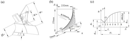
Figure 8.
Structural parameters of the plough. (a) Description of the overall structural dimensions. (b) Guide curve parameters. (c) Element curve changing with element line angle.
2.3.4. Determination of Diversion Surface Parameters of the Plough
The diverting surface of the ridging plough is hinged at the rear of the ridge-breaking surface and is responsible for laterally and rearwardly transferring soil particles. It is generated based on changing element lines that follow the guide arc curve. Depending on the plough body type, the ratio between the opening and height of the guide curve (Hr2/Lo) is set to 1.6, so that Lo is calculated as 232 mm. The calculation formula for the upper inclination angle of the guide curve is:
where εr is plow blade angle, taken as 25°; and σr is tangent angle, taken as 110° [29]. In this case, the Δεr can be determined to be 5°. Using these parameters, the arc of the guide curve formed by the envelope method is drawn in Figure 8b. The arc radius is rounded to 380 mm, and the straight length of the blade is designed to be an appropriate 70 mm.
For the element curve, it is designed by dividing the element line angle (θr) into two sections: First, in order to prevent the wing edge line from scratching turned-out soil, its minimum value (θrmin) should be smaller than the initial value (θro), so the first section is a decreasing straight line. Secondly, θr follows the form of a parabola increasing from θrmin to θrmax:
Therefore, the relationship between θr and the height Zr of the horizontal linear element is shown in Figure 8c. Thereinto, in order to balance the soil breaking and turning performance of the plough, θro is 37.5°, θrmin is 36.5°, and θrmax is 40°, respectively [29]. Then, the determined change equation of element line angle is:
Based on the above design parameters combined with cultivation agronomy, the main adaptability structure of the ridge-breaking plough is finally determined.
2.4. Simulation of Mass Transfer and Bearing Capacity of Rotary Tiller
2.4.1. Settings in Discrete Element Simulation
The fine-bladed rotary tiller plays a crucial role in breaking compacted soil and providing soil for subsequent ridging. The DEM enables an accurate and intuitive simulation of soil deformation and particle motion under soil-engaging components’ influence [30]. As shown in Figure 2, ratoon field soil exhibits inherent characteristics of heaviness, stickiness, and hardness. Therefore, the Hertz–Mindlin model with JKR (Johnson–Kendall–Roberts) for particle contact was selected. This model considers the normal linear adhesion force between particle contact surfaces, making it suitable for this type of heavy clay [31]. For the key JKR value that characterizes soil viscosity, the calibration value measured by our group on samples collected previously was used [32]. For the mechanical parameters of soil-engaging components, general values for steel are recommended. In addition, other parameters of soil particles and their interaction required for DEM simulation are comprehensively adopted from the calibration values in the literature [33,34], mainly based on the measured moisture content and hardness in Figure 2 that are similar to the conditions described in these documents for soils in South China’s growing regions. Detailed contact parameters between particles and soil-engaging components are summarized in Table 2.
Table 2.
DEM simulation parameters assigned to soil and components.
According to the designed working row spacing for the device, a particle soil bin with the dimensions of 1400 mm width and 300 mm depth was created in EDEM 2018 software to simulate the arable soil area. The conventional operating parameters of integrated earth cultivator were set as follows: a forward speed of 0.9 m·s−1, a rotary speed of 300 r·min−1, a cutting depth of 200 mm, and a stable working stroke of 3.6 m. To verify the effectiveness of the dense blade arrangement, the number of blades installed on a single cutterhead was varied as a study factor: 4, 8, and 12 blades, respectively. After generating the geometric model of the ridge-breaking soil cultivator, the discrete element interactions between it and soil particles were established. Figure 9a shows the calculation domain for particle mass accumulation, which was set up behind the cultivator to track synchronously. The amount of soil thrown by rotary tiller was thus calculated and used as a mass transfer index. This capacity value is important for evaluating the soil crushing and backward soil supply. Thus, this model can investigate how the dense tooth-blade configuration supports tillage and ridge formation.
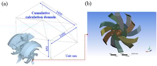
Figure 9.
DEM calculation model. (a) The setting of the throwing mass calculation domain. (b) Rotary blade group for finite element calculations.
2.4.2. Settings in Blade Load Simulation
The high-speed rotating blade teeth are subject to high shear stress from soil blocks in the compacted soil layer. This makes the originally welded rotary tiller parts prone to strength fractures, affecting operational reliability. To analyze the load stress distribution caused by the reduced cutting pitch, a finite element analysis of the dense spiral blade group was conducted using ANSYS 19.1 software, as shown in Figure 9b. The tetrahedral coordinated subdivision algorithm was used to mesh the geometric model. According to the actual materials used in manufacturing, the material properties of 65Mn steel, 45C steel, and 40Cr steel were assigned to the blades, cutterhead, and shaft, respectively. The elastic moduli of these materials were set to 206 GPa. The maximum instantaneous cutting force of 385.48 N, extracted from discrete element simulations, was applied as the working load to half of the soil-engaging blades in different models. The load direction was set perpendicular to the cutting edge surface. Cylindrical constraints were applied to the inner surface of the blade shaft hole. Subsequently, the maximum force on a single blade and structural stress distribution were obtained.
2.5. Field Experiment
2.5.1. Testing Conditions
A prototype of ridge-breaking earth cultivator was manufactured and equipped with 12 rake blades on each side of the dual rotary tillers. Field experiments were conducted in Fusui County, Chongzuo City, Guangxi Province, to test the actual working effect compared with the original cultivator. This field is located in the main advantageous sugarcane production area in South China, with typical climate, terrain, and soil conditions. Field operations were carried out in winter. At the required tillage depth of 20 cm, the soil parameters of the experimental plot were measured on site: the soil moisture content was 14.34% and soil hardness was 628 N·min−1. These soil parameter conditions were verified to be consistent with the characteristics of ratoon sugarcane fields previously described. As shown in Figure 10, the planting row spacing of 140 cm also meets the design specifications of the machine.
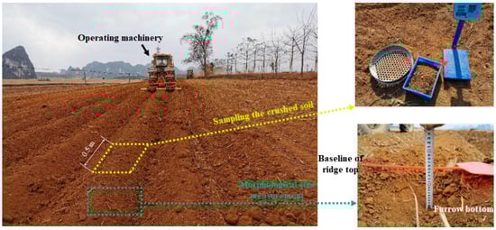
Figure 10.
Instructions for measuring soil fragmentation and ridge height in plots after operation.
2.5.2. Testing Scheme
To test the impact of main operating parameters on field performance, the forward speed (A) of the tractor (using Model LX1204 produced by Dongfanghong, First tractor company limited, Luoyang, China, with 88.2 kW power) and the rotary speed (B) were used as experimental variables. In terms of adjustability, forward speed and rotary speed were changed by shifting gears and calibrating the PTO (power take-off) pedal (using a photoelectric tachometer Type DT-2234B), respectively. The experimental matrix adopted the central composite design (CCD, taking the α value as 1.41). The coding settings of factor levels and their corresponding actual values are explained in Table 3 Eleven trials were conducted to enable subsequent modeling and optimization. During the soil cultivation process, the tillage depth was maintained at 20 cm by adjusting the telescopic extension of the tractor’s three-point hitch hydraulic cylinder and controlling the scale of plows.
Table 3.
CCD experiment matrix and field performance results.
On this basis, in order to analyze the comprehensive performance from the two aspects of ridge-breaking soil fragmentation and formed ridge height, two types of test indicators were defined. First, the soil fragmentation rate (SFR) was measured based on a particle size cutoff standard of 25 mm. It is calculated by weighing the proportion of the extracted qualified mass (Mq) that meet the crushing criteria to the total sample mass (Mtotal):
On the other hand, detecting the formed ridge height (RH) is the most direct way to judge whether effective filling can be achieved. Therefore, ridge height data Hi were measured every 2.0 m along rows, as explained in Figure 10. The indicator was obtained by calculating the average of n (n ≥ 10) measured values:
Additionally, in order to evaluate the cutting resistance between the improved and conventional rotary tillers, their breaking torque was measured in real time using strain gauges. Figure 11a shows specialized strain gauges symmetrically attached to the tractor’s power take-off shaft at 180° intervals, forming a full-bridge measurement circuit. The breaking torque resistance (T) was measured in real time using the installed wireless signal nodes, as shown in Figure 11b. The operation process of the earth cultivator involves gradually cutting into the soil layer to a predetermined depth and then maintaining that depth. Therefore, the curve changes gradually from zero in the initial stage to a relatively stable range. Meanwhile, the soil in ratoon field is uneven and contains compacted clay clods of varying sizes. Consequently, the rotary cutting torque exhibits periodic fluctuations. Overall, these dynamic curve data reflect the real field conditions. Finally, the effective value of the curve (i.e., root mean square, RMS) was extracted through eigenvalue analysis, and the experimental rotary tillage power (Pr) was calculated using the following formula:
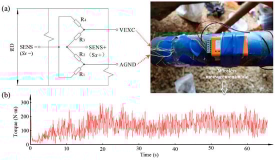
Figure 11.
Detection method and dynamic data of rotary tillage torque. (a) Measurement circuit and wiring. (b) Measured torque curve.
3. Results and Discussion
3.1. Analysis of Soil Quantity Thrown
Figure 12 shows the simulation of the interaction between rotary tillers, equipped with 4, 8, and 12 rake blades per cutterhead, and the soil. The red–green–blue color sequence represents decreasing particle motion speed. The simulation clearly shows soil particles being lifted, accelerated, and thrown backward. By comparing the particle flow effects among different blade groups, it is evident that the soil cutting and throwing effects are most pronounced in the case of 12 blades. This configuration shows the highest number of particles in red.
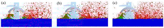
Figure 12.
Rotary tillage process using different number of blades: (a) 4 rake blades; (b) 8 rake blades; (c) 12 rake blades.
Furthermore, from the steady-state operation, the maximum instantaneous force on a single rake blade and the total mass of soil thrown backwards were extracted. The correlation curves between the number of installed blades and these values at a forward speed of 0.9 m·s−1, a rotary speed of 300 r·min−1, and a cutting depth of 200 mm are shown in Figure 13. As the number of blades increases, the load level on the blades decreases significantly, and the amount of soil thrown increases significantly. This indicates that the dense blade arrangement design with a maximum of 12 blades on one side is beneficial for improving the load-bearing reliability of rotary tiller components. The principle behind this improvement is to reduce the cutting pitch reasonably, thereby providing more soil for subsequent ridging.
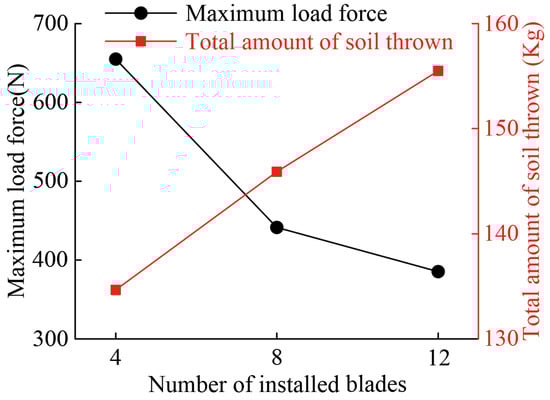
Figure 13.
Variation in blade load force and soil throwing amount with blade numbers.
3.2. Analysis of Blade Load Stress
The Mises equivalent stress distribution of the improved rotary tiller is shown in Figure 14a. The maximum deformation occurs at the tangent edge of the blade. The stress concentration under load is located at the fastening connection area where the blade transmits force to the cutterhead. The maximum stress value at this location is 89.82 MPa. Considering that the load is actually an impact load, a dynamic safety factor of 2.5 is adopted. Thus, the working stresses of key components are all less than the allowable stress values for the materials used: 172 MPa for 65Mn steel, 142 MPa for 45C steel, and 216 MPa for 40Cr steel. It is concluded that the improved blade set structure fully meets the material strength requirements. In contrast, the stress distribution of the original rotary tiller is shown in Figure 14b. The maximum stress concentration is located at the welded corner between the blade and its holder. The maximum stress value at this location is 193.57 MPa. This value has exceeded the allowable stress of 65Mn, making it prone to fracture during field operations.
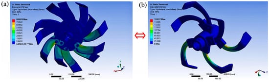
Figure 14.
Comparison of equivalent stress distribution. (a) Improved cutterhead structure. (b) Original cutterhead structure.
The comparison shows that under the same load and constraint conditions, the deformation and stress values of the newly improved rotary tiller structure are lower than those of the original. Consequently, the structure offers higher structural strength for handling compacted soil. Correspondingly, in large-scale field operations, it was found that the incidence of blade damage or even breakage of the improved rotary tiller was significantly reduced. This proves that its reliability has been improved to a certain extent.
3.3. Analysis of Ridge-Breaking Soil Cultivation Performance
3.3.1. Effects of Operating Parameters
The results of field performance tests for the earth cultivator under different operating parameters are shown in Table 3. Table 4 presents the analysis of variance (ANOVA) for various quality assessments in terms of soil fragmentation and accumulation. The linear and quadratic regression models for these two indicators are highly significant (p < 0.01), and their response surfaces are shown in Figure 15. For the ridging height, the peak appears at intermediate levels, indicating that the ranges of variables are appropriate.
Table 4.
Comprehensive ANOVA on ridge-breaking soil cultivation performance.
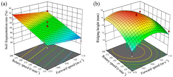
Figure 15.
Response surface analysis. (a) Soil fragmentation rate (SFR). (b) Ridge height (RH).
Regarding soil fragmentation rate, a lower forward speed combined with a higher rotary speed results in smaller cutting pitch. The SFR values are thus higher, which is consistent with the design theory explained in Section 2.3.2. Furthermore, rotary speed has the most significant effect on the RH. Increasing rotary speed generally increases the amount of soil thrown, effectively enhancing ridge filling. However, excessively low or high feed speeds do not facilitate soil supply, delivery, and lateral accumulation, thereby reducing the RH values. Overall, the optimal combination of operating parameters is crucial for ridge formation. The significant gradient changes in the response surfaces indicate that the optimal performance solution set for balancing ridge-breaking and earth cultivation lies within a relatively small design space.
3.3.2. Optimization and Validation of Improvements
Based on the response surface results, approximate models of these two types of indicators on ridge-breaking and ridging are established as:
where the goodness-of-fit (i.e., regression coefficient R2) is greater than 0.9, covering the entire design space. To obtain the optimal parameter combination that coordinates the performance of ridge-breaking and earth cultivation, a weight of 0.5 is used for both objectives. In this way, the multi-objective optimization problem can be expressed as:
The optimal design solution set obtained by using the multi-objective genetic optimization algorithm is a forward speed of 0.85 m·s−1 and rotary speed of 289.7 r·min−1. Using such operating parameters, the predicted SFR reaches a more complete fragmentation degree of 91.7%, while the RH reaches a higher 16.7 cm. Consequently, after adjusting to the optimal parameters, field verification tests demonstrate that the optimized SFR is 89.1% and the RH is 16.2 cm, both with prediction errors of less than 3%. Validation shows that the operating performance has been actually improved through optimization.
Subsequently, comparative experiments conducted under the same operating parameters shows that compared with the conventional cultivator, the SFR and RH of the improved earth cultivator were increased by 12.4% and 38.5%, respectively. The improved earth cultivator has demonstrated enhanced capabilities in soil breaking, lifting, and conveying, resulting in increased soil coverage for ratoon cane stumps. In addition, the calculated Pr of the improved cultivator (5.88 kW) was significantly reduced by 39.6% compared with the original cultivator (9.73 kW). This verifies that the new cultivator achieved better breaking and ridging capabilities while saving soil-breaking energy consumption. The above results provided direct experimental evidence for the comprehensive performance improvements of the integrated machines and tools.
4. Conclusions
- (1)
- To address the compacted and cohesive characteristics of ratoon cane farmland, an integrated earth cultivator structure was designed. This structure efficiently adapts to the new agronomic practice of ridge-breaking earth cultivation. The tool first loosens the soil through the ridge-breaking front plow, then crushes and elevates soil particles with the high-speed rotating dense rotary blade set. At the same time, it cooperates with the internal gathering effect of the deflector. Finally, it pushes the soil to form ridges by relying on the lateral extrusion of the rear plow. The mass transfer coordination of multiple soil-engaging components is used to focus on improving crushing and pushing capabilities. This approach promotes the degree of fragmentation and enhances the filling capacity of the cultivated soil.
- (2)
- The rotary tiller is designed with blades that are densely arranged in a short spiral pattern. Based on the kinematic analysis of the cutting pitch, structural parameters of the rotary tiller, such as the rotary radius, are determined. These improvements increase the cutting frequency in each sub-area and reduce the unit cutting load. Combined with DEM and FEM simulation results, it is shown that the blade load level significantly decreases as the number of blades increases. Simultaneously, the amount of soil thrown increases correspondingly, proving that the dense-toothed cutterhead has higher soil supply capacity and strength reliability. The ridge-breaking working surface parameters of the plow are mainly determined based on cultivated terrain specifications. The diversion surface parameters aim to balance upturned and transverse driving forces.
- (3)
- Field experiments are conducted using the response surface methodology. The influences of operational variables on the SFR and RH exhibit significant linear and quadratic regression. A lower forward speed combined with a higher rotary speed generally results in higher SFR values. The rotary speed has the most significant impact on RH, indicating that its increase can enhance the ridge filling amount by increasing the amount of soil thrown. The parameter combination obtained by multi-objective optimization is a forward speed of 0.85 m·s−1 and rotary speed of 289.7 r·min−1. With this optimal configuration, the SFR, RH, and Pr results are improved by 12.4%, 38.5% and 39.6%, respectively, compared with the values of the conventional cultivator under the same operating conditions. Further validation shows that this ridge-breaking earth cultivator improves crushing and ridging abilities as well as energy consumption performance.
Author Contributions
Conceptualization, B.Z.; methodology, B.Z. and J.C.; software, J.C. and Y.Z.; validation, B.Z. and J.C.; investigation, J.C. and Y.Z.; writing—original draft preparation, B.Z.; writing—review and editing, B.Z. and J.C.; funding acquisition, B.Z. All authors have read and agreed to the published version of the manuscript.
Funding
This research was funded by the Chinese Postdoctoral Science Foundation (Grant No. 2023MD734147) and the Guangxi Major Science and Technology Special Project (Grant No. Guike AA22117004-1).
Institutional Review Board Statement
Not applicable.
Data Availability Statement
The data reported in this study are contained within the article.
Conflicts of Interest
The authors declare no conflicts of interest.
References
- Huang, D.; Huang, K. Analysis on cultivation and management technology of sugarcane with “three high” trait. Guangxi Sugar Ind. 2021, 6, 13–16. [Google Scholar]
- Liu, S.; Jian, S.; Li, X.; Wang, Y. Wide–Narrow Row Planting Pattern Increases Root Lodging Resistance by Adjusting Root Architecture and Root Physiological Activity in Maize (Zea mays L.) in Northeast China. Agriculture 2021, 11, 517. [Google Scholar] [CrossRef]
- Patnaik, J.R.; Nayak, P.K. Optimizing Irrigation Water Scheduling of Sugarcane Planted Under Furrow Method with Trash Mulch Combinations for Enhancing Cane Productivity and Water Use Efficiency. Sugar Tech. 2024, 26, 370–375. [Google Scholar] [CrossRef]
- Zhong, K.; Zhang, D.; Sun, Y.; He, X.; Jiang, M.; Chen, W.; Li, J. Regional Trial and Cold Resistance Evaluation of New Sugarcane Varieties in Guilin. South. Hortic. 2021, 32, 18–23. [Google Scholar]
- Viana, J.L.; De Souza, J.L.M.; Auler, A.C.; De Oliveira, R.A.; Araújo, R.M.; Hoshide, A.K.; De Abreu, D.C.; Da Silva, W.M. Water Dynamics and Hydraulic Functions in Sandy Soils: Limitations to Sugarcane Cultivation in Southern Brazil. Sustainability 2023, 15, 7456. [Google Scholar] [CrossRef]
- Luo, Y.; Wang, W.; Zhu, Q.; Liang, T.; Chen, Y.; Xie, J.; Liu, X. Experiment on Different Row Spacing of Small-scale Mechanized Planting of Sugarcane. Guangxi Sugarcane Canesugar 2010, 2, 7–10. [Google Scholar]
- Li, R.; Huang, Y.; Huang, Y.; Liang, H.; Kuang, W.; Wei, C.; Mo, Q.; Chen, C. Study on Agronomic Factors Affecting the Quality of Sugarcane Stalks Mechanically Harvested. Guangxi Agric. Mech. 2013, 4, 9–12. [Google Scholar]
- Momin, M.A.; Wempe, P.A.; Grift, T.E.; Hansen, A.C. Effects of Four Base Cutter Blade Designs on Sugarcane Stem Cut Quality. Trans. ASABE 2017, 60, 1551–1560. [Google Scholar] [CrossRef]
- Lv, J.; Liu, Z.; Wang, P.; Li, Z.; Li, J.; Liu, Z.; Yang, D. Design and experiment of driving-type crushing-weeding multi-functional potato cultivator. Trans. Chin. Soc. Agric. Eng. 2019, 35, 1–8. [Google Scholar]
- Kudzaev, A.B.; Korobeinik, I.A.; Tsgoev, A.E.; Tsgoev, D.V.; Kalagova, R.V.; Urtaev, T.A. Development of Closed-Circuit Elastic Mounting for Working Bodies in the Interrow Cultivator. Civ. Eng. J. 2018, 4, 3027. [Google Scholar] [CrossRef]
- Zhang, R.; Sun, W.; Shi, L.; Wu, J.; Gao, S.; Li, Y.; Liu, X.; Zhao, Z. Design and test of the weeding cultivator and hilling machine in double ridge furrow with whole film mulch. Agric. Res. Arid Areas 2015, 33, 258–262. [Google Scholar]
- Zhang, X.; Tong, Z.; Li, L.; Li, Y.; Hou, C.; Xia, Y. Design and Experiment of Tobacco Hilling Machine for Compound Cutting. Trans. Chin. Soc. Agric. Mach. 2018, 49, 73–81. [Google Scholar]
- Khaehanchanpong, Y.; Ahamed, T.; Takigawa, T. Design, Fabrication and Performance Evaluation of an Inter-Row Cultivator for Sugarcane Fields. Inventions 2017, 2, 25. [Google Scholar] [CrossRef]
- Liu, Q.; Zhu, M.; Wu, T.; Zhou, J.; Luo, X.; He, T.; Zou, X. Design and Testing of a Diamond-Shaped Four-Wheeled Gantry-like Sugarcane Cultivator. Sugar Tech. 2021, 23, 1413–1424. [Google Scholar] [CrossRef]
- Wei, L.; Dong, X.; Li, M.; Huang, W.; Ge, C.; Niu, Z.; Chang, G.; Chen, J.; Liu, X.; Chen, X. Research Progress on Mechanized Deep Fertilization Technology and Equipment for Sugarcane in China. Agric. Dev. Equip. 2019, 3, 156–161. [Google Scholar]
- Gürsoy, S.; Chen, Y. Evaluation of Inter-Row Sweeps with Different Working Widths. Appl. Eng. Agric. 2017, 33, 307–312. [Google Scholar] [CrossRef]
- Bulgakov, V.; Pascuzzi, S.; Adamchuk, V.; Ivanovs, S.; Pylypaka, S. A Theoretical Study of the Limit Path of the Movement of a Layer of Soil along the Plough Mouldboard. Soil Tillage Res. 2019, 195, 104406. [Google Scholar] [CrossRef]
- Mudarisov, S.G.; Gabitov, I.I.; Lobachevsky, Y.P.; Mazitov, N.K.; Rakhimov, R.S.; Khamaletdinov, R.R.; Rakhimov, I.R.; Farkhutdinov, I.M.; Mukhametdinov, A.M.; Gareev, R.T. Modeling the Technological Process of Tillage. Soil Tillage Res. 2019, 190, 70–77. [Google Scholar] [CrossRef]
- Cheng, Y. The Ridging Performance Analysis & Optimization of Ridging Device of Potato Cultivator. Master’s Thesis, Xihua University, Chengdu, China, 2018. [Google Scholar]
- Tong, Z.; Xia, Y.; Zhang, X.; Wang, D.; Hou, C.; Wu, Y. Simulation Analysis of Spiral Knife for Banking Machine Based on Adams. J. Agric. Mech. Res. 2020, 42, 55–60. [Google Scholar]
- Akachi, T.; Miyahira, M.; Kuramoto, K.; Morita, T. Development of a Multipurpose Cultivator for Use in Sugarcane. In Proceedings of the International Society of Sugar Cane Technologists Congress, Okinawa Prefectural Agricultural Experiment Station, Okinawa, Japan, 30 March 2005; Volume 2, pp. 378–381. [Google Scholar]
- Kumar, M.; Thakur, T.C. Field Evaluation of Deep Soil Volume Loosener-Cum-Fertilizer Applicator for Management of Sugarcane Ratoon Crop. Agric. Mech. Asia Afr. Lat. Am. 2016, 47, 52. [Google Scholar]
- Shukla, S.K.; Lal, M.; Singh, S.K. Improving Bud Sprouting, Growth and Yield of Winter Initiated Sugarcane Ratoon through Tillage Cum Organic Mediated Rhizospheric Modulation in Udic Ustochrept under Subtropical Indian Condition. Soil Tillage Res. 2013, 126, 50–59. [Google Scholar] [CrossRef]
- Gao, X.; Liu, G.; Liu, S.; Guo, J. Research Progress in the Effect of Mechanical Compaction on Soil and Root Growth in Sugarcane Fields. Chin. J. Trop. Agric. 2020, 40, 29–34. [Google Scholar]
- Yang, Q.; Chen, G.; Xie, L.; Wang, Q.; He, J.; Li, H. Design and Experiment of Telescopic Finger Stalk of Maize Straw Burying Machine. Trans. Chin. Soc. Agric. Mach. 2020, 51, 35–43. [Google Scholar]
- Li, S.; Lin, J. Theory and Calculation of Driven Soil Tillage Machinery; China Machine Press: Beijing, China, 1997. [Google Scholar]
- Chinese Academy of Agricultural Mechanization Sciences. Handbook of Agricultural Machinery Design: Volume 1; China Agricultural Science and Technology Press: Beijing, China, 2007. [Google Scholar]
- Wei, G. Mechanism and Seed Bed Preparation Technology of Plowing and Rotary Combined Direct Seeder for Rapeseed. Ph.D. Thesis, Huazhong Agricultural University, Wuhan, China, 2022. [Google Scholar]
- Li, B. Agricultural Machinery; China Agricultural Press: Beijing, China, 2003. [Google Scholar]
- Zhang, L.; Zhai, Y.; Chen, J.; Zhang, Z.; Huang, S. Optimization Design and Performance Study of a Subsoiler Underlying the Tea Garden Subsoiling Mechanism Based on Bionics and EDEM. Soil Tillage Res. 2022, 220, 105375. [Google Scholar] [CrossRef]
- DEM Solutions Ltd. EDEM 2.4 Hertz-Mindlin with JKR Cohesion Model, 1st ed.; DEM Solutions Ltd.: Edinburgh, UK, 2011. [Google Scholar]
- Zhang, B.; Yang, X.; Wang, J.; Chen, J.; Shen, W. Construction of Rheological Model Based on Discrete Element Parameters Calibration of Clay from Sugarcane Cultivated Land. Trans. Chin. Soc. Agric. Eng. 2024, 40, 36–44. [Google Scholar]
- Xiang, W.; Wu, M.; Lü, J.; Quan, W.; Ma, L.; Liu, J. Calibration of Simulation Physical Parameters of Clay Loam Based on Soil Accumulation Test. Trans. Chin. Soc. Agric. Eng. 2019, 35, 116–123. [Google Scholar]
- Ma, L.; Huang, W.; Li, S.; Huang, Z.; Teng, X. Parameters Calibration of Discrete Element Model for Latosolic Red Soil of Sugarcane in Guangxi Autonomous Region. J. Agric. Mech. Res. 2023, 45, 18–26. [Google Scholar]
Disclaimer/Publisher’s Note: The statements, opinions and data contained in all publications are solely those of the individual author(s) and contributor(s) and not of MDPI and/or the editor(s). MDPI and/or the editor(s) disclaim responsibility for any injury to people or property resulting from any ideas, methods, instructions or products referred to in the content. |
© 2024 by the authors. Licensee MDPI, Basel, Switzerland. This article is an open access article distributed under the terms and conditions of the Creative Commons Attribution (CC BY) license (https://creativecommons.org/licenses/by/4.0/).