Article

An Experimental Analysis of the Seed-Filling Mechanism of Maize-Precision Hole-Planter Clamping

1
College of Mechanical and Electronic Engineering, Shihezi University, Shihezi 832000, China
2
Key Laboratory of Northwest Agricultural Equipment, Ministry of Agriculture and Rural Affairs, Shihezi 832003, China
3
Xinjiang Production and Construction Corps Key Laboratory of Modern Agricultural Machinery, Shihezi 832003, China
*
Author to whom correspondence should be addressed.
These authors contributed equally to this work.
Agriculture 2024, 14(3), 398; https://doi.org/10.3390/agriculture14030398
Submission received: 6 February 2024 / Revised: 20 February 2024 / Accepted: 21 February 2024 / Published: 1 March 2024
(This article belongs to the Section Agricultural Technology)

Abstract

:
Because the operating speed of current mechanical maize hole seeders is low and their ability to adapt to the seed is poor, an active clamping-type precision hole planter for corn was designed. Here, we explain its structural composition and working principle. According to the maize kernel size, the combination of hole parameters is based on the principle of virtual work on analyzing the seed extraction disc assembly’s static mechanical model. The model was imported into the ADAMS simulation for validation and the parameters and ranges affecting the seed-filling performance were identified. By further analyzing the results of the coupled ADAMS–EDEM simulation, the “arching” process of the seeds during leakage charging was revealed, and an arch-breaking method was proposed with the help of a swinging seed-collecting slider. The speed of the hole planter, the diameter of the outer edge of the gravity ring, and the angle of the block installation were used as test factors. The Box–Behnken center-combination simulation test was conducted using the sowing pass index, re-seeding index, and missed sowing index as evaluation indices. The experimental results show that the optimal parameter combination was as follows: gravity ring = 174.3 mm, stopper installation angle = 131.9°, and hole seeder speed = 85.2 rpm. At this time, the qualified seeding index was 94.53%, the multiple indices were 4.30%, and the leakage index was 1.18%. Under these conditions, the row seeding performance bench test was conducted to obtain the qualified seeding index of the hole seeder, which was 93.36%, while the multiple indices were 5.20% and the leakage index was 1.44%, which satisfied the agronomic requirements of precision seeding. This provides a theoretical reference for mechanical seeding methods for irregular seeds, as well as a basis for the research and development of maize precision sowing machinery and equipment.

1. Introduction

With its ternary structural attributes of a “grain-feeding economy”, maize has been the crop with the fastest increase in acreage and production in the world in recent years. China’s planted area for maize in 2022 was 3545 hectares, producing more than 554.4 billion kilograms [1]. Maize has overtaken rice as one of the top four grains in terms of planted area and production. Achieving a mechanization of the entire production process is an important means of reducing costs and increasing efficiency in large-scale maize cultivation. Precision sowing technology, as a key link in the mechanized production of maize, is of great significance to the development of the maize industry. Currently, the widely used mechanical-precision seed dischargers in China include the grooved wheel type, disc type, eyelet wheel type, and spoon clamp type. This type of seed discharger structure is simple, reliable, and inexpensive, but its suitability for sowing corn seeds is low, and its high-speed operation quality needs to be improved [2,3]. Therefore, there is an urgent need for technologies and programs suitable for the mechanized sowing of maize.
In recent years, scholars at home and abroad have carried out much research to expand the range of suitability for sowing with mechanical cavity seeders, including the seed-taking method of mechanical seed dischargers. At the same time, much research has been conducted on the seed–seed and seed–entity interaction mechanisms. In a study of innovative seed-taking methods, Zhang et al. [4] designed an oscillating clip pick-up-type precision seed discharger for maize, and the test results showed that the primary and secondary factors affecting the sowing qualification index were the opening and closing angle of the seed pick-up block, the rotational speed of the seed discharger, and the installation height of the seed feed cylinder. Dong et al. [5] designed an attitude-controlled, drive-guided precision seed discharger by constraining the seeds’ degrees of freedom and guiding the direction of seed casting, and the experimental results showed that when the attitude-adjusting teeth were linear, the seed discharge qualification rate was the highest, and it was always greater than 90%. Geng et al. [6] designed a tilted disc seed discharger, and the test results showed that its seed discharge pass rate was 91.3% under the optimal parameters. Wang et al. [7] optimized the design of a corrugated surface-type clamped seed discharger, which improved the qualified index by 12.34% compared to a general clamped seed discharger. Precision Planting and Kinze [8], USA, effectively reduced re-seeding by correcting the symmetrical inclination of the seed guide belt and the blade curve. In constructing models of seed–grain interactions, Wang et al. [9] took rectangular kernels as the research object to investigate the effects of the incident angle and incident velocity on the collision characteristics between the kernels, and the results showed that the change rule of the tangential contact force of maize kernels with the incident angle and incident velocity was not obvious, and there was a negative correlation between the rotational kinetic energy and the collision recovery coefficient. Zhao et al. [10] investigated the mechanical process of seed–solid collision in rice seeds, and the results showed that the contact force of centripetal collision increases with the radius of curvature and that eccentric collision seeds will rotate. Jun et al. [11] investigated seed–seed interactions based on the theory of mass-point and fixed-point collision dynamics, and the experimental results showed that the error between the simulated and real values was less than 10%. Horabik et al. [12] measured the collision recovery coefficients of three plants using a high-speed camera and concluded from the experimental results that a nonlinear relationship is more suitable for modeling the collision process in the case of irregular seeds with high moisture content. Although the above scholars have achieved certain results in related fields, the improvements in seed extraction methods still use spring devices, which are ineffective in improving the quality of high-speed operation and the range of suitability for sowing. A single particle, as the object of the study of the seed-filling process in this thesis, relies less on the method of mechanical seed dischargers and, at the same time, much work has been performed on the seed–seed and seed–entity interaction mechanisms in the study of innovative seed-taking methods.
In this study, an active clamping-type precision hole planter for corn was designed. The parametric design of the combined holes was based on the shape and size of the corn seeds. Static and dynamic modeling of the seed extraction discs were performed. The motion state of the seeds during seed guiding and filling was analyzed and verified through simulations. Based on the simulation results, the motion state of the individual seeds was investigated, the “arching” process of the seeds during leakage charging was revealed, and an arch-breaking method was proposed with the help of the swinging of the seed-collecting slider. The interactions between seed extraction discs and maize seeds were modeled using the discrete element method and kinetic coupled simulation. The seed displacer operating parameters were optimized using a three-factor, three-level Box–Behnken central combined simulation experiment, and the burrower’s operational performance was verified through bench testing.

2. Structure and Working Principle of the Hole Seeder

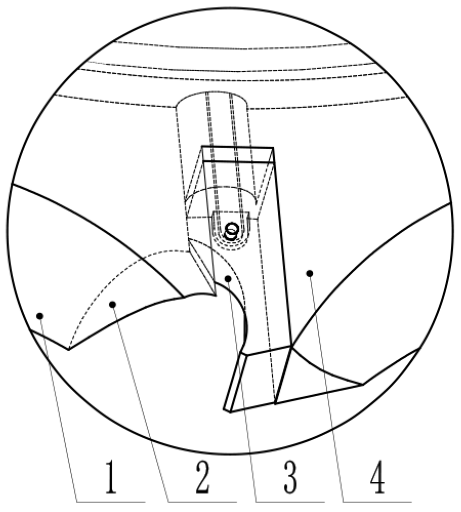
2.1. Overall Structure of the Hole Seeder

As shown in Figure 1a, the active-clamped corn precision hole planter mainly consisted of a seed intake tube, finalized disc, seed-picking disc assembly, seed cavity, seed discharge module assembly (duckbill hole former and girdle), and shaft. The components were bolted together to form the hole planter as a whole. Among them, the seed-picking disc assembly mainly consisted of a seed-picking disc, block, seed-picking slider, and gravity ring. As shown in Figure 1b, the 13 seed pick-up sliders in the seed-picking disc assembly were independent of one another. Each seed-taking slide was hinged to a gravity ring using a connecting rod, and the gravity ring was limited by two tabs on the inside of the seed-taking disc.
When working, the gravity ring rotated eccentrically in the semi-enclosed space formed by the seed-taking disc and the seed chamber, which controlled the opening and closing of the seed pick-up slider in the corresponding position.

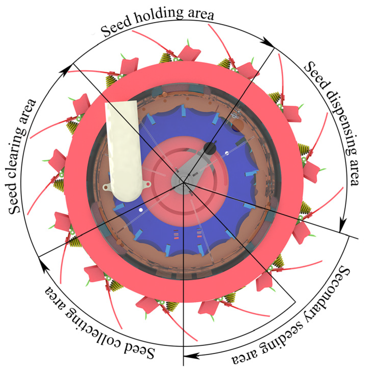
2.2. Operation Principle of the Hole Seeder

As shown in Figure 2, the working area of the hole planter was divided into a seed collection area, a seed-clearing area, a seed-holding area, and two seed-dispensing areas.
The clamping-type corn precision hole planter works as follows: The corn seed in the seed box enters the cavity of the hole planter through the seed intake tube under the effect of gravity, and the seed-picking disc rotates with the hole planter under the traction of the tractor. When one of the seed pick-up sliders on the seed-picking disc assembly enters the seed pick-up area, the seed pick-up slider moves outward under the synergistic action of gravity, centrifugal force, and the gravity ring to increase the volume of the combined-type holes. In the semi-enclosed cavity formed by the seed disc and the seed chamber, the gravity ring rotates with the seed disc while generating a small range of translational movement, which opens and closes the hinged seed pick-up slider radially through the connecting rod. Seeds are filled into the combined-type hole by gravity and interspecies interaction forces. Subsequently, the gravity ring under the action of the block drives the seed-picking slide to retract and stabilize the seed clamping. As the pick-up disc continues to rotate into the seed-clearing area, the unstable clamped seeds fall back into the population under the action of the seed-cleaning brushes, completing the seed-clearing. The steadily clamped seed enters the seed-dispensing area, and under the action of the retainer block, the gravity ring carries the seeding slider outward to force the seed into the seed guide tube while the duckbill is forced open into the soil to complete the sowing.

3. Parameter Design of Combined-Type Holes

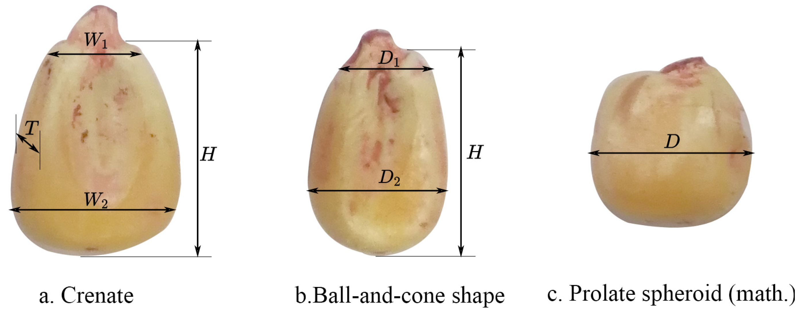
3.1. Geometric Parameters of Maize Seeds

The key to extracting seeds from pores is the shape of the pore and the relative movement between the pore and the seed. To adapt the holes to the shape of the seeds, an ellipse that approximately conforms to the shape of the seeds was initially selected as the beveled profile of the combined holes. The size of the holes varies from seed to seed depending on the characteristics of the seed material. In this study, Xian yu 335 (Pioneer Seed Research Co., Ltd., Tieling, China), which is more widely planted in Xinjiang, with a water content of 14.36 ± 1%, was selected. One thousand maize seeds were randomly selected for this study and statistically analyzed. The results are shown in Table 1. Corn seeds can be broadly classified into three categories based on their shape, as shown in Figure 3: trapezoidal front and rear surface profiles, with a width greater than the thickness of the tooth; narrow at the top and wide at the bottom, with a rounded tapered bottom; and spheroidal, with roughly equal thickness and width and a rounded surface. The corresponding dimensions and distribution probabilities are shown in the following table. In this study, we designed the parameters of the combined-type holes to maximize their adaptation to the three types of seed shapes.

3.2. Combined-Type Hole Design

3.2.1. Determination of the Number of Combined-Type Holes

The diameter of the seed tray is an important factor that directly affects the number of combined-type holes in the combination, and its size is linked to the seeding quality and structural dimensions of the hole planter. For high-speed precision hole seeders, if the diameter of the seed-taking disc is too small, its speed will be higher, which will shorten the time for which the combination of holes stays in the seed population, which is not favorable for seed filling. If the size of the center disc is too large for easy processing and maintenance, it increases the weight of the hole planter. Referring to the relevant literature [13] and “Agricultural Machinery Manual”, the seed disc’s diameter is generally 80–260 mm; in this study, it was 230 mm.
When the seeding rate is certain, the higher the number of combined-type holes, the lower the rotational speed of the disc, the longer the holes stay in the population, and the more favorable it is for seed filling; therefore, it is necessary to arrange as many holes as necessary to meet the requirements of the work, allowing for more favorable seed-filling conditions.
N = 60 v m x n ( 1 c )
Note: N is the number of combined-type holes; vm is the operation speed of the hole seeders, m·s−1; x is the distance between plants (within a row), m; n is the rotational speed of the hole seeder, rpm; and c is the slip coefficient of the ground wheels.
According to the agronomic requirements of maize planting, the maize-sowing row spacing takes the value range of 0.18–0.4 m, and, in this study, x = 0.18 m. The hole seeder is drawn by the tractor, and its operating speed is in the range of 0.5–0.9 m·s−1; in this study, 0.9 m·s−1 was the value. The corresponding speed of the seed extraction disc was 25 rpm. The ground wheel slip coefficient c = 0 for the bench test phase. The number of combination holes was calculated to be 13.

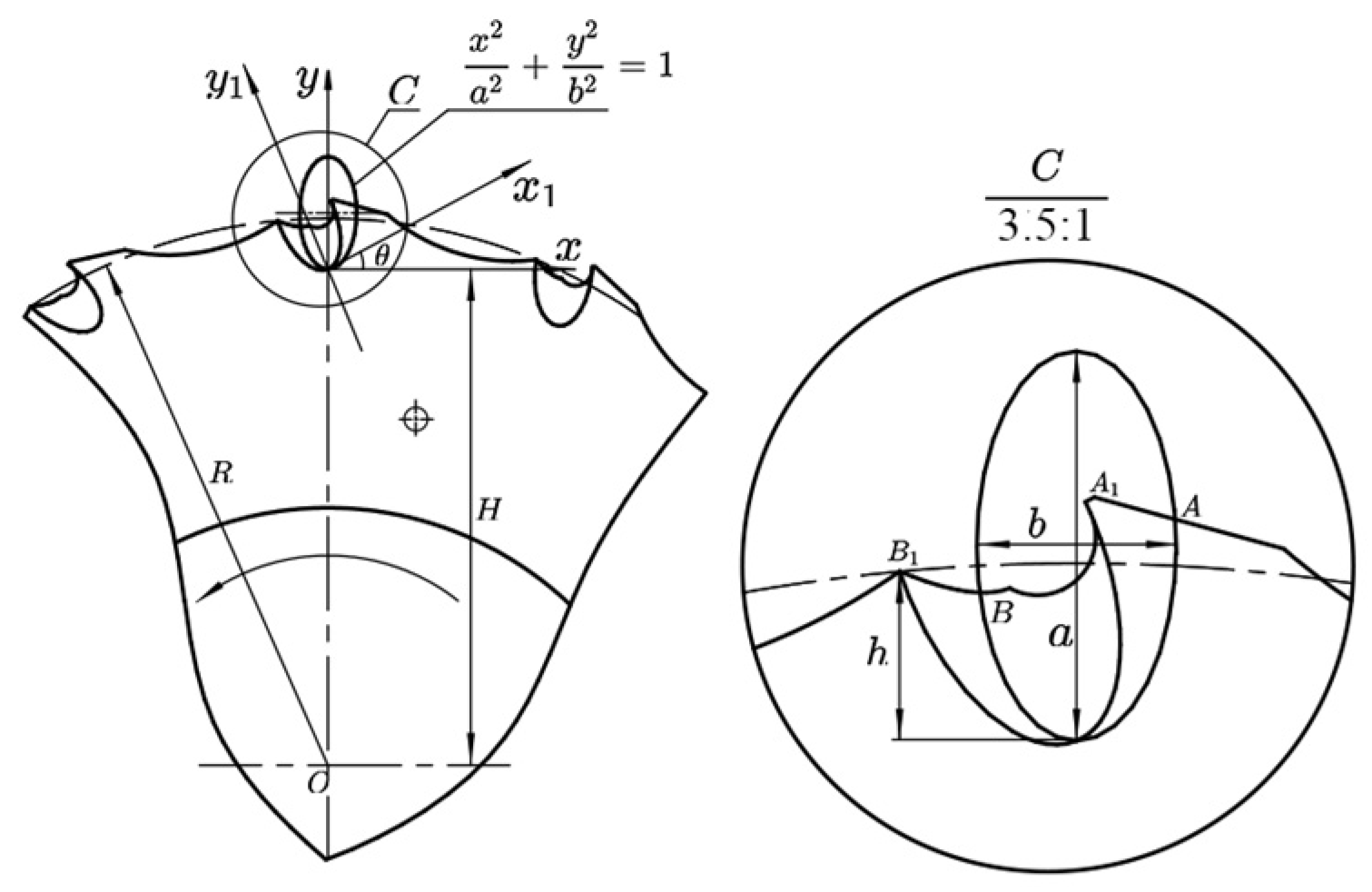
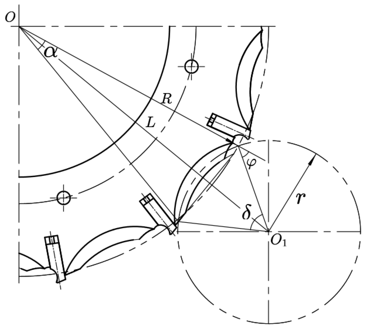
3.2.2. Determination of the Geometric Parameters of the Combined-Type Holes

Throughout the work, a seed extraction slider, through its law of motion, in the seed-collecting area was used to increase the volume of the combination of holes and the small-scale perturbation of the seeds around the seed extraction space to improve the performance of seed extraction. In the seed-clearing area, seeds that were not steadily gripped were squeezed out by the retraction of the seed pick-up slide and the seed-clearing brushes. In the seed-holding area, the seed was held steadily to avoid being thrown out at high speed. In the seed-dispensing area, a forced opening brought out the clamped seed to complete the seed drop to solve the problem of the seed-filling difficulty of maize seeds with large triaxial differences. In this study, we focus on designing the law of motion of the seed-picking slide, optimizing its operating parameters, and regulating the attitude of the seed to guide it into the combined-type holes.
The combined-type hole structure parameters were the core design parameters of the seed extraction disc. The seed pick-up structure of the active-clamping seed picker disc assembly included a combination of hole dimensions, inclinations of the seed discharge surface, and inclinations of the seed-holding surface, as shown in Figure 4. Among them, the inclination angle of the seed discharge surface and the inclination angle of the seed-holding surface refer to the previous research of the group [14]. To ensure that the combined-type holes could encapsulate the seed and hold it stably during the seed-carrying phase, the dimensions of the seed extraction structure needed to meet certain requirements. The length of the combined-type holes was too large, resulting in re-seeding or seed jamming, which reduced the seeding pass rate. If it was too small, this would have resulted in larger seeds not filling in and missed seeding. The depth h of the combined hole should be such that it is possible, and only possible, to hold a seed stably laterally.
The depth, length, and curvature of the seed discharge surface of the combined-type hole needed to be satisfied separately:
x 2 a 2 + y 2 b 2 = 1 x = x cos θ y sin θ y = y cos θ + x sin θ
h = a 2 k 2 + b 2 1 + k 2 ( W 1 , W 2 , D 1 , D 2 ) min 3 σ h ( W 1 , W 2 , D 1 , D 2 ) min + 3 σ L A B = 2 a b ( a 2 k 2 + b 2 ) ( 1 + k 2 ) a 2 k 2 + b 2 h 3 σ L A B h + 3 σ
Based on Equations (2) and (3) it can be seen that the values of a and b had a significant effect on the depth of the combined-type holes, and the larger the values of a and b, the deeper the combination of holes. k mainly affected the length of the combined-type holes; the larger k, the longer the combined borehole. Roughly shaped and shallow combined-type holes were unstable to carry seeds and prone to cavities. Combination holes with slender shapes made it easy to jam seeds. To ensure that the combined hole could accommodate one seed while not allowing two seeds to enter the combined-type holes at the same time, θ = 45° was selected in combination with the previous test. The a·b−1 values were selected mainly based on the shape and size of the seeds. According to the seed statistics, dimensions were taken as b = 4.5 mm and a = 7.9 mm, from which the equation of the combined-type holes curve was obtained as follows:
x 2 7.9 2 + y 2 4.5 2 = 1 , 3.91   mm < x < 3.91   mm

4. Analysis of the Working Process of the Seed Picker Disc Assembly

4.1. Seed Pick-Up Slider Motion Design

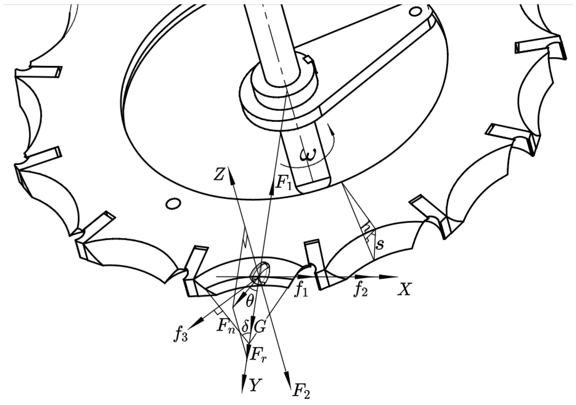
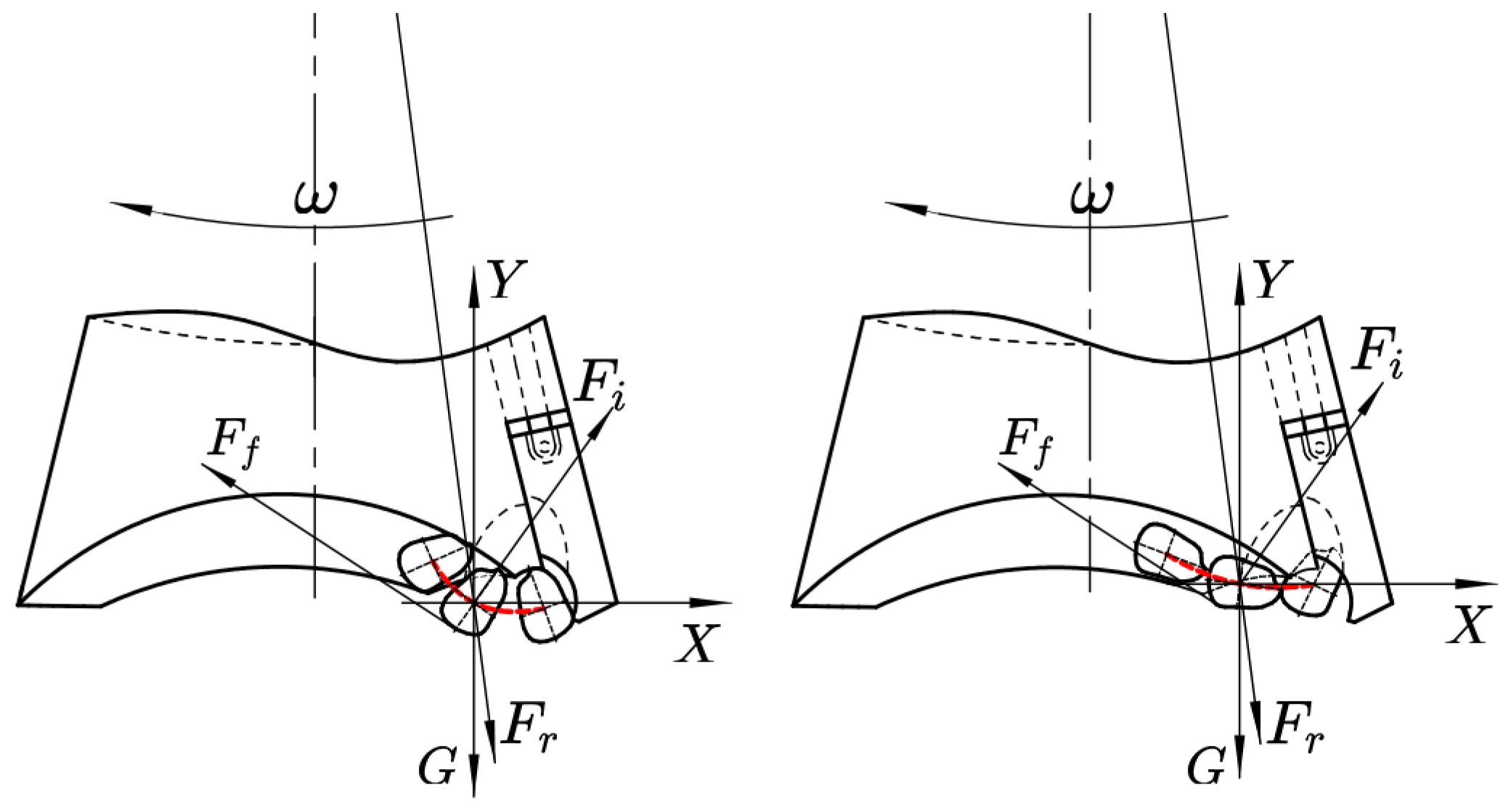
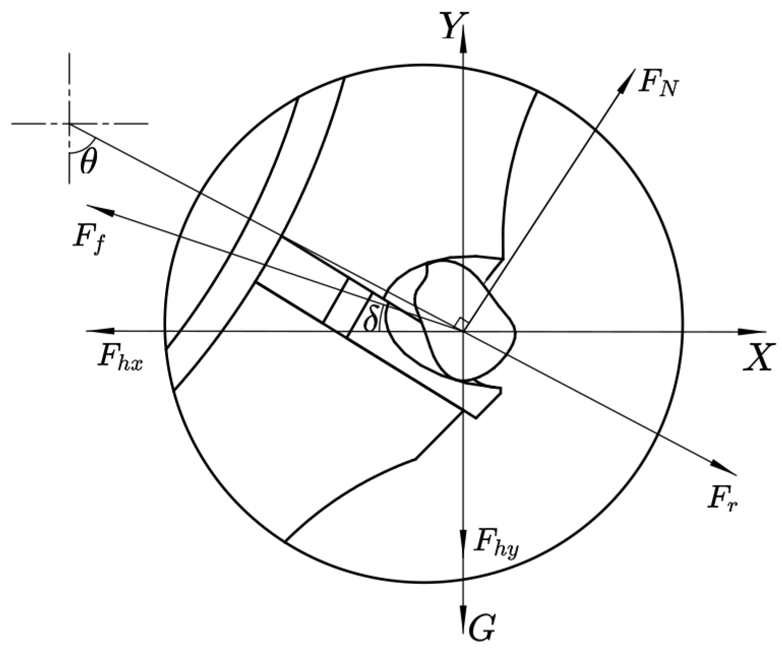
4.1.1. Mechanical Static Modeling

The movement of the seed pick-up slider was mainly controlled by the gravity ring and the position of the seed-taking disc. To make the motion trajectory of the seed-taking slider meet the requirements, in this study, the gravity ring of the rotating follower was used to establish the equations of the kinematics of the fetch slider based on its profile using inner edge guidance. To avoid damage to the seed caused by the opening and closing motion of the seed pick-up slider, the seed pick-up slider travel was limited by the outer and inner tabs of the seed-taking disc together. We used the law of motion of the sinusoidal function to reduce the impact of the seed-picking slider on the seed [15].
For the convenience of the study, the parts of the mechanism were regarded as absolutely rigid, and there was no friction force between the parts. The active force acting on the mechanism was denoted as F = mg. The relative positions of the components are shown in Figure 5. The gravity ring was free-falling only under gravity, and its equilibrium needed to satisfy geometric closure. In the static model of the analyzed mechanism, the principle of virtual work only considered the effects caused by the active force on the members, which was more concise and operational than traditional Newtonian mechanics. Therefore, in this study, the principle of virtual work was used to analyze the equilibrium state of the mechanism.
From the analysis, it is clear that this was a complete ideal system, taking q = θ.
The principle of virtual work under a complete ideal system can be expressed as follows:
i F i δ r i = 0
In this study, the center of the circle of the fixed mechanism was chosen as the origin to establish the coordinate system, and the active force was only gravity G. Therefore, the principle of virtual work can be written as follows:
m g δ h = 0
Taking θ as the generalized coordinates, using the cosine theorem according to the positional relationship in Figure 5 yields the following:
l 2 + h 2 ( R r ) 2 h 2 / cos 2 θ 2 l h = cos φ
The root formula can be used to obtain the value of the below:
h 12 = ( 2 l cos φ ± 4 l 2 cos 2 φ 4 tan 2 θ [ ( R r ) 2 l 2 ] ) / 2 tan 2 θ
According to the principle of least potential energy, the center of the gravity ring circle lies below the center of rotation, hence h < 0. Taking the negative sign of the above equation and applying the variable to the generalized coordinates θ yields the following:
δ h = ( tan θ 2 l 2 cos φ 2 a tan 2 θ 2 l cos φ 4 l 2 cos φ 4 a tan 2 θ ) δ θ
where a = (Rr)2l2. Let δh = 0, which simplifies to
tan θ = 2 l a + 1 cos φ 2 a + 1
Bringing the values in gives tan θ = 0.69. According to the geometrical relationship shown in Figure 5, h = 1.06 mm and, calculated from the Pythagorean theorem, d = 1.287 mm.
Therefore, the coordinates of the center of the circle after stabilization of the gravity ring with the mechanism at rest were −0.733 and −1.060 mm. When the active member rotated around the center of the circle with angular velocity ω, the vector sum of the centripetal forces was not zero because the thirteen-seed pick-up slider could not be perfectly symmetrical. However, due to the small mass of the seed pick-up slider (0.8 g), the eccentricity e was small (e < 0.01 mm) when the seed picker disc assembly rotated at a small speed (ω < 10 rad·s−1). Therefore, for simplicity of calculation, it was assumed that the center of rotation of the gravity ring continued to coincide with the center of rotation at rest after stable rotation. The equation for the trajectory of the gravity ring could be derived as follows:
x x 1 2 + ( y y 1 ) 2 = R 2
Applying the cosine theorem to the geometric relationship in Figure 5 yields the following:
b 2 = R 2 2 + d 2 2 R 2 d cos δ 0 φ 2 π
The relationship between the difference in distance e between the outer edge of the gravity ring and the inner edge of the seed-taking disc varies as follows:
e 2 = R 3 b = R 3 R 2 2 + d 2 2 R 2 d cos δ
The distance that the seed pick-up slider moves radially with the corner was the main factor to be considered when designing the slider motion, as can be seen from the above equation. When the inner diameter R3 of the seed-taking disc was constant, the travel of the seed pick-up slider was mainly determined by the outer diameter R2 of the gravity ring and the relative position between the seed-taking disc and the center of rotation of the gravity ring.

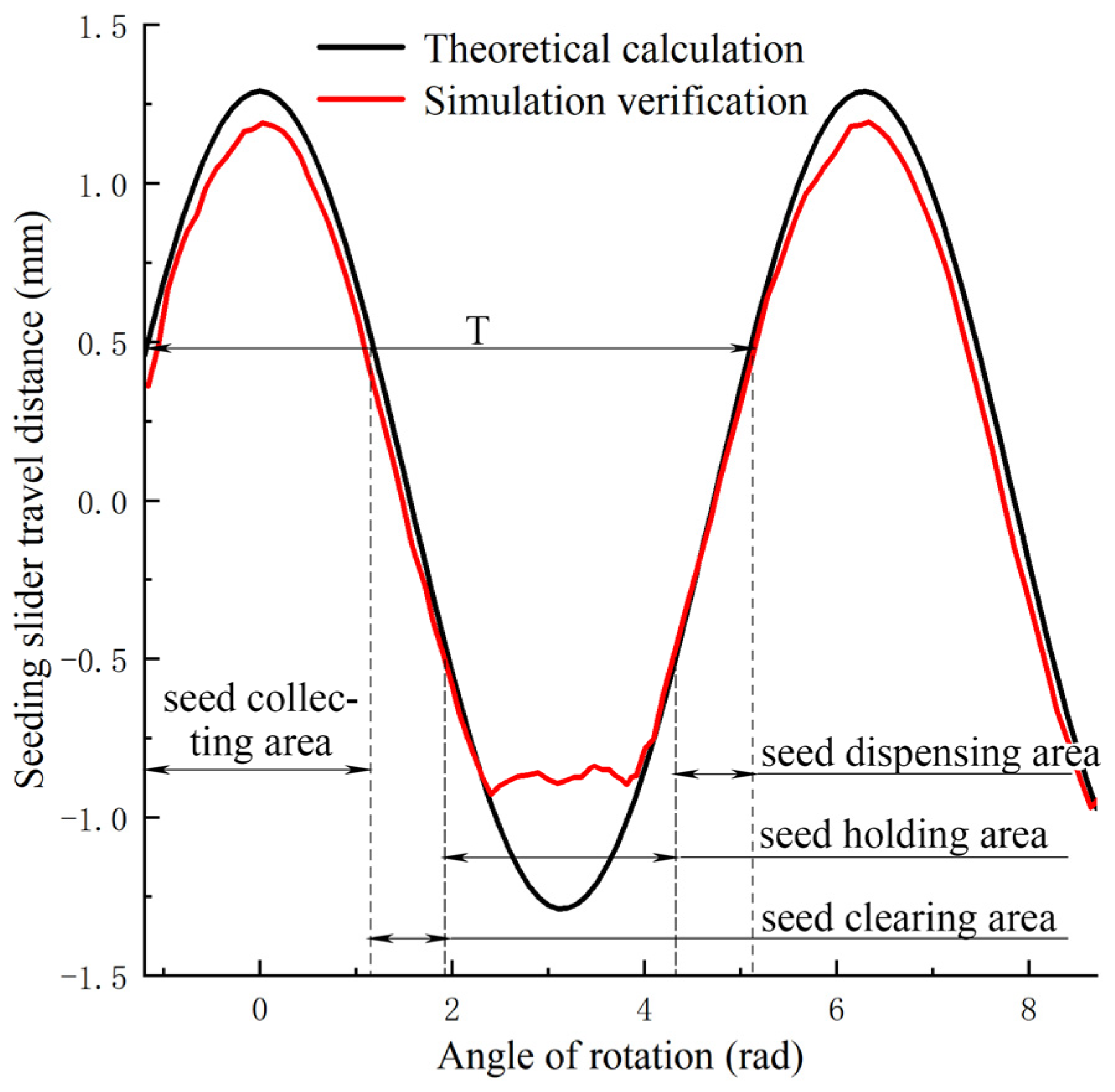
4.1.2. Kinematic Simulation and Verification of Seed Pick-Up Slider

In order to verify the theoretical analysis results, ADAMS was used to simulate the motion trajectory of the seed pick-up slider.
In this study, the first step was to build a 3D solid model of the seed picker disc assembly using Solidworks. To facilitate simulation and analysis, the mechanical model was simplified, and parts that did not affect the mechanical analysis were deleted. The model was saved as “x_t” and the format was imported into ADAMS 2020. Entities were integrated with unchanged relative positions through Boolean operations.
The appropriate forces, constraints, and motors were added according to the forces applied during the working process of the seed-taking disc assembly and the relative motion relationship between the components. Then, “maker” points were established on the centroid of the seed-picking slider and the center of the seed-picking disc, respectively. The simulation time was set to 10 s, with a working step size of 1000 steps per second.
The distance between the center of mass of the seed pick-up slider and the center of rotation was derived from the built-in function during the simulation. The simulation results and theoretical calculation results drawn using the origin software are shown in Figure 6. From the figure, it can be seen that the radial traveling distance of the seed pick-up slider varied periodically, with a maximum traveling distance of 1.3 mm. The larger the radial traveling distance of the seed extraction slider, the larger the range of adjustment of the combined hole volume and, therefore, the greater its adaptability to the seed, but the traveling distance was too large and led to an increase in the re-seeding rate. The forced seeding stage was not favorable for seeding when the seed pick-up slider moved too far. After the previous analysis, it could be seen that when the relative positions of the seed-taking disc and the center of rotation of the gravity ring were determined, the travel of the seed pick-up slider was only related to the outer diameter of the gravity ring. Combining the dimensions of the corn seeds and the previous pre-tests, the outer diameter of the gravity ring was set to be 74–84 mm, and the exact value was obtained through subsequent tests.
It can be seen from Figure 6 that the theoretically calculated values had the same trend as the simulated values. Except for the seed-holding phase, the relative error was 5.4%. The main reasons for errors include failure to take into account the change in the center of rotation at rest and work, as well as the interactions between the sliders of the taken species, which can also lead to different simulation results. In order to protect the seed, the seed pick-up slider was limited by the seed-picking disc cam, and its travel was restricted to carrying the seed only in the range of e = 1 mm.

4.2. Kinematic Analysis of the Seed Transfer Process

During the working process, the hole planter rotated to drive the movement of the seeds to the seed cavity. The movement of a single seed was completely random under the combined effect of friction force, population interaction forces, and centrifugal forces. However, the movement of the seed population showed a certain regularity. The population could be divided into ascending, collapsing, refluxing, and intermediate relatively stationary zones according to different patterns of movement. Only the seeds in the rising zone were in contact with the seed pick-up slider [16]. The relative velocity of the seed to the seed pick-up slider was one of the key factors in determining whether the seed could enter the seed pick-up slider. The smaller the relative velocity, the greater the probability that the seed would be taken by the sac. Seeds in the rising zone moved mainly by friction force with the seed cavity. After simulation, the angular velocity of the population in the ascending zone was closest to the angular velocity of the seed-taking disc. Seeds partially located on the inside of the seed-guiding surface were supported by the seed-guiding surface, with a difference in speed of less than 3% from the speed of the seed-taking disc. Therefore, the seed pick-up slider could pick up the seed from the rising area.
The curved seed-guiding surface coerced the movement of the seed by exerting a force on it. When the direction of the combined force did not cross the center of mass in the same direction as the direction of motion, the seed was stabilized by contacting the seed-guiding surface over a larger area, since the thickness of the seed-taking disc was less than the length of the corn seed. If the seed entered the inner space of the seed-guiding surface in a lengthwise direction, a torque effect was generated to rotate the seed in a population that was in two different states of motion inside and outside the seed. Thus, the final stable state of the seed subjected to the coercive movement of the seed guide was to slide or roll against the seed guide in the direction of the seed extraction slide.
The final steady state of the seed on the seed-guiding surface is shown in Figure 7. A spatial right-angle coordinate system was established, with the center of gravity of the seed as the origin, the line between the center of gravity of the seed and the corresponding height of the rotary axis as the Y-axis, the direction of movement of the seed at the current position as the X-axis, and a straight line passing through the O-point and perpendicular to the XOY-plane as the Z-axis. The forces on the seed in its steady state on the seed-guiding surface were analyzed.
m d v d t = f 3 cos δ f 2 f 1 F r + G + f 3 sin δ + F n cos θ F 1 = 0 F 2 = F n sin θ F r = m v 2 R F 1 = γ z Ω f 1 = μ 1 F 1 F 2 = ξ γ z Ω f 2 = μ 2 F 2 f 3 = μ 3 F n G = m g ξ = tan 2 ( 45 τ 2 ) cos θ = s h 0 δ 45
where: dv·dt 1 is the is the acceleration of the seed along the direction of the combined force, m·s−2; v is the speed of seed movement, m·s−1; γ is the specific gravity, kg·m−3; ξ is the lateral pressure coefficient; z is the population height, mm; τ is the friction angle of the seed, °; Ω is the surface area of the studied seed layer, m2; m is the seed mass, kg; g is the acceleration of gravity, m·s−2; R is the distance from the center of gravity of the seed to the rotary axis, m; and μ1, μ2, and μ3 are the kinetic friction factors between populations, the seed and the seed-containing cavity, and the seed and the seed-guiding surface, respectively.
The simplification is obtained as follows:
d v d t = μ 3 cos δ ( γ z Ω m g ) m cos θ + μ 3 m sin δ μ 3 v 2 cos δ R cos θ + μ 3 R sin δ μ 2 ξ γ z Ω + μ 1 γ z Ω m
From the above equation, since the angle of the center of gravity of the seed and the circle formed by the line connecting the center of gravity of the seed and the corresponding height of the rotor axis δ varied with the position of the seed, the direction and magnitude of the combined force on the seed also changed. When the working parameters of the hole seeder were certain, the acceleration could be changed by changing the size of μ2 and μ3 through the production of contact surfaces made of different materials or the treatment of contact surfaces. Coordinating the relative speed of movement of the pick-up disc and the seed increased the filling time in favor of the seed.
The static friction factor between corn seeds was μ1 = 0.2. The dynamic friction factor between the seed μ2 and the seed-guiding surface and the dynamic friction factor between the seed and the seed-holding cavity μ3 were in the range of 0–1. The hole seeder operating speed v = 3.5 km/h was brought into Equation (15) and calculated using Matlab to obtain a surface diagram of the thrust of the seed subjected to the seed-guiding surface, as shown in Figure 8a. From the figure, it can be seen that the thrust of the seed-guiding surface on the seed showed a gradual increase with the increase in μ3. However, its growth rate gradually slowed down, as shown in Figure 8b. Considering the machining accuracy and cost, we considered half of the highest growth rate, i.e., >0.45, as the cut-off point to meet the requirement. Seed extraction discs were proposed to be molded using PLA (polylactic acid) printing, the printing accuracy of the seed-guiding surface was selected to be 0.2 mm, and the kinetic friction factor between the seed-guiding surface and the seed was measured to be μ3 = 0.85 without machining. The seed-guiding surface thrust increased with μ2, but to a lesser extent. To facilitate the manufacture, the side wall of the seed cavity was formed by stamping an iron plate, and the kinetic friction factor between the surface and the seed μ2 = 0.32 was measured after the surface was flat and sprayed with antirust paint.

4.3. Kinematic Analysis of the Seed Extraction Process

The process of extracting seeds from a seed population is a complex one. During the working process, the seeds are subjected to a combination of gravitational, centrifugal, and inter-population interaction forces, forming a system in dynamic equilibrium. Seed extraction is the first step in precision seeding, and it is important to analyze the movement pattern of the seed population to reveal the seed-guiding mechanism for precision seeding.
According to the different stages of seed extraction, the seed extraction process is divided into a rotary-filling stage, a seed-holding and -following stage, and an oscillating clamping stage.
Rotary-filling stage: The process that occurs before the seed breaks away from the seed-guiding surface and enters the seed-holding space. After the seeds are detached from the seed-guiding surface, they continue to move towards the combined hole with an initial velocity of v0 under the force between the seed populations. Due to the mobility of the population, seeds detached from the guiding surface are in a constantly changing system of complex force chains. According to the results of the simulation experiments and the project team’s previous research, this stage of the seed will rotate and adjust under the action of the inter-population torque and enter the seed-picking space at an arbitrary angle. The angle at which the seed enters the holes of the combined pattern is the key to the rate of single grains in terms of the effect of seed picking.
Seed-holding and -following stage: Seeds filled into the combined-type hole are coercively rotated by the seed extraction disc. At this point, the seed is only subject to unilateral population pressure, avoiding seed detachment. For a successful filling of the combination of holes, due to the limitations of the seed extraction slider’s law of motion, it cannot be immediately retracted to the clamp; the seed in the seed-holding space with the combination of holes rotating at the same time can still be a small range of flat movement. The forced oscillation of the seed pick-up slider assists the seed in achieving a more stable attitude.
Oscillating clamping stage: The process in which the seed picker slider continues to rotate until it is in a straight line with the stopper, which is the rapid return phase of the seed picker slider. In this stage, the seed-taking slide is rapidly retracted to clamp the seeds under the drive of the connecting rod and, at the same time, the seeds that are not stably clamped are cleared away to achieve seed-taking.
In order to ensure the smoothness of the seed extraction process, a kinetic analysis of the rotary-filling stage process was carried out. As the key component of the seed picker disc assembly, its structure is schematically shown in the following Figure 9. The seed-holding surface and the seed-clamping surface together formed a seed-holding space in which the seed could be held. The size of the seed-holding space changed as the seed-picking slider slid. The outer contour of the seed-guiding surface was two concentric circular arcs, which were connected by a curved surface. According to the previous research results of the group, the arc inclination angle was taken as 51.3° [17]. The role of the end face was mainly to stir the seeds. The seed extraction discs were 3D printed from PLA, and the kinetic friction factor between its end face and the corn seed was determined to be 0.65.
From the previous kinetic analysis of the seed delivery process, it can be seen that after the structural and operating parameters of the seed-taking disc were determined, the thrust of the seed by the seed-taking disc was only related to the position of the seed on the seed-guiding surface. Taking μ2 = 0.32 and μ3 = 0.85, one could obtain the seed-guiding surface thrust as a function of the centroidal angle δ made by the center of gravity of the seed and the center of the arc, as shown in Figure 10. The maximum value of its thrust occurred on the circular surface close to the combined-type holes.
Calculating the velocity of seed movement on the seed-guiding surface was conducted according to the geometrical relationship shown in Figure 11.
α = ω t cos θ = ( R 2 + r 2 L 2 ) / 2 R r δ = 2 π 2 arccos θ α
where α is the number of radians of the round center angle of the seed-taking disc occupied by the seed-guiding surface, rad; δ is the number of radians of the circular angle made by the center of gravity of the seed and the center of the arc, rad; ω is the rotational angular velocity of the pick-up disc, rad·s−1; R is the radius of the outer circle at the bottom end of the seed-taking disc, mm; r is the radius of the arc at the bottom end of the seed-taking disc, mm; L is the distance between the centers of circles O, O1, and mm; and t is the movement time, s.
The simplification was obtained as follows:
δ = 2 π 2 arccos [ ( R 2 + r 2 L 2 ) / 2 R r ] ω t
Bringing in R = 113.5 mm, r = 40 mm, and L = 151 mm gives δ = −ωt + ψ; let ψ = 1.1076 rad. The original equation can be written as δ = −ωt + 1.1076, where ω = 5.23 rad·s−1. Bringing in Equation (15) yields the velocity of seed movement on the seed-guiding surface, as shown in Figure 12:
v = t 1 t 2 f ( x ) d t
v = t 1 t 2 [ μ 3 cos δ ( γ z Ω m g ) m cos θ + μ 3 m sin δ μ 3 v 2 cos δ R cos θ + μ 3 R sin δ μ 2 ξ γ z Ω + μ 1 γ z Ω m ] d t
As shown in Figure 13, the maximum velocity of the seed along the direction of rotation of the pick-up disc occurred in the section of the arc before entering the combined hole. The theoretically calculated value v = 0.58 m·s−1 reached 96.3% of the speed of the pick-up disc, which could be approximated as a zero-speed seed filling. To ensure the smoothness of the seed-filling process, the connection between the seed-guiding surface and the combined hole needed to be as smooth as possible. The seed pick-up slider opened so that the seed that was detached from the seed-guiding surface had the highest possible probability of falling into the combination-type hole.
m i g + i = 1 n F i + F r = m i d v d t M 0 ( m i g ) + i = 1 n M 0 ( F ) i + M 0 ( F r ) = I i d ω i d t
where mi is the mass of seed i, kg; Fi is the force on the seed by the population, N; Fr is the centrifugal force on the seed, N; v is the speed of movement of the seed off the seed-guiding surface, m·s−1; t is the time of movement of the seed off the seed-guiding surface, s; M0 is the moment of the force on the seed concerning its center of mass, N·m; Ii is the moment of inertia of the seed, kg·m−2; and ωi is the angular velocity of rotation of seed i, rad·s−1.
From the above equation, if you use the traditional seed tray in one state, the seed will be in its own gravity, with centrifugal force, population interaction force, and the combination of hole inlet surface support to reach a state of equilibrium, resulting in the “arch” effect. This results in the seed being stuck at the inlet of the combined hole and not being able to continue filling the seed. The seed stuck at the inlet falls back into the cluster under the action of the seed-cleaning brushes due to unstable clamping, resulting in an empty hole. Instead, seed-taking discs with radially sliding seed pick-up sliders are used. The forced oscillation of the slider can break its equilibrium so that the seeds stuck at the seed inlet can enter the combined hole or fall back to the seed population and thus continue to enter the state to be filled.

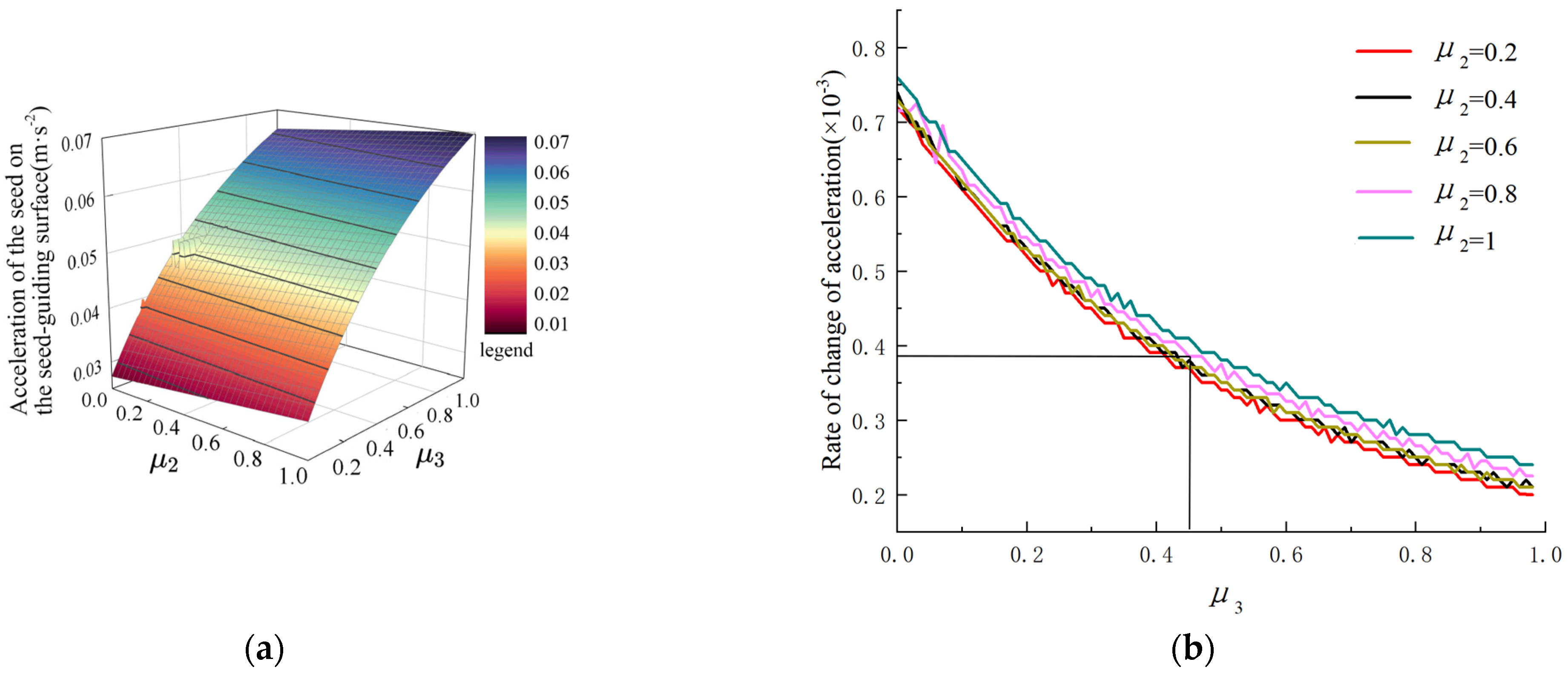
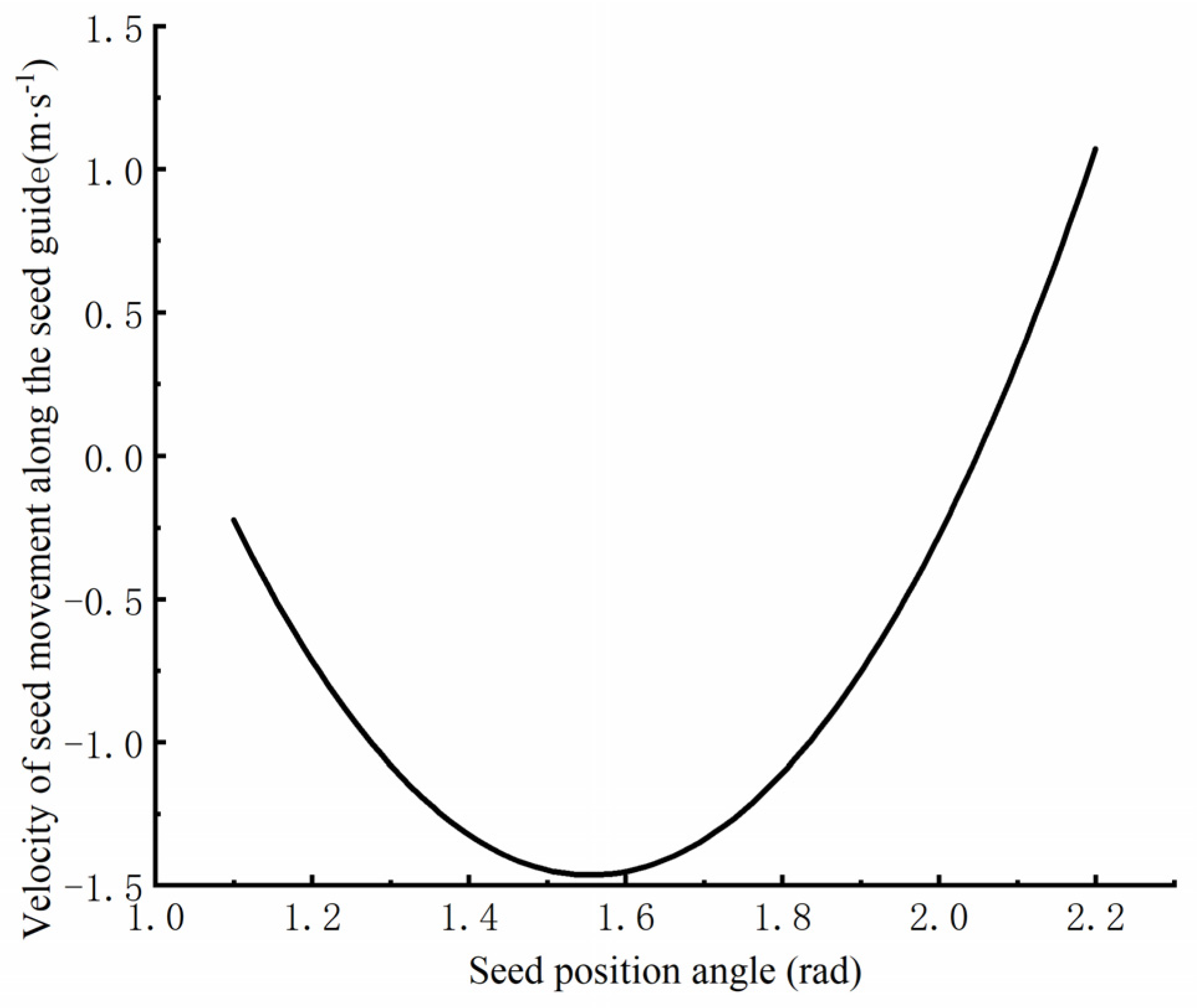
4.4. Analysis of the Limiting Speed of the Seed Extraction Disc

The seed extraction slider sacked the seed and then coerced the seed to follow the seed extraction disc. In the case of a successful seed filling, the seed was still subjected to compression and friction forces by the population as it continued to move through the population during the transport of the seed tray. At this point, the seed-picking slide had not retracted, and the seed was not stabilized in the seed-picking space. To avoid the seed-taking slide being out of the law of motion under the combined effect of gravity, centrifugal force, and the population causing cavities, the seed-taking disc speed should not be too fast. The speed of the seed picker disc when the seed picker slider was about to break away from the law of motion was the theoretical limiting speed of the seed picker disc.
A plane rectangular coordinate system was established with the center of gravity of the seed filling the seed-holding space as the origin. This neglected the effect of friction generated by the seed-taking disc and the seed surface on the force-coupling distance generated by the seed; the force analysis is shown in Figure 14.
F f cos δ + F h x F r sin θ F N sin δ = 0 F f sin δ + F N cos δ F r cos θ F h y G = 0 F f = μ F N F r = m ω 2 R G = m g ω = π n p 30 F h x = s ρ g R h F s ( 1 e K F s y R h ) F h y = s ρ g R h F s K ( 1 e K F s y R h )
where: ω is the angular speed of rotation of the pick-up disc, rad·s−1; np is the rotational speed at which the seed-taking disc operates, rpm; ρ is the density of maize seeds, kg·m−3; S is the cross-sectional area of the selected seed, m2; Rh is the hydrodynamic radius of the selected seed, m; K is the lateral pressure coefficient; and y is the distance between the combined-type hole and the seed surface, mm.
Bringing in the values gives the following:
ω = F h y + k F h x + m g m R ( k cos θ )
k = μ sin δ + cos δ μ cos δ sin δ
Once the volume of the seed cavity and the seed characteristics have been determined, the magnitude of the population force on the seed in the combined hole, Fhx Fhy, is mainly related to the height of the population. The higher the group height, the longer the holes of the assemblage move through the population, favoring seed filling. But, too high a population not only interferes with the clearing of seeds but also exerts a force on the seeding slider, preventing it from moving in a normal pattern. According to previous studies by the group and a review of the literature, the height of the population is generally 40–50% of the diameter of the sampling disc [19]. In this study, the population height was 93.6–117 mm. To calculate the limiting rotational speed of the pick-up disc, the maximum value of the height of the population was taken as y = 117 mm. The maximum speed of the seed picker disc was obtained by bringing μ = 0.85 mm, δ = 45°, R = 117.5 mm, g = 9.8 m·s−2, θ = 45°, and m = 3.17 × 10⁻⁴ kg into the above equation. Bringing in the above equation gave the maximum speed np = 115 rpm of the seed picker disc. Seed extraction discs were printed in PLA using 3D printing technology, and their maximum rotational speed was determined by pre-testing. With a population height of 117 mm, its initial speed was set to 30 rpm, and the speed was gradually increased. There was a significant increase in the cavitation rate when the speed exceeded 120 rpm, so the maximum value of the operating speed of the seed extraction disc was 120 rpm at 8.43 km·h−1.

5. Simulation and Analysis of Seed-Picking Process in Hole Seeding

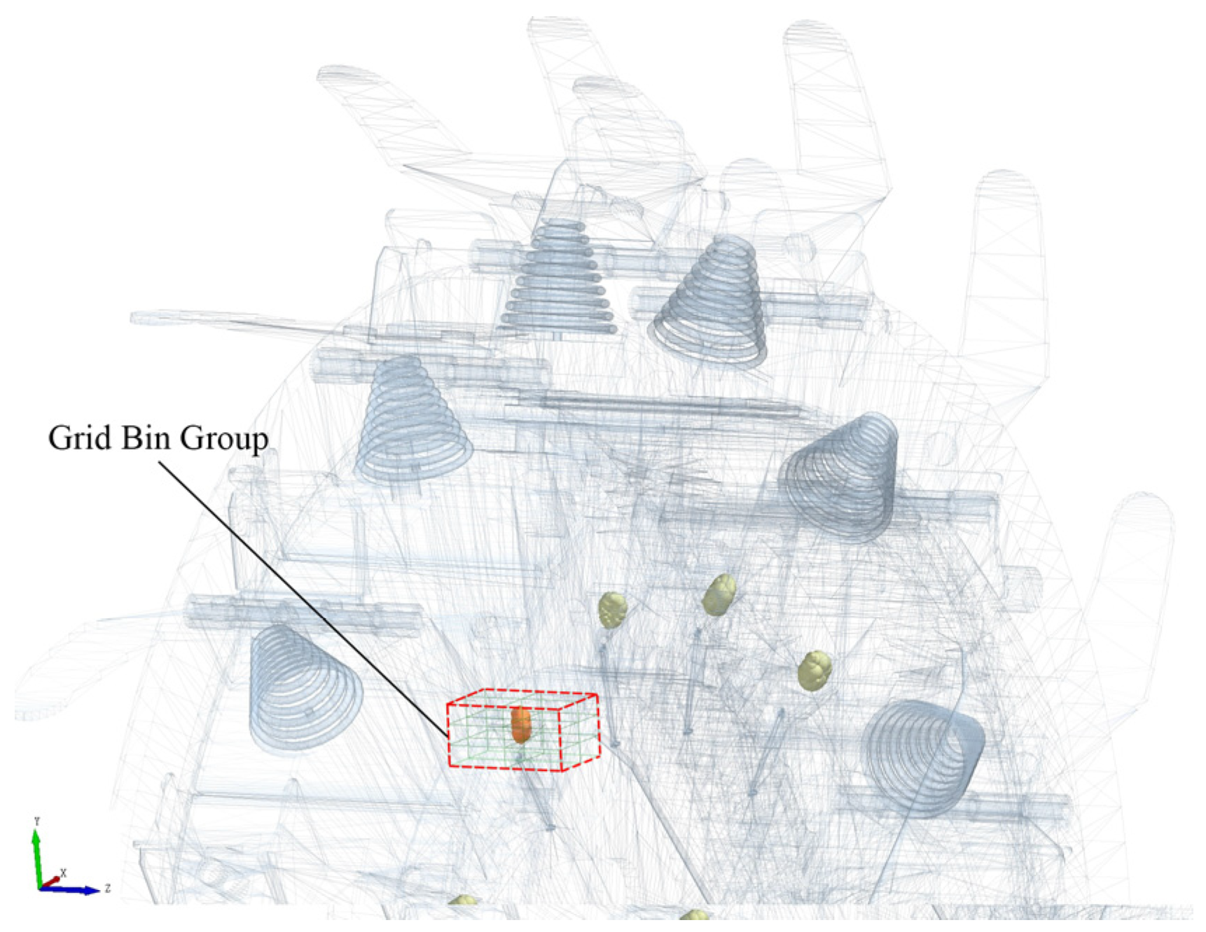
5.1. Simulation Modeling

The movement of the maize seed was unregulated due to the fact that, during sowing, the kernels were not only subjected to the interaction forces between the populations but also to the random collisions of the individual machine parts. It was difficult to analyze the movement pattern of the seeds through field tests or bench tests, so the movement state of the seeds during the working process was precisely observed with the help of the discrete element simulation software EDEM 2021. To simulate the radial sliding and forced oscillation of the seed-picking slider during the working process, it was necessary to simulate the working process of the seed-picking disc with ADAMS 2020 software. The theoretical analyses were validated using EDEM–ADAMS co-simulation. To reduce the amount of simulation calculation, the belt, seed-holding chamber, and duckbill were combined to simplify the stopper adjustment device.
The experiment was carried out using Xianyu 335 with a moisture content of 14.36 ± 1% for the study. According to the results of pre-screening, maize kernels can be classified into three types according to their shapes: toothed, bulbous conical, and spherical. According to the seed size to draw the 3D model and solid model imported into the EDEM software species for multi-spherical filling, the filling results are shown in Figure 15. The ratio of the number of generated teeth, spherical cones, and spheroidal shapes was set to 2:1:1.2. The Hertz–Mindlin non-sliding model was chosen as the virtual test contact model because there was no adhesion between grains. Table 2 shows the interaction parameters for particle–particle and particle–model and the model itself.

5.2. Seeding Performance and Testing

Refer to GB/T6973–2005 [27] Test Methods for Single-Grain (Precision) Sowing Machine and JB/T10293–2001 [28] Technical Conditions for Single-Grain (Precision) Sowing Machine for the test methods and evaluation indexes. The qualified index A, replay index D, and leakage index M were selected as evaluation indexes to evaluate the operation quality and stability of the seeder. The seed-taking scenario is shown in Figure 16.
n is the theoretical number of rows, n0 is the number of seeds per grain, n1 is the number of two or more seeds, and n2 is the number of holes without seed filling.
To facilitate the statistics of seed collection by each type of combined-type holes, a monitoring grid was established at the position where the picking disc passed through the seed-cleaning area, as shown in the Grid Bin Group monitoring block in Figure 17. The number of seeds passing through the monitoring block was counted over a continuous period and a line chart was drawn, as shown in Figure 18 below, to obtain qualified, excessive, and missing numbers.
It can be seen from Figure 18 that the seeding performance was in a straight line from 0 to 0.5 s. The number of seeds picked after 0.5 s increased with time. For individual time periods such as 0.7, 1.9, and 5.4 s, the ordinate value did not change. The ordinate value jumped around 1.2 and 4.3 s. Through data analysis, the seeder started to work stably from 0.5 s, the number of seeds did not change in two adjacent times to miss, and the number of seeds jumped in two adjacent times to replant. The picking performance of the seeder was stable after stable operation. Through an analysis of the images, the qualified index, replay index, and leakage index of the seeder could be obtained.

6. Seeding Performance Simulation Test

6.1. Test Program

Based on the theoretical analysis above, the outer edge diameter X1 of the gravity ring, the installation angle X2 of the stopper, and the rotating speed X3 of the seeder were taken as the test factors. Evaluation indexes included a qualified index, multiple index, and leakage index. The test was designed according to the Box–Behnken Center combination scheme. Based on the previous theoretical analysis and relevant literature, the value range of each factor was determined as follows: The outer edge diameter of the gravity ring was 172–174 mm, the installation angle of the stopper was 125°–145°, and the rotating speed of the seeder was 0.75–1.25 r·s−1. During the test, the working speed of the seeder was controlled by adjusting the rotating speed of the motor in ADAMS. The outer diameter of the gravity ring and the installation angle of the stopper were remodeled and adjusted with the software Solidworks 2021. The seed trays of each group of tests rotated for eight circles, and 104 combined holes were counted in total. The test was repeated three times and the average value was taken. The results were imported into Design–Expert 13.0 for data analysis, and the fitting regression equations between test factors and corresponding indexes were established. The optimal parameter combination was determined to provide the basis for the design of the seeder. Factor-level coding is shown in Table 3.

6.2. Analysis of Sowing Performance Test Results

The test data were imported into Design–Expert 13.0 for data processing. The orthogonal test scheme and results are shown in Table 4. Analysis of variance is shown in Table 5. After removing the insignificant terms, the fitted regression equations for the diameter of the outer edge of the gravity ring X1, the mounting angle of the stopper X2, the rotational speed of hole sowing X3 with the seeding pass index A, the re-seeding index D, and the missed sowing index M were obtained as follows:
The analysis of variance based on the results of the orthogonal test in Table 5 shows that the primary and secondary order of the effect of the test factors on the qualified index was the speed of the hole planter, the diameter of the outer edge of the gravity ring, and the angle of the block installation. The interaction term X1X2 of the diameter of the outer edge of the gravity ring and the angle of the stopper mounting had a significant effect on the qualified index, replay index, and leakage index.
Response surface plots of the effect of the interaction term X1X2 of the diameter of the outer edge of the gravity ring and the mounting angle of the stopper on the seeding pass index, re-seeding index, and leakage index were obtained using Design–Expert 13.0, as shown in Figure 19.
When the rotational speed of the hole seeder was 72 rpm, the installation angle of the block was larger or the diameter of the outer edge of the gravity ring was larger, the qualified index did not have an obvious trend with the change of a certain factor, and its mean value was larger. When the installation angle of the block was small or the diameter of the outer edge of the gravity ring was small, the seeding qualified index increased and then decreased with the increase in a certain factor. The replay index increased with the increase in the diameter of the outer edge of the seed force block and the angle of the block mounting when the speed of the hole seeder was 72 rpm. When the rotational speed of the hole planter was 72 rpm, the installation angle of the block was larger or the diameter of the outer edge of the gravity ring was larger, the leakage index did not change significantly with the change in a certain factor, and its mean value was smaller. When the block was mounted at a small angle or when the diameter of the outer edge of the gravity ring was small, the leakage index increased as a factor increased.
Analyzing the reasons for this reveals that when the diameter of the outer edge of the gravity ring was certain, with the increase in the installation angle of the block, the opening position of the seed-taking slide came gradually close to the lowest point of the seed-taking disc, and the seed-taking area was shifted to a certain extent toward the direction of seed-taking disc rotation. Due to the movement of the seed population driven by the hole seeder, the seeds in the rising area would likewise be offset in the direction of rotation so that the overlap between the seed-picking area and the rising area of the seeds increased, the seed-filling time was longer, and the qualified index gradually increased to the peak value. As the installation angle of the block continued to increase, the overlapping portion gradually decreased, and the shortening of the seed filling time led to a decrease in the qualified index and an increase in the leakage index. When the block installation angle was certain, as the diameter of the outer edge of the gravity ring increased, the opening stroke of the seed-taking slide increased, the volume of the combined hole gradually became larger, and the sowing qualified index gradually increased to the peak. However, too large a combined hole volume led to an increase in the row replay index and a decrease in the qualified index.

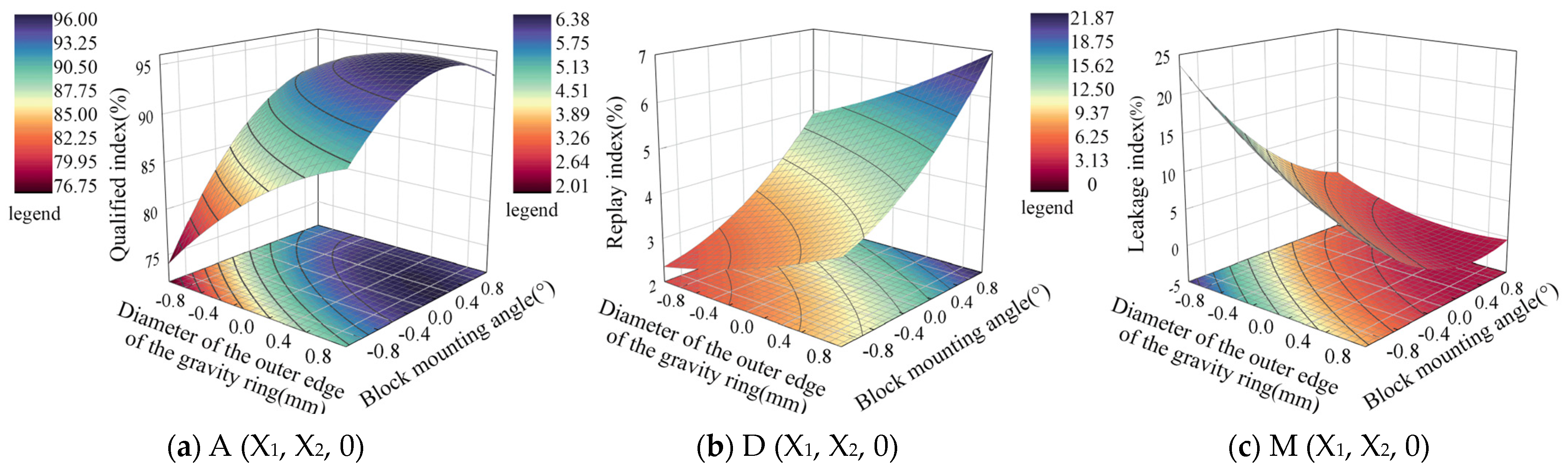
6.3. Parameter Optimization

To determine the optimal parameter combination for the hole seeder, the maximum row qualified index, minimum leakage index, and minimum replay index were used as the objective function, combined with the boundary conditions of each test factor. The multi-objective optimization analysis of the response surface equation of the seeding performance evaluation index was carried out, and the optimization model was obtained as follows:
s . t . 172 X 1 176 125 X 2 145 1.0 X 3 1.8 max i m i z e A ( X 1 , X 2 , X 3 ) min i m i z e D ( X 1 , X 2 , X 3 ) min i m i z e M ( X 1 , X 2 , X 3 )
Through analysis and calculation the optimal parameter combinations were obtained: diameter of the outer edge of the gravity ring, 174.3 mm; installation angle of the stopper, 131.9°; and speed of the hole seeder, 85.2 rpm, at which time the seeding qualified index was 94.53%, the multiple indexes were 4.30%, and the leakage index was 1.18%.

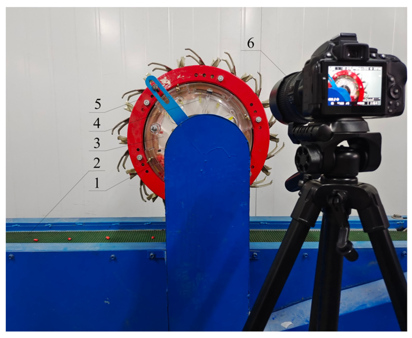
7. Bench Test Validation

To check the reliability of the simulation test, a seeding performance test was carried out based on the machining accuracy and the control accuracy of the test stand. Based on the machining accuracy and the control accuracy of the test stand, a physical prototype was made by taking the outer edge of the gravity ring as 174 mm, the installation angle of the stopper as 132°, and the speed of the hole seeder as 85 rpm. Benchtop validation tests were performed using national standards. The experiment was conducted at the Key Sowing Laboratory in Shihezi, Xinjiang. As shown in Figure 20, each group measured 300 points of data; the test was repeated three times to take the average value as the test results.
The test results are shown in Table 6. Under the optimal parameter combination, the seeding qualified index was 93.29%, the multiple indexes were 5.65%, and the leakage index was 1.04%, which verified the simulation results’ reliability and met the agronomic requirements of precision sowing.

8. Discussions

This study aimed to discuss the problems of the irregular shape of maize kernel, big size differences, and poor seed discharge performance. In this study, an innovative method and system for seed extraction with variable pore shape was proposed. It met the requirements for the precision sowing of maize in the sowing performance simulation test. The seeding pass rate was improved compared to traditional mechanical seeders. By quantitatively analyzing this device, we clarified the range of adjustment of the holes and the method of adjustment. Further, we could adjust the size of the holes so that they could be adapted to other varieties of maize seeds or even to other irregular seeds. Adaptation studies of the device will be the next focus of our team.
In our tests, we found that after some time, individual motion units had problems with sticking. We summarize the reasons for this through our analysis in two points: 1. low precision (0.2 mm) of the motion unit through 3D printing and 2. the print material was affected by the heat—the heat generated in the movement process made the movement unit expand, resulting in sticking. To solve these two problems, we will use a more precise way of making the kinematic units and machining them with a certain amount of clearance and make use of wear-resistant materials such as copper for motion units, etc. The device’s durability study is also our team’s next focus.
The seeding pass index of the bench test was low compared to the simulation test. The main reason for this is that bench testing generates vibrations. Vibration is a non-negligible factor in agricultural machinery [29,30,31], so the results of the bench tests were closer to the real situation. However, the bench tests had long lead times and did not allow for a detailed observation of seed movement. Therefore, simulating the vibration of the planter during operation through ADAMS–EDEM coupling made the simulation results more credible.

9. Conclusions

(1)
This study clarified the adjustment range of the hole and its influencing factors and revealed the force state of the seed in the process of seed guiding, filling, and carrying by analyzing the mechanics of the seed-taking process of the seed-taking disc.
(2)
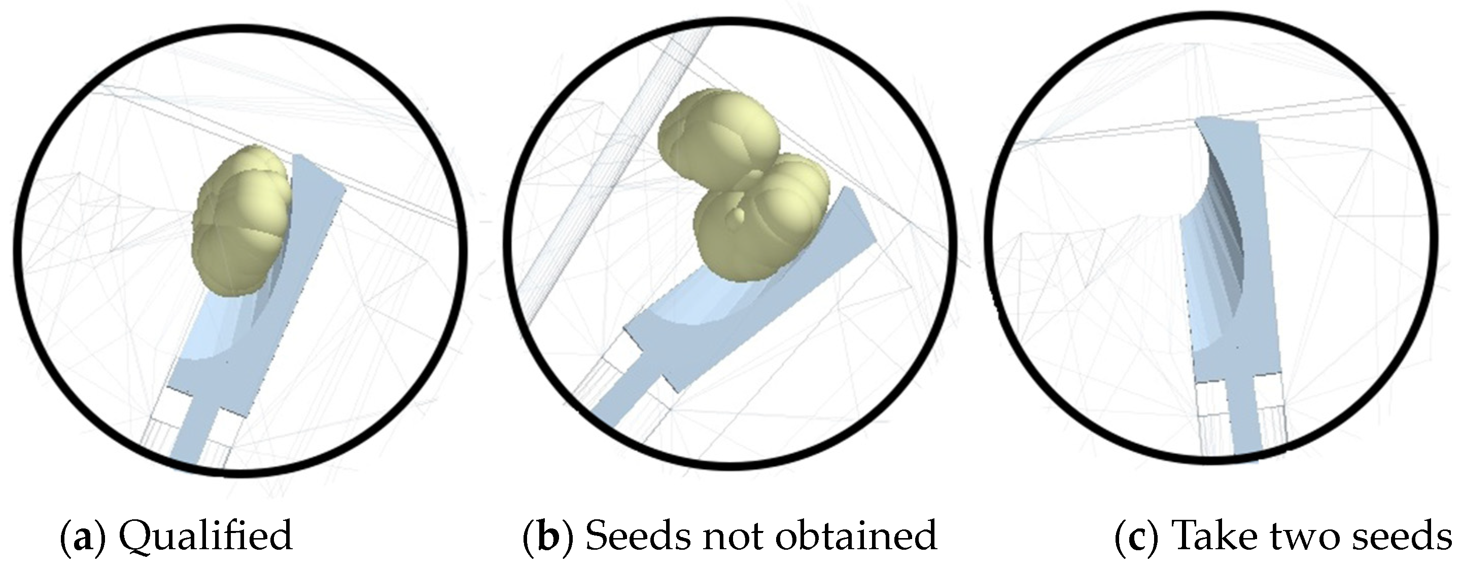
With the help of the simulation platform for the seed extraction process, we found that the seeds near the edge of the seed tray in the rising zone had the most similar speed to the seed tray, which is an important factor for successful seed extraction. The main cause of leakage was the “hitching arch” of the seed, and a targeted solution to break the arch by oscillating the seed pick-up slider was proposed.
(3)
A three-factor, three-level Box–Behnken central combination simulation test was conducted and the results were optimized. The optimum combination of parameters was obtained as follows: diameter of the outer edge of the gravity ring, 174.3 mm; installation angle of the block, 131.9°; and speed of the hole seeder, 85.2 rpm. The optimal combination of parameters was rounded off, and a test rig was built for validation. The test results show that, under the optimal parameter combination, the active clamped hole seeder had a seeding qualification index of 93.29%, re-seeding index of 1.06%, and leakage index of 5.65%, meeting the requirements for precision seeding.

10. Patents

The work reported in this manuscript is the subject of an application for a national patent for an invention entitled: An Active Clamping-Type Hole Planter for Rapid Seed Discharge of Irregular Seeds, Application No.: 202310818999X, Bulletin Publication No.: CN116830860 A, and the case status is: Awaiting Proposal for Substantial Examination.

Author Contributions

Methodology, J.M.; software, J.W. and X.X.; validation, X.L.; investigation, J.M. and S.S.; resources, B.H.; formal analysis, J.M.; data curation, J.M. and S.S.; writing—original draft preparation, J.M. and S.S.; writing—review and editing, B.H.; supervision, B.H.; funding acquisition, B.H. All authors have read and agreed to the published version of the manuscript.

Funding

This research was funded by the National Natural Science Foundation of China (grant no. 52165036).

Institutional Review Board Statement

Not applicable.

Data Availability Statement

Data associated with this research are available and can be obtained by contacting the corresponding author upon reasonable request.

Acknowledgments

The authors thank Xuewen Fu for his help in adjusting the camera during the experiment.

Conflicts of Interest

The authors declare no conflicts of interest.

References

  1. Yang, L.; Yan, B.; Zhang, D.; Zhang, T.; Wang, Y.; Cui, T. Research Progress on Precision Planting Technology of Maize. Trans. Chin. Soc. Agric. Mach. 2016, 47, 38–48. [Google Scholar]
  2. Liu, Z.Y.; Xia, J.F.; Liu, G.Y.; Cheng, J.; Wei, Y.S.; Xie, D.Y. Design and Analysis of a Pneumatic Automatic Compensation System for Miss-Seeding Based on Speed Synchronization. Agriculture 2023, 13, 1232. [Google Scholar] [CrossRef]
  3. Zhao, H.H.; Zhang, D.X.; Yang, L.; Cui, T.; Song, W.; He, X.T.; Dong, J.Q. Optimal design and experiment of critical components of hand-pushing corn plot precision planter. Agriculture 2022, 12, 2103. [Google Scholar] [CrossRef]
  4. Zhang, X.; Cheng, J.; Shi, Z.; Wang, M.; Fu, H.; Wu, H. Simulation and Experiment of Seed Taking Performance of Swing-clamp Type Maize Precision Seed-metering Divice. Trans. Chin. Soc. Agric. Mach. 2023, 54, 38–50. [Google Scholar]
  5. Dong, J.; Gao, X.; Zhang, S.; Huang, Y.; Zhang, C. Design and Test of Guiding Seed Throwing Mechanism for Maize Posture Control and Driving Metering Device. Trans. Chin. Soc. Agric. Mach. 2023, 54, 25–34. [Google Scholar]
  6. Geng, D.; Zhang, M.; He, K.; Li, Y.; Xie, C. Design and Experiment of Declined Disc Plate with Double Ring Corn Metering Device. Trans. Chin. Soc. Agric. Mach. 2018, 49, 68–76. [Google Scholar]
  7. Wang, J.; Tang, H.; Wang, J.; Li, X.; Huang, H. Optimization design and experiment on ripple surface type pickup finger of precision maize seed metering device. Int. J. Agric. Biol. Eng. 2017, 10, 11. [Google Scholar]
  8. Yang, L.; Yan, B.; Zhang, D.; Zhang, T.; Cui, T. Research progress on precision planting technology of maize. Transactions of the Chinese Society for Agricultural Machinery. 2016, 10, 801. [Google Scholar]
  9. Wang, L.; Zheng, Z.; Yu, Y.; Liu, T.; Zhang, Z. Determination of the energetic coefficient of restitution of maize grain based on laboratory experiments and dem simulations. Powder Technol. 2020, 362, 645–658. [Google Scholar] [CrossRef]
  10. Zhao, Z.; Li, Y.; Chen, Y.; Liang, Z.; Liu, L. Impact Mechanical Characteristics Analysis of Rice Grain. Trans. Chin. Soc. Agric. Mach. 2013, 44, 88–92. [Google Scholar]
  11. Guo, J.; Yang, Y.; Memon, M.S.; Tan, C.; Wang, L.; Tang, P. Design and simulation for seeding performance of high-speed inclined corn metering device based on discrete element method (dem). Sci. Rep. 2022, 12, 19415. [Google Scholar]
  12. Horabik, J.; Parafiniuk, P.; Wiacek, J.; Kobylka, R.; Molenda, M.; Stasiak, M. Dem modelling of the influence of initial stress state on the discharge rate of spherical particles from a model silo. Powder Technol. Int. J. Sci. Technol. Wet Dry Part. Syst. 2022, 403, 117402. [Google Scholar] [CrossRef]
  13. Fu, H.; Zhang, X.; Shi, Z.; Cheng, J.; Wu, H.; Wang, M.; Yu, Y. Design and test of maize precision seeder with seed-disturbance and side-filling slotted disk. J. Huazhong Agric. Univ. 2023, 42, 229–239. [Google Scholar]
  14. Hu, B.; Cai, Y.; Luo, X.; Mao, Z.; Li, J.; Guo, M.; Wang, J. Theory and experiment of high-speed seed filling in limited gear-shaped side space based on seeds group stress. J. Jilin Univ. (Eng. Technol. Ed.) 2022, 1–13. [Google Scholar] [CrossRef]
  15. Rahul, K.; Raheman, H.; Paradkar, V. Design and development of a 5r 2dof parallel robot arm for handling paper pot seedlings in a vegetable transplanter. Comput. Electron. Agric. 2019, 166, 105014. [Google Scholar] [CrossRef]
  16. Jia, H.; Chen, Y.; Zhao, J.; Wang, J.; Guo, M.; Zhuang, J. Design and Experiment of Pneumatic-mechanical Combined Precision Metering Device for Soybean. Trans. Chin. Soc. Agric. Mach. 2018, 49, 75–86. [Google Scholar]
  17. Cai, Y.Q.; Luo, X.; Hu, B.; Mao, Z.B.; Li, J.W.; Guo, M.Y.; Wang, J. Theoretical and experimental analyses of high-speed seed filling in limited gear-shaped side space of cotton precision dibbler. Comput. Electron. Agric. 2022, 200, 107202. [Google Scholar] [CrossRef]
  18. Kang, Q.; Zhang, G.; Zheng, K.; Liu, H.; Tang, N.; Liu, W.; Ji, C. Design and experiment of the spoon clip type seed metering device for Allium chinense. Trans. Chin. Soc. Agric. Eng. 2023, 39, 15–25. [Google Scholar]
  19. Vazquez, G.H.; Arf, O.; Sargi, B.A.; Pessoa, A.C.O. Corn seed size and shape influence on plant growth and grain yield. Biosci. J. 2012, 28, 16–24. [Google Scholar]
  20. Horabik, J.; Molenda, M. Parameters and contact models for DEM simulations of agricultural granular materials: A review. Biosyst. Eng. 2016, 147, 206–225. [Google Scholar] [CrossRef]
  21. Chen, Z.; Wassgren, C.; Veikle, E.; Ambrose, K. Determination of material and interaction properties of maize and wheat kernels for DEM simulation. Biosyst. Eng. 2020, 195, 208–226. [Google Scholar] [CrossRef]
  22. Markauskas, D.; Ramírez-Gómez, Á.; Kačianauskas, R.; Zdancevičius, E. Maize grain shape approaches for DEM modelling. Comput. Electron. Agric. 2015, 118, 247–258. [Google Scholar] [CrossRef]
  23. Cao, C.; Xiang, W.; Luo, K.; Wu, Z.; Zhang, X.; Qin, K. Design and Experiment of Radix Peucedani Weeding Machine Separating Weeds and Soil with Combination of Throwing and Pushing. Trans. Chin. Soc. Agric. Mach. 2023, 54, 106–114. [Google Scholar]
  24. Cao, C.; Ding, W.; Liu, Z.; An, M.; Zhang, X.; Qin, K. Design and Experiment of Seed Disperser for Ning-guo Radix peucedani Based on Rocky Dem. Trans. Chin. Soc. Agric. Mach. 2023, 54, 53–64. [Google Scholar]
  25. Cao, C.; Liu, Z.; Ding, W.; Wu, M.; Zhang, X. Design and Experiment of Ning-guo Radix Peucedani Bionic Digging Shovel. Trans. Chin. Soc. Agric. Mach. 2023, 54, 11. [Google Scholar]
  26. Shi, L.; Zhao, W.; Yang, X. Effects of typical corn kernel shapes on the forming of repose angle by DEM simulation. Int. J. Agric. Biol. Eng. 2022, 15, 248–255. [Google Scholar] [CrossRef]
  27. GB/T1593-2015; Agricultural Wheeled Tractor—Rear-Mounted Three-Point Linkage—Categories 0, 1N, 1, 2N, 2, 3N, 3, 4N and 4. China Standard Press: Beijing, China, 2015.
  28. JB/T 10293-2001; Specifications of Single Seed Drill (Precision Drill). Institute of Mechanical Science: Beijing, China, 2001.
  29. Ma, C.; Yi, S.; Tao, G.; Li, Y.; Wang, S.; Wang, G.; Gao, F. Research on Receiving Seeds Performance of Belt-Type High-Speed Corn Seed Guiding Device Based on Discrete Element Method. Agriculture 2023, 13, 1085. [Google Scholar] [CrossRef]
  30. Shi, L.; Zhao, W.; Hua, C.; Rao, G.; Guo, J.; Wang, Z. Study on the Intercropping Mechanism and Seeding Improvement of the Cavity Planter with Vertical Insertion Using DEM-MBD Coupling Method. Agriculture 2022, 12, 1567. [Google Scholar] [CrossRef]
  31. Liu, R.; Liu, L.; Li, Y.; Liu, Z.; Zhao, J.; Liu, Y.; Zhang, X. Numerical simulation of seed-movement characteristics in new maize delivery device. Agriculture 2022, 12, 1944. [Google Scholar] [CrossRef]
Figure 1. Schematic diagram of the structure of the active clamping-type corn precision hole planter: 1. Seed intake tube. 2. Finalized disc. 3. Seed-picking disc assembly. 4. Seed-cleaning brushes. 5. Seed cavity. 6. Platen. 7. Toggle seed spring. 8. Seed discharge module assembly. 9. Axle. 10. Rotating disc. 11. Seed extraction tray. 12. Seed extraction slider. 13. Retainer block. 14. Gravity ring. 15. Connecting rod.
Agriculture 14 00398 g001
Figure 2. Dividing the working area of the hole planter.
Agriculture 14 00398 g002
Figure 3. Geometric shape of the corn seeds.
Agriculture 14 00398 g003
Figure 4. Analysis of the cross-sectional shape of the combined-type holes. Note: x and y indicate the axis before rotation; x1 and y1 represent the axis after counterclockwise rotation of θ; a and b are the long and short axes of the ellipse, mm; h is the combined hole depth, mm; W1, W2, D1, D2, H, and T are the statistical dimensions of the seeds, respectively, mm; k is the slope corresponding to the angle θ, tan θ = k; and σ is the standard deviation of the corresponding size.
Agriculture 14 00398 g004
Figure 5. Simplified hydrostatic model of seed extraction disc assembly. Note: L1 is the distance from the center of the stopper to the center of the seed-taking disc, mm; R is the radius of the inner edge of the gravity ring, mm; r is the block radius, mm; h is the vertical distance between the center of the seed extraction disc and the center of the gravity ring, mm; ψ is the acute angle between the line joining the center of the gravity ring and the center of the block and the y-axis, rad; and θ is the acute angle between the center of the block and the center of the gravity ring and the y-axis, rad; b is the distance from the origin of the coordinate axis to the outer edge of the gravity ring, mm; e is the distance moved by the seeding slider, mm.
Agriculture 14 00398 g005
Figure 6. Distance of the seeding slide relative to the center of rotation.
Agriculture 14 00398 g006
Figure 7. Analysis of forces on the seed-guiding surface. Note: θ is the inclination angle of the seed-guiding surface, °; δ is the number of radians of the circular angle made by the center of gravity of the seed and the center of the arc, rad; Fn is the support force of the seed on the guiding surface, N; f1 is the friction force between populations, N; f2 is the friction force between the seed and the side wall of the seed-holding chamber, N; f3 is the friction force on the seed-guiding surface, N; F1 is the support force, N, of the lower seed on the upper seed; Fr is the centrifugal force of the seed, N; and G is the gravitational force on the seed, N.
Agriculture 14 00398 g007
Figure 8. (a) Seed acceleration on the seed-guiding surface. (b) Acceleration rate of change curve.
Agriculture 14 00398 g008
Figure 9. Combined-type hole structure. 1. Seed-guiding surface. 2. Seed-holding surface. 3. Chunky surface. 4. End face.
Agriculture 14 00398 g009
Figure 10. Thrust curve of seed-guiding surface.
Agriculture 14 00398 g010
Figure 11. Relationship between the disc rotation angle and the position of the centroid angle of the seed-guiding surface.
Agriculture 14 00398 g011
Figure 12. Velocity profile of seed movement.
Agriculture 14 00398 g012
Figure 13. Analysis of the seed-feeding process. Note: A plane rectangular coordinate system was established with the center of mass o of the seed as the origin and the tangent direction of rotation of the seed extraction disc as the X-axis. The red line indicates the trajectory of the center of mass of the corn seed.
Agriculture 14 00398 g013
Figure 14. Force analysis of the seed in the hole. Note: Ff is the friction force between the combinatorial pore and the seed, N; Fhx and Fhy are the horizontal and vertical component forces on the selected seeds from the population [18], N; Fn is the support force of the combined type of hole on the seed, N; μ is the static friction factor between the seed and the combined pore material; and Fr is the centrifugal force of inertia on the selected seeds, N.
Agriculture 14 00398 g014
Figure 15. Simulated filling of grains.
Agriculture 14 00398 g015
Figure 16. Combined-hole seeding situation.
Agriculture 14 00398 g016
Figure 17. Monitoring area of seed picking.
Agriculture 14 00398 g017
Figure 18. Seed-picking performance curve.
Agriculture 14 00398 g018
Figure 19. Corresponding surfaces for the interaction of factors on seed-taking performance.
Agriculture 14 00398 g019
Figure 20. Bench experiment of the seed tray. 1. Corn seed. 2. Seedbed belt. 3. Seed-taking disc. 4. Combined-type holes. 5. Active clamping-type corn precision hole planter. 6. Digital camera.
Agriculture 14 00398 g020
Table 1. Three types of corn seed parameters and their distribution.
TypeRelevant Parameters (mm)Percentage
aOverall width (W1)Lower width (W2)Above average (H)Thicker (T)
7.158.9211.574.4347.6%
bOverall diameter (D1)Lower diameter (D2)Above average (H)
6.27811.14 23.8%
cCaliber (D)
5.5 28.6%
Table 2. EDEM simulation parameters.
CornPoisson’s ratio
Young’s modulus/MPa
Serrated particle density/kg·m−3
Spherical and conical particle density/kg·m−3
Quasi-spherical particle density/kg·m−3
Collision recovery coefficient
Static friction coefficient
0.4
26
1213
1194
1234
0.37
0.2
[20]
[20]
Determine
Determine
Determine
[21]
[22]
PLAPoisson’s ratio
Shear modulus/Pa
Density/kg·m−3
0.35
3 × 10⁹
1240
[23]
[24]
[25]
SteelPoisson’s ratio
Shear modulus/Pa
Density/kg·m−3
0.3
7.9 × 10¹⁰
7800
EDEM self-contained materials
Corn and PLACollision recovery coefficient
Static friction coefficient
Coefficient of rolling friction
0.45
0.85
0.05
Determine
Determine
Determine
Corn and SteelCollision-recovery coefficient
Static friction coefficient
Coefficient of rolling friction
0.5
0.32
0.01
[26]
Determine
[26]
Table 3. Coding table of factor level.
LevelsFactors
The Diameter of the Outer Edge of the Gravity Ring X1/mmThe Angle of the Block Installation X2The Speed of the Hole Planter X3/rpm
−117212560
017413584
1176145108
Table 4. Test results.
Experiment FactorsExperiment Indexes
NumberThe Diameter of the Outer Edge of the Gravity Ring X1/mmThe Angle of the Block Installation X2The Speed of the Hole Planter X3/rpmQualified
Index
A
Replay
Index
D
Leakage
Index
M
117293.66091.153.855
217693.66094.365.640
31721176079.12.8218.08
41761176092.694.752.56
5172105.34574.492.3123.2
6176105.34589.113.727.17
7172105.37591.2853.72
8176105.37592.847.050.11
917493.64585.643.4610.9
101741174576.413.0720.52
1117493.67593.466.40.14
121741177592.955.391.66
13174105.36092.443.723.84
14174105.36091.933.854.22
15174105.36093.723.972.31
16174105.36094.613.981.41
17174105.36092.33.723.98
Table 5. Design and results of Box–Behnken experiment.
SourceQualified Index A (%)Leakage Index D (%)
Sum of SquaresdfF-Valuep-ValueSum of SquaresdfF-Valuep-Value
Module646.72952.71<0.0001 **26.98988.44<0.0001 **
X1130.98195.09<0.0001 **7.411218.67<0.0001 **
X274.12153.810.0002 **0.845124.930.0016 **
X3249.981181.50<0.0001 **16.361482.67<0.0001 **
X1×220.52114.900.0062 **0.5929117.490.0041 **
X1X342.45130.820.0009 **0.0912.660.1472
X2X318.71113.580.0078 **0.078412.310.1721
X1218.62113.520.0079 **0.3789111.180.0124 *
X2215.65111.360.0119 *0.6906120.380.0028 **
X3265.71147.10.0002 **0.3664110.810.0133 *
Residual9.647 0.03397
Lack of fit4.7431.290.39280.165933.10.1517
Pure error4.904 0.07144
Cor total656.3616 27.2116
SourceReplay index M (%)
Sum of squaresdfF-valuep-value
Module856.01968.8<0.0001 **
X1200.71145.18<0.0001 **
X290.79165.67<0.0001 **
X3394.241285.19<0.0001 **
X1X228.09120.320.0028 **
X1X338.63127.940.0011 **
X2X316.36111.840.0108 *
X1213.6919.90.0162 *
X229.7717.060.0326 *
X3256.26140.70.0004 **
Residual9.687
Lack of fit3.9230.90920.5116
Pure error5.754
Cor total27.2116
Note: * significant (p < 0.05), ** extremely significant (p < 0.01).
Table 6. Test validation results.
Test NumberQualified Index (%)Replay Index (%)Leakage Index (%)
193.625.650.37
292.896.120.99
393.365.201.44
Average value93.295.651.06
Disclaimer/Publisher’s Note: The statements, opinions and data contained in all publications are solely those of the individual author(s) and contributor(s) and not of MDPI and/or the editor(s). MDPI and/or the editor(s) disclaim responsibility for any injury to people or property resulting from any ideas, methods, instructions or products referred to in the content.

