Article

Design and Testing of a Pleurotus pulmonarius Stick Cutting Machine

1
College of Engineering and Technology, Southwest University, Chongqing 400715, China
2
Key Laboratory of Agricultural Equipment in Hilly and Mountainous Areas, Southwest University, Chongqing 400715, China
3
School of Mechanical and Eletrical Engineering, University of Electronic Science and Technology of China, Chengdu 611731, China
*
Author to whom correspondence should be addressed.
These authors contributed equally to this work.
Agriculture 2024, 14(10), 1795; https://doi.org/10.3390/agriculture14101795
Submission received: 3 September 2024 / Revised: 25 September 2024 / Accepted: 26 September 2024 / Published: 12 October 2024
(This article belongs to the Section Agricultural Technology)

Abstract

:
Based on the cultivation environment and material parameters of Pleurotus pulmonarius sticks, a P. pulmonarius stick cutting machine is designed to solve the problem of directly realizing the cutting of P. pulmonarius sticks for a net-shaped mushroom stick cultivation layer frame. The machine consists of three parts: a traveling trolley, an XYZ three-axis moving mechanism, and a clamping and cutting mechanism. Based on the force analysis of the clamping and cutting mechanism and the P. pulmonarius sticks, the key components were designed and selected. A prototype was constructed, and several cutting tests were conducted, with the cutting speed, number of cutting circles, and depth of the cut as the main factors. The success rate of cutting, the roundness of the cut, and the degree of loss in terms of the cutout substrate, were used as the performance indicators. An optimized design, based on orthogonal testing, was employed to determine the optimal parameter combinations for the cutting process. The optimal parameters were found to be a cutting speed of 376.3 r/min, 5.4 cutting circles, and a cutting depth of 4 mm. Finally, a validation test was carried out on the machine, and the results show that under the same parameter conditions, the success rate of cutting was 86.6%, the roundness of the cut was 0.235, and the degree of loss in terms of the cutout substrate was 0.851%, which is consistent with the optimization results. This study provides a reference, including a practical reference, for the design and development of a machine to realize the cutting of P. pulmonarius sticks for a cultivation layer frame.

1. Introduction

Pleurotus pulmonarius, also known as the pocket mushroom, the lung-shaped sidearm, the phoenix-tailed mushroom, and the Himalayan flat mushroom [1], is small in size, but has crunchy flesh and a delicious flavor, and is rich in nutrition, containing a variety of beneficial trace elements, proteins, amino acids, and polysaccharides, and other biologically active compounds [2,3]; it has immunomodulatory, anti-tumor, anti-oxidation, anti-aging, and nervous system-protection properties, and other medicinal value [4,5,6].
China is the world’s largest producer, consumer, and exporter of edible mushrooms [7]; according to the China Edible Mushroom Association, in 2022, the total output value of edible mushrooms in China was CNY 388.722 billion, and the total output has reached 4.22253 × 10 2 billion tons, accounting for more than 80% of the world’s global production of edible mushrooms. The output of P. pulmonarius, as one of the main varieties of edible mushrooms in China, ranks among the top ten in terms of the national total output of edible fungi [8].
Long-stick substitute cultivation is the primary method used for the factory cultivation of edible mushrooms in China [9]. Unlike other cultivation methods, this approach requires the cutting and opening of the bags containing the mushroom sticks [10]. The purpose of cutting and opening the bag is to create an opening that increases the aeration for the mushroom body, allowing the mushrooms to emerge from the cut. As a crucial part of the edible mushroom production process, cutting and opening the mushroom stick bags is still largely conducted manually, which makes it difficult to meet the demands of factory production. Therefore, research and development on mushroom stick cutting machine is of great significance to reduce the labor required, improve the production efficiency, reduce the production cost, and improve the degree of mechanization within the edible mushroom industry.
There are only a few international reports on the research into cutting technology and equipment for P. pulmonarius cultivation, and domestic research on P. pulmonarius stick cutting technology started relatively recently. Currently, the research on opening mushroom stick bags primarily focuses on breaking and removing the bags, with the cutting target typically located on the cylindrical side of the sticks. And there is a gap in the research on the process of opening the bags, in terms of the area at the end of the P. pulmonarius sticks that needs to be cut open. For example, Wang Xinjing [11] designed a kind of fungus stick with more than one single notcher related to automatic notching equipment, the notching position of which was focused on the cylindrical side of the fungus sticks. The equipment requires two people to operate: one person places the fungus sticks into the notching equipment, while the other stands at the back end of the equipment to receive and place the notched fungus sticks into the fungus frame. This process enables the automatic, uniform notching of the fungus sticks during transfer. Ma Shixin [12] researched and designed a mushroom stick separator with three breaking mechanisms: a horizontal cutting mechanism, a vertical cutting mechanism, and a turning ring cutting mechanism. The machine first positions the sticks and then comprehensively breaks the outer packaging bag of the mushroom sticks that are put into the machine as a result of several steps, such as vertical cutting, horizontal cutting, and rotating cutting, in order to prepare for the subsequent de-bagging process; the process first realizes the automated bag–stick separation integration operation involving the mushroom sticks. Liu Jingyu [13] from Shanxi Agricultural University and other researchers designed a bagging machine for edible mushroom sticks, which has a longitudinal cutter and a ring cutter for the cutting part of the machine, and when it works, it uses a straight-line push to drive the sticks through the longitudinal cutter and the ring cutter, so as to cut open the bags of the sticks; the machine is also a single stationary device, and it is necessary to put the sticks into the device for the bag cutting operation to be successful. Liu Yan [14] and other researchers designed a fiber bag cutting machine; the bag cutting parts of the machine include a bottom bag cutting device and a side bag cutting device. During operation, the sawtooth knife, as part of the bottom bag cutting device, and the linear drive knife, as part of the side bag cutting device, work at the same time, to achieve the movement of the fiber package during the process of cutting the fiber package, and these authors were the first to achieve the automation of fiber package bag cutting. In summary, the cutting parts of the existing notching equipment are used in a single stationary machine. When using a single piece of stationary equipment to cut and open a bag of mushroom sticks on the cultivation layer rack, significant manual labor is required. Workers must move the mushroom sticks down from the rack, place them into the cutting equipment, and then return the cut sticks to the rack. This process is labor-intensive and time-consuming, making it difficult to reduce production costs [15].
To address the aforementioned issue, drawing on the research methods of relevant scholars, this paper developed a self-propelled cutting device capable of cutting the end face of P. pulmonarius sticks on a grid cultivation layer frame, significantly reducing the level of manual participation in the cutting and bag-opening process. The feasibility of the P. pulmonarius stick cutting machine was validated through a combination of theoretical guidance and experimental analyses.

2. Materials and Methods

2.1. Design of a Pleurotus pulmonarius Stick Cutting Machine

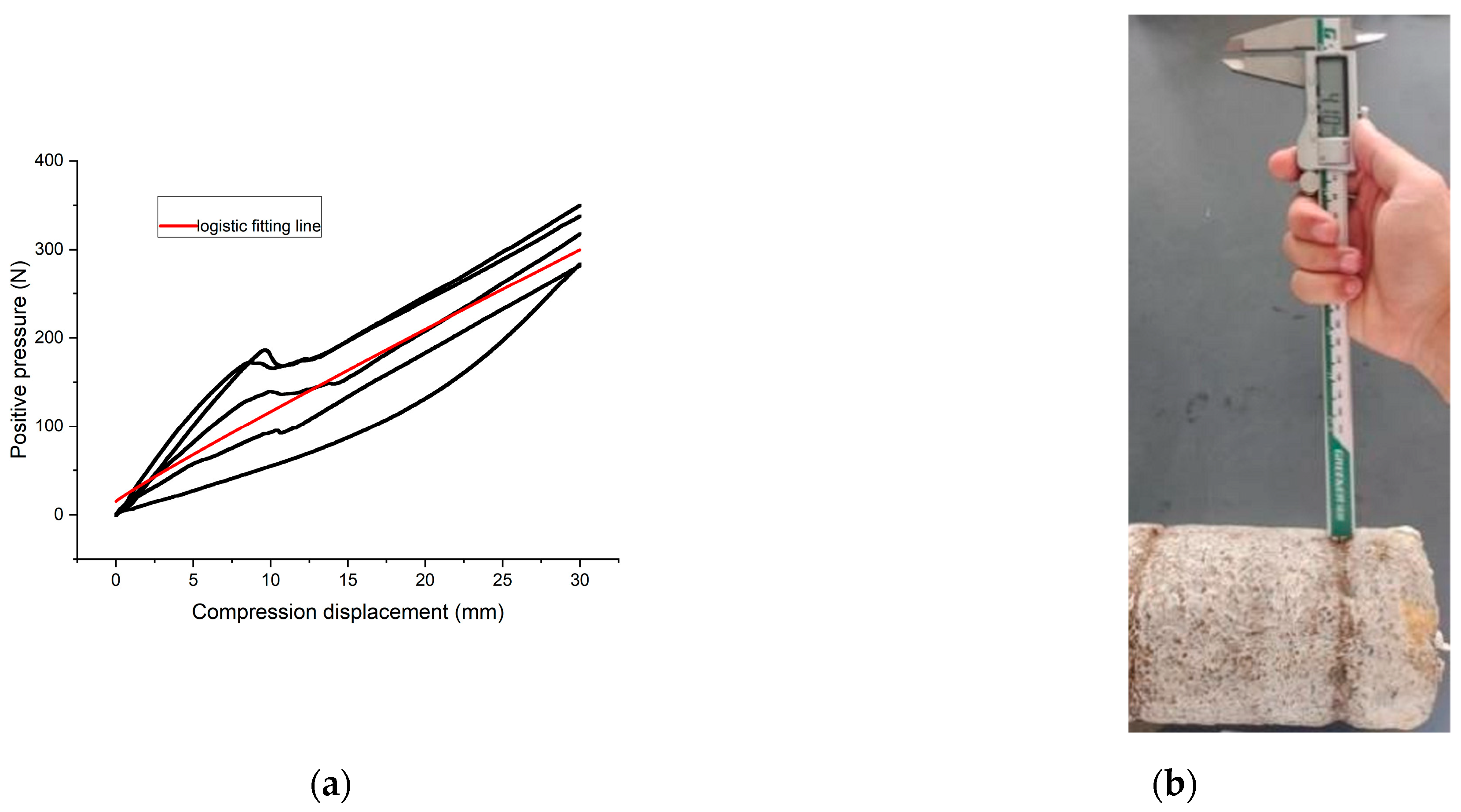
2.1.1. Cultivation Environment and Material Parameters of P. pulmonarius Sticks

In this study, P. pulmonarius sticks in good growth condition, fully developed, free of pests and diseases, and with no visible defects, were selected as the test objects. The sticks (including the outer packaging bag, substrate, and ring) were placed in a stainless steel mesh format cultivation layer rack, as shown in Figure 1a. The rack consisted of multiple layers, with the grid edge slightly larger than the stick diameter. When the P. pulmonarius sticks show a rolling tendency, the contact steel wire of the mesh cultivation layer rack will exert a certain positive pressure on the sticks; compared with the traditional stacking arrangement, the sticks are placed in a more regular way using a grid format, with better ventilation and higher space utilization, which facilitates the implementation of mechanized cutting. On 8 April 2024, the physical parameters of the P. pulmonarius sticks were measured in a standardized mushroom room at Chongqing Fungus Easy Edible Mushroom Cultivation Company Ltd., located in Hegeng Town, Yongchuan District, Chongqing, China (Coordinates: 105°37′37″~106°05′06″ E, 28°56′16″~29°34′23″ N). With reference to the national standard GB/T 5262-2008 [16], “General Provisions on Determination Methods for Test Conditions of Agricultural Machinery”, the outer packaging material of P. pulmonarius sticks was polypropylene, with a thickness of 0.05 mm, and 10 sticks were randomly selected from the cultivation shelf in the mushroom house, with reference to the diameter of the stick d 1 , the ring diameter d 2 , the overall height of the fungus h 1 , the height of the fungus pocket from the bottom h 2 , the height of the fungus cylinder h 3 and the mass of the fungus m . The parameter measurements are shown in Figure 1b, and the morphological parameters are presented in Table 1.
The P. pulmonarius stick cutting machine developed in this paper is designed for the O-shaped cutting of the front end of P. pulmonarius sticks on a grid-format cultivation rack. The cut plane is shown in Figure 1b, and is located in the p-plane of the stick, while the diameter of the cut is slightly smaller than the diameter of the P. pulmonarius stick by 1 cm. During the notching process, the wire mesh exerts a certain positive compressive force on the sticks to stop the rolling of the sticks.
Additionally, the tensile properties of the polypropylene bags and the resistance encountered by the cutter when cutting into the substrate of the P. pulmonarius sticks were tested using a universal testing machine (model: CMT5105GD, maximum load 1 × 10 5 N, accuracy class 0.5), as shown in Figure 2a,b. After several sets of repeated tests, the tensile yield force of the bag was measured to be 23.0 N, the breaking force was approximately 24.5 N and the resistance of the blade cutting into the substrate of 5 mm was 6 N.

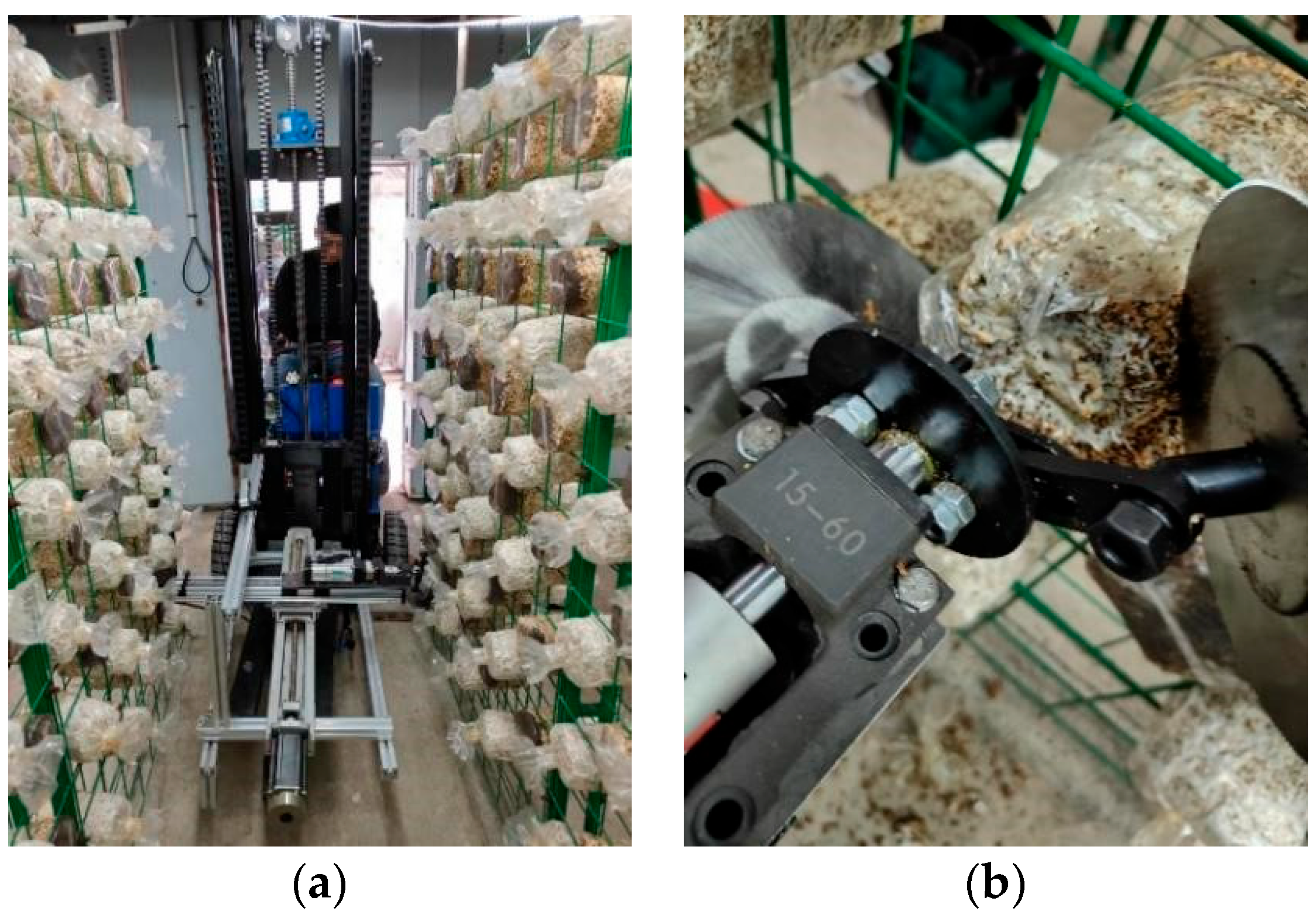
2.1.2. Overall Structure and Working Principle of Stick Cutting Machine

According to the cultivation environment and material parameters of P. pulmonarius sticks, the designed P. pulmonarius stick cutting machine mainly consists of a travelling trolley, an XYZ three-axis moving mechanism, a clamping and cutting mechanism, a binocular camera, a frame, and a control box, as shown in Figure 3a,b.
To achieve the autonomous operation of the P. pulmonarius stick cutting machine, the visual recognition system, control system, moving mechanism, and clamping and cutting mechanism were set up to perform the joint cutting operation. The cutting mode was designed to be an integrated operation mode of ‘recognition–calculation–movement–notching’. The vision system identifies and locates the P. pulmonarius stick, while the control system plans the trajectory and guides the XYZ three-axis movement mechanism to position the clamping and cutting mechanism from the reference point to the spatial coordinates of the stick’s center for cutting. After each cut, the clamping and cutting mechanism, along with the Y-axis movement mechanism, resets in preparation for the next stick. This cycle repeats until all planned cutting tasks are completed.

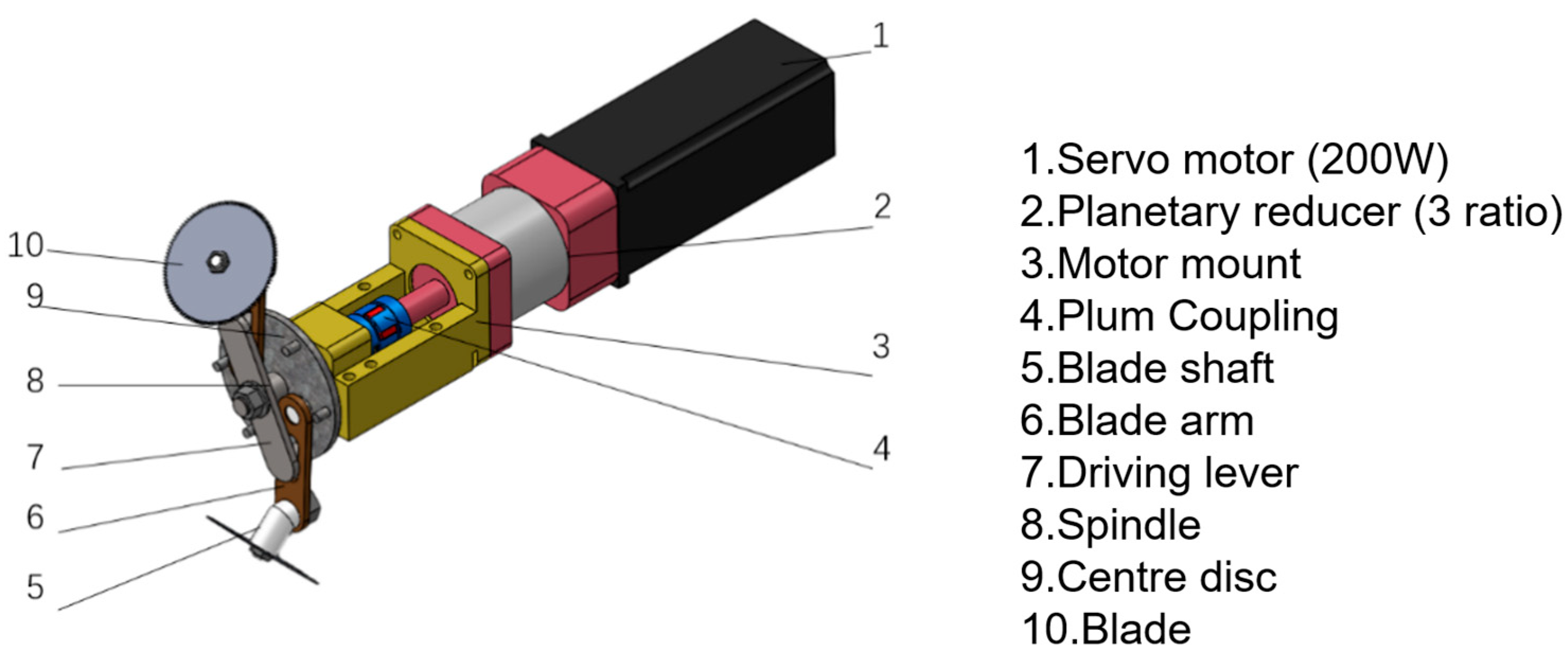
2.1.3. Structure and Working Principle of End-Effector Clamping and Cutting Mechanism

The P. pulmonarius stick’s clamping and cutting mechanism is shown in Figure 4, and its main parts include a spindle, a center disc, a cutter arm, a cutter arm pin, a driving lever, a cutter shaft, a cutter, a servo motor (Manufacturer: Change to: Shenzhen Huakexing Technology Co., Shenzhen, China), a planetary reducer (Manufacturer: Change to: Shenzhen Huakexing Technology Co.) and other components.
In the design of the clamping and cutting mechanism, the driving lever and blade arm are symmetrically arranged in the circumferential direction with two groups of two-bar mechanisms, and each group of two-bar mechanisms shares a set of spindles and a center disc.
In the initial state, the blade arm leans against the limit p 1 column of the central disc. At this point, the internal distance between the two blades exceeds the diameter of the P. pulmonarius stick, allowing the P. pulmonarius stick to enter the gap between the two blades, as shown in Figure 5a. During the clamping process, the driving lever rotates clockwise, driving the lever to move inside the slots of the blade arm. At the same time, the blade arm moves closer to the limit p 2 column of the central disc, gradually reducing the inner distance between the two blades and clamping the outer outline of the front end of the P. pulmonarius stick at the p-plane of the mouth, as shown in Figure 5b. During the cutting process, the blade arm presses against the center disk p 2 ’s limit column, and the driving lever rotates the blade arm and the center disk clockwise along the arc s 1 direction. This causes the two blades to rotate along the outer contour of the front end of the P. pulmonarius stick, cutting through the front face of the bag, as shown in Figure 5c. The components are installed in conjunction with each other to increase the appropriate preload, ensuring tight connections, and in contact with each other to add a certain amount of lubrication so as to reduce the friction between them.

2.2. Mechanical Analyses during Cutting Operations

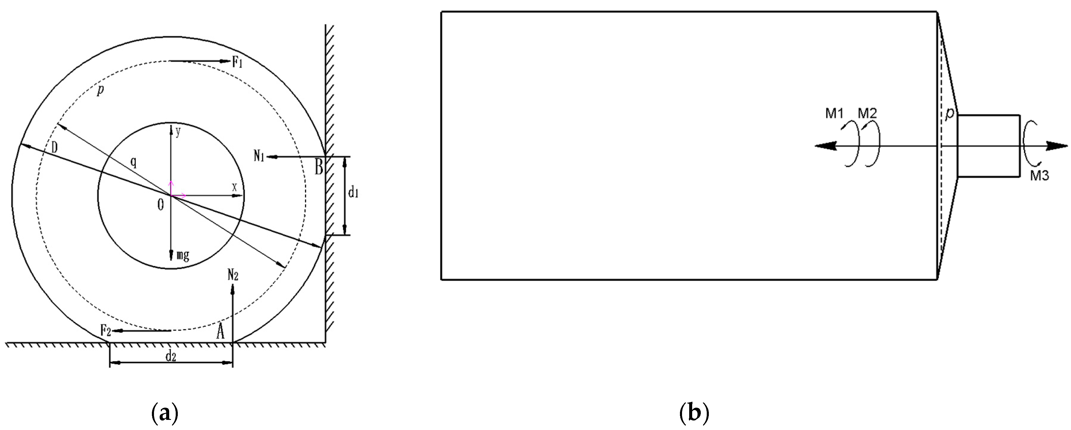
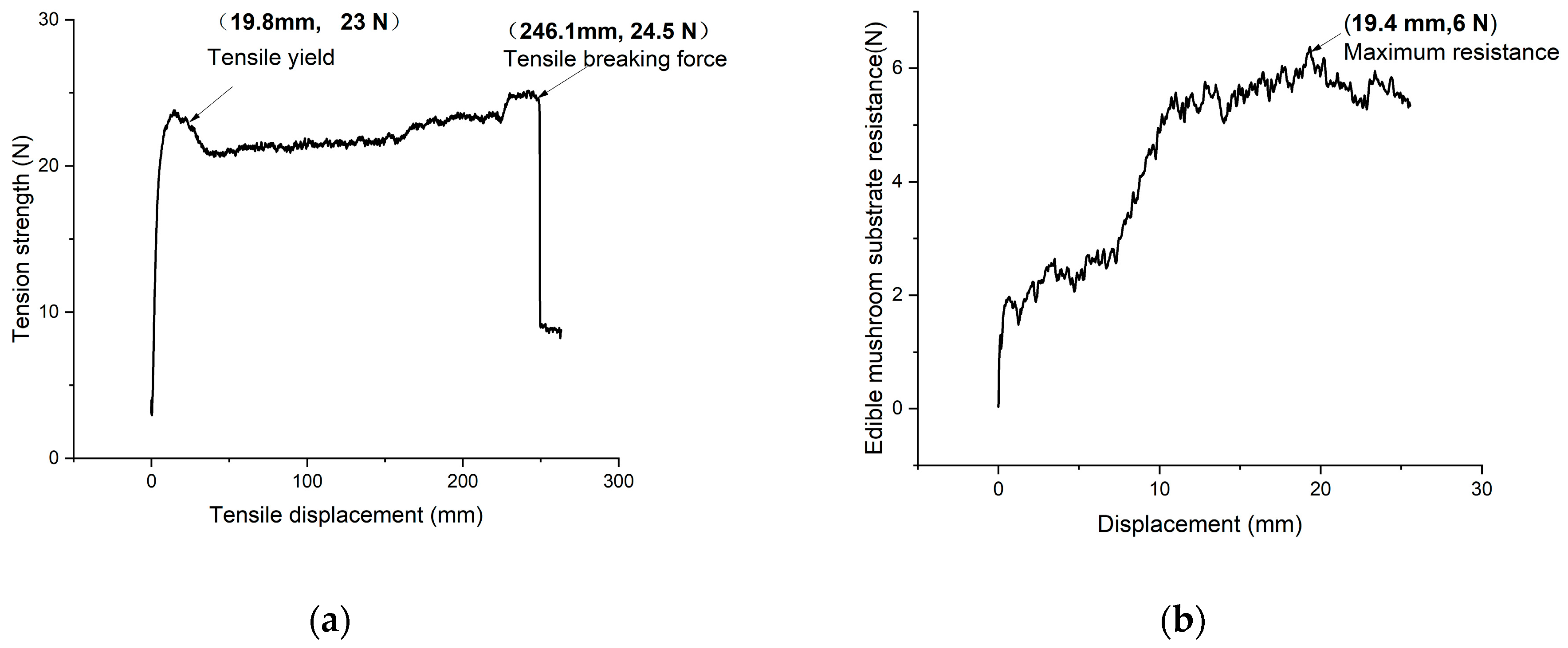
2.2.1. Force Analysis of P. pulmonarius Sticks

We first place the P. pulmonarius sticks to be cultivated on the right side of the grid of the growing layer rack, ensuring contact with four grid wires. The sticks must be cultivated on the growing rack in the mushroom room for 7–10 days before cutting. Due to gravity, the sticks will deform over time, causing the grid wires to embed at varying depths into the substrate of the P. pulmonarius sticks and forming four contact surfaces. The bottom wires of the grid create two contact surfaces, while the right-side wires create another two. Since the forces on the same side have the same magnitude and direction, these two contact surfaces on each side can be simplified into one. Research and investigation shows that, after the deformation of the P. pulmonarius stick, the average depth of the steel wire embedded in the substrate of the P. pulmonarius stick on the bottom side of the frame is about 5 mm, while the average depth of the steel wire embedded in the P. pulmonarius stick on the right side is about 1 mm. The trajectory of the two blades cutting the front of the P. pulmonarius stick in the clamping and cutting mechanism corresponds to the front profile of the P. pulmonarius stick where the p-plane is located, and the cutting force of two blades used to cut the P. pulmonarius stick is denoted as F 1 and F 2 , forming a pair of equal and opposite non-collinear forces, as shown in Figure 6a.
The force coupling arm length is q and the force coupling moment vector is M 3 ; when operated with the cutting forces F 1 and F 2 , the grid within the P. pulmonarius stick has a clockwise rolling tendency. The lower side of the P. pulmonarius stick and the right side of the force surface will be subjected to grid steel wire extrusion deformation; at this time, the steel wire placing positive pressure on the P. pulmonarius stick can be simplified as N 1 and N 2 . Due to the clockwise rolling tendency, the contact point on the lower side of the contact surface of the P. pulmonarius stick can be simplified to the end points A. On the right side of the contact surface, the force is simplified to the point of B; A and B are then the two points of positive pressure, and the moment of the rotation center is O for M 1 and M 2 , as shown in Figure 6b.
In order to determine the magnitude of the positive pressure exerted at points A and B, a compression test and a rolling bench test of the P. pulmonarius stick are required. Here, a flat plate indenter was used in the compression test, which was loaded at a loading speed of 100 mm/min, and the positive pressure–compression displacement curves obtained, a total of five tests were performed and averaged, as shown in Figure 7a. The rolling stand test of the P. pulmonarius stick was carried out in the new engineering test building of Southwest University, selecting 10 P. pulmonarius sticks according to the previous statistical data as the test objects, and using two blades symmetrically inserted into the substrate of the front surface of P. pulmonarius sticks at a sufficient depth. When the motor was rotating, the two blades provided the sticks sufficient circumferential torque to promote the rolling of the P. pulmonarius stick in the grid of the growing stand, and the indentation on the substrate of the P. pulmonarius stick was measured at the end of rolling, as shown in Figure 7b. According to the test, the average depth of the indentation left by the grid’s steel wire on the substrate of the P. pulmonarius stick was 4 mm when the stick was rolling, and the indentation was obvious. The positive pressure exerted by the steel wire of the cultivation frame on the P. pulmonarius stick during rolling was calculated to be N i   =   58.7   N .

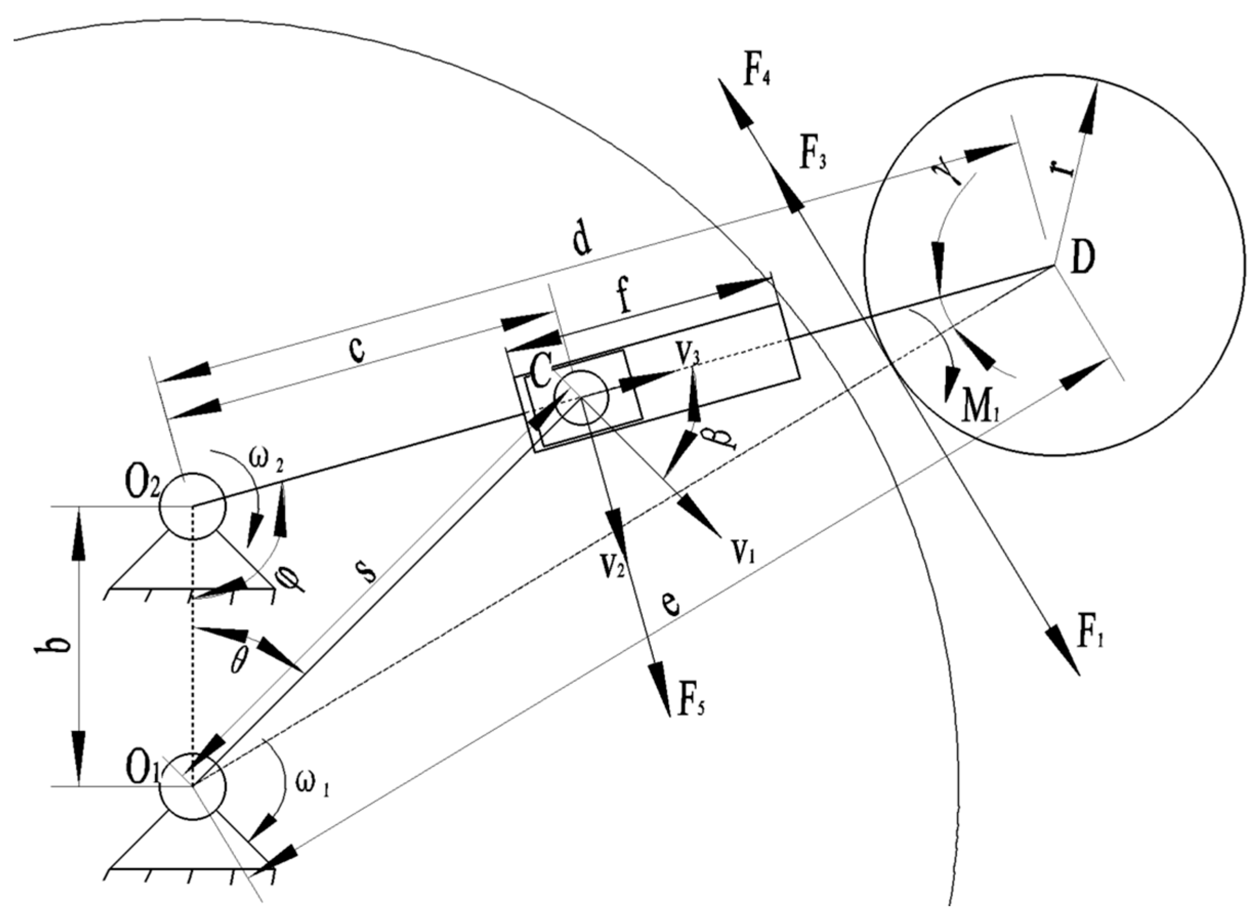
2.2.2. Clamping Cutting Mechanism Force Analysis and Key Components Selection

During the P. pulmonarius stick cutting operation, the output shaft of the motor shows a uniform circular motion, with a rotational angular velocity of ω 1 , and the rotational angular velocity of the blade arm is ω 2 .   F 1 is the cutting force of the blade used to cut the sticks, F 3 is the resistance given to the blade by the bag of sticks, F 4 is the resistance given to the blade by the substrate of the sticks, and F 5 is the force transmitted to the blade arm by the driving lever. Since the two blades of the clamping and cutting mechanisms are arranged symmetrically along the central axis, one side is taken for analysis [17], and the clamping and cutting mechanism is thus simplified. The motion analysis and force analysis are then carried out, as shown in Figure 8.
During the clamping process, the clamping and cutting mechanism drives the blade arms to symmetrically insert two blades at a specific angle into the front face of the stick substrate. The angle of rotation of the driving lever is θ , and the tangential speed of the driving lever B end is v 1 . The output torque of the servo motor is converted into the cutting force F 1 on the blade through the clamping and cutting mechanism, acting along the tangential direction of the blade and perpendicular to the O 2 C straight line. The blade cuts the upper end surface of the stick, with the resistance forces of the polypropylene stick bag and the stick substrate being F 3 and F 4 , respectively. The driving lever transfers to the blade arm (moving at the speed of v 2 perpendicular to the direction of the blade arm) the positive pressure of F 5 ; the driving lever slider B in the blade arm sliding groove has a sliding speed of v 3 .
By analyzing the geometric relationship of the clamping and cutting mechanism during the movement, as shown in Figure 8, we see that O 1 O 2 C , O 1 C D and O 1 O 2 D are
c 2   =   s 2   +   b 2 2 s b cos ω 1 t β   =   π 2 arccos [ s b cos ω 1 t c ] cos φ   =   b 2   +   c 2 s 2 2 b c e 2   =   b 2   +   d 2 2 b d cos φ γ   =   arccos ( d 2   +   e 2 b 2 2 d e )
where b is the distance between the center of rotation of the driving lever and the center of rotation of the blade cutter arm, mm; c is the distance between the center of the driving lever slider C and the center of rotation of t the blade arm O 2 at the moment t, mm; e   is the distance between the center of the blade D and the center of rotation of the driving lever O 1 at the moment t, mm; s is the radius of the driving lever, mm; r is the radius of the blade, mm; β is the angle between the direction of the tangential velocity v 1 of the driving lever and the blade arm O 2 D at time t, °; φ is the angle between O 1 O 2 and the blade arm O 2 D, °; γ   is the moment t in the direction of the blade arm O 2 D and the angle between the straight line O 1 D, °; ω 1 is the rotational angular velocity of the driving lever, r a d s 1 .
Here, b   =   20   m m , s   =   35   m m , θ     110 ° and r   =   6   m m are known design parameters; the diameter of the blade on the front face of the P. pulmonarius stick is about 1 cm smaller than the diameter of the P. pulmonarius stick, and so e   =   59   m m is taken. In the initial state, the inner spacing of the two blades is larger than the diameter of the P. pulmonarius stick, thus d   =   60   m m is taken. The above known parameters are substituted into Equation (1), resulting in the length of the blade arm slide groove being f   =   15   m m .
F 5   =   T s sin [ π 2 arccos ( s b cos ω 1 t s 2   +   b 2 2 s b cos ω 1 t ) ] F 1   =   F 5 × sin ( π 2 γ ) M 1   =   F 1 × ( e r )
where T is the rated torque of the motor, N m ; M 1 is the force-coupling moment of the cutting force, N m .
It can be seen from the formula that the size of F 1 is determined jointly by the parameters of the clamping cutting mechanism. In this study, a 200 W servo motor and a planetary reducer with a 3:1 ratio are used to rotate at ω 1   =   33.4 π   r a d s 1 at the rated angular speed, and the known parameters are brought into the above Equations (1) and (2), so that the force F 5     49.5   N transmitted to the blade arm by the motor drive shaft through the driving lever, the cutting force F 1     46.7   N of the blade, and the maximum cutting moment M m a x     4.95   N m can all be calculated.
As the blade cuts into the P. pulmonarius stick substrate to a depth of 5 mm, the resistance is 6 N , and the polypropylene plastic bag on the cutter has a maximum tensile resistance of about 24.5 N . The blade can cut when the following conditions of the stick are met: F 1     F 3   +   F 4 . As the clamping and cutting mechanism must perform a uniform rotation, the motor must transfer to the blade the actual cutting force, and the load resistance is equal to the cutting force actually produced, F 1   =   F 3     +     F 4 . The resulting cutting moment of the coupling is M 1     3.05   N m . During the cutting process, the P. pulmonarius stick can remain stable and does not rotate if the resistance moments M 2 and M 3 are greater than or equal to the sum of the cutting moment M 1 , as shown in Formula (3). Let the positive pressure given by the mesh wire to the P. pulmonarius stick be N i , the value of which satisfies Equation (4).
M 2   +   M 3     M 1
M 1   =   ( F 1   +   F 2 ) × e M 2 = N 2 × d 2 2 M 3   =   N 3 × d 3 2
From the above equation, it can be calculated that the grid steel wire of the cultivation frame should exert at least a positive pressure of N m i n   =   33.3   N on the stick, corresponding to an indentation of 2 mm. This positive pressure is smaller than the positive pressure of N i   =   58.7   N exerted by the steel wire of the cultivation frame on the stick during rolling, meaning that the P. pulmonarius stick will not rotate within the grid of the cultivation frame during the notching operation. Additionally, the size of the clamping and cutting mechanism, as well as the speed of the blade, are important factors affecting the cutting force.

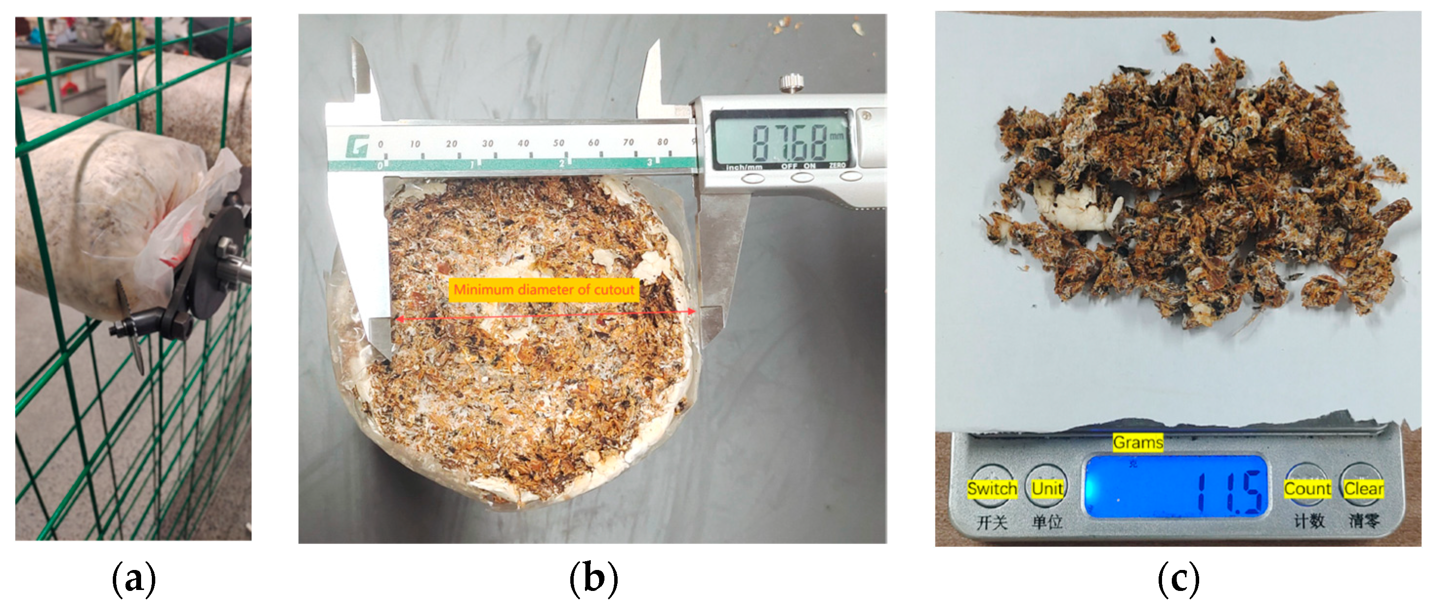
2.3. Cutout Performance Test

2.3.1. Test Equipment

The test was conducted on 8 April 2024, in the mushroom room of Chongqing Mushroom Easy Co., located in Hegeng Town, Yongchuan District, Chongqing, China (Coordinates: 105°37′37″~106°05′06″ E, 28°56′16″~29°34′23″ N), as shown in Figure 9a,b. The constructed P. pulmonarius stick cutting prototype recognized and positioned the P. pulmonarius stick on the cultivation frame via the vision system, and the control system guided the XYZ three-axis moving mechanism to drive the clamping and cutting device to precisely notch the P. pulmonarius stick.

2.3.2. Test Indicators and Methods

Since the cutter of the clamped and cutting mechanism cuts the bag of the P. pulmonarius stick by tensile tearing, this damage occurs when the deformation of the polypropylene plastic film exceeds its yield stress.
The performance test of this mushroom stick cutting machine is mainly aimed at testing the comprehensive cutting quality of P. pulmonarius mushroom sticks. However, during the notching process, issues such as severe tearing at the notch, the tearing of the mushroom stick bag, and excessive losses of the mushroom stick substrate arise, which reduce the quality of the mushroom and the economic benefits of subsequent mushroom production. Therefore, the roundness of the cut and the degree of loss of mushroom substrate were also selected as performance indices to evaluate the quality of the cut. Therefore, we chose the success rate of cutting, y 1 , the roundness of the cut, y 2 , and the degree of loss of cutout substrate, y 3 , as the target values for the design of the test, which are calculated using the following formulas:
y 1   =   ( 1 z 1 z ) × 100 % y 2   =   D d D y 3   =   ( 1 g G ) × 100 %
where z 1 is the number of unsuccessful cuts of the sticks, and z is the number of sticks that need to be cut before operation; D is the maximum diameter of the bag after cutting, d is the minimum diameter of the cut after cutting. The smaller the roundness y 2 of the cut, the better it is. G is the weight of the substrate, g is the remaining mass of the substrate after the cut of the P. pulmonarius stick, and y 3 is used to describe the roughness of the substrate on the cut surface of the stick; the larger the value, the more the stick substrate is lost and the rougher the cut surface.
Through the force analysis and literature review [18], it has been made evident that the cutting speed v is directly related to the cutting force of the tool, and the magnitude of the cutting force is related to the success rate of the cut y 1 , the roundness of the cut y 2 and the degree of loss of the cut substrate y 3 . The number of cut circles p is directly related to the length of the tensile tear of the plastic, and therefore is also an important factor in the performance test. Additionally, during the cutting process, the tool, the mushroom stick bag and the substrate interact with each other, and the cutting depth h of the tool has an important influence on their interaction, so the cutting depth of the tool is also an important factor affecting the performance of the cutter.
The range of values of the test parameters in this study was primarily selected based on the actual operation of the mushroom stick cutter and the results of the previous single-factor test selected. If the speed is too slow, the cutting force will be reduced, making it difficult to cut open the stick bag; if the speed is too fast, entanglement is more likely, increasing the risk of the test. If the number of cuts is too small, the stretch and tear distance will be insufficient and the success rate will be reduced; if the number of cuts is too large, energy will be wasted and efficiency will be reduced. If the cutting depth is too shallow, the contact between the cutter and the bag will not be sufficient and the efficiency of energy transfer will be reduced; if the cutting depth is too deep, excessive substrate will be lost from the mushroom, which will affect the quality of the subsequent mushroom production and the economic benefits.
Therefore, in this study, the values of the test parameters were set as follows: the cutting speed v was taken as 350 r/min, 400 r/min and 450 r/min, the number of cutting circles p was taken as 3, 5 and 7 circles, and the cutting depth h was taken as 3, 4 and 5 mm. On this basis, orthogonal tests were designed [19,20] to quickly find out the optimal working parameters of the mycorrhizal cutter, and to investigate whether there is a significant effect of the factors on cutting success, cutting roundness, the degree of loss of cutout substrate and the factors’ interaction. The orthogonal test method can be used to quickly determine the optimum working parameters of the mycorrhizal cutter and to investigate whether the factors have a significant effect on the cutting success rate, cutting roundness, cutting substrate loss, and their interaction. The experiment was designed using the L 9 ( 3 4 ) orthogonal table [21,22,23], and a three-factor, three-level quadratic orthogonal rotated combination test was used [24]. The coding table of the test factors is shown in Table 2, with a total of 17 test groups. To minimize random errors, each test group was repeated three times, and the average of the three results was taken as the final test result.

3. Results and Analysis

3.1. Test Results

The experimental program and results are shown in Table 3, where A, B, and C indicate the coded values for each factor.

3.2. Establishment of Regression Equation and Significance Analysis

The quadratic regression analysis of the test results was performed using Design Expert 8.0.6 software [25,26]. The regression mathematical model, with the success rate of cutting Y 1 , the roundness of the cut Y 2 , and the degree of loss of cutout substrate Y 3 as the response functions, and the coding table of each factor as the independent variable, is as follows:
Y 1   =   90.9   +   4.18 A   +   11.2 B   +   1.6 C   +   4.05 A B 1.2 A C 1.25 B C 4.73 A 2 7.83 B 2   +   1.17 C 2
Y 2   =   0.2 0.0164 A 0.0443 B 0.0454 C 0.0027 A B   +   0.03 A C 0.0257 B C   +   0.0425 A 2   +   0.1033 B 2   +   0.0175 C 2
Y 3   =   1.16   +   0.125 A   +   0.1625 B   +   0.3375 C 0.05 A B 0.05 A C 0.025 B C   +   0.0325 A 2   +   0.0575 B 2 0.0425 C 2
The test results and the variance analysis of the regression equation are shown in Table 4. The success rate, the roundness, and the degree of substrate loss at the cutout, along with their significance ( p     0.01 ) and the non-significant misfit terms of the regression models, indicate a good fit to the actual test data.
The regression equation of the success rate of P. pulmonarius stick cutting was analyzed. The analysis results show that the regression model of the success rate of the P. pulmonarius stick cutting had a p-value of < 0.05, indicating that the equation was well fitted and there was no loss of the fit factor. The regression coefficient of Equation (6) was tested, showing that the primary and secondary orders of factors affecting the success rate of cutting were the number of cutting circles, the cutting speed and the cutting depth.
The analysis results of the regression equation for the cut roundness of the P. pulmonarius stick show that the p-value for the cutting depth was greater than 0.05, indicating that the effect was not significant, while the other effects were significant. Regarding the roundness of the cut of the P. pulmonarius stick, the lack of fit term had a p-value of 0.0552 > 0.05, indicating that the equation is well fitted and there is no lack of fit factor. The regression coefficient of Equation (7) was tested, and the primary and secondary orders of factors affecting the success rate of cutting were the number of cutting circles, the cutting speed and the cutting depth.
According to the regression equation of the degree of loss of the cutout substrate, the analysis results show that the p-values of A, B, and C were less than 0.05, indicating significant effects, while the other effects were not significant. For the degree of loss of the cutout substrate, the lack of fit term had a p-value of = 0.1008 > 0.05, indicating that the equation fits well and there is no lack of fit factor. The regression coefficient of Equation (8) was tested, and the primary and secondary orders of factors affecting the success rate of cutting were cutting depth, the number of cutting circles and the cutting speed.

3.3. Factor Response Surface Analysis and Optimization

Response surface method analysis [27,28] was used to construct a regression model for the success rate of cutting, the roundness of the cut and the degree of loss of the cutout substrate by setting one of the test factors to zero while considering the effects of the other two factors on the test indices, and plotting the response surface graph.

3.3.1. Influence of Factors on the Success Rate of Cutting

As shown in Figure 10a, when the cutting depth is at the medium level and the cutting speed is fixed, with an increase in the number of cutting circles, the longer the cutter cuts the bag of P. pulmonarius sticks, the higher the success rate of cutting the stick. When the number of cutting circles is set, with an increase in the cutting speed, the cutting force of the cutter increases rapidly, and then tends to stabilize, such that the success rate of cutting also increases rapidly, and then tends to stabilize gradually. As shown in Figure 10b, when the number of cutting circles is at the medium level, the cutting speed is fixed at a fixed level, with increases in the depth of cut. The larger the contact area between the cutter and the bag of P. pulmonarius sticks, greater the success rate of cutting. When the depth of cut is certain and the cutting speed is increased, the cutting force of the cutter is rapidly increased, and then gradually tends to stability, as a result of which the success rate of the cut is also rapidly increased, and then gradually tends to stability. As shown in Figure 10c, when the cutting speed is medium, the number of cutting circles will stay at a fixed level; with the increase in the cutting depth, the larger the contact area between the blade and the bag of P. pulmonarius sticks, the greater the success rate of the cut. When the cutting depth is certain, with an increase in the number of cutting circles, the time the blade spends cutting the bag of P. pulmonarius sticks and the success rate of cutting the P. pulmonarius sticks both increase.

3.3.2. Influence of Factors on the Roundness of the Cut

As shown in Figure 11a, when the cutting depth is medium and the cutting speed is set at a fixed level, with increases in the number of cutting circles, the roundness of the cut of the P. pulmonarius stick decreases and then increases. When the number of cutting circles is fixed, with the gradual increase in the cutting speed, the cutting force gradually increases, making it easier for the blade to cut through the bag, ultimately leading to the roundness of the cut of the P. pulmonarius stick gradually decreasing. As the speed increases further, the stretching and tearing of the cutter on the side of the cut intensifies, resulting in further gradual increases in the roundness of the cut. As shown in Figure 11b, when the number of cutting circles is medium, the cutting speed will remain at a certain fixed level; with an increase in the depth of the cut, the contact between the blade and the bag of P. pulmonarius sticks will be more complete, and the roundness of the cut of the P. pulmonarius sticks will gradually become smaller; when the depth of the cut is certain, with the in cutting speed, the cutting force will gradually increase, and the blade will be more likely to cut through the bag of P. pulmonarius sticks, such that the roundness of the cut of the P. pulmonarius stick will gradually decrease first, and when the speed is increased further, the degree of tensile tearing of the blade on the side of the cutting edge will be intensified, such that the roundness of the cut will gradually increase further. As shown in Figure 11c, when the cutting speed is at a medium level, the number of cutting circles will remain at a fixed level; with increases in the depth of the cut and the fullness of the contact between the bag and the P. pulmonarius stick, the roundness of the cut of the P. pulmonarius stick will gradually become smaller. When the depth of the cut is certain, with increases in the number of cutting circles, the roundness of the cut of the P. pulmonarius stick will first be reduced and then will be increased. When the cutting speed was 419 r/min, the number of cutting circles was 6.2 r, and the depth of the cut was 5 mm; at this point, the roundness of the cut was the smallest.

3.3.3. Influence of Factors on the Degree of Loss of Cutout Substrate

As shown in Figure 12a–c, when one of the factors is at a medium level, and one of the other two factors is fixed, the degree of loss of cutout substrate becomes progressively greater as the last factor is progressively increased. This is because when the cutting speed is faster, the cutting force of the two cutter blades cutting the P. pulmonarius stick will be greater, and the impact of the cutter blades on the substrate of the P. pulmonarius stick will be stronger, resulting in a greater degree of loss of the substrate of the P. pulmonarius stick; the greater the number of rounds of incision, the longer the time required for the two cutter blades to cut the substrate of the rods, resulting in a greater degree of loss of the substrate of the P. pulmonarius stick; the deeper the depth of the cut, the greater the area of contact between the two blades and the substrate of the mushroom, and the greater the destructive ability of the blades at the time of cutting, resulting in a greater loss of substrate during cutting.
To obtain the best overall quality of the cut, the greatest cut success, the lowest cut roundness, and the lowest cutout substrate loss, the operating parameters of the P. pulmonarius stick blade were optimized and analyzed [29,30,31]. Design-Expert 8.0.6 software was used to obtain the optimal number of combinations of factors, as follows: the cutting speed of 376.3 r/min, the number of cutting circles of 5.4 r, and the depth of the cut of 4 mm. The success rate of the cut was 88.5%, the roundness of the cut was 0.241, and the degree of loss of cutout substrate was 0.88; the related data processing was carried out using the software Origin (version 2021).

4. Verification Test

To verify the reliability of the optimization results, the optimized parameters were bench-tested, as shown in Figure 13. The predicted values were an 88.5% success rate of cutting, a 0.241 roundness of the cut, and a 0.88% degree of loss of cutout substrate. The results of the bench test show that under the same parameter conditions, the success rate of cutting is 86.6%, the roundness of the cut is 0.235, and the degree of loss of cutout substrate is 0.851%, with an error of less than 5%, which is consistent with the optimization results. The results of the validation test show that the P. pulmonarius stick cutting machine designed by this research institute achieves a good cutting performance. Although the phenomenon of the blade tearing the outer packing bag of the P. pulmonarius stick occurs occasionally, it only has the initially expected effect. Subsequent improvements to the blade and improvements in the positioning accuracy of the vision system can further enhance the operational performance of the P. pulmonarius stick cutting machine.
In summary, this study designed a P. pulmonarius stick cutting device that can perform direct cutting operations on the net format P. pulmonarius stick cultivation frame. The P. pulmonarius stick cutting machine exhibits good cutting performance, causing minimal damage to both the outer packaging bag and the substrate of the P. pulmonarius stick, and it can meet the operation requirements of P. pulmonarius stick cutting.

5. Discussion

P. pulmonarius stick cutting faces sustainable development problems, such as labor shortages and rising labor costs in greenhouses, while the degree of mechanization in P. pulmonarius stick cutting, as one of the key processes in the production of bagged cultivated P. pulmonarius, directly restricts the development of the P. pulmonarius industry. At present, the research on mushroom stick cutting machinery mainly focuses on singular stationary machinery. In this study, based on the cultivation environment and material parameters of the P. pulmonarius stick, a self-propelled P. pulmonarius stick cutting machine was developed to perform cutting directly on the cultivation shelf, which uses the positive pressure torque provided by the grid steel wire of the cultivation shelf to overcome the rotational torque generated by the blade during cutting. This can basically replace the manual operation of cutting sticks as used in greenhouses, thus promoting the mechanization of the bag cultivation of P. pulmonarius sticks in China. This study provides a reference for the future research on mushroom stick cutting machinery.
The performance test results of the P. pulmonarius stick cutting machine are shown in Table 3. The cutting success rate of the cutting machine in the verification test reached 86.6%, which denotes the achievement of the cutting operation of P. pulmonarius sticks directly on the cultivation layer frame, and basically meets the demand for the mechanized cutting of P. pulmonarius sticks. The roundness of the cutting is 0.235, which means that there is no risk of tearing the bag of P. pulmonarius sticks every time the cutting is performed, and the roundness of the cutting achieved is very close to that achieved by manual cutting. In the current study, the cutting machine adopts an integrated working mode of “recognition–calculation–movement–notching”, which increases the intelligence level in the equipment used for cutting P. pulmonarius sticks. In order to further improve the integrated quality of cutting, it is necessary to consider not only the working parameters of the end-effector clamping cutter mechanism itself, but also a variety of factors such as the detection and positioning error of the vision system, the calibration error of the system, the error of the mechanism itself, the error of the feeding angle of the trolley, and the standardization of the P. pulmonarius sticks themselves. At present, there is a gap in the research on the quality of mushroom stick cuttings. The effective evaluation of the comprehensive quality of mushroom stick cutting provides a reference for the efficient cutting of mushroom sticks in the future.
Table 5 shows the advantages and limitations of the use of the end-effector clamping cutter mechanism compared to the bag breaking components of the other four cutters. From the table, it can be seen that the bag breaking components developed at this stage are large in size and only suitable for a single stationary cutter machine, making them unsuitable for operation in dense environments. The end-effector clamping cutter mechanism designed in this study has a smaller size, especially as regards the part that is in direct contact with the front of the canes, and it is therefore well-suited to mouth cutting operations between densely placed canes on the tiers of a cultivation frame. In addition, the use of a motorized cutting mechanism can significantly improve the efficiency of notching. However, the obvious disadvantage of the clamping and cutting mechanism is the high requirement for positioning accuracy, but relevant research is lacking in this area.
This machine can essentially realize the cutting operation of P. pulmonarius sticks directly on a cultivation layer rack, solving the dilemma of there being no machine available for use in P. pulmonarius stick cutting, and this stick cutting machine can also be used for cutting any edible mushroom sticks that might need end face cutting. This machine is suitable for the factory production of edible mushrooms, as the placement of the sticks is more standardized. When the machine is operated with the best working parameters, the cutter can complete the task of cutting 30~40 sticks per minute, while the efficiency of bag cutting for skilled workers is about 12 sticks per minute (the data are for reference only).

6. Conclusions

In order to solve the problem of directly realizing the cutting of P. pulmonarius sticks on a mesh-format stick cultivation layer rack, this paper has researched and designed a P. pulmonarius stick cutting machine, has adopted kinematics and dynamics analysis, regression analysis, response surface analysis, and experimental validation to derive comprehensive results.
(1) According to the cultivation environment and material characteristics of the P. pulmonarius sticks, a P. pulmonarius stick cutting machine was designed, which mainly consists of a clamping and cutting mechanism, an XYZ three-axis moving mechanism, a travelling trolley, a control system, and a visual system.
(2) The P. pulmonarius stick was selected as the test object in this study, and the universal testing machine was used to perform tensile and compression tests on the P. pulmonarius stick bag, resistance tests were performed on the blade cutting into the substrate of the P. pulmonarius stick, etc. The key components of the clamping and cutting mechanism were designed and selected, and kinematics and dynamics analyses were carried out on the clamping and cutting mechanisms and the P. pulmonarius stick itself in the process of operation. The cutting force, the maximum force F 1 and the maximum moment of the blade M 1 were calculated, and the minimum compression displacement of the grid steel wire into the P. pulmonarius stick was 2 mm. The results show that the blade can cut the outer packaging of the P. pulmonarius stick, and the P. pulmonarius stick does not rotate in the grid of the cultivation frame during incision operation.
(3) Using three-factor, three-level quadratic orthogonal rotary combination tests, a mathematical model was established between the cutting speed, the number of cutting circles, the depth of the cut and the success rate of cutting, while the roundness of the cut and the degree of loss of cutout substrate were assessed through orthogonal regression analysis. The effects of each factor on the success rate, roundness and cutout substrate loss were obtained through surface response analysis, and the optimal parameter combinations were determined as follows: the cutting speed was 376.3 r/min, the number of cutting circles was 5.4 r, and the depth of cutting was 4 mm. The success rate of cutting was 88.5%, the roundness of the cut was 0.241, and the degree of loss of cutout substrate was 0.88%. Finally, the validation of the bench test shows that the errors of each test were less than 5%, and it thus basically meets the needs set when cutting a P. pulmonarius stick.
The P. pulmonarius cutting machine designed in this paper is of guiding significance for the design of future mushroom stick cutting machinery. In future research, factors such as the material of the blade, the cutting method used, and the parameters of visual positioning accuracy will be considered in order to improve the working performance of the P. pulmonarius stick cutting machine.

Author Contributions

Conceptualization, C.C. and C.M.; methodology, Q.N.; software, C.C.; validation, C.C.; formal analysis, L.W.; investigation, P.J.; resources, Q.N.; data curation, L.W.; writing—original draft preparation, C.C.; writing—review and editing, C.L.; visualization, C.C.; supervision, H.J.; project administration, H.J.; funding acquisition, C.L. All authors have read and agreed to the published version of the manuscript.

Funding

This work was supported by the National Natural Science Foundation of China (51265046) and the Fundamental Research Funds for Central Universities (SWU019015).

Institutional Review Board Statement

Not applicable.

Informed Consent Statement

Not applicable.

Data Availability Statement

The original contributions presented in the study are included in the article; further inquiries can be directed to the corresponding author.

Acknowledgments

The authors sincerely acknowledge the members of the research team for their help.

Conflicts of Interest

The authors declare that they have no known competing financial interests or personal relationships that could have appeared to influence the work reported in this paper.

References

  1. Li, C.; Qu, M.; Cao, H.; Deng, W.; Shang, X.; Song, B.; Tan, Q. List of common names of edible fungi in China. J. Edible Fungi 2013, 20, 50–72. [Google Scholar] [CrossRef]
  2. Zhao, B.; Guo, Y. Progress in the extraction and purification of polysaccharides from edible mushrooms and their bioactivities. China Biotechnol. 2022, 42, 146–159. [Google Scholar] [CrossRef]
  3. Zhang, R.; Su, D.; Zhang, X. Nutrition and health function of mushroom and its product development. Food Res. Dev. 2004, 125–128. [Google Scholar]
  4. Yu, T.; Lian, X. Research progress on the mechanism of antitumor action of medicinal fungal polysaccharides. Contemp. Med. Symp. 2020, 18, 27–29. [Google Scholar]
  5. Liu, F.; Yuan, Z.; Yuan, B.; Ke, L.; Chen, G.; Xie, B. Biological characteristics and industrial cultivation technology of Xiuzhen mushroom. Edible Med. Mushrooms 2023, 31, 72–76. [Google Scholar]
  6. Liu, L.; Zhou, Y.; Chen, H.; Weng, B.; Lin, D.; Liu, P.; Jiang, Z. Research progress of Pleurous pulmonarius. Microbiol. China 2020, 47, 3650–3657. [Google Scholar] [CrossRef]
  7. Huang, Y. Analysis on the export situation of edible fungi in China in the post-epidemic era. Edible Med. Mushrooms 2021, 29, 369–371. [Google Scholar]
  8. Chian Edible Mushroom Association. Edible Fungi Society of China Analysis of the results of the national edible fungi statistical survey in 2022. Edible Fungi China 2024, 43, 118–126. [Google Scholar] [CrossRef]
  9. Li, Y.; Shang, X.; Song, C.; Li, Z.; Li, Q.; Tan, Q.; Zhou, F. Comparison of long stick model and breathable bag model in factory cultivation of mushroom. Edible Med. Mushrooms 2016, 24, 406–408. [Google Scholar]
  10. Cai, J.; Zhu, B. Key points of efficient fruiting management in the whole process of large-scale cultivation of Pleurous pulmonarius. Edible Med. Mushrooms 2022, 30, 154–157. [Google Scholar]
  11. Wang, X. Research and design of automatic cutting equipment for fungus packets. Farm Mach. Using Maint. 2021, 5, 11–13. [Google Scholar] [CrossRef]
  12. Ma, S. Study on Design and Key Technology of Mushroom Mushroom Bar Bag Bar Separator. Master’s Thesis, Chinese Academy of Agricultural Sciences, Beijing, China, 2023. [Google Scholar]
  13. Ma, S.; Song, W.; Wang, M.; Ding, T.; Wang, J.; Zhou, D. Research status and prospect of Chinese mushroom stick bagging equipment. J. Chin. Agric. Mech. 2022, 43, 50–55. [Google Scholar] [CrossRef]
  14. Liu, Y.; Hu, W.; Zhuang, H.; Pei, Z. Fibre bale automatic debanding and bag splitter bag cutting device design. Cotton Text. Technol. 2023, 51, 59–64. [Google Scholar]
  15. Wang, J. Application of light and simple facilities for high yield cultivation of Pleurous pulmonarius. Agric. Technol. 2018, 38, 74. [Google Scholar]
  16. GB/T 5262-2008; Measuring Methods for Agricultural Machinery Testing Conditions-General Rules. National Standardization Administration: Beijing, China, 2008.
  17. Xu, L.; Liu, X.; Zhang, K.; Xingfa, J.; Yuan, Q.; Chen, J.; Duan, Z.; Ma, S.; Yu, C. Design and testing of navel orange picking robot end-effector. Trans. Chin. Soc. Agric. Mach. 2018, 34, 53–61. [Google Scholar]
  18. Liu, Y. Damage Mechanism of Vegetable Pot Transplanting Pot and Optimization and Experiment of Planter Potting Movement. Ph.D. Thesis, Jiangsu University, Zhenjiang, China, 2020. [Google Scholar]
  19. Chen, J.; Zhao, J.; Chen, Y.; Bu, L.; Hu, G.; Zhang, E. Design and experimental optimization of vibrating medlar harvester. Trans. Chin. Soc. Agric. Mach. 2019, 50, 152–161+95. [Google Scholar]
  20. Yang, Z.; Stachler, R.; Heyne, J.S. Orthogonal Reference Surrogate Fuels for Operability Testing. Energies 2020, 13, 1948. [Google Scholar] [CrossRef]
  21. Tang, F.; Tong, S.; Zhang, H.; Li, W.; Chen, Z.; Zhen, Y. Analysis and test of reciprocating cutting and pruning parameters of apple branches. Trans. Chin. Soc. Agric. Eng. 2020, 36, 9–16. [Google Scholar]
  22. Liu, P.; He, J.; Li, Y.; Li, H.; Wang, Q.; Lu, C.; Zhang, Z.; Li, S. Design and test of opposite-speed roller type corn stover crushing and returning device. Trans. Chin. Soc. Agric. Eng. 2020, 36, 69–79. [Google Scholar]
  23. Cao, L.; Ma, C.; Jiao, H.; Ma, W.; Wang, L.; Li, C. Construction and testing of an empirical model for calculating the tumbled range of dry prickly ash particles on the separation belt. Comput. Electron. Agric. 2024, 218, 108711. [Google Scholar] [CrossRef]
  24. Zhang, X.; Guo, L.; Yan, J.; Shi, Z.; Kang, M.; Yao, J. Simulation Analysis and Parameter Optimization of Residual Film Pickup Process Based on Finite Element Method. Agriculture 2024, 14, 524. [Google Scholar] [CrossRef]
  25. Liu, Z.; Wang, T.; Liu, S.; Yan, X.; Zhao, H.; Wu, X.; Zhang, S. Design and Experimental Study of a Bionic Blade for Harvesting the Wild Chrysanthemum Stem. Agriculture 2023, 13, 190. [Google Scholar] [CrossRef]
  26. Zhang, L.; Yu, J.; Zhang, Q.; Liu, C.; Fang, X. Design and Experimental Study of Bionic Reverse Picking Header for Fresh Corn. Agriculture 2022, 13, 93. [Google Scholar] [CrossRef]
  27. Jia, C.; Wang, A.; Zong, L.; Yu, L. Structural optimization and performance improvement of rock drill seals based on orthogonal test. J. Eng. Appl. Sci. 2024, 71, 14. [Google Scholar] [CrossRef]
  28. Hannah, T.; Martin, V.; Ellis, S.; Kraft, R.H. High Speed Impact Testing of UHMWPE Composite Using Orthogonal Arrays. Exp. Mech. 2024, 64, 823–838. [Google Scholar] [CrossRef]
  29. Weng, W.; Chen, W.; Chen, L.; He, M.; Wang, J.; Zheng, S. Optimization of Working Parameters for Rotary-Cutting Soil Collection Device: Experiment and Simulation. Agriculture 2023, 14, 38. [Google Scholar] [CrossRef]
  30. Zhang, D.; Zuo, G.; Tong, J.; Zhang, Z. Optimization and experimentation of the working parameters of a bionic liquid-filled fertile soil device. Trans. Chin. Soc. Agric. Eng. 2020, 36, 31–39. [Google Scholar]
  31. Wang, Y.; Xia, X.; He, X.; Zhao, X.; Chen, J. Dynamics optimization and test of planting device with eccentric-elliptical gear planetary wheel system. Trans. Chin. Soc. Agric. Mach. 2017, 48, 38–46. [Google Scholar]
Figure 3. (a) Schematic diagram of P. pulmonarius stick cutting machine. (b) Side view of P. pulmonarius stick cutting machine.
Agriculture 14 01795 g003
Figure 4. Schematic diagram of the clamping and cutting mechanism.
Agriculture 14 01795 g004
Figure 5. Working process of clamping and cutting mechanism. (a) Initial state; (b) during clamping; (c) during incision.
Agriculture 14 01795 g005
Figure 6. Mathematical model and force analysis of P. pulmonarius stick. (a) Left view of the force on a fungus stick; (b) main view of the force on the sticks.
Agriculture 14 01795 g006
Figure 7. Indentation test and rolling bench test of the P. pulmonarius stick. (a) Positive pressure fitting curves under different compression displacements. (b) Detection of the average indentation depth.
Agriculture 14 01795 g007
Figure 8. Motion analysis and force analysis of clamping cutter mechanism.
Agriculture 14 01795 g008
Figure 9. Prototype and cutout test. (a) Samples; (b) cut-out test.
Agriculture 14 01795 g009
Figure 1. Cultivation environment and morphological parameters of Pleurous pulmonarius sticks. (a) Stereoscopic grid-type mushroom stick cultivation. (b) Parameters of mycorrhizal morphology measurements.
Agriculture 14 01795 g001
Figure 2. Resistance test for cutting the P. pulmonarius sticks. (a) Polypropylene tensile test. (b) Resistance test of cutter set into stick substrate for P. pulmonarius 5 mm.
Agriculture 14 01795 g002
Figure 10. Response surface curves of the factors affecting the success rate of cutting. (a) Y 1   =   f ( A , B , 0 ) ; (b) Y 1   =   f ( A , 0 , C ) ; (c) Y 1   =   f ( 0 , B , C ) .
Agriculture 14 01795 g010
Figure 11. Response surface curves of factors affecting cutting roundness. (a) Y 2   =   f ( A , B , 0 ) ; (b) Y 2   =   f ( A , 0 , C ) ; (c) Y 2   =   f ( 0 , B , C ) .
Agriculture 14 01795 g011
Figure 12. Response surface curves of the factors affecting the degree of loss of cutout substrate. (a) Y 3   =   f ( A , B , 0 ) ; (b) Y 3   =   f ( A , 0 , C ) ; (c) Y 3   =   f ( 0 , B , C ) .
Agriculture 14 01795 g012
Figure 13. Response surface curves of the factors affecting the degree of loss of cutout substrate. (a) Bench test; (b) notch roundness inspection; (c) detection of the degree of substrate loss in the cut.
Agriculture 14 01795 g013
Table 1. Geometrical parameters of P. pulmonarius stick.
ParametersValue
Diameter of P. pulmonarius stick d 1 /mm115
Ring diameter d 2 /mm50
Overall height h 1 /mm240
Height of bag opening from the bottom h 2 /mm190
Cylinder height h 3 /mm
Quality of Hidatsumi P. pulmonarius stick m /kg
180
1.25
Table 2. Experimental factor levels.
LevelsFactor
Cutting Speed vNumber of Cutout Turns pDepth of Cut h
−135033
040054
145075
Table 3. Orthogonal experiment arrangement and results.
No.FactorsResponse Values
Cutting Speed ANumber
of Cutout
Turns B
Depth
of Cut
C
Cutting
Success
Rate y 1 (%)
Roundness
of Cut y 2
Degree of Loss of Cutout Substrate y 3 (%)
1−1−1066.80.3401.0
21−1067.60.3301.3
3−11081.00.1981.3
411098.00.1201.4
5−10−180.80.2000.6
610−191.00.0801.0
7−10186.10.1001.4
810191.50.1501.6
90−1−170.00.3180.6
1001−195.00.0731.1
110−1176.00.2401.3
1201196.00.0161.7
1300091.00.1001.2
1400090.60.1001.1
1500090.90.0951.2
1600090.80.0971.1
1700091.20.0901.2
Table 4. Analysis of variance of test results and regression equation.
SourceSuccess Rate of IncisionRoundness of IncisionThe Degree of Loss of Cutout Substrate
Sum of SquaresFreedomF Valuep
Value
Sum of SquaresFreedomF Valuep ValueSum of SquaresFreedomF Valuep Value
Model1611.269179.03**0.13469267.75**1.30920.35**
A139.441139.44**0.031155.87**0.1250117.68**
B1003.5211003.52**0.057311025.80**0.2112129.87**
C20.48120.48**0.000110.9870 0.91131128.86**
AB65.61165.61**0.0012120.70**0.010011.41
AC5.7615.76**0.00721129.36**0.010011.41
BC6.2516.25**0.00681121.87**0.002510.3535
A294.00194.00**0.00771137.30**0.004410.6289
B2257.811257.81**0.04901878.13**0.013911.97
C25.8115.81**0.000213.26 0.007611.08
Lack of fit0.8030.270.06910.000336.200.05520.037534.170.1008
Pure Error0.2040.05 0.00014 0.01204
Sum1612.2616 0.135016 1.3416
Note: p < 0.01 (highly significant, **).
Table 5. Comparison of the clamping and cutting mechanism with four other bag breaking components.
Bag Breaking ComponentsCutting PartAdvantageLimitations
Ring cutter
[11]
Cylindrical sideUniformity of cut,
consistent depth
Large size, need to design specialized righting device
Cross-cutting, vertical cutting and flipping ring-cutting mechanism
[12]
Cylindrical ends and sidesFull cutout,
High efficiency and low loss
Higher tool sharpness requirements, faster tool wear, complex process
Longitudinal and circumferential cutting mechanisms
[13]
Cylindrical sideAutomatically adjusts the depth of cut by floating up and down according to the boosterLarge size, lower efficiency
Bottom serrated knife mechanism and side linear drive knife mechanism
[14]
Cylindrical ends and sidesFull range of cuts and high efficiencyComplicated and costly cutting process
Clamping and cutting mechanism (mine)Cylindrical front faceSmaller dimensions for flexible notching and high notching efficiencyHigher positioning accuracy requirements
Disclaimer/Publisher’s Note: The statements, opinions and data contained in all publications are solely those of the individual author(s) and contributor(s) and not of MDPI and/or the editor(s). MDPI and/or the editor(s) disclaim responsibility for any injury to people or property resulting from any ideas, methods, instructions or products referred to in the content.

