Article

Research on a Hydraulic Cylinder Pressure Control Method for Efficient Traction Operation in Electro-Hydraulic Hitch System of Electric Tractors

1
College of Engineering, China Agricultural University, Beijing 100083, China
2
BYD Company Limited, Shenzhen 518122, China
*
Author to whom correspondence should be addressed.
Agriculture 2023, 13(8), 1555; https://doi.org/10.3390/agriculture13081555
Submission received: 4 July 2023 / Revised: 1 August 2023 / Accepted: 1 August 2023 / Published: 3 August 2023
(This article belongs to the Special Issue Application of Modern Agricultural Equipment in Crop Cultivation)

Abstract

:
The tractor is the primary power device of the agricultural production process. For the problem that the traditional electro-hydraulic hitch control method for tractors cannot simultaneously meet the requirements of maintaining a constant ploughing depth and improving traction performance and electric tractor overall efficiency, this paper proposes a hydraulic cylinder pressure control method of the electro-hydraulic hitch system for electric tractors. We establish a tractor-implement system dynamic model, calculate the rear axle load of the tractor in real-time according to the actual working parameters under the premise of ensuring the constant ploughing depth, construct a traction performance objective optimization function, and use the genetic algorithm to solve the optimal hydraulic cylinder pressure value of the electro-hydraulic hitch system. Hardware-in-the-loop (HIL) simulation results show that the electric tractor under the traditional position control method and the hydraulic cylinder pressure control method has an average wheel slip of 18.50% and 16.93%, an average traction efficiency of 71.35% and 73.08%, and an average overall efficiency of 50.81% and 52.40%. The hydraulic cylinder pressure control method proposed in this paper reduces the wheel slip by 9.27%, increases the traction efficiency by 2.42%, improves the electric tractor overall efficiency by 3.13%, and reduces the electric tractor overall energy loss by 7.67% compared with the traditional position-control method. Therefore, the hydraulic cylinder pressure control method of the electro-hydraulic hitch system proposed in this paper can achieve the purpose of effectively improving tractor traction performance and reducing tractor energy loss while maintaining a constant ploughing depth. This study offers technological references for electric tractors to improve traction performance and reduce the overall energy loss of electric tractors.

1. Introduction

As the problems of global warming and the energy crisis continue to intensify, reducing fossil energy loss and achieving green development have become the main direction of future agriculture [1,2,3,4]. The tractor is the primary power device of the agricultural production process [5,6]. Currently, the vast majority of tractors rely on diesel engines as the power source to provide the driving force. However, these tractors suffer from issues such as low fuel efficiency, high fuel loss, and environmental pollution [5,7,8,9]. In contrast, electric tractors use an electric motor to provide the driving force, and these tractors have the benefits of low noise, high efficiency, and zero emissions [10,11]. Consequently, energy-saving and environmentally friendly electric tractors have become a focal point of research [12,13,14,15].
It was found that tractors lose about 20–55% of their energy during field operations due to the interaction between the soil and the tires [16]. Excessive wheel slip not only reduces traction efficiency but also causes tire wear. In response to this research finding, many studies have focused on reducing tire wear and the associated energy loss resulting from the interaction between tires and soil.
The wheel slip of a tractor can usually be controlled by directly adjusting the ploughing depth and driving wheel torque. Pranav et al. [17] designed a wheel slip automatic control system that adjusts the ploughing depth to control the wheel slip. The results showed that compared to traction force control systems, the slip control system improved traction efficiency by 4–10% and reduced fuel loss per hectare by 20–30%. Zhang et al. [18] proposed a combined traction-wheel slip control system based on PID control. Experimental results showed that the wheel slip fluctuation range of the tractor with rear-wheel drive could be reduced by 41.71%. Shafaei et al. [19] presented a method combining fuzzy depth and traction force control to regulate the wheel slip, resulting in a 34% decrease in wheel slip and a 20% increase in traction efficiency. All of the above methods aim to improve traction efficiency and reduce wheel slip by adjusting the ploughing depth and driving wheel torque, but they also make the ploughing depth fluctuate considerably and make it challenging to meet the agronomic requirements of traction operations.
The method of dynamically distributing the front and rear axle loads of the tractor to adjust the vertical load of the driving wheels also enables wheel slip control [20,21,22,23], which improves the traction performance of the driving wheels while maintaining a constant ploughing depth. Zhang et al. [24] proposed an intelligent ballast control system by taking advantage of the fact that the on-board battery pack accounts for 30–50% of the structural mass of the tractor and achieved dynamic distribution of the front and rear axle loads by using the longitudinal motion of the battery pack. Ning et al. [25] designed a mechanism for longitudinal movement of the battery position of electric tractors, set different battery positions for comparison tests, and found that adjusting the battery position could improve the tractive force by a maximum of 13.2%. However, these methods require an independent design of the battery movement mechanism and are challenging to apply widely.
In addition, by adjusting the hydraulic cylinder pressure of the electro-hydraulic hitch system, some or all of the weight of the plough is transferred to the rear axle of the tractor to increase the vertical load on the rear driving wheels, which in turn allows wheel slip control to improve driving wheel traction performance. Janis et al. [26] systematically analyzed the physical process of tractor implement operation and derived the relationship between hydraulic cylinder pressure variation and hitch system oscillation performance and tractor load variation. Meanwhile, Janis et al. [26] built a model of an electro-hydraulic hitch system in Working Model software and conducted a simulation verification test of hydraulic cylinder pressure control, and the simulation error of the system was 2%. Liu et al. [27] proposed a fuzzy PID algorithm based on a rule-based control method to achieve accurate tracking of hydraulic cylinder pressure during ploughing operation, providing a research basis for subsequent pressure control and floating control of electro-hydraulic hitch. Moitzi et al. [28] experimentally analyzed the effect of different plough widths, ploughing depths and hydraulic cylinder pressures on energy loss by applying different constant pressures to the hydraulic cylinders resulting in a maximum reduction of 10% in tractor fuel loss. However, all the above studies are rule-based graded hydraulic cylinder pressure control, without dynamically adjusting the hydraulic cylinder pressure for the tractor ploughing operation process in the ploughing resistance changes. And the dynamics of the electro-hydraulic hitch system dynamic operation process is complex, usually based on rules and a simplified model or rule-based pressure control method is difficult to further improve the control performance.
In summary, controlling the hydraulic cylinder pressure of the electro-hydraulic hitch system can change the dynamic load distribution between the front and rear axles of the tractor, thereby improving traction efficiency and reducing wheel slip. Aiming at the traditional traction force regulation system which is difficult to balance the agronomic requirements of improving traction performance and maintaining a constant ploughing depth as well as the low precision of the graded hydraulic cylinder pressure control method, this paper proposes a hydraulic cylinder pressure control method of electro-hydraulic hitch system for electric tractors. We establish the tractor-implement system dynamic model, calculate the tractor rear axle load in real time based on the actual working condition parameters under the condition of maintaining a constant ploughing depth, then construct the traction performance objective optimization function, and use the genetic algorithm to solve the magnitude of the optimal hydraulic cylinder pressure. The hydraulic cylinder pressure control method of the electro-hydraulic hitch system proposed in this paper can achieve the purpose of effectively improving traction performance and reducing the electric tractor overall energy loss while maintaining a constant ploughing depth.

2. Materials and Methods

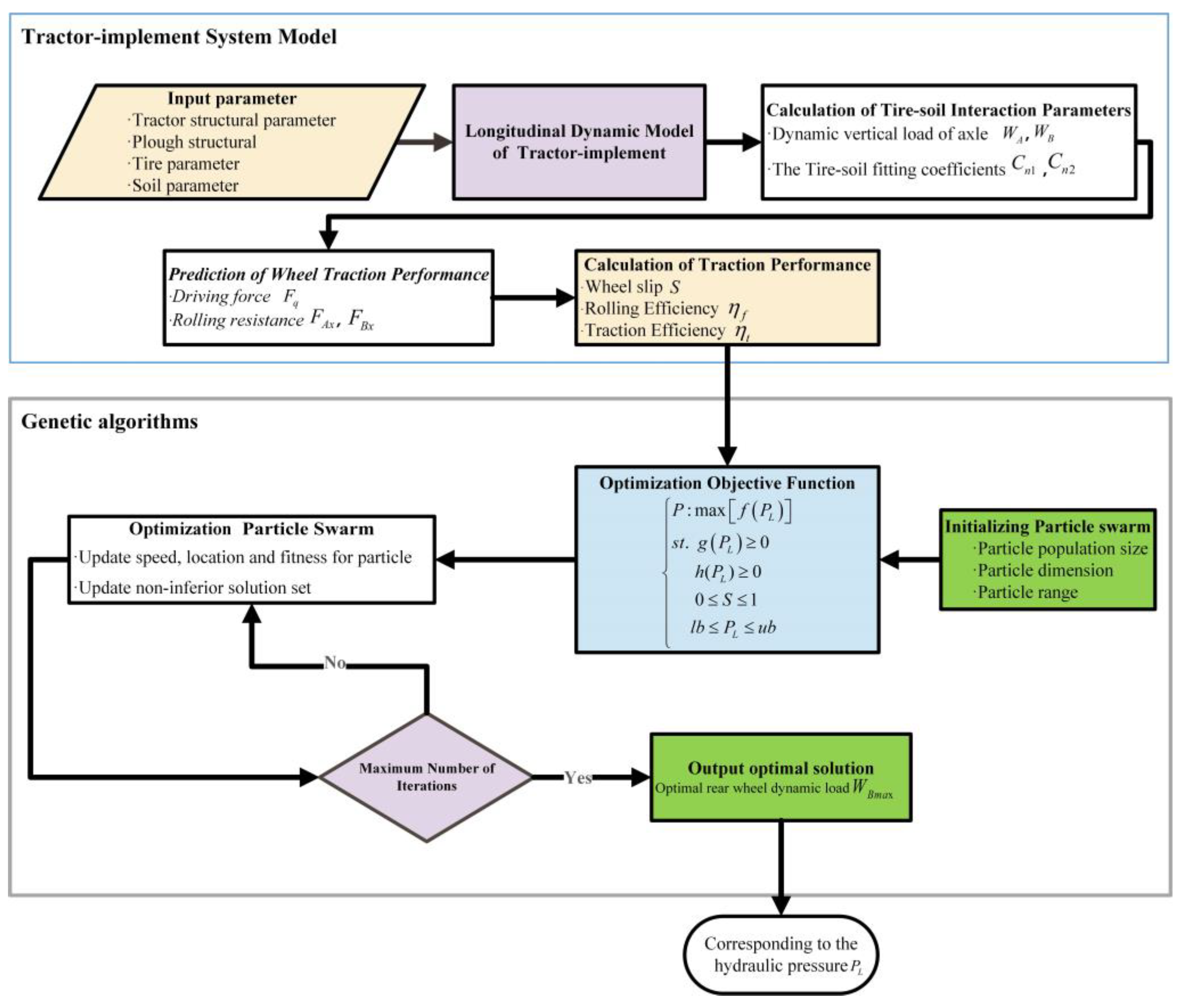
2.1. Traction Performance Prediction Model

Ploughing is one of the most common types of field operations performed by tractors. During ploughing, the tractor’s rear axle load increases due to the ploughing resistance on the implement and its weight, while the front axle load decreases. To accurately calculate the variation of front and rear axle loads during ploughing with an electric tractor, a dynamic model of an electric tractor implement system with rear-wheel drive is established as described below. By continuously monitoring the changes in traction provided by the three-point hitch of the electric tractor, it is possible to calculate drive force, rolling resistance, wheel slip and traction efficiency in real-time. This model is a foundation for the optimization of tractor traction performance in different soil conditions.

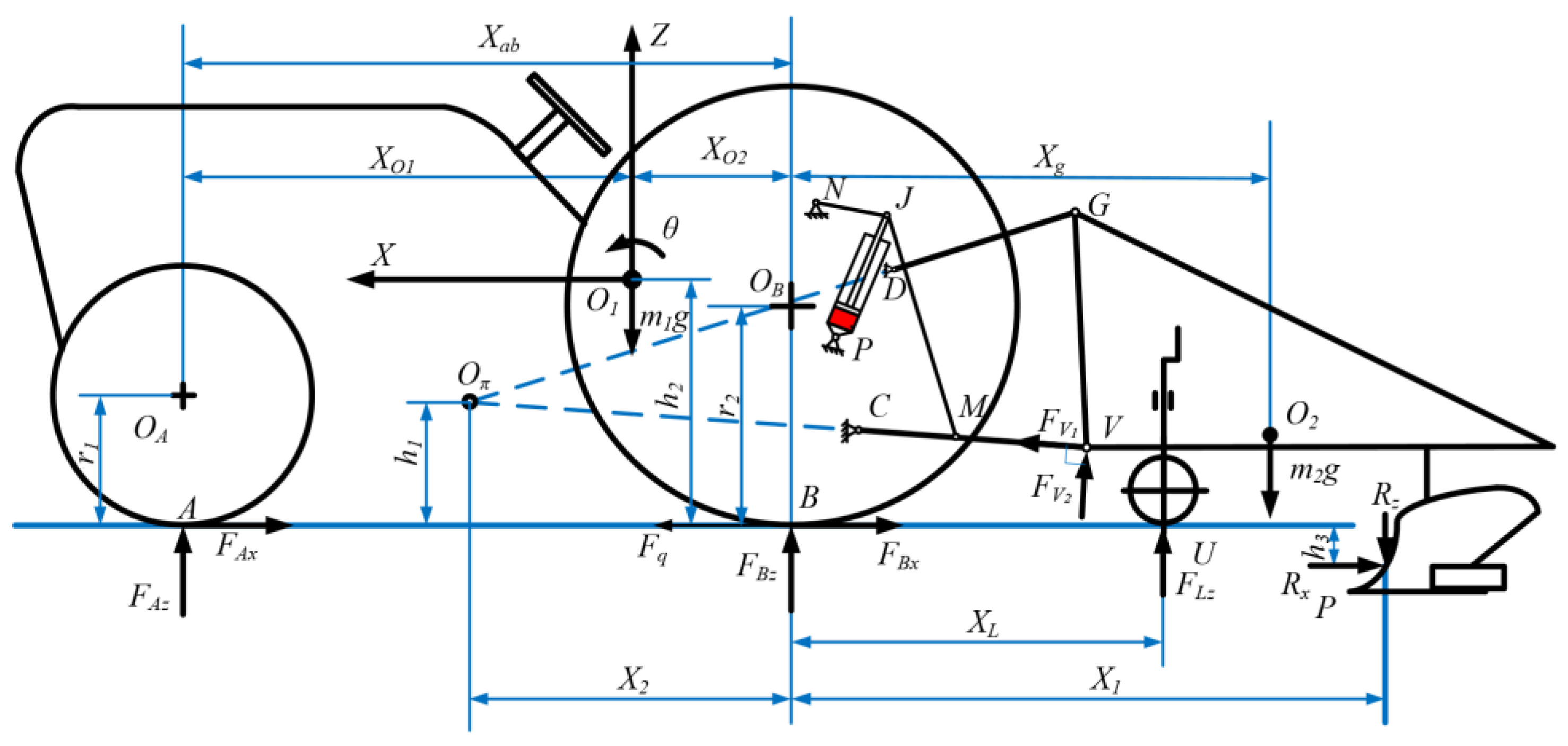
2.1.1. Tractor Implement System Dynamic Model

The center of mass of the tractor is taken as the origin, and the longitudinal plane of the electric tractor is used as the plane reference system to establish the dynamics model of the tractor in the longitudinal plane for longitudinal and vertical force analysis, as shown in Figure 1. Since the lateral motion of the electric tractor is not considered in this paper and the lateral motion in the forward process of the electric tractor is ignored, the motion of the electric tractor can be simplified to the motion in the longitudinal plane. Based on the balance of each force and moment of the tractor in the longitudinal plane, the equilibrium equations for the tractor’s forces and moments in the vertical and horizontal directions are established.

2.1.2. Force Analysis of Electric Tractor Implement System

(1)
Force Analysis of Electric Tractor under Static Load
When the tractor is operating in the field, the tires come under the contact of uneven terrain, causing the transfer of loads between the rear and front axles. Taking into account the pitch angle of the tractor, the static loads on the front and rear axles are calculated below:
W A 0 = F A z = m 1 g cos θ · X O 2 + m 1 g sin θ · h 2 X a b
W B 0 = F B z = m 1 g cos θ · X O 1 m 1 g sin θ · h 2 X a b
where WA0 is the static vertical load on the front axles of the electric tractor, and WB0 is the static vertical load on the rear axle, m1 is the total mass of the electric tractor, XO1 is the horizontal distance from the front axle to the center of mass of the tractor, XO2 is the horizontal distance from the rear axle to the center of mass of the tractor, Xab is the horizontal wheelbase between the front and rear axles, θ is the tractor’s pitch angle, and h2 is the vertical distance from the tractor’s center of mass to the ground.
(2)
Force Analysis of Electric Tractor under Dynamic Load
The electric tractor with the mounted plough is operating in the field at a constant speed with an acceleration of zero, considering the effect of the role of the three-point hitch, the weight of the plough, the force between the depth-limiting wheel and the soil, and the ploughing depth on the amount of vertical load variation on the rear and front axles of the electric tractor. The formulas for calculating the vertical load variations of the front and rear axles are as follows:
Δ W A = R z · X 1 R x · h 3 F L z · X L + m 2 g · X g X a b
Δ W B = R z · ( X 1 + X a b ) R x · h 3 F L z · ( X L + X a b ) + m 2 g · ( X g + X a b ) X a b
where ∆WA is the amount of variation of vertical load on the front axles, and ∆WB is the amount of variation of vertical load on the rear axles. RZ and Rx are the vertical and horizontal ploughing resistance of the soil acting on the plough, respectively. m2 is the total mass of the plough. X1 is the horizontal distance from the point where the plough is subjected to force to the rear axle. XL is the horizontal distance from the depth-limiting wheel to the rear axle. Xg is the horizontal distance from the center of mass of the plough to the center of mass of the tractor. h3 is the vertical distance from the point where the plough is subjected to ploughing resistance to the horizontal ground.
(3)
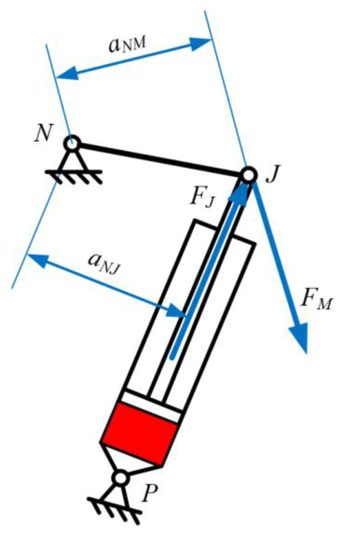
Force Analysis on Lift Arm
As shown in Figure 2, the force on the NJ lift arm includes the lift link tension FM and hydraulic cylinder thrust force FJ.
F M a N M F J a N J = 0
F J = π d 2 4 P L
where FM is the lift link tension, FJ is the hydraulic cylinder thrust, aNJ is the distance from the rotation axis N of the lift arm of the hitch to the axis of the hydraulic cylinder PJ in the longitudinal plane, aNM is the distance from the rotation axis N of the lift arm of the hitch device to the lift link axis JM in the longitudinal plane, d is the diameter of the hydraulic cylinder, and PL is the hydraulic cylinder pressure provided by the hydraulic cylinder.
(4)
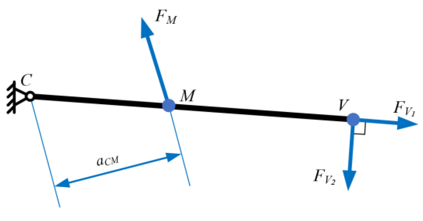
Individual Force Analysis of the Lower Link CV
As shown in Figure 3, the forces on the lower tie bar CV include the force FV1 along the CV direction, the force FV2 in the vertical CV direction at the lower hitch point V, and the force FM at the articulation point M of the lift link. The moment for point C is taken as follows:
F M a C M F V 2 a C V = 0
where FV2 is the vertical force of CV, aCM is the distance from the lower connection point C of the lower link to the lift link axis JM in the longitudinal plane, and aCV is the distance in the longitudinal plane between the lower connection point C on the lower link and the lower hitch point V.
(5)
Force Analysis of Hitch Implement
As shown in Figure 1, the force of the hitch implement includes the vertical and horizontal ploughing resistance RZ and Rx of the soil acting on the plough, the vertical upward supporting force FLZ exerted by the soil on the depth-limiting wheel of the plough, the total mass m2 of the plough, and the force FV1 along the CV direction and the force FV2 in the vertical CV direction at the lower hitch point V. The moment for the longitudinal transient center Oπ is shown below:
R z ( X 1 + X 2 ) R x ( h 1 + h 3 ) + m 2 g ( X g + X 2 ) ( X L + X 2 ) F L z F V 2 a O π V = 0
where aSV is the distance from the longitudinal transient center Oπ to the lower hitch point V in the longitudinal plane.
Combining the above Equations (5)–(8), it can be concluded that
F L z = R z ( X 1 + X 2 ) R x ( h 1 + h 3 ) + m 2 g ( X g + X 2 ) X L + X 2 a N J · a C M · a O π V · π d 2 4 a N M · a C V ( X L + X 2 ) P L
In accordance with the above formulas, the wheel’s vertical load is affected by the hydraulic cylinder pressure, the position of the center of mass of the tractor, the ploughing resistance, and the ploughing depth. The front and rear axle loads at this point are calculated below:
W A = W A 0 Δ W A = ( m 1 g cos θ · X O 2 + m 1 g sin θ · h 2 R z · X 1 + R x · h 3 + F L z · X L m 2 g · X g ) / X a b
W B = W B 0 + Δ W B = [ m 1 g cos θ · X O 1 m 1 g sin θ · h 2 + R z · ( X 1 + X a b ) R x · h 3 F L z · ( X L + X a b ) + m 2 g · ( X g + X a b ) ] / X a b

2.1.3. Tire–Soil Interaction Model

Due to the variable soil conditions, the interaction relationship between soil and tire is complex, so to accurately describe the interaction between soil and tire, this paper adopts the geneticized model proposed by Wismer et al. [29] to predict the longitudinal force of soil on tires. Tire–soil interaction schematic is shown in Figure 4. For rear-wheel drive electric tractors, the relationship between tire rolling resistance, the driving force, wheel slip, soil parameters, load on the front and rear axles, and tire structural parameters provided by this model can be expressed as follows:
φ q = F q W B = 0.75 ( 1 e 0.3 C n 2 S )
f 1 = F A x W A = 1.2 C n 1 + 0.04
f 2 = F B x W B = 1.2 C n 2 + 0.04
where φq is the driving force coefficient. f1, f2 are the rolling resistance coefficients for the front wheels, and f2 is the rolling resistance coefficients for the rear wheels. Fq is the total driving force on the tractor’s driving wheels. S is the wheel slip of the driving wheels. FAx and FBx are the rolling resistances of the front and rear wheels, respectively. Cn1 and Cn2 are the tire–soil fitting coefficients for the front and rear wheels, respectively, calculated by the following equations:
C n 1 = C I b 1 d 1 W A
C n 2 = C I b 2 d 2 W B
where b1 and d1 are the section width and diameter of the front tire, b2 and d2 are the section width and diameter of the rear tire, respectively, and CI is the cone index.
Soil conditions can affect the traction performance of tires. The more solid the soil is, the larger the CI and Cn values are, and the tire produces more driving force at the same slip. Therefore, the traction performance of the tire increases. However, considering that the solid soil leads to an increase in the ploughing resistance, the energy loss of the tractor is increased as well.

2.1.4. Traction Performance Model

The electric tractor’s traction efficiency is the ratio of the traction power to the effective output power of the drive motor when the electric tractor travels at a constant speed on the horizontal ground for traction operation. It can be expressed as:
η t = P t P m = F t v T m ω m = F q v T T m ω m F t v F q v v v T = η m · η f · η s
where Pt is the traction power, Pm is the output power of the motor drive system, Ft is the traction force, ωm is the motor output speed, Tm is the motor output torque, v is the actual travel speed of the tractor, vT is the theoretical travel speed of the tractor, ŋm is the mechanical transmission efficiency, ŋf is the rolling efficiency, and ŋs is the slip efficiency.
The traction efficiency is mainly composed of mechanical transmission efficiency, rolling efficiency, and slip efficiency. Mechanical transmission efficiency is the efficiency of the transmission system and is usually assumed to be a constant value. For wheeled tractors, it can be generally taken as about 0.9.
The rolling efficiency is the ratio of the power of pulling the implement to the power of driving the tractor. It can be expressed in the following equation:
η f = F t v F q v = 1 F A x + F B x F q
The slip efficiency is defined as the ratio of the actual speed of the tractor to the theoretical speed, and the following equation can calculate it:
η s = v v T = 1 S
Electric tractor overall efficiency ŋoverall is defined as the ratio of the traction power to the input power of the electric motor drive system, and it can be calculated as follows:
η o v e r a l l = P t P i = F t v U I = T m ω m U I F t v T T m ω m = η t · η e
where Pi is the motor’s input power, U is the motor drive system’s input voltage, I is the motor drive system’s input current, and ŋe is the efficiency of the motor drive system, including the motor controller and motor efficiency. It is affected by the motor characteristics, and it varies with the motor’s output torque and speed and with the temperature of the ambient environment.

2.2. Hydraulic Cylinder Pressure Optimization Method

The hydraulic cylinder pressure is controlled by the hydraulic cylinder pressure control method of the electro-hydraulic hitch system to achieve changes in axle load. Therefore, determining the optimal hydraulic cylinder pressure is crucial for achieving the effective hydraulic cylinder pressure control method of the electro-hydraulic hitch system. Based on the traction characteristics of the tractor implement system, the dynamic loads on the front and rear axles of the tractor are calculated in real-time in conjunction with the changes in actual ploughing resistance. Then, the optimal load for the rear axle is determined and the corresponding hydraulic cylinder pressure is obtained.
The traction performance mainly depends on the structural parameters of the tractor, soil parameters, the driving speed of the tractor, and the traction force of the drawbar. This study primarily focuses on improving the traction performance of tractors through the following aspects:
(1)
Traction Efficiency: Improving the energy efficiency of tractor traction operations in the field and ensuring the driving range of electric tractors with fixed battery capacity. Optimizing the traction efficiency of electric tractors is crucial for traction operations in the field.
(2)
The Wheel Slip: Under field operating conditions, excessive wheel slip of tractor driving wheels can cause serious damage to soil quality, increase tire wear, and result in additional energy loss. Therefore, it is also necessary to reduce the wheel slip of the rear wheels while improving traction efficiency, which can reduce the additional energy loss.
(3)
Front and Rear Axle Dynamic Loads and Distribution Ratio: Under field operating conditions, increasing the rear wheel load and reducing the front wheel load are beneficial for improving traction efficiency. However, it is not always better to have a larger rear wheel load. Numerous experimental results have shown that to ensure the safe and stable maneuverability of the tractor, the dynamic load coefficient of the front axle should not be less than 0.2 [29].
In conclusion, the optimizing traction performance of an electric tractor can be formulated as a single objective function optimization question. The optimization mathematical model is derived below:
{ P : max [ f ( P L ) ] s t . g ( P L ) 0 h ( P L ) 0   0 S 1 l b P L u b
where condition P is the maximum value of the objective optimization function, and st. is the constraints of the optimization function. f(PL) is the traction efficiency, g(PL) is the dynamic load coefficient of the front axle, and h(PL) is the soil support force on the depth-limiting wheel. lb and ub are the minimum and maximum values of the variables, and g(PL) and h(PL) are equations with inequality constraints.
{ f ( P L ) = 0.9 × ( 1 F A x + F B x F q ) ( 1 S ) = 0.9 × F T 0.75 F L z ( 1 e 0.3 C I b 2 d 2 S / F L z ) × ( 1 S ) S = 1 0.3 C n 2 ln 0.75 W B R x F L x ( 1.2 C n 1 1 + 0.04 ) W A ( 1.2 C n 2 1 + 0.04 ) W B 0.75 W B g ( P L ) = W A W A + W B 0.2 = ( m 1 g cos θ · X O 2 + m 1 g sin θ · h 2 R z · X 1 + R x · h 3 + F L z · X L m 2 g · X g ) / X a b m 1 g cos θ + m 2 g + R z F L z 0.2 h ( P L ) = F L z = R z ( X 1 + X 2 ) R x ( h 1 + h 3 ) + m 2 g ( X g + X 2 ) X L + X 2 a N C · a C M · a O π V · π d 2 4 a N D · a C V ( X L + X 2 ) P L l b = 0 u b = 4 a N D · a C V ( X L + X 2 ) a N C · a C M · a O π V · π d 2 m 2 g
Genetic algorithms are a class of randomized search methods that evolved from the laws of evolution in biology (survival of the fittest, survival of the fittest genetic mechanism). It has efficient global search ability, good nonlinear processing ability, and good generality and robustness. Therefore, based on the traction performance prediction model, this study introduces a genetic algorithm to dynamically find the optimal hydraulic cylinder pressure. First, the traction performance prediction model was used to predict traction efficiency and wheel slip during tractor operation. Subsequently, online optimization was performed using genetic algorithms to obtain the best traction efficiency and rear axle dynamic load. Based on this, the optimal hydraulic cylinder pressure was calculated. Eventually, closed-loop control of the hydraulic cylinder pressure is achieved using a hydraulic cylinder. The specific flow chart is shown in Figure 5 below.

2.3. System Validation

System validation is necessary to validate the feasibility and accuracy of the hydraulic cylinder pressure control method of the electro-hydraulic hitch system. This consists of MATLAB/Simulink simulations and hardware-in-the-loop (HIL) testing.

2.3.1. MATLAB/Simulink Simulation

The impact of driving wheel load on traction performance is investigated, and the feasibility of improving traction performance through the hydraulic cylinder pressure control method of the electro-hydraulic hitch system is validated. An electric tractor traction performance simulation model is developed by using MATLAB/Simulink 2018b and is simulated under specific operational conditions. Based on the traction performance prediction model, the traction performance is mainly influenced by the traction force and the driving wheel load while keeping the tire and soil parameters constant.

2.3.2. Hardware-in-the-Loop (HIL) Simulation Testing

To test the feasibility and real-time performance of the hydraulic cylinder pressure control method of the electro-hydraulic hitch system, HIL testing is conducted using the dSPACE simulation platform. First, an HIL testbed consisting of the dSPACE 1007 simulation platform, the tractor controller, and the host computer was constructed, as shown in Figure 6. Then, MATLAB/Simulink 2018b software was used to establish the dynamic model of the tractor execution system. The dynamic model of the tractor implement system is used in dSPACE 1007 in real-time during testing. In addition, the three-dimensional posture of the tractor and the tillage resistance data were provided to the model as excitation signals. Speed, slip, motor speed, and torque are sent as tractor state variables to the tractor controller via the CAN bus. The hydraulic cylinder pressure control method ran in real-time on the tractor controller to calculate the motor drive torque. The driving torque command and hydraulic cylinder pressure control signal were transmitted to the dSPACE platform via the CAN bus to achieve efficient ploughing. The master PC can capture and display all the test information. The HIL test is based on a 20 hp rear wheel independent drive electric tractor where the motor drives the tires directly through a planetary gearbox. The tractor and soil parameters used in the HIL testing are shown in Table 1.
The tractor conducted field ploughing tests at Shangzhuang Experimental Station in Changping District, Beijing. The plough used in the ploughing tests had two ploughshares that provided a ploughing depth of 150 mm and a total ploughing width of 500 mm. The ploughing resistance measurement data (shown in Figure 7) during ploughing was utilized in the HIL test. In the field test, the tractor traveled at an average speed of roughly 4 km/h, so in the HIL test, the target travel speed of the electric tractor was set at 4 km/h. The soil conditions remained constant throughout the ploughing experiments. In addition, the electric tractor start-up and acceleration processes are not considered here in order to ensure the accuracy and stability of the test data when performing the HIL tests and data analysis.
To verify the effectiveness of the hydraulic cylinder pressure control method of the electro-hydraulic hitch system in improving traction performance and energy efficiency, two operating modes are designed in this study.
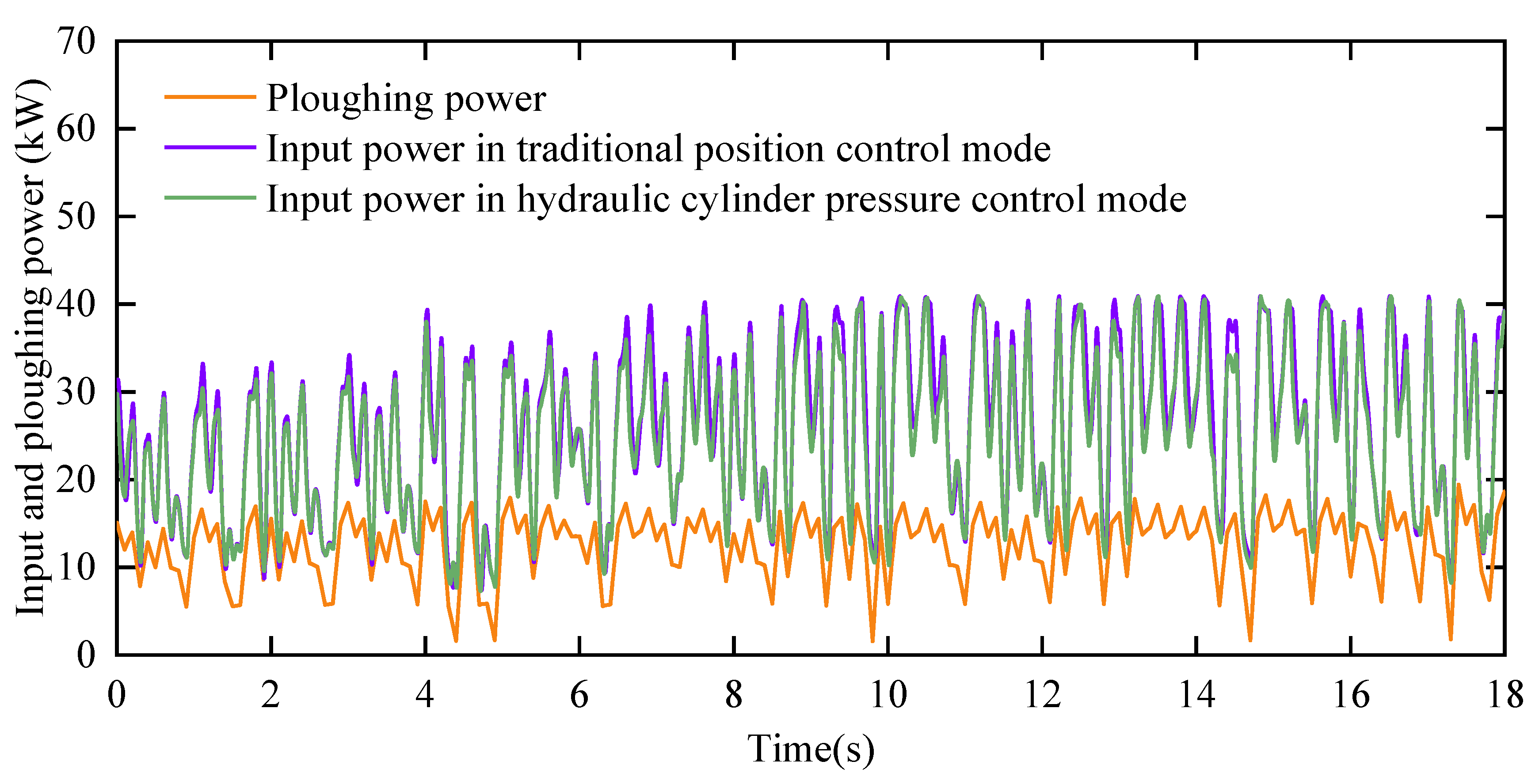
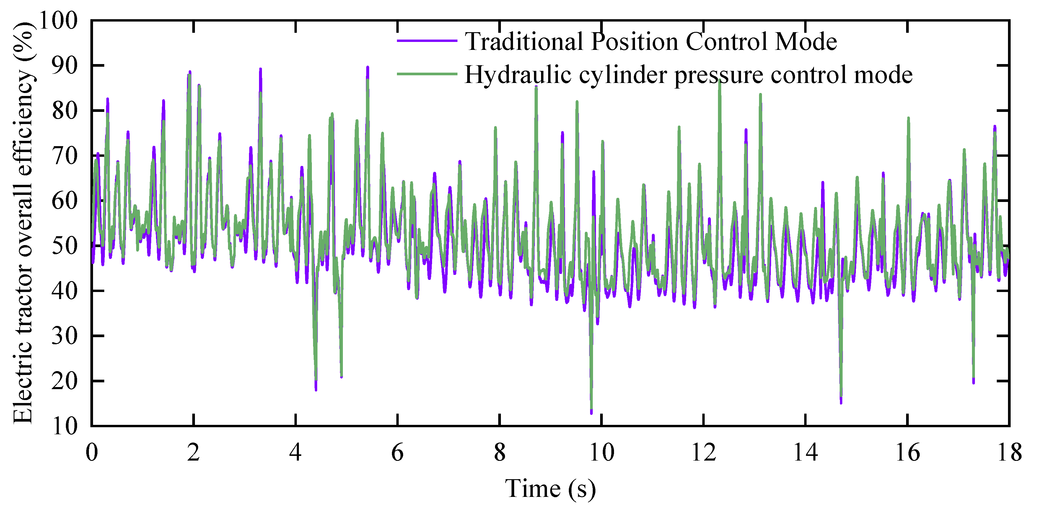
  • Traditional position control mode: In this mode, the ploughing depth is controlled at a constant value, the hydraulic cylinder position is locked, and the pressure in the hydraulic cylinder fluctuates with the load within the rated range.
  • Hydraulic cylinder pressure control mode: In this mode, the proposed hydraulic cylinder pressure control method is applied to the electro-hydraulic hitch system and constrains the pressure control range to maintain a constant ploughing depth. The control cycle is set to 100 ms.

3. Results and Discussion

Figure 8 illustrates the variation of ploughing resistance and optimal hydraulic cylinder pressure values under the hydraulic cylinder pressure control mode.
When the ploughing resistance fluctuates around 3000 N, the optimal hydraulic cylinder pressure value fluctuates around 1.0 MPa. When the ploughing resistance is below 1000 N, the optimal hydraulic cylinder pressure value fluctuates around 0.3 MPa. The average value of the optimal hydraulic cylinder pressure output under the hydraulic cylinder pressure control mode is 0.35 MPa. From Figure 8 can be observed that the hydraulic cylinder pressure value with the ploughing resistance varies and fluctuates when the ploughing resistance increases. If the wheel slip is high, then the hydraulic cylinder pressure value is also increased in order to improve the driving capacity of the drive wheels. If the wheel slip is low due to the ploughing, resistance increases have made the rear axle load increase, and the hydraulic cylinder pressure value is not significantly increased in order to ensure that the front wheels’ steering capacity. Further, soil conditions can indirectly affect the pressure value of the hydraulic cylinders, with solid soil resulting in both improved traction performance and increased plow resistance and soft soil resulting in reduced traction performance and reduced plow resistance. The value of ploughing resistance directly affects the front and rear axle load ratios, and the optimization process of the hydraulic cylinder pressure value is the balancing process of traction performance and front and rear axle load ratios.
In summary, the optimal hydraulic cylinder pressure value dynamically changes in real-time with the fluctuation of ploughing resistance. It improves traction efficiency and reduces wheel slip while ensuring smooth tractor operation. This demonstrates the feasibility of the online algorithm for solving the optimal hydraulic cylinder pressure.
The wheel slip refers to the ratio of the difference between the theoretical speed and the actual speed of the tractor to the theoretical speed. A higher wheel slip indicates more severe tire wear, leading to increased energy loss and decreased traction performance of the tractor.
Figure 9 illustrates the curve of the wheel slip for the electric tractor under the traditional position control mode and the hydraulic cylinder pressure control mode. Under the traditional position control mode, the average wheel slip is 18.50%. Under the hydraulic cylinder pressure control mode, the average wheel slip is 16.93%. Compared to the traditional position control mode, the wheel slip of the tractor decreases by 9.27% with the implementation of the hydraulic cylinder pressure control method. This indicates that the hydraulic cylinder pressure control method can effectively reduce tire slip, thereby reducing tire wear, reducing energy loss, and improving the traction performance of the electric tractor.
Figure 10 illustrates the wheel speed and wheel torque of the electric tractor under the hydraulic cylinder pressure control mode. Combined with the ploughing resistance curve shown in Figure 7, it can be seen that when the ploughing resistance suddenly increases, the wheel torque increases as well in order to maintain the speed of the vehicle, and the wheel speed is subsequently increases significantly in order to increase the wheel slip, which leads to an increase in the wheel driving force and traction force. The variation in wheel speed and torque matches the actual process of ploughing operations.
Figure 11 illustrates the tractor travel speed curve under the hydraulic cylinder pressure control mode, where it can be observed that the tractor speed varies with ploughing resistance in Figure 7. It is significant that when the ploughing resistance increases, the tractor speed subsequently decreases, and when the ploughing resistance decreases, the tractor speed subsequently increases, which is due to the fact that the tractor operating conditions we have chosen are harsh. The large fluctuations of the ploughing resistance causes the tractor speed to fluctuate around our target speed of 0.8 m/s, and this fluctuation matches the actual process of ploughing operations.
Energy loss refers to the difference between the input energy and the energy used for ploughing. Figure 12 illustrates the comparison of energy loss variation curves between the traditional position control mode and the hydraulic cylinder pressure control mode.
From the analysis of Figure 12, it can be observed that the energy loss in the hydraulic cylinder pressure control mode remains lower than that in the traditional position control mode. In the traditional position control mode, the average energy loss of the electric tractor is 42.55 Wh, while in the hydraulic cylinder pressure control mode, the energy loss is reduced to 39.52 Wh. This represents a reduction of 7.67% in energy loss compared to the traditional position control mode. These results demonstrate that the hydraulic cylinder pressure control method effectively reduces the energy loss of the electric tractor during traction operations, thereby increasing the energy utilization rate.
Figure 13 illustrates the trend of the input power and ploughing power curves in both modes. Table 2 presents the power parameters for each mode. From Figure 13, it can be observed that the ploughing power is the same in both modes. The average input power for the traditional position control mode is 25.77 kW, while the average input power for the hydraulic cylinder pressure control mode is 24.81 kW. Compared to the traditional position control mode, there is a reduction of 3.87% in input power. Furthermore, the hydraulic cylinder pressure control mode exhibits lower fluctuations in input power. Therefore, the hydraulic cylinder pressure control method effectively reduces motor power loss and enhances traction performance.
Traction efficiency is a parameter that includes mechanical efficiency, rolling efficiency, and wheel slip. It represents the ratio between the traction power of the tractor and the corresponding effective power of the engine.
Figure 14 illustrates the variation curves of traction efficiency for both the traditional position control mode and the hydraulic cylinder pressure control mode of the electric tractor. The traditional position control mode refers to the tractor operating without hydraulic cylinder pressure control. Analyzing Figure 12 reveals that the average traction efficiency in the traditional position control mode is 71.35%. In contrast, the average traction efficiency in the hydraulic cylinder pressure control mode is 73.08%, indicating an improvement of 2.42% compared to the traditional position control mode. Therefore, the hydraulic cylinder pressure control method effectively enhances the traction efficiency of the electric tractor during field traction operations, thereby improving its overall traction performance.
Figure 15 presents the variation trend of electric tractor overall efficiency in both the traditional position control mode and the hydraulic cylinder pressure control mode. Electric tractor overall efficiency is the ratio of traction power to motor drive system input power.
In the traditional position control mode, the average value of the electric tractor overall efficiency is 50.81%. However, in the hydraulic cylinder pressure control mode, the average value of the electric tractor overall efficiency reaches 52.40%, indicating an improvement of 3.13% compared to the traditional position control mode.

4. Conclusions

This study proposed a hydraulic cylinder pressure control method of the electro-hydraulic hitch system that improved the traction performance of electric tractors and reduced the electric tractor overall energy loss while maintaining a constant ploughing depth. The primary purpose of this work was to solve the problem that the traditional traction control system could not do both to ensure a constant ploughing depth and improve traction performance. A tractor implement system dynamic model was established, and a genetic algorithm was used to calculate the dynamic load on the front and rear axles in combination with the ploughing resistance to determine the optimal hydraulic cylinder pressure value of the hydraulic cylinder in real-time. Subsequently, the hydraulic cylinder pressure control method of the electro-hydraulic hitch system was controlled by the tractor controller to achieve real-time control of the optimal hydraulic cylinder pressure. Finally, a simulation model of the electric tractor’s traction performance was developed and simulated under specified operating conditions. The conclusions of this study were as follows:
(1)
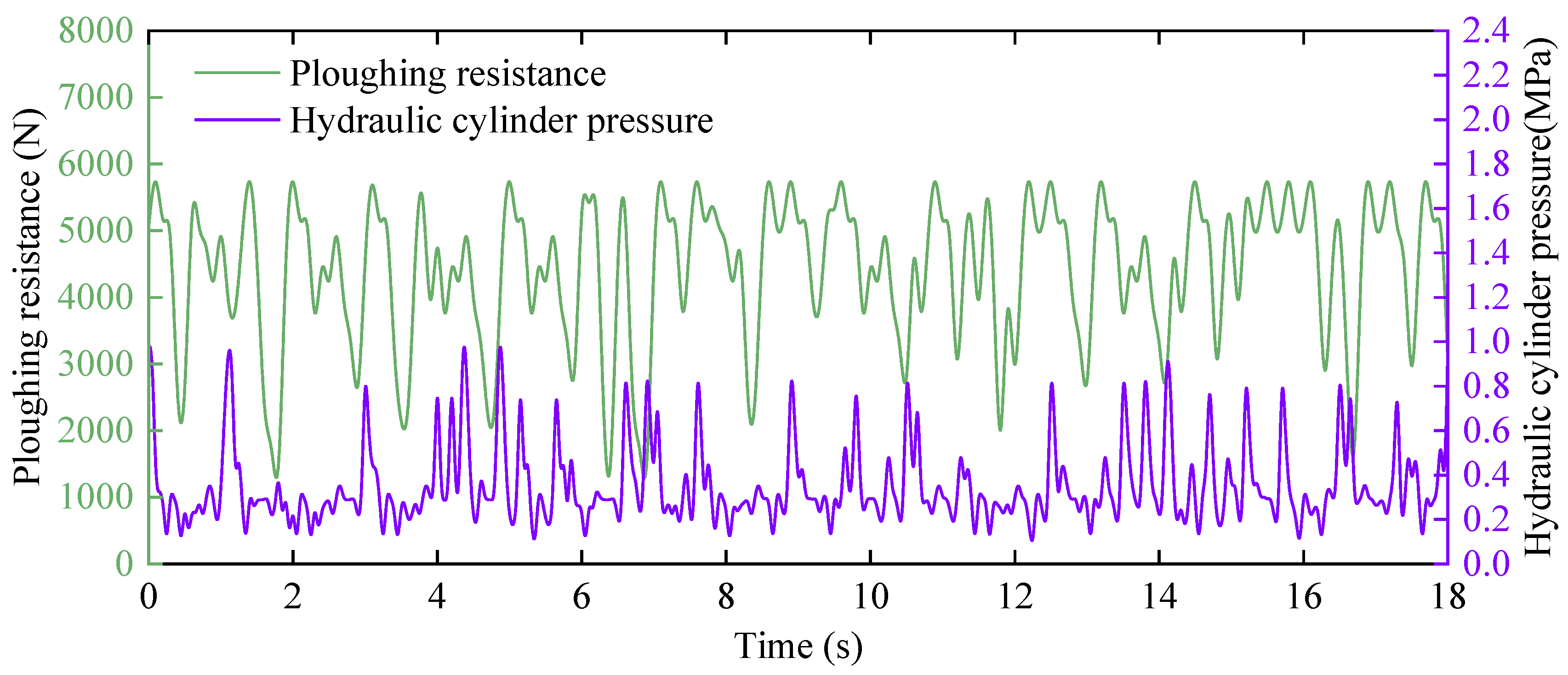
During the simulation, the hydraulic cylinder pressure was varied to adapt to changes in ploughing resistance. This ensured the working stability of the electric tractor while transferring more load from the depth-limiting wheel to the rear driving wheels, thereby optimizing the traction performance.
(2)
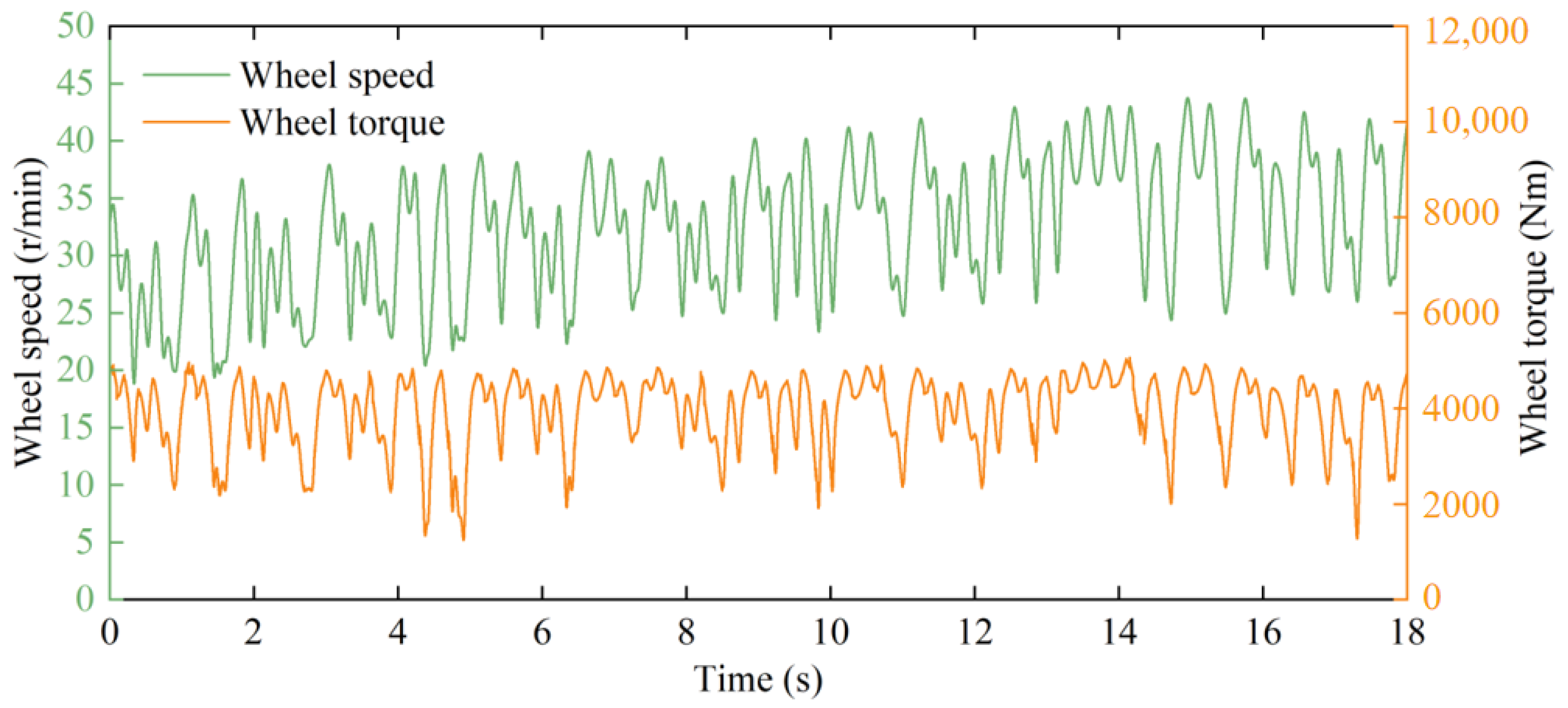
Under the hydraulic cylinder pressure control mode, the traction efficiency of the electric tractor was increased by 2.42%, and wheel slip in the hydraulic cylinder pressure control mode was reduced by 9.27% compared to the traditional position control mode, improving the traction performance of the electric tractor and achieving more efficient traction operations.
(3)
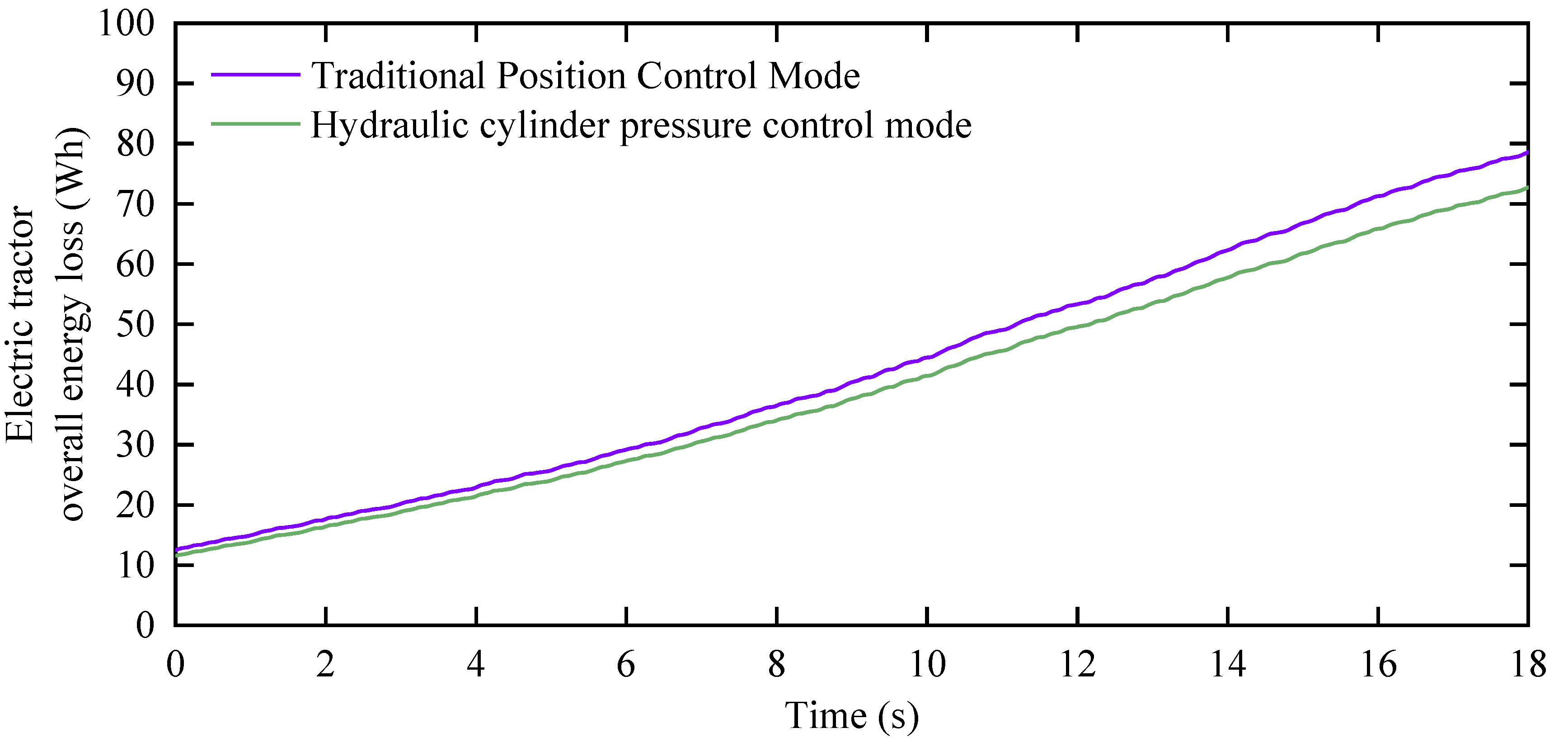
Under the hydraulic cylinder pressure control mode, the electric tractor overall energy loss was reduced by 7.67% compared to the traditional position control mode, and the electric tractor overall efficiency in the hydraulic cylinder pressure control mode was increased by 3.13%, reducing the electric tractor overall energy loss.
(4)
The hydraulic cylinder pressure control method of the electro-hydraulic hitch system proposed in this paper could achieve the purpose of effectively improving traction performance and reducing the electric tractor overall energy loss while maintaining a constant ploughing depth.
The hydraulic cylinder pressure control method proposed in this paper improved the traction performance and overall efficiency of the electric tractor and reduced the wheel slip, which enabled greater traction and endurance compared to the electric tractor of the same power as well as improved the maneuvering stability due to the reduction in the wheel slip.
It is worth stating that the hydraulic cylinder pressure control method proposed in this paper is based on a longitudinal two-dimensional tractor implement system dynamic model, in which the four tires of the tractor were simplified to the front and rear two tires and the effect of the lateral inclination angle, the longitudinal acceleration, and the lateral acceleration on the tire load were neglected in order to reduce the complexity of the optimization problem. These simplifications and assumptions have a subtle effect on the control methodology and simulation comparison results. In addition, although the hydraulic cylinder pressure control method is able to improve the traction performance and reduce the energy loss of electric tractors compared with the traditional position control method, the realization of the pressure control in practical applications requires higher costs and maintenance expenses, and the higher the precision requirements for pressure control, the higher the cost. Therefore, in our future research, we need to balance the accuracy of the pressure control with the efficiency of the machine as well as to refine and improve the dynamic model.

Author Contributions

Conceptualization, B.X.; formal analysis, Z.L.; methodology, J.W. (Jihang Wang) and J.W. (Jing Wu); project administration, S.Z.; software, Z.L.; supervision, Z.C.; validation, Z.C.; writing—original draft, J.W. (Jihang Wang) and J.W. (Jing Wu); writing—review and editing, Z.L. and S.Z. All authors have read and agreed to the published version of the manuscript.

Funding

This work was funded by the National Natural Science Foundation of China (52272444).

Institutional Review Board Statement

Not applicable.

Data Availability Statement

Not applicable.

Conflicts of Interest

The authors declare no conflict of interest.

References

  1. Lebedevas, S.; Makareviciene, V.; Sendzikiene, E.; Zaglinskis, J. Oxidation stability of biofuel containing Camelina sativa oil methyl esters and its impact on energy and environmental indicators of diesel engine. Energy Convers. Manag. 2013, 65, 33–40. [Google Scholar] [CrossRef]
  2. Ushakov, S.; Valland, H.; Æsøy, V. Combustion and emissions characteristics of fish oil fuel in a heavy-duty diesel engine. Energy Convers. Manag. 2013, 65, 228–238. [Google Scholar] [CrossRef]
  3. Labeckas, G.; Slavinskas, S. Comparative performance of direct injection diesel engine operating on ethanol, petrol and rapeseed oil blends. Energy Convers. Manag. 2009, 50, 792–801. [Google Scholar] [CrossRef]
  4. Anselma, P.G.; Belingardi, G. Fuel cell electrified propulsion systems for long-haul heavy-duty trucks: Present and future cost-oriented sizing. Appl. Energy 2022, 321, 119354. [Google Scholar] [CrossRef]
  5. Mileusnić, Z.I.; Petrović, D.V.; Đević, M.S. Comparison of tillage systems according to fuel loss. Energy 2010, 35, 221–228. [Google Scholar] [CrossRef]
  6. Janulevičius, A.; Juostas, A.; Pupinis, G. Tractor’s engine performance and emission characteristics in the process of ploughing. Energy Convers. Manag. 2013, 75, 498–508. [Google Scholar] [CrossRef]
  7. Moinfar, A.; Shahgholi, G.; Gilandeh, Y.A.; Gundoshmian, T.M. The effect of the tractor driving system on its performance and fuel loss. Energy 2020, 202, 117803. [Google Scholar] [CrossRef]
  8. Porteš, P.; Bauer, F.; Čupera, J. Laboratory-experimental verification of calculation of force effects in tractor’s three-point hitch acting on driving wheels. Soil Tillage Res. 2013, 128, 81–90. [Google Scholar] [CrossRef]
  9. Janulevičius, A.; Damanauskas, V. How to select air pressures in the tires of MFWD (mechanical front-wheel drive) tractor to minimize fuel loss for the case of reasonable wheel slip. Energy 2015, 90, 691–700. [Google Scholar] [CrossRef]
  10. Wu, Z.; Wang, J.; Xing, Y.; Li, S.; Yi, J.; Zhao, C. Energy Management of Sowing Unit for Extended-Range Electric Tractor Based on Improved CD-CS Fuzzy Rules. Agriculture 2023, 13, 1303. [Google Scholar] [CrossRef]
  11. Chen, Y.; Chen, L.; Chang, M. A Design of an Unmanned Electric Tractor Platform. Agriculture 2022, 12, 112. [Google Scholar] [CrossRef]
  12. Moreda, G.P.; Muñoz-García, M.A.; Barreiro, P. High voltage electrification of tractor and agricultural machinery—A review. Energy Convers. Manag. 2016, 115, 117–131. [Google Scholar] [CrossRef]
  13. Zhang, S.; Wen, C.; Ren, W.; Luo, Z.; Xie, B.; Zhu, Z.; Chen, Z. A joint control method considering travel speed and slip for reducing energy loss of rear wheel independent drive electric tractor in ploughing. Energy 2023, 263, 126008. [Google Scholar] [CrossRef]
  14. Lagnelöv, O.; Dhillon, S.; Larsson, G.; Nilsson, D.; Larsolle, A.; Hansson, P. Cost analysis of autonomous battery electric field tractors in agriculture. Biosyst. Eng. 2021, 204, 358–376. [Google Scholar] [CrossRef]
  15. Zhou, D.; Ravey, A.; Al-Durra, A.; Gao, F. A comparative study of extremum seeking methods applied to online energy management strategy of fuel cell hybrid electric vehicles. Energy Convers. Manag. 2017, 151, 778–790. [Google Scholar] [CrossRef]
  16. Kumar, S.; Noori, M.T.; Pandey, K.P. Performance characteristics of mode of ballast on energy efficiency indices of agricultural tyre in different terrain condition in controlled soil bin environment. Energy 2019, 182, 48–56. [Google Scholar] [CrossRef]
  17. Pranav, P.K.; Tewari, V.K.; Pandey, K.P.; Jha, K.R. Automatic wheel slip control system in field operations for 2WD tractors. Comput. Electron. Agric. 2012, 84, 1–6. [Google Scholar] [CrossRef]
  18. Zhang, S.; Du, Y.; Zhu, Z.; Mao, E.; Liu, J.; Shi, J. Integrated control method of traction & slip ratio for rear-driving high-powerm tractors. J. Agric. Eng. 2016, 32, 47–53. [Google Scholar]
  19. Shafaei, S.M.; Loghavi, M.; Kamgar, S. A practical effort to equip tractor-implement with fuzzy depth and draft control system. Eng. Agric. Environ. Food 2019, 12, 191–203. [Google Scholar] [CrossRef]
  20. Wu, Z.; Xie, B.; Li, Z.; Chi, R.; Ren, Z.; Du, Y.; Inoue, E.; Mitsuoka, M.; Okayasu, T.; Hirai, Y. Modelling and verification of driving torque management for electric tractor: Dual-mode driving intention interpretation with torque demand restriction. Biosyst. Eng. 2019, 182, 65–83. [Google Scholar] [CrossRef]
  21. Čiplienė, A.; Gurevičius, P.; Janulevičius, A.; Damanauskas, V. Experimental validation of tyre inflation pressure model to reduce fuel loss during soil tillage. Biosyst. Eng. 2019, 186, 45–59. [Google Scholar] [CrossRef]
  22. Shafaei, S.M.; Loghavi, M.; Kamgar, S. Fundamental realization of longitudinal slip efficiency of tractor wheels in a tillage practice. Soil Tillage Res. 2021, 205, 104765. [Google Scholar] [CrossRef]
  23. Lagnelöv, O.; Larsson, G.; Nilsson, D.; Larsolle, A.; Hansson, P. Performance comparison of charging systems for autonomous electric field tractors using dynamic simulation. Biosyst. Eng. 2020, 194, 121–137. [Google Scholar] [CrossRef]
  24. Zhang, S.; Xie, B.; Wen, C.; Zhao, Y.; Du, Y.; Zhu, Z.; Song, Z.; Li, L. Intelligent ballast control system with active load-transfer for electric tractors. Biosyst. Eng. 2022, 215, 143–155. [Google Scholar] [CrossRef]
  25. Ning, P.; Su, K.; Wang, M.; Cui, G.; Li, K.; Cui, Y.; Wang, W. Design and Test of Electric Tractor with Battery Position Longitudinally Adjustable Mechanism. J. Agric. Mech. Res. 2022, 44, 212–218. [Google Scholar] [CrossRef]
  26. Laceklis-Bertmanis, J.; Repsa, E.; Kronbergs, E. Investigation of pressure oscillation in hydraulic hitch-system, Engineering for Rural Development. In Proceedings of the 9th International Scientific Conference on Engineering for Rural Development, Jelgava, Latvia, 27–28 May 2010. [Google Scholar]
  27. Liu, C.; Zhao, J.; Gu, J.; Du, Y.; Li, Z.; Zhu, Z.; Mao, E. Pressure Control Algorithm Based on Adaptive Fuzzy PID with Compensation Correction for the Tractor Electronic Hydraulic Hitch. Appl. Sci. 2020, 10, 3179. [Google Scholar] [CrossRef]
  28. Moitzi, G.; Haas, M.; Wagentristl, H.; Boxberger, J.; Gronauer, A. Energy loss in cultivating and ploughing with traction improvement system and consideration of the rear furrow wheel-load in ploughing. Soil Tillage Res. 2013, 134, 56–60. [Google Scholar] [CrossRef]
  29. Habarta, F. Determination in relation to safety of operation of the minimal load on the front steering axle of a tractor with implements attached. J. Agric. Eng. Res. 1971, 16, 126–140. [Google Scholar] [CrossRef]
Figure 1. Force of the electric tractor implement system.
Agriculture 13 01555 g001
Figure 2. Force analysis diagram of the lift arm.
Agriculture 13 01555 g002
Figure 3. The force analysis diagram of the lower link.
Agriculture 13 01555 g003
Figure 4. Tire–soil interaction schematic.
Agriculture 13 01555 g004
Figure 5. Flowchart for finding the optimal target hydraulic cylinder pressure.
Agriculture 13 01555 g005
Figure 6. Hardware-in-the-loop (HIL) testing platform.
Agriculture 13 01555 g006
Figure 7. Experimental measurement of ploughing resistance for the electric tractor.
Agriculture 13 01555 g007
Figure 8. Variation curve of hydraulic cylinder pressure and ploughing resistance.
Agriculture 13 01555 g008
Figure 9. The variation curve of the wheel slip.
Agriculture 13 01555 g009
Figure 10. The variation curve of the wheel speed and wheel torque under the hydraulic cylinder pressure control mode.
Agriculture 13 01555 g010
Figure 11. The variation curve of the tractor speed under the hydraulic cylinder pressure control mode.
Agriculture 13 01555 g011
Figure 12. The electric tractor overall energy loss curve.
Agriculture 13 01555 g012
Figure 13. The input power and ploughing power curves for both modes.
Agriculture 13 01555 g013
Figure 14. The variation curves of traction efficiency for both modes.
Agriculture 13 01555 g014
Figure 15. Electric tractor overall efficiency for both modes.
Agriculture 13 01555 g015
Table 1. Simulation parameters and values for the tractor.
Parameter Value Parameter Value
m 1 (kg)1260 r 2 (m)0.43
m 2 (kg)120 h 1 (m)0.46
g (kg·s−2)9.8 h 2 (m)0.60
X O 1 (m)0.88 h 3 (m)0.1
X O 2 (m)0.54 X 1 (m)1.50
X a b (m)1.42 X 2 (m)1.38
b 1 (m)0.12 X g (m)0.97
b 2 (m)0.22 X L (m)0.77
r 1 (m)0.25 C I (kPa)1300
Table 2. Power statistics for both modes.
Input Power (kW)
Traditional Position Control Mode Hydraulic Cylinder Pressure Control Mode
Mean25.7724.81
STD9.118.46
Min7.407.27
Max40.9040.90
Disclaimer/Publisher’s Note: The statements, opinions and data contained in all publications are solely those of the individual author(s) and contributor(s) and not of MDPI and/or the editor(s). MDPI and/or the editor(s) disclaim responsibility for any injury to people or property resulting from any ideas, methods, instructions or products referred to in the content.

