Abstract
This study designed a cam-linked planetary gear system automatic seedling picking mechanism to address unstable operation and issues of high damage to the substrate caused by the picking mechanism of the dryland vegetable seedling transplanter. Through an analysis of the kinematic principle of the structure and the establishment of the kinematic model, computer-aided analysis software was developed using Visual Basic 6.0. Consequently, a set of structural parameter values satisfying the target trajectory was derived employing the human–computer interaction method, and the 3D model was designed. The model was imported into Adams for kinematic simulation, and the seedling picking mechanism’s trajectory during the operation was obtained through simulation. Modal analysis of the model was performed using Ansys, and the first six-order modal vibration patterns and modal frequencies of the seedling picking mechanism were obtained under the simulated working environment. The results confirmed that no resonance occurred during the operation. Comparisons of the seedling picking needle trajectory with the idle test revealed that the theoretical, simulated, and test trajectories were approximately identical. This proved the reliability of the theoretical design of the seedling picking mechanism, the machining of the parts, and the test bench construction. The success rates of seedling picking were 97.66, 96.09, 93.75, and 90.63% at 90, 100, 110, and 120 plants/min, respectively, with rates of substrate damage of 4.43%, 6.73%, 9.57%, and 14.37%, respectively. Thus, the experimental results confirmed that the operating parameters of the cam-linked planetary gear system seedling picking mechanism satisfied the design requirements.
1. Introduction
The vegetable industry is one of the important pillar industries of the agricultural and rural economy, and transplanting vegetable seedlings is a key link in vegetable production. Mechanical transplanting technology can effectively solve the problem of seasonal planting while reducing the impact of seasonal changes on crop growth. This ensures the consistency and stability of crop growth [1,2,3]. Currently, semi-automatic transplanting machines are mainly used for transplanting operations in China; however, the manual method of acquiring and dropping seedlings is disadvantageous in terms of the limited speed of acquiring seedlings, the high labor cost, and the high intensity of work, which makes it unsuitable for large-scale vegetable transplanting operations. Therefore, to improve operational efficiency and quality, research and development of a fully automatic transplanter have become an urgent need in the industry. A key technology for fully automatic transplanting is the seedling picking and dropping mechanism, whose structure must be reasonable, stable, and efficient. This challenge has become a priority in the research of transplanter machinery [4,5,6,7]. The replacement of manual seedling picking and dropping with machinery can ensure improvements in the efficiency and quality of transplantation, a reduction in labor costs, and an increase in production efficiency. Therefore, the development of an efficient and stable seedling picking and dropping mechanism is essential to improving vegetable transplanting technology and promoting the development of the vegetable industry [8,9,10,11].
Several scholars have proposed various types of seedling picking and dropping mechanisms to show the different characteristics of seedlings. The fully automatic vegetable transplanter developed by Ferrari®, Italy, used an ejector clamping type seedling picking mechanism, which ensured low damage to the substrate and high picking and dropping efficiency. However, the overall automatic control and pneumatic systems were complicated [12]. Choi et al. [13] (Korea) proposed a simple structure and low manufacturing cost crank-guide chute type seedling picking and dropping mechanism that achieved an 80–90% success rate of seedling picking; however, the chute was prone to wear and tear. Moreover, if the speed of seedling picking increased, the mechanism was subjected to large shocks and vibrations, which reduced the success rate of transplanting. Kang developed a double-row vegetable transplanter with a fork seedling pickup mechanism, and the rate of seedling deficiency in this transplanter was 13.7% [14]. An automatic transplanting mechanism was invented by Shomu Ito of Yanmar Agricultural Machinery. Thus, foreign seedling picking mechanisms have the disadvantages of complex structures and high wear and tear; hence, they cannot be transplanted at high-speed.
In China, the automatic seedling picking mechanism has been studied for a relatively short period. Xu Liming et al. [15] designed a seedling picking mechanism realized via a four-linked rod. Despite its relatively simple structure, its seedling picking rate is not that fast and cannot adapt to the development requirements of automatic vegetable transplanters. Li Hua et al. [16] designed an automatic seedling picking mechanism for pepper seedlings, analyzed the kinematic characteristics of the mechanism, and optimized its structural parameters to obtain a set of automatic seedling picking mechanism parameters that satisfied the agronomic requirements of pepper seedling transplanting. However, owing to the high friction of the curved chute, the picking speed could not satisfy the demand for high-speed transplanting. In the case of the above-mentioned chute-type seedling picking mechanism, Yu Gaohong et al. [17,18,19,20] designed various rotary planetary system seedling picking mechanisms and analyzed their working mechanisms and experimental research. These rotary seedling picking mechanisms used a combination of an incomplete circular gear mechanism and an elliptical gear mechanism or an eccentric gear-non-circular gear mechanism, wherein the combined structure achieved the target trajectory through adjustments to the rotational speed of the seedling picking arm cemented to the output shaft [21]. This design method used a non-circular planetary gear system to achieve a specific seedling picking trajectory and attitude and adjusted its concave and convex parts through repeated trials, which is difficult to optimize and inefficient [22]. Thus, the domestic rotary seedling picking mechanisms are disadvantageous owing to their complex structure, high rigidity impact, and unstable performance.
Considering the shortcomings of the above domestic and foreign seedling picking mechanisms, this study proposes a cam-linkage planetary gear system seedling picking mechanism. Its structure was optimized and mechanically analyzed, which aided in the realization of a simple structure and smoother operation.
2. Materials and Methods
The automatic transplanting machine requires the seedling picking mechanism to insert the seedling tray and pick up the seedling substrate to bring out the seedlings. Subsequently, the seedlings are transported to the top of the planters and pushed such that the seedlings fall into the planters vertically. This completes the action of picking up the seedlings once, and then the seedling picking mechanism repeats the above action to complete the cycle of picking up the seedlings.
To satisfy the above requirements, a cam-linked planetary gear system seedling picking mechanism is proposed in this study. As shown in Figure 1 and Figure 2, the seedling picking mechanism primarily consists of a planetary gear system drive mechanism, a cam-link drive mechanism, and a seedling picking arm. The center of the input shaft was the O point, and the centers of the sun, intermediate, and planetary gears were in a straight line. Further, the sun gear was connected to the input shaft through a bearing, a column was fixed at F point on the sun gear, a rod FG was hinged on the column, and the other end of the rod FG is hinged with the rod EG. In addition, the rod EG was fixed to the rod EH at a certain angle, a roller was hinged at the H point, and a torsion spring was added to ensure that the roller was always in contact with the cam. The cam and the housing were fixed on the input shaft, and the rotation of the input shaft drove the rotation of the cam and the housing, wherein the cam pushed the connecting rod EH to swing during the rotation and subsequently pushed the sun gear to swing through the connecting rod mechanism. The seedling picking arm was fixed to the output shaft, and the seedling clamping and pushing action was performed by the internal cam rocker mechanism.
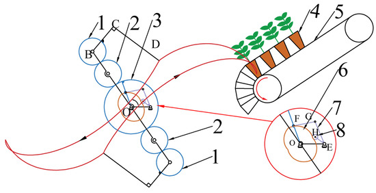
Figure 1.
Sketch of seedling picking mechanism: 1. Planetary gear; 2. Intermediate gear; 3. Sun gear; 4. Seedling tray; 5. Seedling tray delivery mechanism; 6. Cam; 7. Linkage mechanism; and 8. Roller.
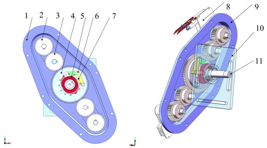
Figure 2.
Cam-linkage planetary gear system seedling picking mechanism: 1. Left housing; 2. Planetary gear; 3. Intermediate gear; 4. Sun gear; 5. Cam; 6. Linkage mechanism; 7. Roller; 8. Seedling picking arm; 9. Right housing; 10. Rack mounting plate; and 11. Input shaft.
In Figure 1, point B is the output shaft axis, C–D is the seedling picking arm, and point O is the input shaft axis. E, F, G, H are the end points of connecting rod FG and connecting rod EH respectively. Where point H is also the axis of the roller.
Figure 3 and Figure 4 show the sketch of the structure of the seedling picking arm and the 3D model, respectively. The fork is hinged on the arm housing through its center of rotation, one end of the fork is in contact with the fork cam, and the other end is connected to the seedling pushing rod, which is fixed in the cavity of the arm as a moving sub. The seedling pushing plate is fixed to the seedling pushing rod, and one end of the seedling picking needle is hinged to the seedling picking arm housing. The seedling picking needle passes through the two holes on the seedling pushing plate, and the opening and closing of the seedling picking needle is controlled by the telescoping of the pushing rod. During the operation, the seedling picking arm rotates clockwise around the cam, and the fork is always pressed against the pushing cam by the spring. The lift and return of the seedling pushing cam control the extension and contraction of the pushing rod, respectively, which in turn controls the opening and closing of the seedling picking needle.
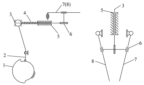
Figure 3.
Sketch of seedling picking arm: 1. Seedling pushing cam; 2. Fork; 3. Seedling pushing rod; spring; 4. Spring; 5. Seedling picking arm housing; 6. Seedling pushing plate; 7. Seedling picking needle; and 8. Seedling picking needle.
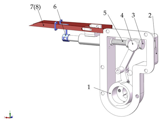
Figure 4.
3D view of the seedling picking arm: 1. Seedling pushing cam; 2. Seedling picking arm housing; 3. Seedling pushing rod; 4. Folk; 5. Spring; 6. Seedling pushing plate; 7. Seedling picking needle; and 8. Seedling picking needle.
The motor drove the input shaft to rotate counterclockwise, whereas the cam and the casing that were fixed to the input shaft rotated in a counterclockwise direction. The sun gear was oscillated by the influence of the cam-linkage, and the engagement drive of the planetary gear system controlled the variable speed rotation of the seedling picking arm fixed to the planetary shaft to achieve the seedling picking trajectory to satisfy the design requirements. The cam designed in this study was divided into two ascending and descending phases with the same curve, each occupying half of the cam. In the ascending phase of the cam and the connecting rod, the sun gear rotated clockwise and increased the clockwise rotation speed of the planetary gear via meshing. In contrast, in the descending phase of the cam, the sun gear rotated counterclockwise and decreased the clockwise rotation speed of the planetary gear via meshing. Thus, the design of the cam profile can be used to achieve the seedling picking trajectory.
To facilitate further optimization of the seedling picking mechanism, the displacement equations of each component of the seedling picking mechanism must be established, with the center of the sun gear in Figure 5 as the coordinate origin, and the horizontal and vertical directions as the X- and Y-axes, respectively. Moreover, in the analysis of its motion model, it was assumed that each component was a rigid structure and no elastic deformation occurred.
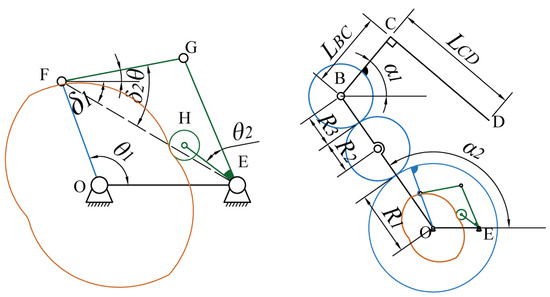
Figure 5.
Structure parameters of seedling picking mechanism.
In Figure 5, point B is the output shaft axis, C–D is the seedling picking arm, and point O is the input shaft axis. E, F, G, H are the end points of connecting rod FG and connecting rod EH respectively. Where point H is also the axis of the roller.
2.1. Kinematic Equations of the Seedling Picking Mechanism
When the seedling picking mechanism begins operation, the planetary frame rotates counterclockwise with an angular velocity of ω. The displacement equation of the planetary gear axis point B is expressed as follows:
where R1 is the radius of engagement of the sun gear; R2 is the radius of engagement of the intermediate gear; R3 is the radius of planetary gear engagement; ω is the angular velocity of rotation of the planetary frame (OB); and α2 is the initial mounting angle of the planetary carrier (OB).
The rotation of the picking arm is combined via two compound motions: the drives of the planetary gear system and the cam-linkage; thus, the displacement equation of the picking needle tip point D can be calculated in two parts as follows:
- 1.
- The displacement equation of the seedling picking tip point driven by the rotation of the planetary frame was analyzed, where the assumption of the sun gear speed is 0. Consequently, the planetary gear and planetary frame transmission ratios can be derived as follows:
To realize the cycle of picking action, the position of the seedling picking arm should be the same as the initial position after one rotation of the planetary frame; thus, the value of i3H should be a negative integer. The ratio of the planetary gear drive was set to planetary frame speed i3H = −1, that is, R3 = 0.5R1. Thus, the planetary frame rotated counterclockwise around the axis of the input shaft for one week, whereas the pick-up arm rotated clockwise around the axis of the planetary shaft for one week.
- 2.
- The rotation speed of the sun gear, driven by the cam-linkage through the gear mesh, was analyzed and then driven by the seedling picking arm. The rotation angle of the sun gear was set as shown in Equation (4), which indicated that the rotation was divided into four stages corresponding to the two ascending and descending stages of the cam. Further, the total rotation angle of one ascending and descending stage was 180°, that is, β3 + β4 = π.
Owing to the characteristics of the cam, the angle of rotation of the sun gear in the cam lift section was equal in size and opposite in direction to the angle of rotation of the sun gear in the cam return section, thus satisfying β1 ∙ ω ∙ (β3/ω) = β2 ∙ ω ∙ (β4/ω), i.e., β1 β3 = β2 β4.
Subsequently, the above two parts can be combined to obtain the equation for the displacement of points C and D as follows:
In the equation, LBC is the length of the BC section of the seedling arm, α1 is the initial installation angle of the BC section of the seedling picking arm, and LCD is the length of the CD segment of the seedling picking arm.
By obtaining the displacement equation at point D, the trajectory of the tip of the seedling picking needle during the movement can be obtained. Thus, each relevant parameter can be optimized according to different trajectories.
The above displacement equation can be used to obtain the trajectory of the tip of the seedling picking needle. Therefore, the next step is to design the cam profile using the analytical method. The displacement equation of the sun gear can be used to obtain the displacement equation of each point in the linkage mechanism driving the sun gear, and the cam profile curve can be designed by the displacement equation at the H point.
The displacement equation of each point in the linkage mechanism is expressed as follows:
where LOF is the length of the connecting rod OF; LFG is the length of the connecting rod FG; LEH is the length of the connecting rod EH; LEG is the length of the connecting rod EG; LEF is the distance between EFs in the graph; θ is the initial installation angle of the connecting rod FG; θ1—initial installation angle of the connecting rod OF; θ2 is the angle between the EG rod and the EH rod; δ is the angle of rotation of the E point; δ1 is the acute angle between EF and the horizontal direction; and δ2 is the angle between the EF and FG rod.
As shown in Figure 6, the center of the cam, point O, was the origin of the coordinate axis, and the line between point O and the axis of the oscillating pusher, E, was the x-axis. Further, EH was the initial position of the pendulum. If the cam was fixed, point E was rotated clockwise around center O, and point H was swung relative to point E according to the above displacement equation. Subsequently, the motion curve of point H was recorded after one week of rotation of point E to derive the profile curve of the cam. The displacement equation for the clockwise rotation of point H around point O is as follows:
where φ is the angular displacement of the pendulum EH angular displacement, and φ0 is the initial installation angle of the pendulum EH.
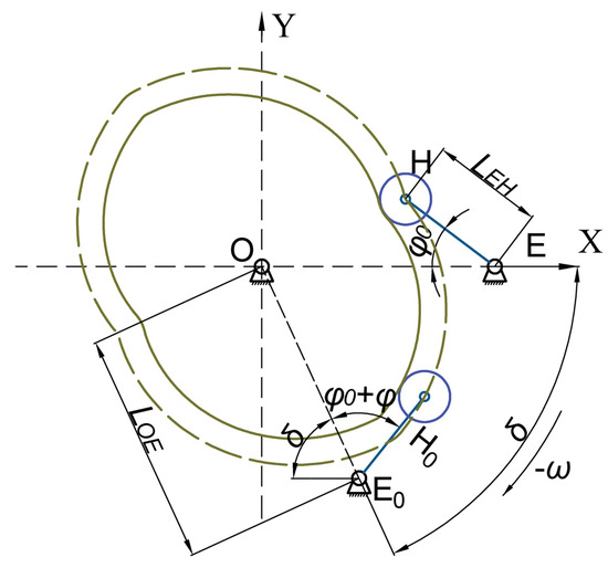
Figure 6.
Pendulum–cam contour line design.
2.2. Optimization Objectives and Variables
After reviewing the relevant literature, to improve the success rate of the seedling picking mechanism and adapt it to the characteristics of a variety of vegetables in the seedling tray, the trajectory of the seedling picking mechanism must be optimized. The optimization objectives include the following five points [17,23].
- The trajectory of the withdrawal of the seedling needle from the seedling tray should be approximately straight, and as vertical as possible with the cavity tray. The attitude of the withdrawal arm should remain unchanged. Further, the length of the straight section of the withdrawal trajectory should not be less than that of the seedling tray; otherwise, the seedling tray interferes with the seedling feeding mechanism.
- To ensure the success rate during the process of seedling picking, the tip of the seedling picking needle should be inserted into the seedling substrate of the seedling tray at a depth of not less than 35 mm. Moreover, it should not collide with the cavity tray.
- The minimum distance between the two pick-up arms during operation should be greater than 20 mm to ensure that the potted seedling does not interfere with the other pick-up arm when holding the seedling.
- When inserting the seedling needle into the cavity tray, the angle between the seedling needle and seedling should be in the range of 10–30° to ensure that the seedling needle does not cause damage when inserting the seedling into the pot. Moreover, this also ensures that it does not damage the stem and leaves of the seedling.
- To not collide with the wall of the seedling tray during seedling picking, the width of the loop of the seedling picking track should be less than 10 mm, which can reduce the damage of the seedling picking targeting the substrate.
2.3. Optimization Results
In this study, the Visual Basic 6.0 visual development platform was used to develop the auxiliary analysis software for the seedling picking mechanism of the seedling tray based on the above kinematic equations. The parameters of the seedling picking mechanism were optimized through a human–computer interaction optimization method and then gradually adjusted to ensure that the output parameters obtained conformed to the range of the target parameters.
Figure 7 shows the interface of the computer-aided analysis and optimization of the seedling picking mechanism, which is divided into four main areas: the input area of the structural parameters, the dynamic display area of the seedling picking mechanism, the output area of the target parameters, and the cam profile design area. This software can display the motion status of the seedling picking mechanism in real-time and determine the law of influence of each parameter on the trajectory through adjustments to individual parameters.
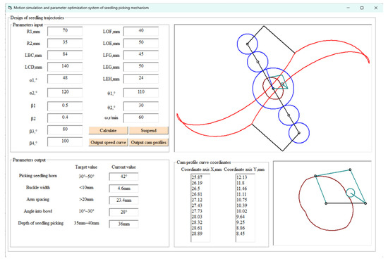
Figure 7.
Optimization interface of the trajectory of the seedling picking mechanism.
In Figure 7 the red line represents the movement of the seedling picking needle, the blue circle represents the gear, the brown curve represents the cam, and the green line represents the connecting rod and roller.
Figure 8 shows the optimization process for the seedling picking trajectory. The human–computer interaction method was used to design the parameters of the seedling picking mechanism, and a set of trajectories conforming to the target parameters was obtained via continuous adjustments to each structural parameter. The optimal structural parameters were obtained as listed in Table 1. The optimized target parameters were as follows: seedling pickup angle of 42°, loop width of 4.6 mm, pickup arm spacing of 23.4 mm, entry angle of 28°, and seedling depth of 36 mm. It is evident that the optimized target parameters fully satisfied the design requirements of the seedling pickup mechanism.
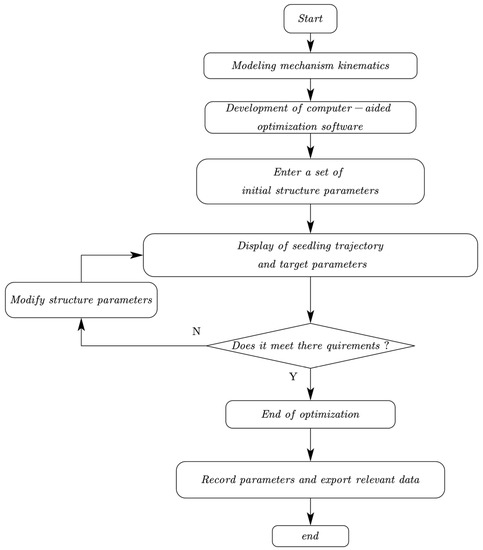
Figure 8.
Flow chart of structural parameter optimization.

Table 1.
Final structure parameters.
3. Simulation and Analysis of Seedling Picking Mechanism
3.1. Kinematic Simulation of Seedling Picking Mechanism
The modeling of the seedling picking mechanism was carried out according to the above structural parameters. As the 3D solid modeling module provided by Adams is not suitable for the creation of complex 3D models, SolidWorks software was used for modeling. In order to determine the accuracy of the theoretical design and 3D modeling, the kinematic simulation of the model is required, and the obtained simulated seedling retrieval trajectory is compared with the theoretical one.
The model was converted into an intermediate format (Parasolid) and imported into Adams, which was followed by a kinematic simulation of the seedling picking mechanism.
In the model imported into Adams, the material parameters listed in Table 2 were added to each part, and the constraints and kinematic pairs were re-added to each part. To render the simulation more consistent with the actual situation, the Solid to Solid contact force method was used to simulate the transmission between the gears and the cam-linkage. This method can calculate the force between the entities and thus simulate the actual force situation, thereby making the simulation more consistent with the actual operation movement.
Table 2.
Material Properties.
The efficiency of the seedling picking mechanism is greater than 90 plants/minute in order to meet the high-speed transplanting operation, so this paper will conduct verification tests on the seedling picking mechanism at an efficiency of 90 plants/min to 120 plants/min. Since the greater the efficiency, the more unstable the operation of the seedling picking mechanism is, the trajectory of the seedling picking mechanism at maximum efficiency is obtained by simulation. As shown in Figure 9, the trajectory of the seedling picking point following the simulation was approximately identical to that of the theoretical trajectory. This demonstrated the reliability of the theoretical design.
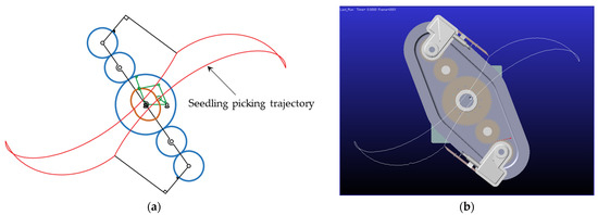
Figure 9.
Comparison of trajectory curves: (a) Theoretical trajectory; (b) Simulation Trajectory.
3.2. Modal Analysis of Seedling Picking Mechanism
For the finite element analysis of the drive mechanism (gears, connecting rods, cams, etc.) in the seedling picking mechanism, the 3D model created using SW was imported into Ansys in stp format. To reduce the calculation volume, the mechanism was simplified and the constraints were redefined while ensuring the calculation accuracy. After that, the structure was meshed, and the meshed mechanism comprised 230,927 cells and 1,049,484 nodes; the meshed model is shown in Figure 10. The overall quality of the mesh of the seedling picking mechanism was in the range of 0.85–1, indicating that the mesh quality was up to standard and satisfied the requirements. Based on the parameters listed in Table 2, the parts of the seedling picking mechanism were set, and the frame fixing plate was set to be fixed to the ground.
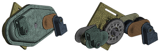
Figure 10.
Grid model of seedling picking mechanism.
In this study, the modal analysis of the seedling picking mechanism was carried out by means of finite element analysis, and the first six orders of modal vibration and modal frequencies of the seedling picking mechanism were simulated, and the modal frequencies were compared with the engagement frequencies of the planetary gear system to determine whether resonance would occur.
Table 3 shows the first six-order modal frequencies of the seedling picking mechanism in the working process. The seedling picking mechanism produces vibration when it is working. In general, the higher-order modal is not easy to reach, and the primary influence on the mechanism is the lower-order modal; thus, only the first six-order intrinsic frequency results of the structure and the corresponding formation can be extracted. The first six-order modal frequencies are presented in Table 3, and the first six-order modal vibration patterns are shown in Figure 11. In the actual working process, the modal frequencies of the seedling mechanism should be avoided, particularly the first and second-order frequencies.
Table 3.
The first Sixth-order modal frequency of the seedling picking mechanism.
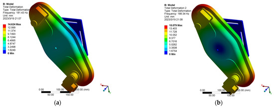
Figure 11.
The first sixth-order mode vibration pattern of the seedling picking mechanism: (a) First-order modal vibration pattern; (b) Second-order modal vibration pattern; (c) Third-order modal vibration pattern; (d) Fourth-order modal vibration pattern; (e) Fifth order modal vibration pattern; (f) and Sixth-order modal vibration pattern.
The frequency of meshing of the planetary gear train is [24,25] as follows:
where n is the sun gear speed; nb is the speed of the planetary carrier; and z is the number of teeth of the sun gear.
When the seedling picking efficiency is 120 plants/min, the rotation of the sun gear was divided into two speeds, and the meshing frequencies of the planetary gear system were calculated using Equation (17); the values were 42 and 105 Hz. From Table 3, it is evident that the first six orders of the inherent frequencies of the seedling picking mechanism were in the range of 181.43–678.14 Hz, which were much larger than the meshing frequencies of the planetary gear system. Thus, the resonance phenomenon did not occur during the efficiency of seedling picking at less than 120 plants/min.
4. Experiment and Analysis
4.1. Verification of the Trajectory of the Seedling Picking Mechanism
As shown in Figure 12a, a test bench was built to further verify the practical feasibility and reliability of the working performance of the proposed mechanism. Considering the operational parameters, the efficiency of seedling picking was set to 120 plants/min. Through the application of a high-speed camera to shoot and process the video of the idling process, the motion trajectory of the tip of the seedling picking needle was obtained, and the test trajectory was compared with the simulated and theoretical trajectories. As evident, the motion trajectory of the prototype was approximately identical to that of the simulated trajectory, thus verifying the feasibility of the structure and the reliability of the design method.
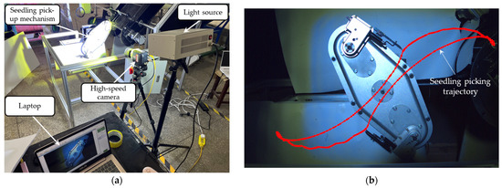
Figure 12.
Idle test: (a) Idle test device; (b) Test trajectory.
4.2. Analysis of Seedling Picking Tests by Seedling Picking Institutions
To verify the practicality of this mechanism, seedling picking experiments were conducted on 128 seedling trays. Figure 13 shows the pepper seedlings used in the experiment and the test bed built for seedling picking. The seedlings were made from “Killing Flame No. 2 pepper seedlings” bred by Luoyang Chengyan Chili Pepper Research Institute, which were 45 days old and 8–12 cm tall. Seedling tray with 128 holes, an overall size of 540 mm × 280 mm, a square cross-section of holes, inverted trapezoid longitudinal section, upper diameter of 32 mm, lower diameter of 13 mm, and height of 42 mm. The main components of the cavity tray substrate were grass charcoal, vermiculite, and perlite mixed in a ratio of 6:3:1, and the moisture content of the substrate was 60%. As the operating efficiency of the high-speed transplanter must be above 90 plants/min in the “Dryland Planting Machinery,” the test was divided into four groups according to the seedling picking efficiencies of 90, 100, 110, and 120 plants/min. In this experiment, the success rate of seedling picking (Y1) and the rate of substrate fragmentation (Y2) were used as the evaluation indices of the seedling picking effect. The calculation formula was as follows:
where n is the total number of effective potted seedlings for the experiment; n1 is the total number of potted seedlings successfully removed and vertically dropped at the drop point; m is the total mass of the substrate before picking seedlings; and m1 is the total mass of the substrate after successful seedling picking.
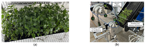
Figure 13.
Pepper seedling sampling test: (a) A tray with 128 pepper seedlings; (b) Seedling picking test bench.
In the experiment, an electronic scale with an accuracy of 0.1 g was used to measure the substrate before and after seedling picking, and the substrate fragmentation rate of the picking process was calculated using Equation (19). Further, the success of seedling picking was determined by reaching the seedling drop point and vertically dropping the potted seedlings.
As presented in Table 4 and Figure 14, when the efficiency of seedling picking was 90, 100, 110, and 120 plants/min, the success rates of seedling picking were 97.66%, 96.09%, 93.75%, and 90.63%, respectively. In addition, the rates of substrate damage were 4.43%, 6.73%, 9.57%, and 14.37%, respectively. As the efficiency of seedling picking increases, the success rate of seedling picking decreases, and substrate damage increases. This is because as the seedling picking efficiency increases, the speed of the seedling picking arm when inserted into the cavity tray also increases, causing more impact and damage to the substrate, resulting in unstable seedling clamping and thus reducing the success rate; as the seedling picking efficiency increases, the impact between the cam and the connecting rod increases, causing the seedling picking arm to vibrate when performing variable speed.
Table 4.
Results of the seedling sampling test of pepper seedlings.
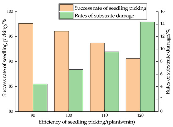
Figure 14.
Results of seedling sampling test.
5. Conclusions
- This study proposed a seedling picking mechanism for a cam-linked planetary gear system, analyzed its working principle and structural characteristics, established the kinematic model of the mechanism, and developed computer-aided design optimization software through VB. Further, a set of structural parameters satisfying the target parameters was derived through human–computer interaction, and three-dimensional modeling was conducted according to the parameters. The motion of the seedling picking mechanism was simulated using Adams, and the simulated trajectory of the tip of the seedling picking needle was compared with the theoretical trajectory to verify the feasibility of the theoretical design.
- Ansys was used to perform finite element analysis on the model of the seedling picking mechanism. Through comparisons of the meshing frequency of the gear with the modal frequency, the analysis found that the meshing frequency of the gear was far away from the first six-order modal frequencies of the seedling picking mechanism, which proved that the seedling picking mechanism did not produce resonance under the working condition of 120 plants/min.
- A test bench for the seedling picking mechanism was built, and an idle experiment was conducted to compare the theoretical, simulated, and actual trajectories to verify the reliability of the theoretical design. Thereafter, a seedling picking test was conducted. With an increase in speed, the success rate of seedling picking decreased and the rate of substrate fragmentation increased. Thus, the results showed that the seedling picking mechanism yielded good results and met the design requirements.
Author Contributions
Conceptualization, X.J.; methodology, B.Z.; software, B.Z.; validation, X.J., B.Z. and H.S.; formal analysis, B.Z.; investigation, J.J.; resources, J.J.; data curation, C.L.; writing—original draft preparation, B.Z.; writing—review and editing, X.J.; visualization, X.X.; supervision, X.J.; project administration, J.J.; funding acquisition, X.J. All authors have read and agreed to the published version of the manuscript.
Funding
This research was funded by the National Key R&D Program Topics, grant number 2022YFD2001205; the Henan Provincial Natural Science Foundation Outstanding Youth Fund Project, grant number 202300410124; and the Ministry of Industry and Information Technology Special Project for Industrial Base Re-engineering and High Quality Development of Manufacturing Industry.
Institutional Review Board Statement
Not applicable.
Data Availability Statement
The data are available within the article.
Conflicts of Interest
The authors declare no conflict of interest.
References
- Cui, W.; Zhao, L.; Liu, L.J.; Liu, Z.J.; Zhao, J.H.; Zhao, Z.B. Kinematic analysis and experiment of rotary pick-up mechanism on seedling pick-up device. J. Agric. Mach. 2020, 51, 79–84. [Google Scholar]
- Xue, X.; Li, L.; Xu, C.; Li, E.; Wang, Y. Optimized design and experiment of a fully automated potted cotton seedling transplanting mechanism. Int. J. Agric. Biol. Eng. 2020, 13, 111–117. [Google Scholar] [CrossRef]
- Zhou, M.; Shan, Y.; Xue, X.; Yin, D. Theoretical analysis and development of a mechanism with punching device for transplanting potted vegetable seedlings. Int. J. Agric. Biol. Eng. 2020, 13, 85–92. [Google Scholar] [CrossRef]
- Yao, S.S.; Liu, J.X.; Zeng, J.X.; Shi, Q.; Zhao, C.Y.; He, X. Design of taking-combined-with-vibration-type seedlings unloading mechanism of vegetable transplanter. Agric. Equip. Veh. Eng. 2020, 60, 70–73. [Google Scholar]
- Zhang, Z.G.; Cao, W.B.; Wang, Q.; Zhang, P. Development status and prospect of plug seedlings automatic transplanting machine. Agric. Mech. Res. 2013, 35, 237–241. [Google Scholar]
- Hu, M.J.; Yin, W.Q.; Hu, F.; Qian, Y. Development of test system for automatic pick-up plug seedlings. J. Nanjing Agric. Univ. 2011, 34, 122–126. [Google Scholar]
- Han, C.J.; Yang, W.Z.; Zhang, X.J.; Guo, H.; Yin, W.Q. Design and test of automatic feed system for tray seedlings transplanter. J. Agric. Eng. 2013, 29, 51–61. [Google Scholar]
- Feng, S.J.; Wu, M.L.; Yan, B.; Quan, W. Research status and prospect of seedling pick-up device of pot seedling transplanter. Agric. Mech. Res. 2020, 42, 1–9. [Google Scholar]
- Ji, J.T.; Cheng, Q.; Jin, X.; Zhang, Z.H.; Xie, X.L.; Li, M.Y. Design and test of 2ZLX-2 transplanting machine for oil peony. Int. J. Agric. Biol. Eng. 2020, 13, 61–69. [Google Scholar] [CrossRef]
- Ji, J.; Cheng, Q.; Zhao, B.; Ji, J.T.; Li, M.Y. Design and test of 2ZYM-2 potted vegetable seedlings transplanting machine. Int. J. Agric. Biol. Eng. 2020, 13, 101–110. [Google Scholar]
- Zhou, M.L.; Hua, Z.Y.; Wang, J.Y.; Wang, L.; Zhao, Y.; Yin, D.Q. New type of transverse moving box mechanism for pot seedling transplanting machine. Int. J. Agric. Biol. Eng. 2018, 11, 70–75. [Google Scholar] [CrossRef]
- Wang, M.M.; Song, J.S.; Liu, C.L.; Wang, Y.L.; Sun, Y.P. Design and experiment of crank rocker type clamp seedlings mechanism of vegetable transplanter. J. Agric. Eng. 2015, 31, 49–57. [Google Scholar]
- Choi, W.C.; Kim, D.C.; Ryu, L.H.; Kim, K.U. Development of a seedling pick–up device for vegetable transplanters. Trans. ASAE 2002, 45, 13. [Google Scholar]
- Kang, T.G.; Kim, Y.K.; Jun, H.J.; Choi, L.S. Analysis of pick-up mechanism for automatic transplanter (I). J. Agric. Life Sci. 2017, 51, 187–192. [Google Scholar] [CrossRef]
- Xu, L.M.; Zhang, T.Z.; Shi, Z.Q. Design on the picking seedling machinery in the maize auto-transplanter. J. China Agric. Univ. 2000, 5, 58–60. [Google Scholar]
- Li, H.; Cao, W.B.; Li, S.F.; Fu, W.; Liu, K.Q. Kinematic analysis and test on automatic pick-up mechanism for chili plug seedling. J. Agric. Eng. 2015, 31, 20–27. [Google Scholar]
- Yu, G.H.; Liu, B.H.; Zhao, Y.; Sun, L.; Xie, Y.L. Kinematic principle analysis of transplanting mechanism with planetary elliptic gears in automatic vegetable transplanter. J. Agric. Mach. 2011, 42, 53–57. [Google Scholar]
- Yu, G.H.; Chen, Z.W.; Zhao, Y.; Sun, L.; Ye, B.L. Study on vegetable plug seedling pick-up mechanism of planetary gear train with ellipse gears and incomplete non-circular gear. J. Mech. Eng. 2012, 48, 32–39. [Google Scholar] [CrossRef]
- Tong, J.H.; Yu, G.H.; Zhu, Y.P.; Ye, B.L.; Zheng, C.; Huang, J.H. Design and experiment of three-arms rotary vegetable plug seedling pick-up mechanism. J. Agric. Mach. 2019, 50, 113–121. [Google Scholar]
- Ye, B.L.; Yu, G.H.; Chen, Z.W.; Zhao, Y. Kinematics modeling and parameters optimization of seedling pick-up mechanism of planetary gear train with eccentric gear and non-circular gear. J. Agric. Eng. 2011, 27, 7–12. [Google Scholar]
- Ye, B.L.; Li, L.; Yu, G.H.L.; Liu, A.; Zhao, Y. Dynamics analysis and test of rotary pick-up mechanism for vegetable pot-seedling. J. Agric. Mach. 2014, 45, 70–78. [Google Scholar]
- Liu, J.G.; Yu, G.H.; Tong, Z.P.; Hua, Y. Design and experimental study of a planetary gearing mechanism based on twice unequal amplitude transmission ratio. Int. J. Agric. Biol. Eng. 2022, 15, 155–163. [Google Scholar] [CrossRef]
- Yu, G.H.; Yu, T.F.; Ye, B.L.; Hu, H.J.; Wang, L.W. Design of a rotary plug seedling pick-up mechanism. J. Mech. Eng. 2015, 51, 67–76. [Google Scholar] [CrossRef]
- Xiang, L.; Zhao, Y.; Liu, L.L. Modal analysis of a certain loader gearbox. S. Agric. Mach. 2022, 53, 134–136. [Google Scholar]
- Guo, H.W.; Chen, C.Z. Modal analysis for transmission of a pure electric vehicle. Noise Vib. Control 2018, 38, 388–391. [Google Scholar]


Disclaimer/Publisher’s Note: The statements, opinions and data contained in all publications are solely those of the individual author(s) and contributor(s) and not of MDPI and/or the editor(s). MDPI and/or the editor(s) disclaim responsibility for any injury to people or property resulting from any ideas, methods, instructions or products referred to in the content. |
© 2023 by the authors. Licensee MDPI, Basel, Switzerland. This article is an open access article distributed under the terms and conditions of the Creative Commons Attribution (CC BY) license (https://creativecommons.org/licenses/by/4.0/).