Article

Design and Experiment of a Fully Automatic Plate Lifting Machine for Rice Hard Disk Seedling Cultivation

College of Engineering, Heilongjiang Bayi Agricultural University, Daqing 163319, China
*
Author to whom correspondence should be addressed.
Agriculture 2023, 13(10), 1929; https://doi.org/10.3390/agriculture13101929
Submission received: 7 September 2023 / Revised: 27 September 2023 / Accepted: 29 September 2023 / Published: 1 October 2023
(This article belongs to the Section Agricultural Technology)

Abstract

:
To mitigate the challenges associated with labor intensity and labor expenses in the rice seedling-raising process within greenhouses located in northern China, a comprehensive solution was developed in the form of a completely automated rice seedling-raising machine. The investigation of the first procedure was carried out through the utilization of EDEM software to ascertain the most favorable range of parameters. Performance tests were conducted on the automatic lifting machine designed for rice hard disk seedling cultivation. Based on the findings of the regression model, it can be inferred that when the rake angle is set at 21.278°, the locomotive speed is 0.333 m/s, and the longitudinal conveyor speed is 0.17 m/s, the completeness rate of seed trays reaches 99.48%. Additionally, the lifting efficiency is measured at 510 trays per hour, while the disk jam rate stands at 0.4%. These results indicate that the lifting machine satisfies the specified requirements.

1. Introduction

Rice plays a significant role in China’s food production and food security as it is one of the country’s four primary staple foods. The amount of mechanization in rice production has surpassed 98%. Presently, our approach involves utilizing the method of dark-room seedling rearing with stacked discs [1]. We effectively employ hard-disk seedling-rearing discs and position them within a dark room that maintains a consistent temperature. The utilization of hard disk and dark-room seedling growing methodologies is deemed more appropriate for assembly line operations, hence establishing a robust practical framework for the realization of factory-based seedling rearing [2,3,4,5]. The primary method employed for rice harvesting is manual labor, which necessitates strenuous work within the confines of a greenhouse. Consequently, this approach incurs escalating labor expenses on an annual basis [6]. To enhance the efficiency of rice breeding through the utilization of rigid trays in rice greenhouses and mitigate the labor-intensive nature of the process, it is imperative to devise an automated tray-lifting mechanism that facilitates the automatic provision of seedlings from the trays. Simultaneously, to enhance automation and production efficiency in the rice hard-disk seedling cultivation stage, as well as alleviate labor intensity, an automatic initiation apparatus has been devised to achieve the automated initiation of hard-disk seedling cultivation. The aforementioned findings hold significant implications in the context of achieving full mechanization in rice farming [7,8].
In recent times, there has been a surge in academic investigations of automatic rice seedling production devices, both on a national and international scale. For instance, the Netherlands-based Visser Company has developed a precise automated product line that incorporates automatic rice seedling production devices capable of accommodating various sizes of seedling trays. This system boasts an impressive efficiency rate of up to 1250 trays per hour [9]. The limited use of automated assembly lines in China can be attributed to their expensive cost and the focus of European and American countries on developing such systems for crops or flowers [10,11]. The advancement of rice seedling cultivating technology in Japan has reached a significant level of maturity, as evidenced by the disclosure of multiple patents on automatic disc-feeding equipment [12,13,14,15,16]. The indoor rice seedling cultivation facilities created by businesses such as Kubota [17] and Yangma [18,19] are comprehensive and exhibit a high level of automation in cultivating rice seedlings within a controlled environment. The automated disc feeding system exhibits a higher degree of precision and complexity, boasting an efficiency exceeding 1000 discs per hour. Nevertheless, the exorbitant expenses associated with importing the complete set of equipment and its limited compatibility solely with floppy disks render it incompatible with the modern demands of hard drive startups. Automatic rice seedling tray feeding device manufactured by Taiwan, China Yixiang Enterprise Co., Ltd, exhibits notable attributes such as rapid speed and exceptional efficiency. However, due to its intricate structure and extensive spatial requirements, it has only been adopted by a few larger seedling breeding companies. Consequently, its applicability to standard greenhouse operations is limited [20,21,22]. The proposal put out by the Nanjing Institute of Agricultural Mechanization introduces an automated disc feeder designed to be utilized with disc seedling and sowing machinery. The system employs a motorized cam mechanism to provide the seedling tray with intermittent and automated supply. The device exhibits a straightforward configuration. It operates by utilizing the same power source as the conveying and sowing components of the sowing equipment, thereby ensuring synchronization between the disc feeder and the sowing rhythm. However, its applicability is restricted to power seeders that are specifically equipped for this purpose, imposing notable constraints. In their study, Haibo et al. devised a mechanism for a double-layer seedling tray. This mechanism utilizes the lateral compression travel switch of the traveling seedling tray to generate a level signal. This signal then drives the expansion and retraction of the piston rod support plate of the supporting cylinder. The ultimate goal of this mechanism is to facilitate the dropping and feeding of the seedling tray. The primary objective of this mechanism is to achieve precise alignment between the seed feeding points of the seedling tray hole and the air suction roller suction hole. However, due to its limitation of accommodating only two seedling trays simultaneously, the efficiency is relatively low. In response to this issue, Yongwei et al. [23] introduced an automatic feeding device for rice trays. This device effectively manages the extension and retraction of the upper and lower cylinder guide rods, enabling the automated feeding of rice trays. Nevertheless, the system is currently in preliminary development and lacks any empirical prototype implementation.
This research presents a solution to the aforementioned challenges by proposing the development of a completely automated rice seedling cultivation apparatus utilizing hard drives. The objective of this study is to develop an automated lifting device for rice seedlings in rice greenhouses. This will be achieved through theoretical analysis of essential components and experimental research on the entire machine. The device is intended to have a simplified structure, lower labor costs, and dependable operation. The ultimate goal is to decrease labor intensity and enhance production efficiency in lifting rice seedlings.

2. Materials and Methods

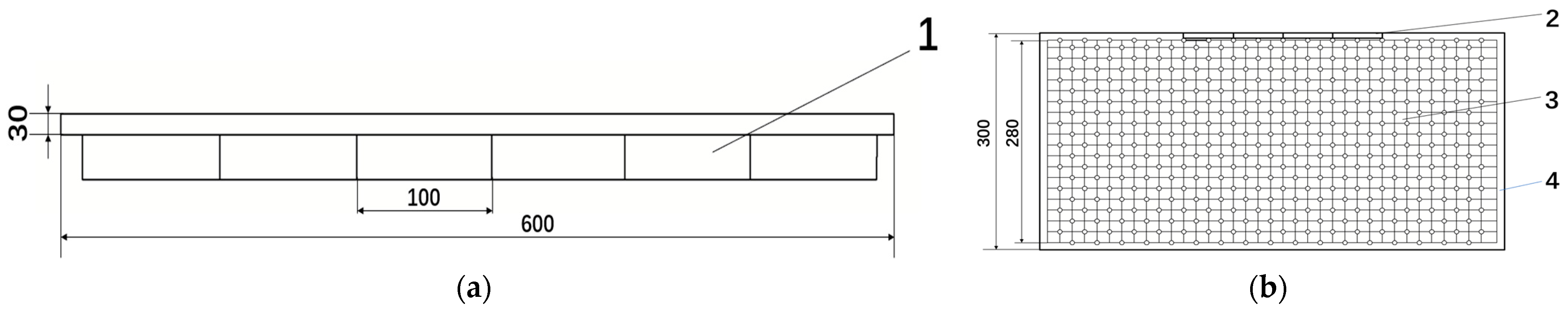
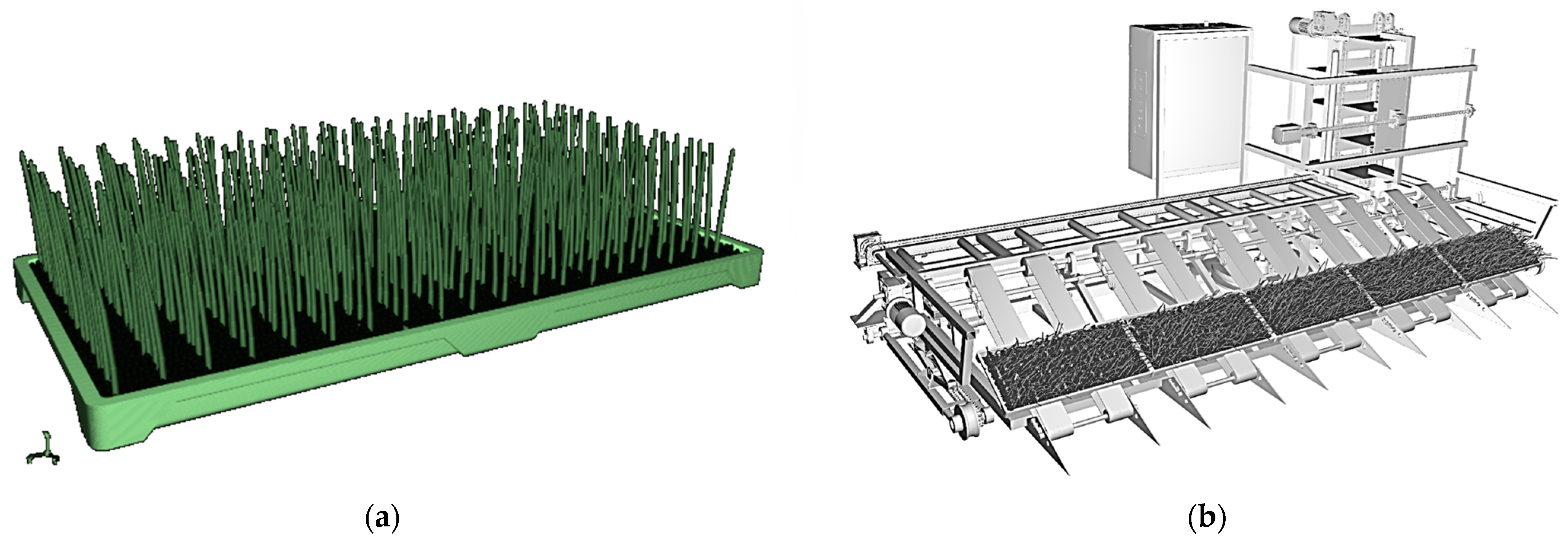
2.1. Material Structure of Rice Seedling Tray

The seedling tray typically employed in implementing stacked darkroom seedling cultivation technology is a rigid seedling tray measuring 600 mm × 300 mm × 30 mm. It comprises a tray bottom, protecting edge, flanging, and reinforcing ribs. The protective edge exhibits an outward flanging configuration, accompanied by the presence of many reinforcing ribs that are strategically positioned. Hard seedling trays are made of polyethylene, polypropylene, and their mixtures, each weighing approximately 650 g and possessing a certain resistance to rolling, trampling, and bending. The schematic representation of the seedling tray’s structure is depicted in Figure 1.

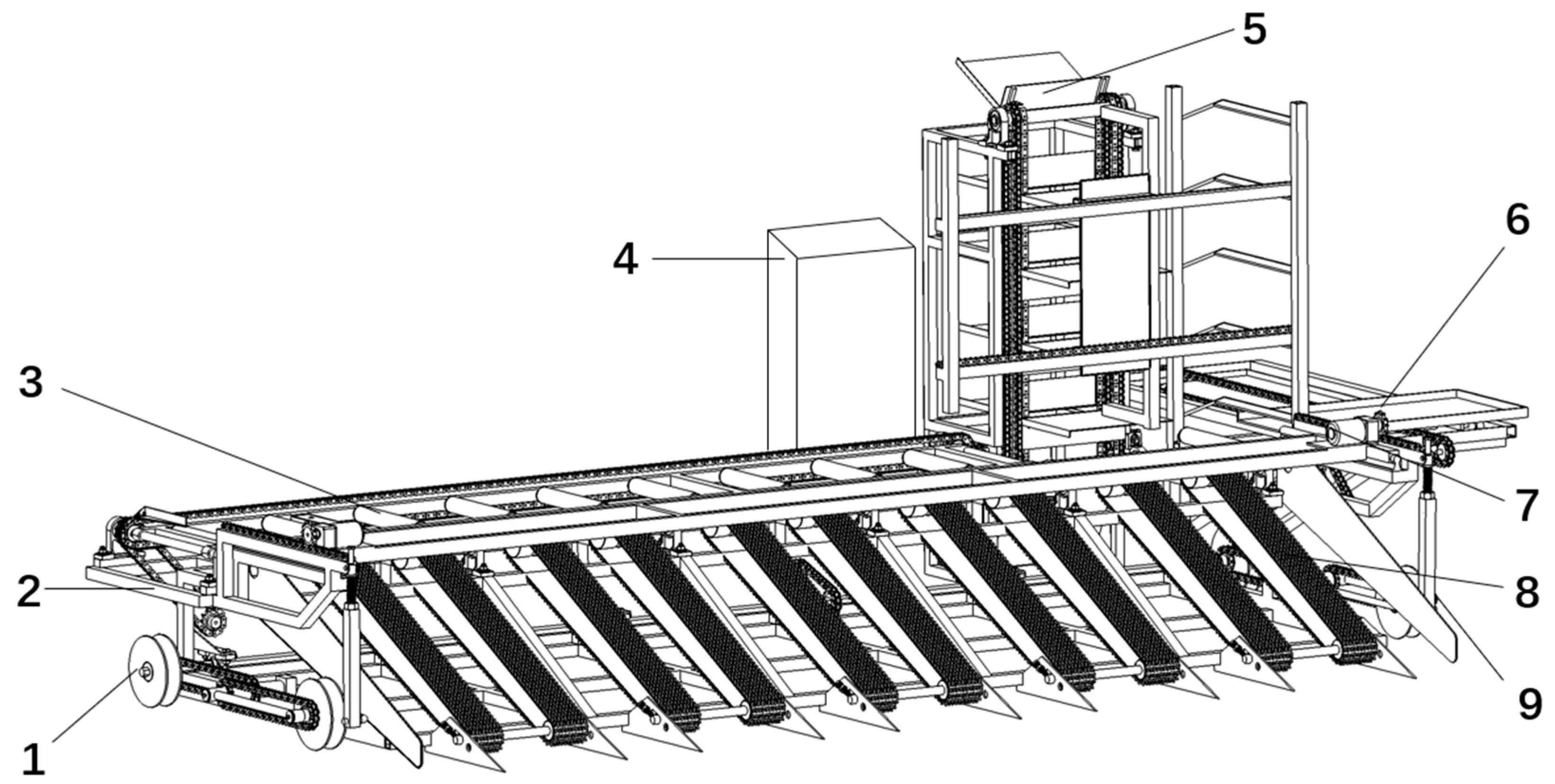
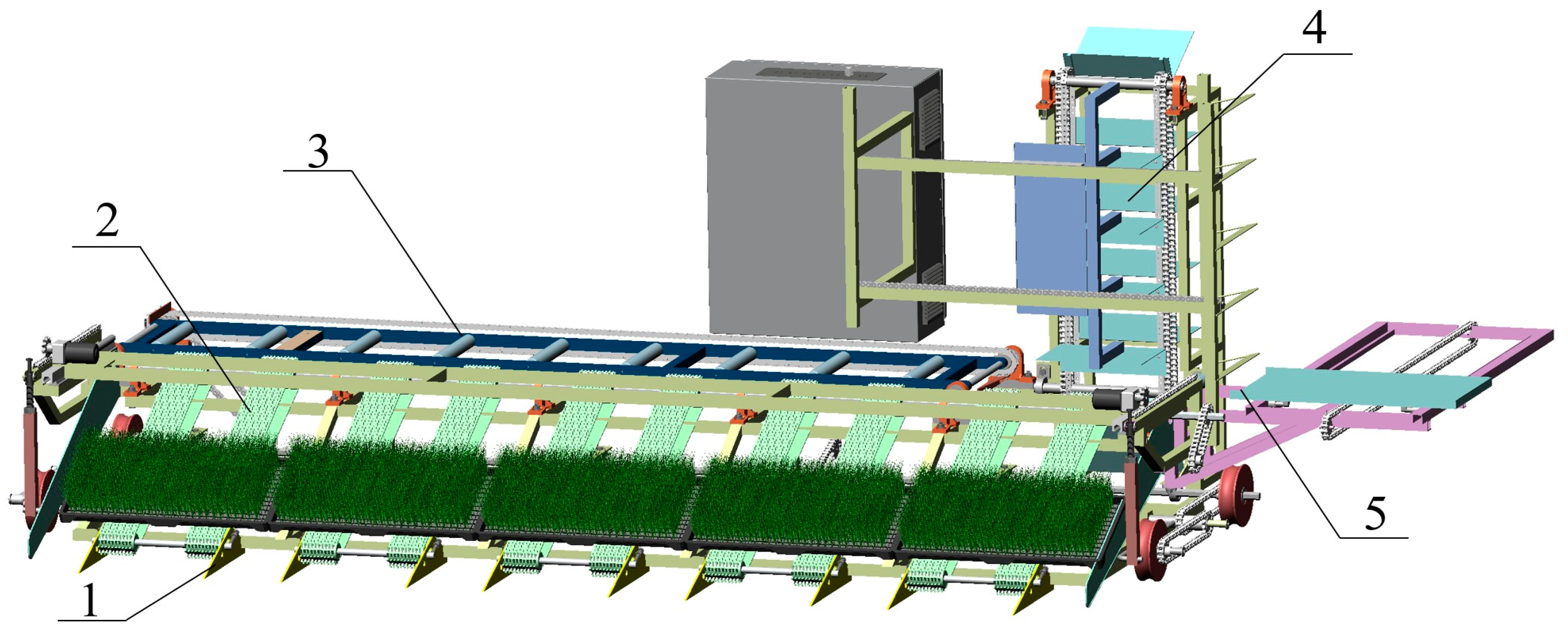
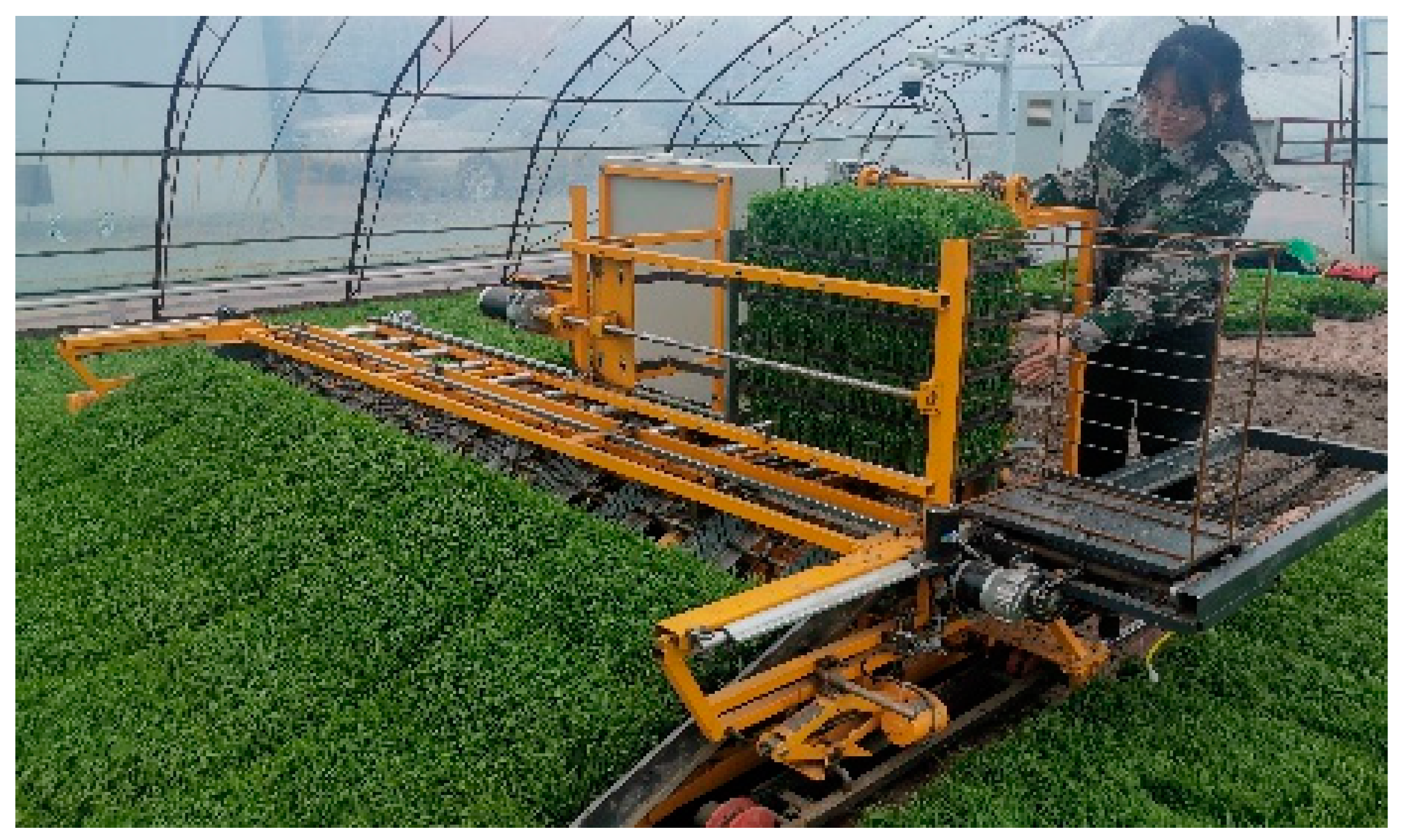
2.2. Overall Structure and Working Principle

The entire structure of the rice hard disk seedling raising fully automatic disc lifting machine includes a disc lifting shovel, a longitudinal conveyor belt, a circulation mechanism, and a control box. The conveying stage includes the longitudinal conveying belt conveying stage and the transverse conveying stage, and stacking and framing include a cyclic stacking mechanism and framing mechanism, as shown in Figure 2. The whole machine operates in the shed, which is not convenient for operation. However, our job is to shovel a standard 5-disk hard drive, and the structure of the whole machine needs to be able to withstand the basic requirements of operating in the shed. The relevant working parameters of the machine are shown in Table 1.
The operational mechanism of this machine may be described as follows: while in use, the power motor moves forward along a predetermined track via the walking wheel. Simultaneously, the lifting shovel is capable of being inserted from the underside of the seedling tray to accomplish the separation of soil. In the forward operation of the machine, the longitudinal conveyor belt facilitates the upward movement of the rice trays until the entire row of trays is conveyed to the horizontal conveyor device. The rice trays are systematically inserted into the circular stacking device through the proximity switch in the horizontal conveyor mechanism until the set of five rigid rice trays is fully assembled. This process accomplishes the initiation of automatic operation. The personnel makes real-time adjustments based on the operational situation using the touchscreen control panel. This is performed to ensure the uninterrupted and continuous functioning of the machine, to fulfill the demands of multi-line fully automated disc lifting operations and successfully carry out the entire disc lifting process. The operational procedure of the hoisting machine is depicted in Figure 3.

3. Key Component Design

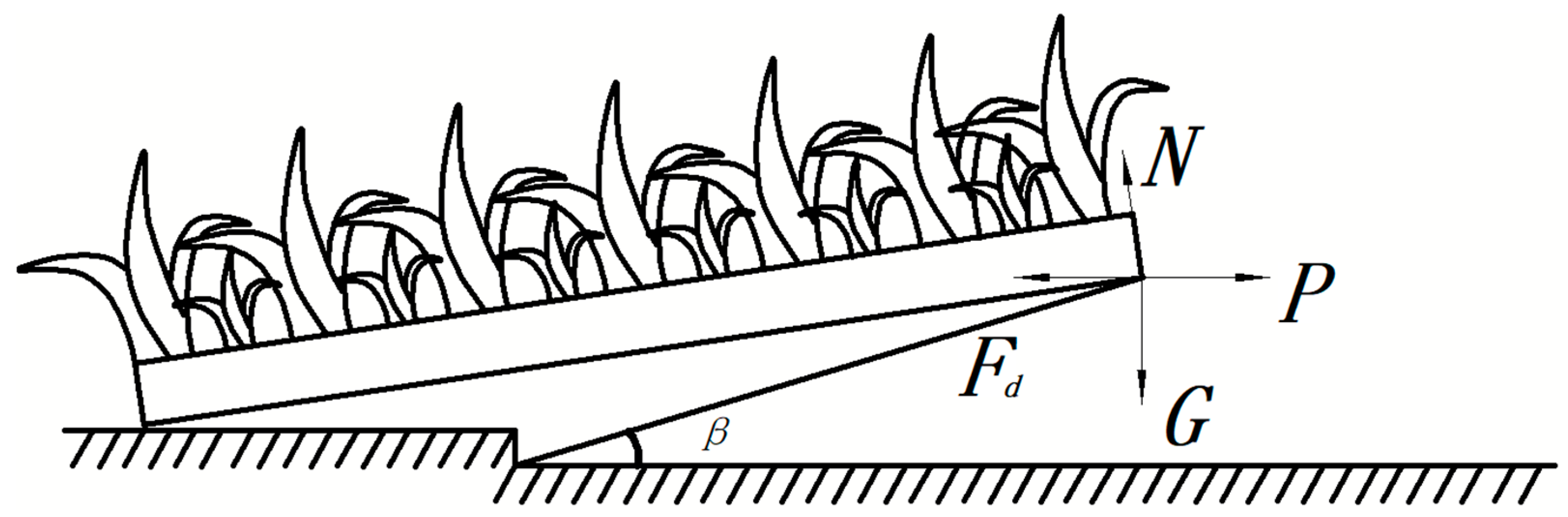
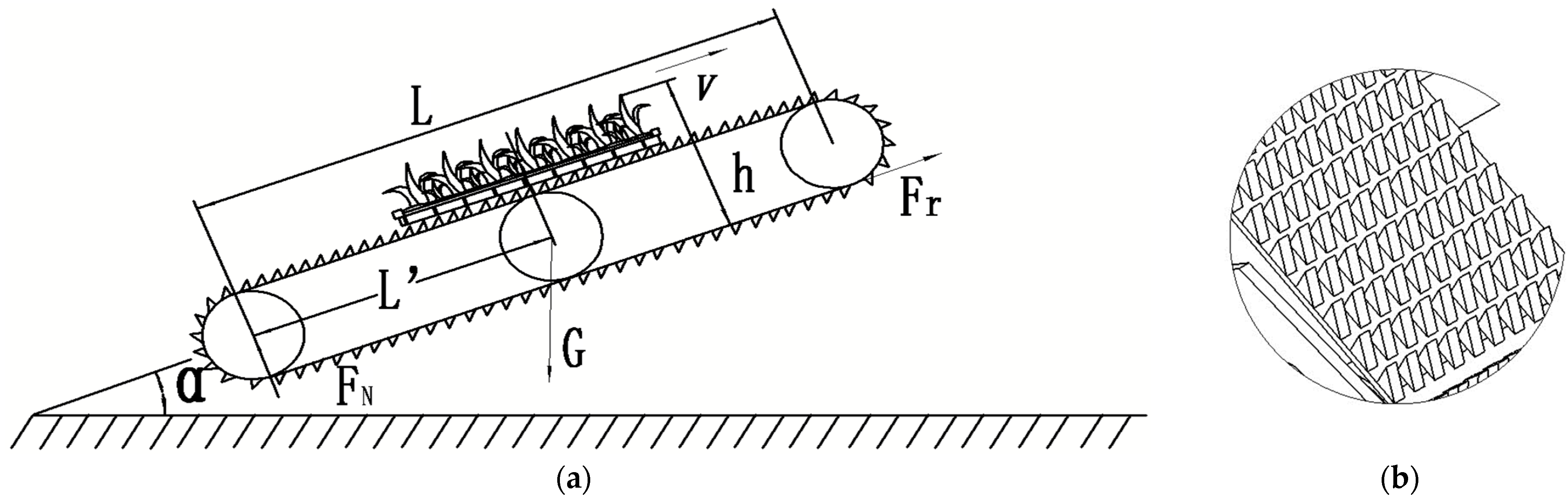
3.1. The Force and Mechanism Design of the Rice Seedling Tray during the Lifting Process

3.1.1. Design of Shovel Tip Shape

The primary purpose of the disc shovel is to effectively employ the substantial sliding cutting impact of its triangular tip to sever the dirt and afterward convey it to either side of the shovel. This process aims to minimize the resistance encountered by the shovel tip throughout its operation. The lifting shovel is positioned at the leading edge of the apparatus. Throughout the operational procedure, the shovel tip effectively detaches the resilient seedling tray from the soil bed and then conveys it rearward to the longitudinal conveying section. The lifting shovel can potentially cause soil leakage from the bottom of the rice tray during the lifting process. This can result in a reduction in the overall weight of the tray during lifting, hence facilitating its future transportation. Figure 4 depicts the structural diagram of the lifting shovel. According to the structure of the hard seedling tray, a 10 mm thick steel plate with a spacing of 230 mm is selected for the distance between the tray and the shovel to ensure smooth and reliable transportation of the tray to the next stage.

3.1.2. Design of Shovel Tip Inclination Angle

The inclination angle of the shovel tip is the angle between the shovel tip and the horizontal plane, and the inclination angle of the shovel tip has a significant impact on the soil penetration ability and forward resistance of the disc lifting machine. The force analysis of the seedling tray on the shovel tip is shown in Figure 5. In the figure, P represents the force required for the rice tray to move on the lifting shovel, which is provided by the horizontal component of the entire machine during the forward process. It is mainly used to overcome the support and friction forces in the horizontal direction.
According to the force diagram, the equation set is listed as
Pcos β F d G sin β 0
N G cos β P sin β = 0
where F d = f N ; P—the force required for the rice tray to move on the shovel tip, N; N—the support force of the shovel tip on the seedling tray, N; G—the gravity of the rice tray, N; Fd—the friction force of the rice seedling tray when moving on the shovel tip, N; and f—the friction coefficient between the seedling tray and the shovel tip.
The equation set is transformed into
P G tan β + f G 1 f tan β
The relationship between the force required for the rice seedling tray to move on the shovel tip and the inclination angle of the shovel tip, which is converted from Equation (3), indicates that the force required for the rice seedling tray to move on the shovel tip increases with the increase in the shovel tip angle. The range of shovel tip inclination angle is 0–24°.

3.2. Design of the Force and Mechanism of the Rice Tray during Longitudinal Transportation

The center of mass of the rice tray on the longitudinal conveyor belt is subjected to centrifugal force and the transverse force of gravity. At this time, there are two longitudinal conveyor belts at the bottom of each rice tray. Because the weight of each rice tray is about 7 kg, the stability of the rice tray on the longitudinal conveyor belt is crucial for the overall performance of the prototype. In the case when the longitudinal conveyor belt transports the rice tray to the transverse conveying stage (the status of the rice tray is shown in Figure 6, the mechanical equilibrium equation for the limit state of the rice seedling tray when transported on a longitudinal conveyor belt is established as follows:
F T = G sin α F N = G cos α G h sin α = G L cos α
where F T the tangential force N of the longitudinal conveyor belt on the seedling tray, N; G—the gravity of the rice tray, N; α—the maximum overturning angle of the rice seedling tray on the uphill slope, °; FN—the normal action N of the longitudinal conveyor belt on the seedling tray, N; h—the vertical height from the center of gravity of the rice tray to the longitudinal conveyor belt, m; L—the walking distance of the rice tray, m; and L—the distance from the center of gravity of the rice tray to the longitudinal conveyor belt, m.
The limit state of the upward slope of seedlings is the critical overturning state of the seedling tray during transportation in the longitudinal conveyor belt. In this case, the support force F N at the bottom of the seedling tray on the longitudinal conveyor belt is equal to the product of the center point of the limit state of the seedling tray and the corresponding force arm of the gravity of the seedling tray along the longitudinal conveyor belt direction and the vertical ground angle direction. It can be obtained that the limit angle of the longitudinal conveyor belt when the seedling tray is upward is
α = a r c tan L h
Through the above analysis, it can be seen that the stability and anti-overturning ability of the prototype are related to the height of the center of gravity. The lower the height of the center of gravity, the better the performance. When designing the longitudinal conveyor belt, weight distribution is fully considered to ensure that the height of the center of gravity of the seedling tray is low, which can ensure the stability requirements of the conveying operation process. By substituting each parameter value into Equation (5), the maximum overturning angle of the seedling tray on the slope is 59°.

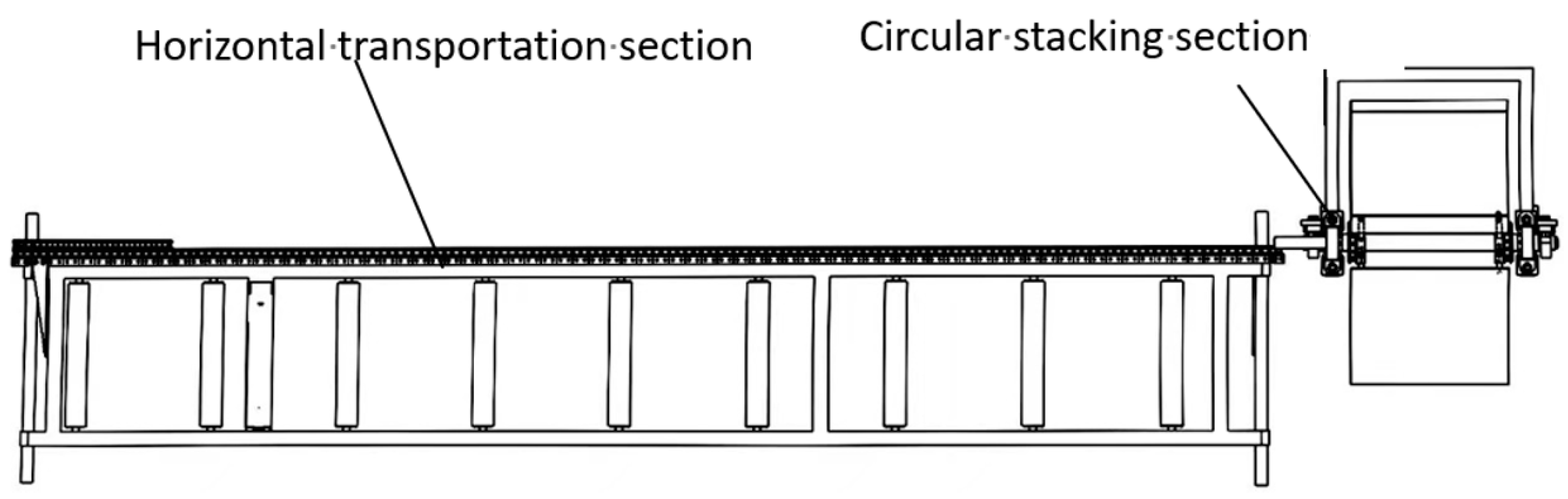
3.3. Design of Horizontal Mechanism

The last task involves pushing each of the five tray trays in the horizontal conveying section into the stacking work area one at a time and then pushing each tray’s horizontal push rod into the following step of stacking conveying. If the hard disk does not fall, the distance between the centers of the three adjacent drums should be greater than half of the length of the hard disk. The seedling hard drive studied is a common 600 mm × 300 mm × 30 mm polyvinyl chloride hard drive on the market and can be used as the design basis for drum conveyor modules. Given the diameter of the drum d = 40 mm, taking the center distance of the drum as 270 mm, the drum gap is obtained as 230 mm, and the selected material is a smooth drum with a stainless-steel surface. The horizontal conveying device is detailed in Figure 7.

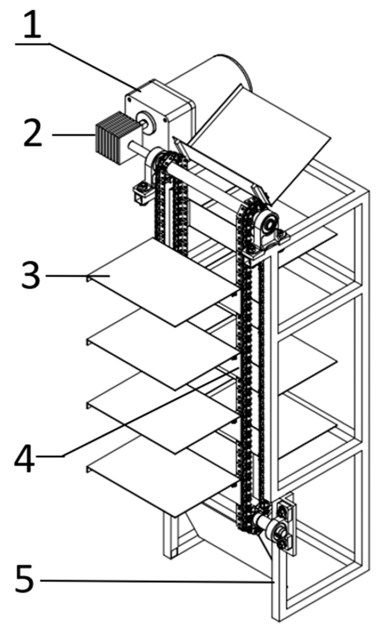
3.4. Stacked Disk Structure Design

The circular stacking device mostly determines the final framing. As seen in Figure 8, it is mainly made up of sprockets, chains, motors, and stacking devices and is dispersed across the right side of the entire machine. To accept the rice trays pushed to the device, a total of 10 stacked tray pallets are mounted on the chain. To regulate the position of the stacked tray and make sure that the rice trays drop into it easily, the chain rotates in a clockwise direction. The frame movement starts once all five sets in a row have been advanced, and the work procedure is complete at that point. The installation position of the bearing seat on the rack and the circulating stack tray bracket is determined, and the circulating stack tray module is designed through the graphic method. The tray spacing is determined as 188.5 mm, and the closest distance from the tray to the bottom is 100 mm. The material is made of wear-resistant and strong stressed steel.

Stacked Tray Conveying Model

There will be a period of time when the rice trays are horizontally transported to the stacking area as they are pushed one at a time to the stacking area. This is because pushing the toothed rollers during the horizontal conveying process takes time (from the beginning of the stacking mechanism’s circulation to the end of the five-tray releasing process). The integrity of the trays and seedlings can be compromised to some extent to maintain the duration interval between each tray. To achieve continuous stacking of rice trays, the speed of the rice tray must be rigorously controlled during the entire horizontal conveying operation [24]. The cycle of stacking disks starts to work until the end of the five disk assembly, as shown in Figure 9.The stacking speed of the circular stacking mechanism should be greater than the conveying speed of the horizontal conveying. Figure 8 shows the conveying model of the circular stacked tray conveying mechanism. Until the complete process of tray lifting is completed, the tray is transported horizontally at a uniform speed, and t0 is when the second tray completes stacking. In this case, the distance between the second tray and the third tray is
L 0 = v 1 t
where L0—the distance between the second and third rice trays at the L0-t0 moment, m; v1—the horizontal conveying section speed, m/s; and ∆t—the pushing time, s.
L 1 = L 0 v 0 v 1 z v 0
where L1—the distance between the third and fourth rice trays at time L1-t1, m; v0—the velocity of the stack conveyor section, m/s; and z—the distance between the third tray and the stacked tray to be horizontally transported, m.
The fourth tray, designated as t2, will be moved to the area where stacked trays are conveyed. The distance between the horizontal conveying section and the tray stacking region should be nearly zero to ensure continuous stacking of trays. The kinematic formula states that it must comply with the following conditions:
S z 2 S z v 0 + v 1 v 1 + L 1
where S is the length of the rice seedling tray, m.
The last rice tray finishes stacking at time t4, completing the cycle from t0 to t4. Equations (2)–(4) conclude that the stack conveyor section’s speed satisfies the following criteria:
v 0 v 1 2 t + v 1 S S v 1 t

4. Simulation of the Performance of the Lifting Machine

4.1. Simulation Analysis

The rice tray is hoisted by the lifting shovel and pushed to the longitudinal conveyor belt during the lifting stage by the locomotive’s progress. The process of the rice tray ascending onto the longitudinal conveyor belt as it prepares to enter the stacking area is known as the longitudinal conveyor stage. The movement of the rice tray during lifting and transportation was simulated using EDEM software. The influence of the structural parameters that need to be determined on the assessment indicators was examined based on the simulation’s findings to establish the ideal parameters.
The entire procedure was designed to last 14 s, and measurements were taken every 0.01 s to make it easier to observe how the soil was distributed inside the seedling tray and to calculate the pace at which seedlings were moving at different range intervals. Figure 10a depicts the static diagram of the simulation process device.
Given the corresponding beginning shovel angle, locomotive travel speed, and longitudinal conveyor belt conveying speed, Figure 10b depicts a static diagram at that precise point. As can be observed, when the device is starting up, the particles inside the disc tend to lean outward and toward the disk’s edge. The device’s stability greatly improves and the parameters may now be changed to efficiently control the direction in which the particles move inside the disc. Table 2 shows comprehensive information.
The CTM2050 universal testing machine was used to conduct shear tests on rice sprouts with a moisture content of 28.2%. For the shear test, the test was repeated 10 times, and the average of the results was taken as the shear modulus of the rice sprouts. When the moisture content was 28.2%, the shear modulus of rice sprouts was 83.36 MPa.
Poisson’s ratio refers to the absolute ratio of radial strain to axial normal strain of a material under single tension or compression, also known as the transverse deformation coefficient. It is the elastic constant that reflects the transverse deformation of the material. Using the definition method to measure the Poisson’s ratio of rice seedlings, the calculation formula is
μ = ε x ε y = L / L H / H
where μ —Poisson’s ratio; εx—radial strain of rice seedlings; εy—axial strain of rice seedlings; ∆L—absolute radial deformation of rice seedlings, mm; L—initial diameter of rice seedlings, mm; ∆H—absolute axial deformation of rice seedlings, mm; and H—initial length of rice seedlings, mm
The measurement of rice leaf parameters mainly focuses on the number of rice leaves, leaf height, and leaf area. In the process of making rice samples mentioned earlier, the number of leaves per rice plant was recorded and the arithmetic mean was taken, resulting in approximately three leaves per rice plant. During the measurement process, each leaf was measured three times and the average value was taken. The height of the rice seedling was between 10.5 cm and 16 cm, and the leaf area was between 6.3 square centimeters and 7.7 square centimeters.
The parameters shown in Table 2 were calculated using a universal testing machine and the average moisture content was measured through weighing.

4.2. Simulation Analysis

4.2.1. Test Factors

(1)
Angle of lifting shovel
Figure 10b shows a static diagram at that particular location given the corresponding initial shovel angle, locomotive travel speed, and longitudinal conveyor belt conveying speed. As can be seen, the particles inside the disc tend to lean outward and toward the disk’s edge when the gadget is first powered up. The device’s stability significantly increases, and it is now possible to adjust the parameters to effectively regulate how the particles flow inside the disc. The data in Table 1 are complete.
(2)
Longitudinal conveyor belt speed
Each hard seedling tray weighs an average of 7 kg, and the more weight there is, the more dependable the longitudinal conveyor belt transportation is. In general, the seedling tray transportation is smoother the slower the longitudinal conveyor speed is. On the other hand, the seedling tray is easily damaged or jammed. As a result, the experiment was carried out at speeds of 0.04 m/s, 0.08 m/s, 0.14 m/s, 0.2 m/s, and 0.24 m/s for the longitudinal conveyor belt.

4.2.2. Test Indicators

(1)
Seedling tray integrity rate C
The regular lifting and delivery of rice trays up until the point when they reach the rice tray frame and the entire lifting process is successfully completed is referred to as the completion rate of rice trays. The formula for determining the rice trays’ completion rate is
C = C 1 C 2 × 100 %
where C is the completeness of the rice tray, %; C1 is the number of qualified starting plates, pieces; and C2 represents the total number of starting orders, units.
(2)
Starting efficiency η
Currently, 300–400 discs per hour can be manually lifted while producing rice hard discs. It can significantly lower the amount of labor required and increase productivity if it has a completely automatic lifting function for the nurturing of rice hard disc seedlings. The calculation of lifting efficiency is as follows:
η = Z 1 t
where η is the efficiency of the starting disk, pieces; Z1 is the number of successfully started disks, pieces; and t is the working time, h.
(3)
Chuck rate σ
The term “chuck rate” describes a scenario in which rice trays are squeezed while still hoisted normally, without impairing the operation. The amount of clay that is attached to the trays varies due to the complicated working environment in the shed, and the moisture and weight of the seedlings inside the trays are too great, causing compression between the trays, but this does not affect the lifting process in its entirety or harm the rice trays. The chuck rate calculation formula is
σ = σ 1 Z × 100 %
where σ is the chuck rate, %; σ1 refers to the number of hard drives that may experience a jam but do not affect the complete operation; and Z represents the total number of rice trays participating in the experiment.

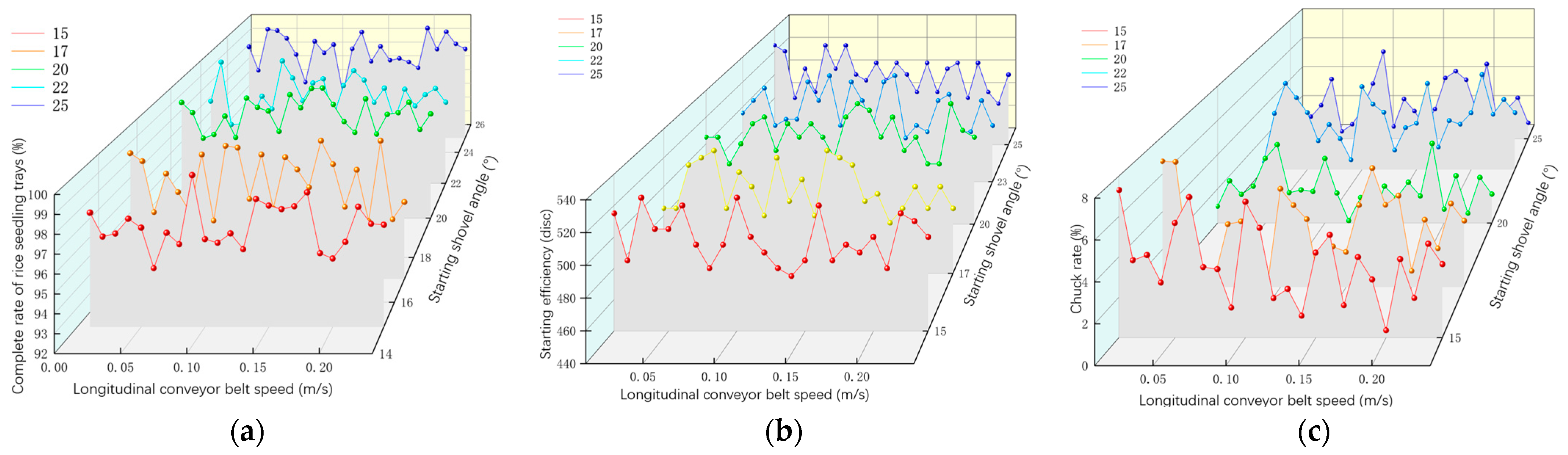
4.2.3. Testing Results and Analysis

According to the illustration above, as the rice tray is lifted, it will come into contact with the tray shovel, the conveyor belt, and the interactions between the trays, which will result in the particles turning over and bursting out. With the conveyor belt conveying speed too high and the tray shovel’s angle fluctuating, which makes the particles in the tray more unstable, the probability of this phenomenon occurring randomly will increase. Table 3 displays the simulation test results for various conveyor belt speeds under various starting shovel angles.
Selecting the angle of the starting disc shovel, the speed of the longitudinal conveyor belt, and the forward speed of the locomotive as the test factors, in order to obtain the optimal parameters of the three factors, the code table of the test factors is shown in Table 4.
(1)
Curve of Figure 11a: The five varied lifting shovel angles cause the overall integrity rate of the seedling tray to show a trend of initially increasing and then decreasing when the longitudinal conveyor belt speed increases. The quickest rising and falling speeds are at 25 degrees and 17 degrees, respectively, for the lifting shovel angle. The subsequent phases are level, with the seedling tray’s integrity rate being maximum at a lifting shovel angle of 20 degrees.
(2)
The starting efficiency from 15° to 17° exhibits a stable increase at first with the continuous increase in longitudinal conveyor belt speed, followed by a significant increase at 20°; subsequently, it gradually decreases with a small fluctuation in the middle of the curve, but the overall increase is not significant and the change is relatively stable, with the highest starting efficiency at 20°.
(3)
The five distinct lifting shovel angles cause the total chuck rate to show a tendency of first increasing and then decreasing as the longitudinal conveyor belt speed continues rising in the curve of Figure 11c. The fastest lifting and lowering speeds are achieved when the lifting shovel angle is 15 and 22 degrees, respectively. The other stages are flat, with the chuck rate being the lowest and the lifting shovel angle being 22 degrees.

5. Starting Performance Test

5.1. Multifactor Experimental Indicators and Factors

The Qixing Farm of the Sanjiang Management Bureau was chosen for the experiment, and a hard seedling tray was employed to test the effectiveness of the fully automatic rice hard disc seedling rearing system. The experimental site is depicted in Figure 12.

5.2. Test Result

The experiment was divided into 23 groups, with each group repeated three times. Each group collected a total of 500 pallets for data statistics, and took the average of three times for each group. Record tray efficiency, tray integrity rate, and tray blockage rate based on the angle of starting the disc shovel, the speed of the longitudinal conveyor belt, and the forward speed of the locomotive as test factors. Table 5 shows the test results.

5.3. Regression Model Establishment and Analysis of Variance

To evaluate the impacts of shovel angle, locomotive travel speed, and longitudinal conveyor belt speed on the completeness, efficiency, and jamming rate of rice trays during the lifting process, Design-Expert11.0 software was used to create a response surface regression model. Table 6 presents the variance analysis of the experimental results [25].
The Design Expert11.0 software was used to perform regression analysis on experimental data, which was then followed by factor analysis of variance. The regression equation between performance indicators and factor coding values was discovered after significant influencing factors had been eliminated [26].
(1)
Establishment of regression models between the completeness rate of rice seedling trays and various factors.
The p-value of the regression model for the completion rate of rice trays is less than 0.01, which indicates that the model’s significance is very significant, according to the table of analysis of variance. They all have p-values greater than 0.05, including the interaction terms X1X3 between the starting disc shovel’s angle and the longitudinal conveyor belt’s speed and X2X3 between the locomotive’s travel speed and the longitudinal conveyor belt’s speed. The interaction effect does not significantly impact the rice tray’s completion rate. After removing them, the resulting derived regression equation is displayed below.
Y1 = −5482X12 − 1.61X22 − 0.9017X32 − 0.5X1X2 + 0.5392X1 − 0.5392X2 + 0.4393X3 + 99.56
(2)
Establishment of regression models for starting efficiency and various factors.
The p-value of the regression model for starting efficiency is less than 0.01, which indicates that the model’s significance is extremely significant, according to the table of analysis of variance. The interaction terms X1X2 between the angle of the disc lifting shovel and the longitudinal conveyor belt speed, X2X3 between the locomotive travel speed and the longitudinal conveyor belt speed, and X1X3 between the angle of the disc lifting shovel and the longitudinal conveyor belt speed all have p-values that are greater than 0.05 among them. The regression equation that was derived after subtracting the interaction effect from the disc lifting efficiency is displayed as follows:
Y2 = − 22.91X12 − 16.73X22 − 19.38X32 + 6.49X1 + 4.91X2 + 5.52X3 + 526.78
(3)
Establishment of regression models between chuck rate and various factors.
According to the table of analysis of variance, the regression model p value of the chuck rate is <0.01, suggesting that the model significance is extremely significant. Among these, the p-values of the interaction term X1X2 between the angle of the starting disc shovel and the speed of the longitudinal conveyor belt, as well as the interaction term X2X3 between the locomotive moving speed and the speed of the longitudinal conveyor belt, are all > 0.05. The interaction effect on the initial disc efficiency is insignificant, and the regression equation derived after removing it is presented in the following equation.
Y3 = 0.2169X12 + 0.1639X22 + 0.2346X32 − 0.0625X1X3 − 0.0612X1 + 0.0489X2 + 0.0882X3 + 526.78

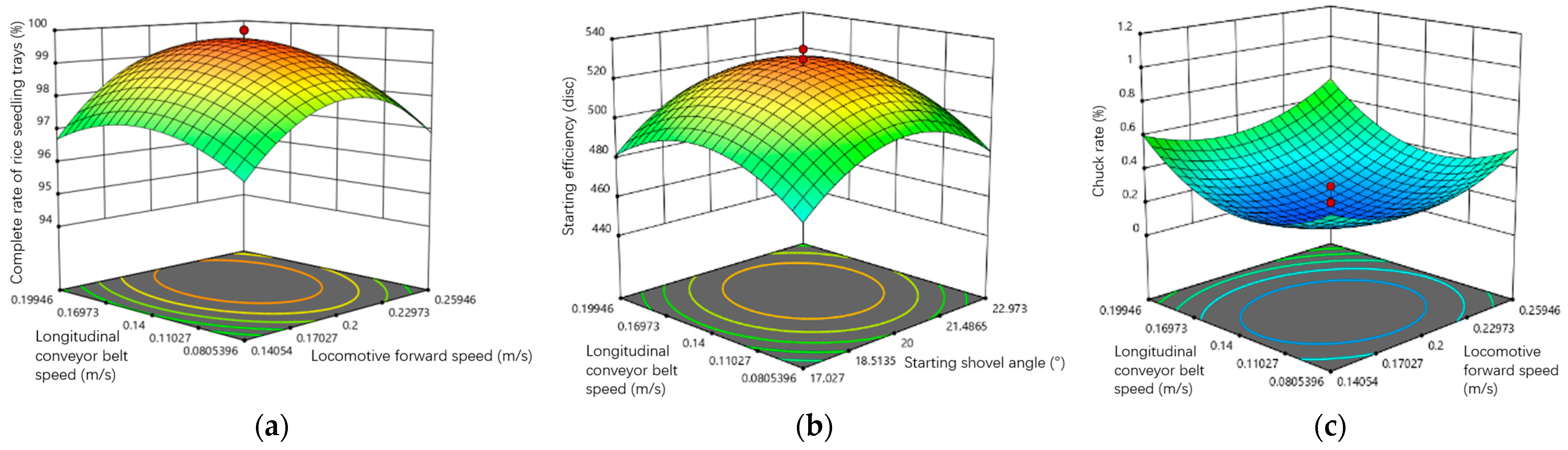
5.4. Multifactor Interactive Response Surface Analysis

Design Expert11.0 software was used to analyze the response surface impacted by interacting factors to intuitively analyze the link between experimental indicators and various parameters, as illustrated in Figure 13.
The relationship between locomotive travel speed and track speed has the largest influence on how complete the rice tray is, according to response surface research. Figure 13a demonstrates that the integrity rate of the rice tray exhibits a curve that increases initially before decreasing as the longitudinal conveyor belt speed increases. The integrity rate of the rice tray exhibits a curve with an initial increase and a subsequent decrease with an increase in locomotive advance speed at the same longitudinal conveyor belt speed. The rice tray’s completion rate is highest when the locomotive travels at 0.2 m/s and the longitudinal conveyor belt travels at 0.14 m/s.
The interaction between the lifting shovel and the track speed has the largest influence on the lifting efficiency, according to the response surface study. The disc efficiency under the same disc angle exhibits a curve that first increases and then decreases with an increase in longitudinal conveyor belt speed, as shown in Figure 13b, while the lifting efficiency exhibits a curve that initially increases and then decreases with an increase in lifting shovel angle. The highest disc lifting efficiency occurs when the shovel’s angle is 20 degrees and the longitudinal conveyor belt speed is 0.14 m/s.
The interplay between locomotive travel speed and track speed has the largest influence on lifting efficiency, according to the response surface study. According to Figure 13c, the lifting efficiency exhibits a curve that initially decreases and then increases with an increase in longitudinal conveyor belt speed. Similarly, the lifting efficiency exhibits a curve that initially decreases and then increases with an increase in locomotive forward speed. The lowest chuck rate occurs when the locomotive moves forward at 0.2 m/s and the longitudinal conveyor belt moves at 0.14 m/s.

5.5. Multifactor Interactive Response Surface Analysis

The influence of numerous experimental variables on various experimental indicators as well as the interaction effect of three components on various performance indicators were discovered through multi-factor experimental research. Using Design Expert 11.0 software, the completion rate, beginning efficiency, and jamming rate of rice trays were optimized and solved. A nonlinear mathematical model was created, and the optimization conditions were designed to reduce the completion rate, beginning efficiency, and jamming rate of rice trays. The restriction requirements were
m i n Y = f X 1 , X 2 ,   X 3 s . t .   X 1 15   ,   25 X 2 0.1   ,   0.4 X 3 0.04   ,   0.24
The central composite response surface design (CCD) of Design Expert 11.0 was used for parameter optimization to find the best starting effect and ideal mix of experimental parameters. Based on the maximization of the integrity rate of the rice tray, the optimization results are as follows: the highest integrity rate of the rice tray, at 99.48%, is achieved when the starting shovel angle is 21.278°, the locomotive traveling speed is 0.333 m/s, and the longitudinal conveyor belt conveying speed is 0.17 m/s. The starting efficiency is 510 trays/h and the chuck rate is 0.4%. The initial effect is the finest in this case.
The completion rate of the rice seedling tray is 99.26%, the tray lifting efficiency is 510 trays, and the tray clamping rate is 0.4%. These optimization findings were confirmed through trials. This basically supports the optimization results, showing that they can be applied to enhance the tray lifting effectiveness of the rice hard disc seedling automatic tray lifting machine and achieve the optimum tray lifting effect.

6. Discussion

(1)
The angle of the tray-lifting shovel somewhat influences the three indications. This is because the rice tray is more likely to be secondarily displaced (especially when placed in the shed, where there is a gap between the trays), which in turn affects the tray lifting effect—the larger the angle of the tray lifting shovel, the greater the impact on the rice tray. However, it was discovered during actual production testing that very few rice trays might jam into one another as a result of some old rice trays being deformed. However, because of the lifting shovel’s impact, it can actually stop rice trays from colliding with one another. Table 3 shows that the disc-lifting effect is improved when the disc-lifting shovel is angled between 20 and 22 degrees.
(2)
Because the rice seedling tray has flange widths on both sides, the longitudinal conveyor belt has the greatest influence on the three indicators. On the longitudinal conveyor belt, there are occasionally stacking situations because of its placement function. The best results are therefore obtained while carrying the rice seedling tray at a longitudinal conveyor belt transportation speed between 0.14 m/s and 0.2 m/s, according to data analysis and subsequent real production verification.
(3)
The three indications are significantly impacted by locomotive speed, and since the environment inside the shed is complicated, it can be altered in accordance with the demands of the job being performed.
The rice tray integrity rate is highest at 99.48%, the starting efficiency is 510 trays/h, and the chuck rate is 0.4% when the starting shovel angle is 21.278°, the locomotive traveling speed is 0.333 m/s, and the longitudinal conveyor belt conveying speed is 0.17 m/s.

7. Conclusions

(1)
In order to raise hard rice seedlings in northern greenhouses, fully automatic self-propelled tray lifting equipment was designed. Important parts were designed, including the tray lifting structure, the conveying mechanism, the stacking mechanism, and the control system.
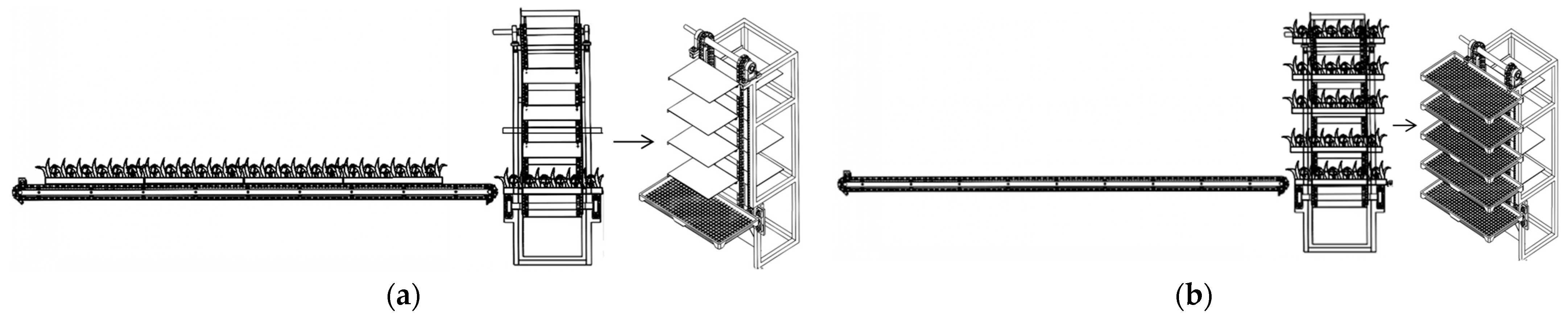
(2)
The procedure of the rice tray from the longitudinal conveying section and the transverse conveying section to the stacking stage was examined using a mechanical model of the conveying mechanism. The flawless transverse transportation of the rice tray via the two steps to the stacking stage was determined.
(3)
The angle of the disc-lifting shovel, the speed of the locomotive, and the speed of the longitudinal conveyor belt were used as experimental factors, and the completeness rate, disc-lifting efficiency, and chuck rate were used as experimental indicators, in an orthogonal rotation experiment. Analysis revealed that each of the three factors significantly affects the experimental indicators.
(4)
Based on an analysis of the experimental results’ actual production processes, the ideal parameter setting was identified: the rice seedling tray completeness rate is highest at 99.48%, the disc lifting efficiency is highest at 510 discs/h, and the chuck rate is lowest when the angle of the disc lifting shovel is 21.278°, the locomotive traveling speed is 0.333 m/s, and the longitudinal conveyor belt conveying speed is 0.17 m/s. The experimental indicators are capable of lifting hard rice seedling trays using a disc.

Author Contributions

Conceptualization, G.Z. and S.Y.; data curation, G.Z., Y.L., P.W. and L.L; formal analysis, G.Z., B.L. and L.L.; funding acquisition, P.W. and B.L.; investigation, G.Z. and S.Y.; methodology, G.Z. and S.Y.; project administration, Y.L. and B.L.; resources, S.Y. and Y.L.; software, G.Z.; supervision, S.Y. and Y.L.; validation, G.Z., S.Y., L.L. and P.W.; visualization, G.Z., P.W., B.L. and L.L.; writing—original draft, G.Z. and S.Y.; writing—review and editing, G.Z. and B.L. All authors have read and agreed to the published version of the manuscript.

Funding

This study was funded by the Heilongjiang Provincial Research Center for Rice Ecological Seedling Raising Equipment and Full Mechanization Engineering Technology. Special project of central guidance for local science and technology development, approval number: SBZY2020E063.

Institutional Review Board Statement

Not applicable.

Data Availability Statement

All data are presented in this article in the form of figures and tables.

Conflicts of Interest

The authors declare no conflict of interest.

References

  1. Ying, L. Application of Stacked Disk Darkroom Seedling Breeding Technology. North. Rice 2021, 6, 42–43. [Google Scholar] [CrossRef]
  2. Li, J.; Wu, R.; Wang, H. The Technology of Rice Seedling Cultivation with Constant Temperature Stacking and Darkness and Its Promotion and Application. Mod. Agric. Mach. 2016, 2, 50–51. [Google Scholar]
  3. Wu, X.; Li, C.; Zou, Z.; Liu, X.; Han, G.; Zhai, S.; Liu, C. Analysis on the Technology of Rice Seedling Cultivation in a Dark Room with Constant Temperature Stacking Tray. Agric. Sci. Technol. Commun. 2020, 12, 252–253. [Google Scholar]
  4. Kong, L. Preliminary sudy on the technique of rice seedling cultivation in a dark room with constant temperature stacking tray. Agric. Sci. Technol. Commun. 2019, 11, 217–218. [Google Scholar]
  5. Yan, D.; Wang, L. Research on the effect of super early rice seedling breeding technology on Yield in qixing farm. North. Rice 2018, 48, 12–17. [Google Scholar] [CrossRef]
  6. Li, Z.; Ma, X.; Li, X.; Chen, L.; Li, H.; Yuan, Z. Research progress in mechanized rice planting technology. J. Agric. Mach. 2018, 5, 1–20. [Google Scholar]
  7. Luo, X.; Wang, Z.; Zeng, S.; Zang, Y.; Yang, W.; Zhang, M. Research progress in mechanized direct seeding technology for rice. J. South China Agric. Univ. 2019, 5, 1–13. [Google Scholar]
  8. Ma, X.; Tan, Y.; Qi, L.; Huang, G.; Lu, F.; Chen, L. Design and testing of pneumatic automatic disc feeding device for rice seedling tray and seeder. J. Agric. Eng. 2016, 22, 63–69. [Google Scholar]
  9. Visser, M.-L.B. Tray Destacker and Pot Dispenser [EB/OL]. Available online: http://www.visser.eu/products/all-products/MHD-LB/ (accessed on 23 February 2016).
  10. Gu, S.; Yang, Y.; Zhang, Y.; Qiao, X. Development status of vegetable seedling production equipment system in the Netherlands and Its Enlightenment to China. J. Agric. Eng. 2013, 14, 185–194. [Google Scholar]
  11. Qi, F.; Zhou, X.; Zhang, Y.; Li, Z. The development of modern greenhouse equipment and technology in the world and Its Enlightenment to China. J. Agric. Eng. 2008, 10, 279–285. [Google Scholar]
  12. Kubota Industrial Co., Ltd. Seedling Box Supply Device. Japanese Patent 62-87008, 21 April 1987. [Google Scholar]
  13. Jing, G.; Agricultural Machinery Co., Ltd. Automatic Supply Device for Seedling Box for Seeders. Japanese Patent Showa 60-199304, 8 October 1985. [Google Scholar]
  14. Yi Agricultural Machinery Co., Ltd. Seedling Box Supply Device. Japanese Patent Showa 61-166306, 28 July 1986. [Google Scholar]
  15. Suzuki Forging Co., Ltd. Seeding Device and Seedling Box Supply Device. Japanese Patent Showa 61-58507, 25 March 1986. [Google Scholar]
  16. Qiwen Co., Ltd. Production Office Automatic Supply Device for Seedling Box. Japanese Patent Showa 62-205708, 10 September 1987. [Google Scholar]
  17. Kubota. Automatic Supply Device for Seedling Box [EB/OL]. Available online: http://www.jnouki.kubota.co.jp/sisetu/ikubyou/autobox/index.html (accessed on 27 December 2015).
  18. Iseki Rice Planting Equipment [EB/OL]. Available online: http://www.iseki.co.jp/products/nougyou/noug-02/#rice (accessed on 27 December 2015).
  19. Yanmar. Fully Automatic Seedling Box Automatic Supply Device for Rice Seedling Facilities [EB/OL]. Available online: https://www.yanmar.com/jp/agri/implement/agri_implement/flooded_rice/feature01.html (accessed on 27 December 2015).
  20. Yi, S. Rice Seedling and Seeder [EB/OL]. Available online: http://www.santah.com.tw/index.asp (accessed on 27 December 2015).
  21. Qiu, D. Automatic Feeding Box Setter: Taiwan. China Patent 85214362, 17 September 1996. [Google Scholar]
  22. Nanjing Agricultural Mechanization Research Institute, Ministry of Agriculture. Automatic Disc Feeder. Chinese Patent ZL98227269.3, 4 August 1999. [Google Scholar]
  23. Wang, Y.; Cao, L.; Wang, J. An Automatic Feeding Device for Rice Seedling Cultivation and Sowing Trays. Chinese Patent CN201210172, 2016. [Google Scholar]
  24. Wang, J.; Tang, H.; Wang, J.; Shen, H.; Feng, X.; Huang, H. Analysis and Experiment on the Mechanism of Seed Delivery and Transport of Finger Clip Type Corn Precision Metering Device. J. Agric. Mach. 2017, 1, 29–37+46. [Google Scholar]
  25. Gou, Y.; Li, H.; Wang, D.; He, H. Design and simulation optimization of small variable fertilizer spreaders based on EDEM. Res. Agric. Mech. 2022, 11, 65–71+76. [Google Scholar] [CrossRef]
  26. Xie, D.; Zhang, C.; Wu, X.; Wang, W.; Liu, L.; Chen, L. Design and testing of an air suction garlic seeder assisted by disturbing seed teeth. J. Agric. Mach. 2022, 2, 47–57. [Google Scholar]
Figure 1. Structure of hard seedling plate. (1) Edge protection. (2) Reinforcement ribs. (3) Plate bottom. (4) Flanging. (a) is the main view of the hard disk, (b) is the top view of the hard disk.
Agriculture 13 01929 g001
Figure 2. Fully automatic disc lifting machine for rice hard disk seedling cultivation. (1) Walking mechanism. (2) Rack. (3) Horizontal conveying roller. (4) PLC control system. (5) Circular stacking mechanism. (6) Collecting tray. (7) Pushrod. (8) Longitudinal conveying mechanism. (9) Height adjustment mechanism.
Agriculture 13 01929 g002
Figure 3. Working process of the lifting machine. (1) Starting stage. (2) Vertical transportation stage. (3) Horizontal transportation stage. (4) Circular stacking stage. (5) Gathering stage.
Agriculture 13 01929 g003
Figure 4. Structural diagram of lifting shovel. (1) Shovel. (2) Transmission shaft. (3) Frame. (4) Bolts and nuts.
Agriculture 13 01929 g004
Figure 5. Force diagram of the hard seedling tray.
Agriculture 13 01929 g005
Figure 6. (a) Status of rice seedling tray uphill; (b) is a detailed diagram of the track shape.
Agriculture 13 01929 g006
Figure 7. Structure diagram of horizontal conveying mechanism.
Agriculture 13 01929 g007
Figure 8. Schematic diagram of circular stacking mechanism. (1) Motor. (2) Revolution converter. (3) Stacking plate. (4) Chain. (5) Fixed holder.
Agriculture 13 01929 g008
Figure 9. Schematic diagram of rice tray stacking and conveying. The lateral conveying status of the rice tray at time (a); Horizontal conveying status of rice tray at time (b).
Agriculture 13 01929 g009
Figure 10. Simulation test process. (a) is a schematic diagram of seedling simulation, and (b) is a complete machine simulation operation diagram.
Agriculture 13 01929 g010
Figure 11. Simulation test curve of different conveyor belt speeds under different starting and shovel angles. (a): What is the completeness rate of the rice seedling tray at different angles of the lifting shovel under different longitudinal conveying speeds; (b): How the starting efficiency changes under different conditions of the two; (c): What is the chuck rate under different conditions for the two.
Agriculture 13 01929 g011
Figure 12. Experimental site of a fully automatic disc lifting machine for rice hard disk seedling cultivation.
Agriculture 13 01929 g012
Figure 13. Response surface of experimental factors on indicators. (a): The influence of locomotive forward speed and longitudinal conveying speed on the completeness of rice trays; (b): The angle of the starting disc shovel and the longitudinal conveying speed; (c): The Influence of Forward Speed and Longitudinal Transportation of Locomotive C on Chuck Rate.
Agriculture 13 01929 g013
Table 1. Operating parameters of the entire machine.
Serial NumberProjectUnitDesign Value
1Specification and model/Fully automatic disc lifting machine for rice hard disk seedling cultivation
2Structural style/Fully automatic
3Supporting power type/24 V lead acid battery
4Installed capacitykw2.8
5Overall dimensions (length × width × height)mm3900 × 2200 × 1260
6Overall weightKg800
7Number of work linesRow5
8Working speedm/h20–30
9Job widthmm3000
10Work efficiencyRice seedling tray/h400–500
11Traveling mechanism type/Guide rail ground wheel type
12Traveling mechanism ground wheel diametermmΦ120
Table 2. Material parameters.
Material TypeParameterNumerical Value
Seedling raising hard drivePoisson ratio0.319
shear modulus (Pa)1.5 × 10⁹
density (kg/m3)1850
SoilPoisson ratio0.30
shear modulus (Pa)1 × 10⁸
density (kg/m3)7865
Lifting shovelPoisson ratio0.30
shear modulus (Pa)7.9 × 10¹⁰
Rice seedlings—Recovery coefficient of rice seedlings0.681
Recovery coefficient of rice seedlings and soil0.21
Kinetic friction0.01~0.016
Static friction0.03~0.35
Table 3. Analysis table of test results.
Longitudinal Conveyor Belt Speed/Lifting Shovel Angle 1517202225
0.04 m/sSeedling tray integrity rate/%9395979694
Starting efficiency/disc420445465455430
Chuck rate/%1.21.10.811.2
0.08 m/sSeedling tray integrity rate/%9496989795
Starting efficiency/disc435460470465445
Chuck rate/%0.90.90.70.80.8
0.14 m/sSeedling tray integrity rate/%96981009997
Starting efficiency/disc475500530515485
Chuck rate/%0.60.40.10.20.5
0.2 m/sSeedling tray integrity rate/%9597999896
Starting efficiency/disc460490510500470
Chuck rate/%0.70.60.60.50.6
0.24 m/sSeedling tray integrity rate/%9294969593
Starting efficiency/disc455475495490460
Chuck rate/%1.41.20.91.11.3
Table 4. Experimental factors and coding.
CodeStarting Shovel Angle X1/(°)Locomotive Forward Speed X2 (m/s)Longitudinal Conveyor Belt Speed X3/(m/s)
+1.682250.40.24
+122.973 (23)0.25946 (0.26)0.199 (0.2)
0200.20.14
−117.027 (17)0.14054 (0.14)0.08
−1.682150.10.04
Table 5. Experimental arrangement and results.
CodeX1X2/ m/sX3/ m/sSeedling Tray Integrity Rate/%Starting Efficiency/DiscChuck Rate/%
117.0270.140540.0805954500.7
222.9730.140540.0805964650.6
317.0270.259460.0805964650.7
422.9730.259460.0805964700.8
517.0270.140540.19946954600.9
622.9730.140540.19946954750.7
717.0270.259460.19946984601.1
822.9730.259460.19946984800.8
9150.20.14974550.9
10250.20.14994750.7
11200.10.14944700.6
12200.30.14964950.7
13200.20.04974600.7
14200.20.24974901
15200.20.14995300.3
16200.20.141005250.2
17200.20.14995250.2
18200.20.14995350.1
19200.20.141005250.1
20200.20.141005300.1
21200.20.141005250.3
22200.20.141005250.1
23200.20.14995200.2
Table 6. Analysis of variance of regression model.
Evaluating IndicatorVariance
Source
Sum of SquaresFreedomMean SquareF ValueF ValueSignificance
Y1model71.7997.9822.32<0.0001**
X13.9713.9711.110.0054**
X23.9713.9711.110.0054**
X32.6412.647.380.0176**
X1 × 22.0012.005.600.0342*
X1X30.510.51.400.2581-
X2X30.510.51.400.2581-
X124.7814.7813.360.0029*
X2241.13141.13115.09<0.0001**
X3212.92112.9236.15<0.0001**
residual4.65130.3574---
lack of fit2.4250.48471.740.2305-
error2.2280.2778---
sum76.4322----
Y2model19,885.0192209.4564.48<0.0001**
X1575.271575.2716.790.0013**
X2329.141329.149.610.0085**
X3416.881416.8812.170.0040**
X1X23.1313.130.09120.7674-
X1X328.13128.130.82080.3814-
X2X328.12128.120.82080.3814-
X128342.218342.2243.47<0.0001**
X224445.2414445.24129.74<0.0001**
X325966.415966.4174.13<0.0001**
residual445.431334.26---
lack of fit295.43559.093.150.0726-
error150.00818.75---
sum20,330.4322----
Y3model2.2590.249545.61<0.0001**
X10.051210.05129.360.0091**
X20.032710.03275.980.0295*
X30.106210.106219.420.0007**
X1X20.001210.00120.22850.6406-
X1X30.031210.03125.710.0327*
X2X30.001210.00120.22850.6406-
X120.747510.7475136.66<0.0001**
X220.426710.426778.00<0.0001**
X320.874410.8744159.84<0.0001**
residual0.0711130.0055---
lack of fit0.015650.00310.44800.8041-
error0.055680.0069---
sum2.3222----
Note: p ≤ 0.01 indicates highly significant (**); 0.01 ≤ p ≤ 0.05 indicates significant (*); p > 0.05 indicates insignificant. - indicates that there is no data present.
Disclaimer/Publisher’s Note: The statements, opinions and data contained in all publications are solely those of the individual author(s) and contributor(s) and not of MDPI and/or the editor(s). MDPI and/or the editor(s) disclaim responsibility for any injury to people or property resulting from any ideas, methods, instructions or products referred to in the content.

