Abstract
To improve the stubble avoidance rate of no-till wheat seeders under the environment of corn stubble, the side-shift stubble avoidance system was developed in the present study based on deviation-perception fusion technology. Firstly, the amount of implement deviation compensation was accurately obtained by the information sensing system. Then, a fuzzy PID algorithm was proposed to optimize the performance of the control system. Finally, the simulation model of the control system was developed by Matlab/Simulink. The simulation results showed that the regulation time required for the system response curve to reach the steady state was 1.0 s, and the maximum overshoot was 8.2%. To verify the performance of the side-shift stubble avoidance system, an orthogonal test was conducted. The optimal combination of parameters was obtained, including the operation speed of 1.3 m/s, the hydraulic cylinder speed of 25 mm/s, and the straw mulch amount of 1.2 kg/m2. The field verification test was performed under the optimal parameters, showing the stubble avoidance rate was 90.6%, and the mean value of the sowing variation coefficient was 27.12%, which fully satisfied the requirements of stubble avoidance and sowing operation.
1. Introduction
No-till seeding is a common sowing method in the wheat-maize crop rotation of China’s Huang-Huai-Hai plain. It can reduce wind and water erosion to improve soil fertility and drought resistance [1]. However, the excessive corn stubble in the field makes a difficult environment for complex and variable wheat no-till seeding. The above causes the poor passage of wheat no-till seeders, resulting in shifted target tracking paths, which seriously affects the performance of the implements in seeding operations [2,3]. With the development of precision agriculture, automatic navigation technology can improve the quality of wheat no-till seeding operations. However, the navigation and positioning of the tractor could not sense the operation of the implements in real-time, making it difficult to meet the stubble avoidance requirements of the no-till seeder [4,5,6]. Therefore, it is urgent to research the side-shift stubble avoidance system of wheat no-till seeders based on accurate intra-row positioning of implements.
To improve the accuracy of field operations and reduce the labor intensity of workers, many researchers have studied the operating system based on the accurate positioning of implements [7,8,9,10]. In the intra-row weeding operation environment, the Real-Time Kinematic-Global Positioning System (RTK-GPS) navigation system was used to obtain the real-time position information of the weeding implements. Meanwhile, a hydraulic system was used to drive the frame for an accurate lateral shift of the weeding implements [11,12]. In the same way, the automatic navigation of GPS was adapted to precisely guide the sugarcane harvester to achieve precise intra-row operation [13]. For the intra-row spraying, a fully automated electro-hydraulic lateral shift frame system controlled by GPS position was designed to be applied for the intra-row strip spraying weed control. As a result, the low-pressure sprayer had a lateral deviation control accuracy of more than 95% in the range of ±33 mm [14]. On top of GPS technology, the Proportion-Integration-Differentiation (PID) algorithm was used to improve the robustness of the intelligent equipment. A precision-to-row deep fertilizer chaser based on automatic navigation technology was designed for seeding and fertilization. According to the fertilizer chaser, the PID algorithm was applied to calculate the required turning angle value of the wheel to achieve accurate fertilizer tracking for wheat in the right row [15]. Moreover, the Real-Time Kinematic-Global Navigation Satellite Systems (RTK-GNSS) antenna was employed to obtain the real-time position of the tractor for path tracking. The RTK-GNSS was optimized by a PID controller composed of variable gain single neurons to achieve autonomous path tracking for rotary burial operations [16]. In terms of path tracking control, this paper proposes a path tracking algorithm for agricultural machinery based on the optimal goal point, with tracking errors reduced by more than 20% compared to the pure pursuit algorithm, The tracking accuracy is significantly improved [17]. The study mentioned above aimed to improve operation accuracy by automatic navigation technology for precise positioning of the implement. Therefore, this paper focuses on the precise stubble avoidance operation of wheat no-till seeders based on the deviation information fusion technology that fuses the implement positioning information with the absolute position information of stubble rows.
A side-shift stubble avoidance system was developed for the problem that wheat no-till seeders on corn stubble field were prone to deviate from the target tracking path, resulting in the degradation of seeding quality. The main objectives were: (1) to propose the deviation information fusion technology and calculate the lateral deviation compensation amount by building the kinematic model of “Tractor-Side-shift mechanism-Implements”, (2) to build the control system with the controller designed by fuzzy PID algorithm as the core and realize the real-time control of the mechanism, (3) to evaluate the stubble avoidance rate and sowing quality of the field operation by response surface methods in combination with the quality standards of wheat no-till seeder operation.
2. System Description
As shown in Figure 1, the side-shift stubble avoidance system is an important guarantee to realize the accurate stubble avoidance operation of the wheat no-till seeder. The avoidance system is mainly composed of an information sensing and control system. The information sensing system consists of the base station, tractor positioning antenna, and implement positioning antenna, from which data can be obtained to allow compensation for the lateral deviation of the implement. The control system is composed of the side-shift mechanism, hydraulic system and controller. The controller adjusts the moving speed and distance of the side-shift mechanism by a hydraulic system in real-time to realize the accurate deflection and stubble avoidance operation.
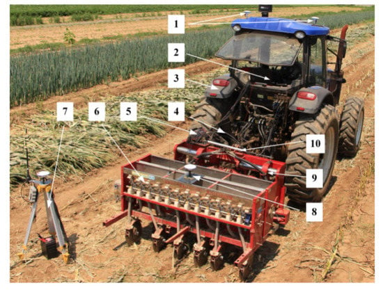
Figure 1.
The overall structure of the side-shift stubble avoidance system. Note: 1, Tractor positioning antenna; 2, Train-borne computer; 3, Tractor; 4, Hydraulic system; 5, Controller; 6, Wheat no-till seeder; 7, Base station; 8, Implement positioning antenna; 9, Side-shift mechanism; 10, Displacement sensor.
While the tractor moves steadily along the target path, the system works with the wheat no-till seeder deviating to touch the stubble because of the uneven terrain and driving inertia in the field. The real-time position provided by the information sensing system is compared with the information of the previous corn seeding row prescription map to obtain the lateral deviation of the implement. Therefore, the control system automatically adjusts the intra-row position of the furrowing and seeding assembly to avoid root stubble by the side-shift mechanism, which improves the quality of no-till seeding.
3. Information Sensing System
3.1. Deviation-Perception Fusion Technology
Deviation-perception fusion technology is the key to obtaining information deviation from the information sensing system. The technology mainly includes fusion to integrate the positioning and prescription map information, thereby obtaining implement operation deviation information in the field. Firstly, the prescription map of wheat no-till seeding was generated based on various types of data decision information, such as corn row information, operation plot location and direction line [18,19]. Furthermore, the path-tracking information of the implement was derived. Secondly, the implement positioning antenna was installed on the implement for positioning to obtain real-time location information. Finally, the lateral deviation information of the implement was obtained by comparing the path tracking information with the real-time position information of the implements for analytical computation, as shown in Figure 2.
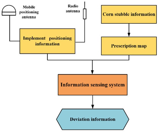
Figure 2.
Flow chart of deviation-perception fusion technology.
3.2. Calculation of Lateral Deviation Compensation Amount
Adustment of the lateral deviation compensation for wheat no-till seeders is the ultimate goal of designing an information sensing system. During the no-till operation, the wheat no-till seeder is limited by field terrain, uneven force on implements, and navigation accuracy of the tractor. However, these limitations would cause the implement to deviate from the tracking path and touch the root stubble, which directly leads to a decrease in seeding quality. As shown in Figure 3, assuming that the distance from the center of the implement to the centerline of the crop row was constant, the kinematic model of“ Tractor-Side-shift mechanism-Implement” was constructed with xoy as the plane coordinate system, and the amount of lateral deviation compensation was calculated [20,21].
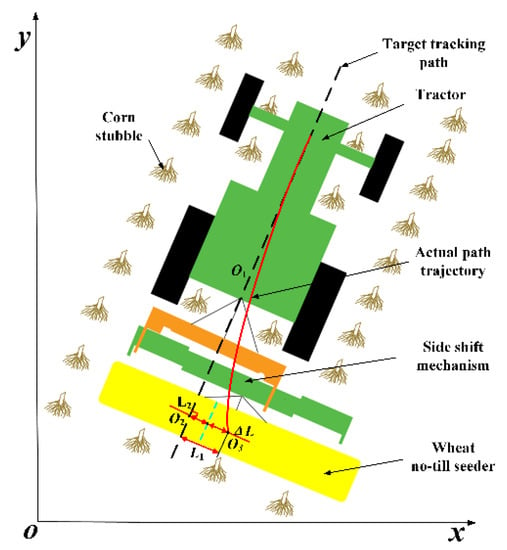
Figure 3.
Schematic diagram of the kinematic model. Note: O1 and O2 are the target positions of the tractor and wheat no-till seeder, respectively; O3 is the current position of the wheat no-till seeder; L1 and L2 are the lateral and expected deviations, respectively, mm; ΔL is the compensation amount of lateral deviation, mm.
For path tracking, the wheat no-till seeder needed to set the target tracking path before the seeding operation. The positioning coordinates O1(x1,y1) and O2(x2,y2) were obtained from the mobile station for two different position points of the tractor and the implement. The coordinates of the two location points were transformed by Gauss projection. At the same time, the straight line formed by points O1 and O2 was used as the target tracking path. Its equation could be obtained as follows.
where x1, x2, y1, y2 are the coefficients of the linear equation, x1 ≠ x2 ≠ 0, y1 ≠ y2 ≠ 0.
The current position of the wheat no-till seeder can be obtained from the information sensing system as O3(x3,y3). Therefore, the lateral deviation of the tracking path of the implement from the target can be expressed as L1.
where a, b, and c are the coefficients of the linear equation, a ≥ 0, b ≥ 0, a ≠ b ≠ 0.
Since the wheat no-till seeder operating trajectory needs to maintain a certain offset from the corn root stubble row [22,23], the expected deviation of the implement opener operation was expressed as , ≤ 50 mm. The amount of lateral deviation compensation was expressed as ΔL.
Therefore, ΔL was calculated by constructing the schematic diagram of the “Tractor-Side-shift mechanism-Implement“ kinematic model. ΔL could be used to provide decision information to the control system for precise control of the side-shift mechanism.
4. Control System
4.1. The Overall Framework of the Control System
The control system is the core of achieving automatic and accurate side-shift. As shown in Figure 4, the system includes train-borne computer, side-shift mechanism, hydraulic system, and controller. When the tractor was towed steadily along the target path, the information sensing system not only detected the distance between the wheat no-till seeder and the target path in real-time but also transmitted the detected distance signal to the controller through the train-borne computer. When there was a difference between the measured and the desired lateral deviation, the control system used fuzzy PID algorithm to correct the existing deviation. Based on the correction, the controller outputs control signals to the hydraulic system. This controller controlled the speed and distance of the hydraulic cylinder push rod through the solenoid proportional reversing valve. It caused the lateral movement of the side-shift mechanism, which changes the operation path of the implement. At the same time, the displacement sensor detects and feeds back the actual displacement of the mechanism in real-time to form a closed-loop control, so that the precise adjustment of the implement position could be realized.
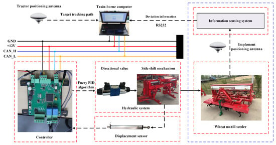
Figure 4.
The hardware framework of the control system. Note: RS232 is the serial communication interface of the controller; GND is ground; +12V is the controller power supply voltage; CAN_H is the controller high level interface; CAN_L is the controller low level interface.
4.2. Side-Shift Mechanism
The side-shift mechanism is the key component to realize the stubble avoidance of wheat no-till seeder. The mechanism is composed of a front passive frame, rear active frame, and double round axle slide rail. As shown in Figure 5, it could be hooked up with the tractor and wheat no-till seeder, respectively, through the three-point suspension mechanism at the front and rear ends. In addition, the rear active frame was connected to the front passive frame through the double circular axle slide, relative to the front passive frame lateral sliding. The longitudinal adjustment mechanism and transverse adjustment frame were connected to the lower suspension point. The operating posture of the machine was adjusted so that it compensated for the height difference caused by the ground undulation. When the implement deflection would nearly touch the root stubble, the control system adjusted the hydraulic cylinder telescopic distance according to the lateral deviation provided by the information sensing system. Furthermore, the rear active frame was pushed to deflect the implement from left to right. At the same time, the displacement sensor obtained the offset distance in real-time and gave feedback. When the implement operated in the field, the forward direction of the implement was consistent with the target tracking path, and the rear active frame did not shift laterally. When it was on the right side of the target tracking path, the rear active frame shifted to the left side. On the contrary, the rear active frame shifted to the right side.
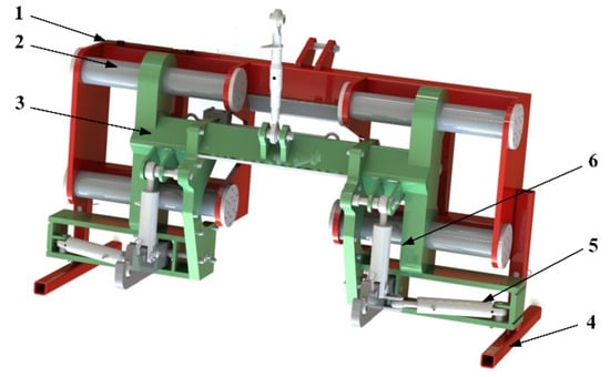
Figure 5.
Side-shift mechanism. Note: 1, Front passive frame; 2, Double circular axle; 3, Rear active frame; 4, Foot rest; 5, Lateral adjustment mechanism; 6, Longitudinal adjustment mechanism.
4.3. Hydraulic System
The hydraulic system is made up of the electro-hydraulic proportional directional valve, hydraulic cylinder, and telescopic feedback device. In addition, the hydraulic cylinder is the key executive component to achieve the deviation distance compensation of the implement, and its maximum working stroke is 250 mm. The suitable speed of the hydraulic cylinder influenced the evaluation of the side-shift stubble avoidance system [24]. The range of hydraulic cylinder speed was 20~30 mm/s. The displacement sensor is the feedback device of hydraulic cylinder expansion. The KPC1 hinge-type linear displacement sensor was selected, with a range of 0~300 mm and a resolution of less than 0.01 mm.
As shown in Figure 6, when the implement exceeds the lateral deviation, the hydraulic oil was sucked and filtered by the gear pump and then passed through the electro-hydraulic proportional directional valve to the hydraulic cylinder. Meanwhile, a relief valve was added to the system for improving the protection capacity of the hydraulic system. When the lateral deviation exceeded the expected deviation, the controller issued a command to control the relays KA1 and KA2. Then, it controlled the opening direction and flow size of the electro-hydraulic proportional directional valve. Therefore, the hydraulic system could accurately adjust the expansion speed and realized the rapid compensation of the lateral deviation of the implement.
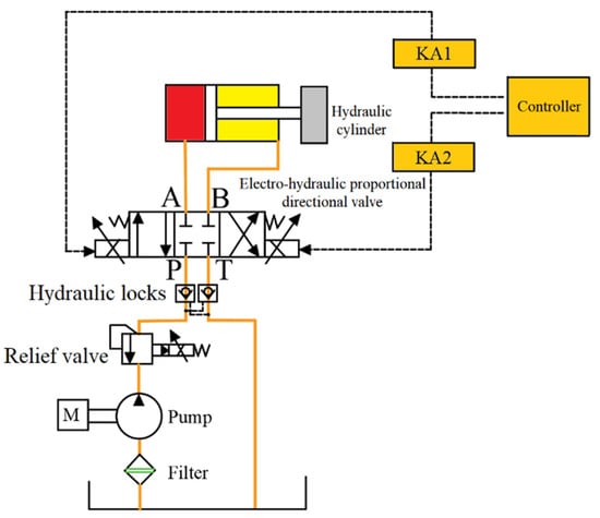
Figure 6.
Working principle diagram of the hydraulic system. Note: KA1 and KA2 are electromagnetic relays; A and B are the actuators of the hydraulic system working oil port; P is the hydraulic system actuating element oil intake port; T is the hydraulic system actuating element oil outlet port; M is the hydraulic motor of the hydraulic system.
4.4. Side-Shift Controller
4.4.1. Fuzzy PID Algorithm
During the expansion and contraction of the hydraulic cylinder, there were problems with slow response time and low control accuracy. According to the principle of PID control and fuzzy control, the stubble avoidance control method based on the fuzzy PID algorithm was proposed [25,26]. The valve control cylinder transfer function was built by a linear relationship between the current magnitude and the electro-hydraulic proportional directional valve [27]. The control law was expressed by Equation (4). If the input signal of the system was discretized, the incremental PID control equation was obtained as expressed in Equation (5).
where u(t) is the output control signal; Kp is the proportional gain; Ki is the integration coefficient; Kd is the differentiation coefficient; e(t) is the input deviation control signal; Ti is the integration time; Td is the derivative time; ∆u(k) is the increment of the output control signal.
The fuzzy PID control structure is a fuzzy logic with two inputs, three outputs and 49 rules [28,29,30,31]. The lateral deviation e and the deviation change ec of the side-shift mechanism were used as input variables. E and EC were the linguistic variables of e and ec in the fuzzy theory domain. The online adjusted parameters Kp, Ki, and Kd were used as output variables. These parameters were synthesized by linear relations with the controlled variables and then transmitted to the controller system as shown in Figure 7.
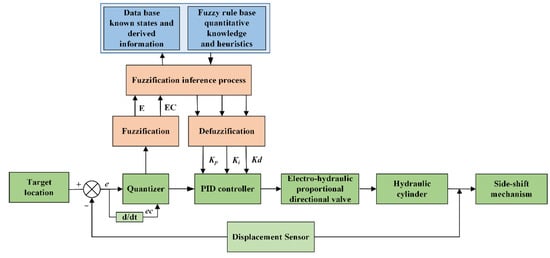
Figure 7.
Fuzzy PID structure of control system.
4.4.2. Fuzzy PID Controller
With the lateral deviation of the wheat no-till seeder as the control object, e and ec were used as the input variables of the fuzzy PID controller. The displacement of the piston rod on the hydraulic cylinder was used as the output variable to design the fuzzy PID controller. We set the forward direction of the lateral shift mechanism as negative on the left and positive on the right, and set the fuzzification process to be described by seven linguistic variables, namely, NB (negative large), NM (negative middle), NS (negative small), ZO (zero), PS (positive small), PM (positive medium) and PB (positive large). For engineering implementation, the triangular affiliation function was used in practical applications [32]. For the input variables, the affiliation degree that belonged to these 7 fuzzy sets could be calculated by the affiliation function and thus transformed into fuzzy variables. The membership function curves of two input variables and three output variables are shown in Figure 8, and the three-dimensional output surface of the fuzzy control variables Kp, Ki, and Kd are shown in Figure 9.
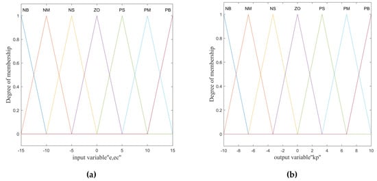
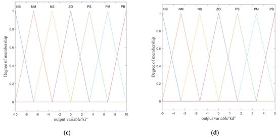
Figure 8.
The membership function curves of two input variables and three output variables: (a) Input variables e and ec; (b) Output variable Kp; (c) Output variable Ki; (d) Output variable Kd.
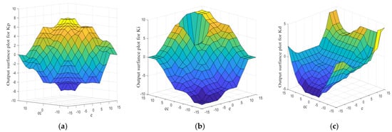
Figure 9.
The three-dimensional output surface of the fuzzy control output variables: (a) Kp output surface, input variables e and ec; (b) Ki output surface, input variables e and ec; (c) Kd output surface, input variables e and ec.
4.4.3. Controller Simulation
Based on the fuzzy PID stubble avoidance control method and the transfer function of the hydraulic system, a simulation model of the system was established using Matlab/Simulink. The model used a combination of the critical proportionality method and the trial-and-error method to adjust the parameters of the system [33]. Finally, the three parameters were respectively set as Kp = 35, Ki = 0.8, and Kd = 16.
From the simulation waveform of the step response curve in Figure 10, it could be seen that the regulation time ts2 required for the response curve to reach the steady state was 1.0 s, and the maximum overshoot Mp2 was 8.2%. Compared with PID control, the overshoot of the system with the fuzzy PID control method was reduced by 14.7%, and the time to enter the steady state was reduced by 0.9 s. Therefore, it was verified that the fuzzy PID control algorithm can quickly and steadily improve the response time of the hydraulic cylinder to reach the target position. The algorithm also further improved the dynamic performance of the side-shift stubble avoidance system.
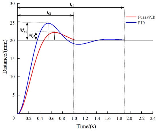
Figure 10.
The step response curve of the side-shift stubble avoidance system. Note: ts1 and ts2 are the regulation time required for the PID and Fuzzy PID response curves to reach steady state, respectively, s; Mp1 and Mp2 are the maximum overshoot of PID and Fuzzy PID, respectively, %; PID is the proportion integral differential.
5. Field Experiments
5.1. Experimental Conditions
Field tests were conducted at Zhangqiu region (36°56′ N, 117°25′ E) in Central Shan-dong on 20–25 August 2022, which is located in Huang-Huai-Hai plain of China, and the experimental equipment is as shown in Figure 1. According to the China National Standard GB/T, 20865-2017 “No or little-tillage fertilizer-seeder”, 51 areas of 15 m × 3 m were randomly selected as the area to experiment. The test field was a corn field, and the wheat planting pattern was to sow three rows of wheat at equal intervals between the rows of corn root stubble [34]. The previous crop was a maize variety; the row spacing of corn sowing was 600 mm, and the row spacing of wheat seeding was 200 mm; the soil moisture content was 12.5 % and the soil compactness was 1.25 MPa. The test instruments included an electronic scale (Shenzhen Mobil Electronics Co., Ltd., Shenzhen, China, range 0~10 kg, accuracy 0.1 g), an SC-900 Soil Compaction Meter (Spectrum Chemical Co., Ltd., Gardena, CA, USA, range 0~7 MPa, accuracy 35 kPa), a TDR 300 Soil Moisture Meter (Spectrum Chemical Co., Ltd., Gardena, CA, USA, range 0~100%, accuracy 1%).
5.2. Experimental Design and Methods
5.2.1. Response Indicators
Based on the study of the side-shift stubble avoidance system, the operational performance of the wheat no-till seeder was tested. Therefore, the stubble avoidance rate (SAR) y1 and the sowing uniformity coefficient of variation (CV) y2 were taken as evaluation indexes. Through the analysis of orthogonal test results, suitable operating scenarios and appropriate operating parameters could be determined.
After the seeding operation was completed, 3 areas of 10 m × 3 m plots were randomly selected in each test area for sampling. We recorded the number of upright root stubble left intact on the surface before and after the test in the area. The SAR was calculated as the following Equation (6).
where y1 is SAR (%), yq is the number of upright root stubble stems left intact on the ground surface in the i area before the test, yp is the number of upright root stubble stems left intact on the ground surface in the i area after the test.
After completing the planter operations, 10 areas of 100 mm plots were randomly selected within the seeding strip of each test area for sampling. Recording the number of wheat seeds in the area, the CV was calculated as the following Equation (7).
where y2 is CV (%), is the average number of wheat seeds in the i test area. N is the number of wheat seeds in the i test area.
5.2.2. Experimental Scheme and Design
Combined with the tillage characteristics of the Huang-Huai-Hai plain of China wheat-maize rotation area [1], the side-shift mechanism structural characteristics were studied and tests made in the previous period. The operation speed x1, hydraulic cylinder speed x2, and straw mulch amount x3 were taken as test factors that have a significant impact on system operational performance. According to the actual operation experience, the operation speed range was selected from 0.8 to 2.0 m/s, given the technical parameters of the wheat no-till seeder operation speed [35]. Suitable hydraulic cylinder speed was an important factor to ensure the stability of the stubble avoidance siding system. The hydraulic cylinder speed range was derived from 20 to 30 mm/s by combining the previous test and fuzzy PID simulation analysis. The straw mulch amount was related to the corn cultivars and implements. According to the actual measurement and combined with the China Industry Standard NY/T 2847–2015 “wheat no-till seeder applicability evaluation method”, the straw mulch amount was determined to be from 0.5 to 2.7 kg/m2. The amount of straw mulch on the land surface was determined by a straw grinder or manual picking during the test. Finally, each test code was determined and is shown in Table 1.

Table 1.
Code of factor levels.
5.3. Results and Variance Analysis
5.3.1. Test Results
To obtain better results in the no-till seeding operation, an orthogonal test with three factors and three levels was designed, and 17 groups of tests were completed. Each seeding test was repeated three times, and the results were taken as the average value. The test scheme and its results are shown in Table 2.

Table 2.
Test scheme and results.
5.3.2. Regression Models and Significance Test
Design-expert (Version 13) was used to perform multi-distance regression fitting analysis on the seeding test data in Table 2. The quadratic regression models of the actual values of the SAR and the CV were obtained [36,37], as shown in Equations (8) and (9).
The significance test and variance analysis were conducted for the quadratic regression models of the evaluation indexes y1 and y2, respectively, and the results are shown in Table 3. As shown by the ANOVA, the p-values of the misfit terms of both SAR and CV were not significant. The result indicates that the model had better accuracy and could accurately respond to the relationship.

Table 3.
Variance analysis of the regression models.
5.4. Impact of Significant Interactions on Evaluation Indexes
5.4.1. Impact of Significant Interactions on SAR
As shown in Figure 11a, with the level value of the straw mulch amount as 0, and when the operation speed is certain, the SAR showed a trend of first increasing and then decreasing with an increase in the hydraulic cylinder speed. Similarly, the SAR presented an obvious trend of first increasing and then decreasing with an increase in the operation speed. This result might be explained as follows. When the operation speed increased, the response interval time between two operations of the side-shift stubble avoidance system was then shortened. After the SAR reached the highest value, the chance of collision between the side-shift mechanism and stubble increased, resulting in decreased SAR.
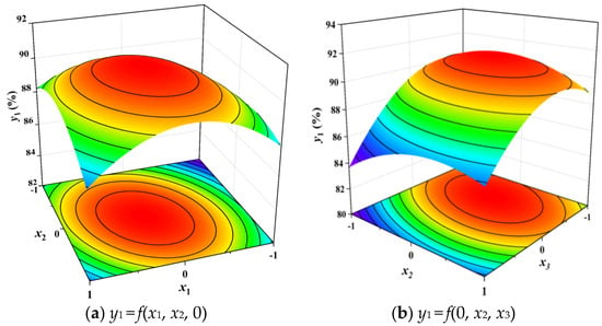
Figure 11.
Effect of interaction between factors on SAR.
As shown in Figure 11b, when the level value of the operation speed was 0, and when the hydraulic cylinder speed was certain, the SAR first slightly increased and then showed a trend of obvious decrease with an increase in the straw mulch amount. When the straw mulch amount was certain, the SAR presented a trend of first increasing and then decreasing with an increase in the hydraulic cylinder speed. This is because, when the straw mulch amount is certain, with the increase of hydraulic cylinder speed, the stubble avoidance action of the rolling colter component is frequent, increasing the system’s steady state time; thus, the SAR tends to rise and then decrease.
As shown in Figure 11, the operation speed and the straw mulch amount have a greater influence on the SAR than the hydraulic cylinder speed. A moderate operation speed should be preferred to obtain a higher SAR.
5.4.2. Impact of Significant Interactions on SAR
As shown in Figure 12a, when the operation speed is certain, and with the level value of the straw mulch being 0, the CV showed a trend of first increasing and then decreasing with an increase in the hydraulic cylinder speed. The CV presented an obvious trend of increasing with an increase in the operation speed. This was because when the operation speed increased, the operation frequency of the side-shift stubble avoidance system increased, resulting in a decrease in the uniformity of wheat seeding.
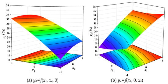
Figure 12.
Effect of interaction between factors on CV.
As shown in Figure 12b, with the level value of the hydraulic cylinder speed being 0, when the operation speed is certain, a slightly decreasing trend was shown with an increase in the straw mulch amount. Similarly, the CV presented an obvious trend of increasing with an increase in the operation speed, the SAR first slightly increased and then showed a trend of obvious decrease with an increase in the straw mulch amount. When the straw mulch amount is certain, the CV presented a trend of first increasing and then decreasing. When the straw cover between the rows or the planter speed increases, the execution speed of the side-shift stubble avoidance system did not match the current amount of straw cover between the rows or the forward speed of the implement. As a result, the seeder trenching assembly could not avoid the corn stubble in time and the sowing variation coefficient gradually increased.
As shown in Figure 12, the operation speed had a greater influence on the SAR than the extending-retracting speed and the straw mulch amount. To obtain a smaller CV, a lower operating speed could be preferred.
5.5. Parameter Optimization Analysis and Test Verification
5.5.1. Parameter Optimization Analysis
It was known from relevant studies [34] that the no-till seeding operation requires a higher SAR. The parameter optimization analysis was carried out with the weight level of SAR 5+, and the weight level of CV 1+ [38]. Optimal analysis was performed on the established second-order regression model using the data analysis software of Design Expert. The objective function and constraints of the planning were as follows.
By optimizing and solving Equation (10), the optimal combination of operating parameters that affected the SAR and the CV was obtained as follows: the operation speed was 1.3 m/s, the hydraulic cylinder speed was 25 mm/s, and the straw mulch amount was 1.2 kg/m2. In this case, the SAR was 91.2%, and the CV was 26.97%.
Since it is difficult to maintain stable operating parameters during actual operation, the operating speed and straw mulching amount were optimized and analyzed by combining the China Industry Standard NY/T 2847–2015 “wheat no-till planter applicability evaluation method” and the results of the previous tests, setting SAR greater than 90%, CV less than 30% [39,40]. According to the ANOVA, the expansion speed has less influence on the test index, setting it to 25 mm/s for parameter optimization. The optimal optimization range is shown in Figure 13. The yellow area is the area with SAR more than 90% and CV less than 30%. The gray area is the area with SAR less than 90% and CV more than 30%. Among such areas, the yellow area in the figure is the best working area.
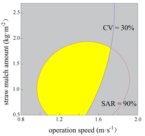
Figure 13.
Parameter Optimization Analysis Chart. Note: SAR and CV are the stubble avoidance rate and coefficient of variation, respectively, %.
The operation speed and straw mulching amount were both in the best combination as the yellow shaded area when the expansion speed was 25 mm/s. When the operation speed was 0.97~1.72 m/s and the straw mulch amount was 0.5~1.94 kg/m2, the SAR was greater than 90% and the CV was less than 30%.
5.5.2. Verification Tests
To verify the performance of the side-shift stubble avoidance system, field performance verification tests were carried out. The tests were conducted at the research base for wheat cultivation base of the Shandong Academy of Agricultural Machinery Science (Zhangqiu region, Shandong Province) on August 27, 2022. Before a single test, the working parameters were adjusted so that the operation speed was 1.3 m/s, the hydraulic cylinder speed was 25 mm/s, and the straw mulch amount was 1.2 kg/m2. The stubble avoidance by the seeder is shown in Figure 14a, and the distribution of seeds is shown in Figure 14b.
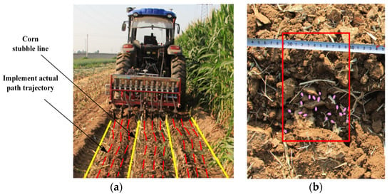
Figure 14.
Field verification and test site conditions. (a) stubble avoidance by seeder. (b) distribution of seeds. Note: The red and yellow lines are the corn stubble line and the implement actual path trajectory line, respectively.
To eliminate random errors in the field test, five groups of tests were conducted, and the test results were taken as the average value. The field verification tests showed that the Side-shift stubble avoidance system, under the optimized combination of operation parameters, had a good operating effect. The test results showed that the SAR was 90.6% and the CV was 27.12%. The relative error with the predicted values did not exceed 5%. Compared with the existing system [39], the SAR was increased by 0.6%, and the CV was reduced by 0.3%. This showed that the side-shift stubble avoidance system had good accuracy, and the side-shift stubble avoidance system can meet the practical requirements of no-till seeding operations.
6. Conclusions
According to the stubble avoidance requirement of the seeder, the side-shift stubble avoidance system of a wheat no-till seeder was developed. In this paper, using the information sensing system to obtain the deviation compensation amount of the implement, the performance of the side-shift stubble avoidance system was simulated and analyzed by using the fuzzy PID algorithm. To verify the control performance of the developed system, the orthogonal rotation test was conducted and the following conclusions were drawn.
- (a)
- This paper proposed a deviation information acquisition method based on the fusion of the implement positioning information and the prescription map crop row information. The kinematic analysis of the “Tractor-Side-shift mechanism-Implement” model was carried out, and the mathematical expression of lateral deviation was constructed to calculate the deviation compensation amount. This provides a foundation for control system decisions.
- (b)
- The controller based on the fuzzy PID algorithm was developed to build a control system for driving the side-shift mechanism to move laterally. A simulation analysis of the control system was performed. Simulation results showed that the regulation time required for the system response curve to reach the steady state under the fuzzy PID control method was 1.0 s, and the maximum overshoot was 8.2%.
- (c)
- The optimal combination of parameters was obtained through an orthogonal test with three-factor and three-level settings. The optimal operation speed was 1.3 m/s, the hydraulic cylinder speed was 25 mm/s, and the straw mulch amount was 1.2 kg/m2. Therefore, the field verification test was conducted under the optimal parameter combination. The test showed that the SAR was 90.6% and the CV was 27.12%. The results satisfied the need for stubble avoidance and seeding operations.
Author Contributions
Conceptualization, Z.Z., Q.G. and J.H.; writing—original draft preparation, Z.Z., Q.G. and J.H.; writing—review and editing, M.Z., Z.X., C.Z., H.L. and Q.W.; funding acquisition, J.H. All authors have read and agreed to the published version of the manuscript.
Funding
This research was funded by the China Agriculture Research System of MOF and MARA (Grant No. CARS-03), the 2115 Talent Development Program of the China Agricultural University, and Chinese Universities Scientific Fund (Grant No. 2021TC105).
Institutional Review Board Statement
Not applicable.
Informed Consent Statement
Not applicable.
Data Availability Statement
Not applicable.
Conflicts of Interest
The authors declare no conflict of interest.
References
- Li, H.; Liu, H.; Zhou, J.; Wei, G.; Shi, S.; Zhang, X.; Zhang, R.; Zhu, H.; He, T. Development and first results of a no-till pneumatic seeder for maize precise sowing in Huang-Huai-Hai plain of China. Agriculture 2021, 11, 1023. [Google Scholar] [CrossRef]
- He, J.; Li, H.; Chen, H.T.; Lu, C.Y.; Wang, Q.J. Research progress of conservation tillage technology and machine. Trans. Chin. Soc. Agric. Mach. 2018, 49, 1–19. [Google Scholar] [CrossRef]
- May, W.E.; Aldous, L.; Lafond, G.P. Feasibility of a wider row spacing and recommended nitrogen in no-till wheat. Agron. J. 2020, 112, 4076–4091. [Google Scholar] [CrossRef]
- Lin, H.; He, J.; Li, H.; Wang, Q.; Lu, C.; Yang, W.; Huang, S.; Liu, P.; Chang, Y. Design and experiment of a reciprocating intermittent chopping device for maize straw returning. Agriculture 2022, 12, 220. [Google Scholar] [CrossRef]
- Wang, B.; Gu, F.; Hu, Z.; Wu, F.; Chen, X.; Luo, W. Analysis and evaluation of influencing factors on uniform sowing of wheat with wide seed belt after sowing and soil throwing device. Agriculture 2022, 12, 1455. [Google Scholar] [CrossRef]
- Hou, S.Y.; Chen, H.T.; Zou, Z.; Shi, N.Y. Design and test of side-direction straw-cleaning blade for seedbed treatment of original stubble planter. Trans. Chin. Soc. Agric. Mach. 2019, 50, 41–51. [Google Scholar] [CrossRef]
- Sun, H.; Slaughter, D.C.; Ruiz, M.P.; Gliever, C.; Upadhyaya, S.K.; Smith, R.F. RTK GPS mapping of transplanted row crops. Comput. Electron. Agric. 2010, 71, 32–37. [Google Scholar] [CrossRef]
- Zhu, H.; Wu, X.; Qian, C.; Bai, L.; Ma, S.; Zhao, H.; Zhang, X.; Li, H. Design and experimental study of a bi-directional rotating stubble-cutting no-tillage planter. Agriculture 2022, 12, 1637. [Google Scholar] [CrossRef]
- Wang, Q.J.; Cao, X.P.; Wang, C.; Li, H.W.; He, J.; Lu, C.Y. Research progress of no/minimum tillage corn seeding technology and machine in northeast black land of China. Trans. Chin. Soc. Agric. Mach. 2021, 52, 1–15. [Google Scholar] [CrossRef]
- Dijksterhuis, H.L.; Van Willigenburg, L.G.; Van Zuydam, R.P. Centimetre-precision guidance of moving implements in the open field: A simulation based on GPS measurements. Comput. Electron. Agric. 1998, 20, 185–197. [Google Scholar] [CrossRef]
- Nørremark, M.; Griepentrog, H.W.; Nielsen, J.; Søgaard, H.T. The development and assessment of the accuracy of an autonomous GPS-based system for intra-row mechanical weed control in row crops. Biosyst. Eng. 2008, 101, 396–410. [Google Scholar] [CrossRef]
- Nørremark, M.; Griepentrog, H.W.; Nielsen, J.; Søgaard, H.T. Evaluation of an autonomous GPS-based system for intra-row weed control by assessing the tilled area. Precis. Agric. 2012, 13, 149–162. [Google Scholar] [CrossRef]
- Perez-Ruiz, M.; Carballido, J.; Agüera, J.; Rodríguez-Lizana, A. Development and evaluation of a combined cultivator and band sprayer with a row-centering RTK-GPS guidance system. Sensors 2013, 13, 3313–3330. [Google Scholar] [CrossRef]
- Baio, F.H.R. Evaluation of an auto-guidance system operating on a sugar cane harvester. Precis. Agric. 2012, 13, 141–147. [Google Scholar] [CrossRef]
- Feng, H.M.; Gao, N.N.; Meng, Z.J.; Chen, L.P.; Li, Y.; Guo, Y.M. Design and experiment of deep fertilizer applicator based on autonomous navigation for precise row-following. Trans. Chin. Soc. Agric. Mach. 2018, 49, 60–67. [Google Scholar] [CrossRef]
- Zhou, M.; Xia, J.; Zhang, S.; Hu, M.; Liu, Z.; Liu, G.; Luo, C. Development of a depth control system based on variable-gain single-neuron PID for rotary burying of stubbles. Agriculture 2022, 12, 30. [Google Scholar] [CrossRef]
- Yang, Y.; Li, Y.; Wen, X.; Zhang, G.; Ma, Q.; Cheng, S.; Chen, L. An optimal goal point determination algorithm for automatic navigation of agricultural machinery: Improving the tracking accuracy of the Pure Pursuit algorithm. Comput. Electron. Agric. 2022, 194, 106760. [Google Scholar] [CrossRef]
- Yin, J.; Zhu, D.; Liao, J.; Zhu, G.; Wang, Y.; Zhang, S. Automatic steering control algorithm based on compound fuzzy PID for rice transplanter. Appl. Sci. 2019, 9, 2666. [Google Scholar] [CrossRef]
- Campos, J.; Gallart, M.; Llop, J.; Ortega, P.; Salcedo, R.; Gil, E. On-farm evaluation of prescription map-based variable rate application of pesticides in vineyards. Agronomy 2020, 10, 102. [Google Scholar] [CrossRef]
- Jing, Y.; Liu, G.; Luo, C. Path tracking control with slip compensation of a global navigation satellite system based tractor-scraper land levelling system. Biosyst. Eng. 2021, 212, 360–377. [Google Scholar] [CrossRef]
- Zhang, M.N.; Yin, W.Q.; Lin, X.Z.; Lu, X.L. Method for calculating navigation parameters via RTK—DGPS fusing inertial sensor for agricultural vehicle. Trans. Chin. Soc. Agric. Mach. 2015, 46, 7–12. [Google Scholar] [CrossRef]
- Chen, W.Z.; Wang, Q.; Li, H.; Wang, X. Maize stubble row recognition and guidance line detection based on machine vision in natural illumination. In Proceedings of the 2017 ASABE International Meeting, Spokane, WA, USA, 16–19 July 2017. [Google Scholar] [CrossRef]
- Hu, L.; Luo, X.W.; Zhang, Z.G.; Chen, X.F.; Lin, C.X. Side-shift offset identification and control of crop row tracking for intra-row mechanical weeding. Trans. Chin. Soc. Agric. Mach. 2013, 29, 8–14. [Google Scholar] [CrossRef]
- Yu, C.C.; Xu, L.M.; Wang, Q.J.; Yuan, Q.C.; Ma, S.; Niu, C.; Yuan, X.T.; Zeng, J.; Wang, S.S.; Chen, C. Design and experiment of bilateral operation intra-row auto obstacle avoidance weeder for trellis cultivated grape. Trans. Chin. Soc. Agric. Eng. 2019, 35, 1–9. [Google Scholar] [CrossRef]
- Yao, Y.F.; Chen, X.G.; Ji, C.; Chen, J.C.; Zhang, H.; Pan, F. Design and experiments of the single driver for maize precision seeders based on fuzzy PID control. Trans. Chin. Soc. Agric. Mach. 2022, 38, 12–21. [Google Scholar] [CrossRef]
- Wang, W.; Wu, K.; Zhang, Y.; Wang, M.; Zhang, C.; Chen, L. The development of an electric-driven control system for a high-speed precision planter based on the double closed-loop fuzzy PID algorithm. Agronomy 2022, 12, 945. [Google Scholar] [CrossRef]
- Cheng, Z.; Lu, Z. Research on load disturbance based variable speed PID control and a novel denoising method based effect evaluation of HST for agricultural machinery. Agriculture 2021, 11, 960. [Google Scholar] [CrossRef]
- Xu, Q.; Li, H.; Wang, Q. Wheel deflection control of agricultural vehicles with four-wheel independent omnidirectional steering. Actuators 2021, 10, 334. [Google Scholar] [CrossRef]
- Lin, T.; Huang, W.; Ren, H.; Fu, S.; Liu, Q. New compound energy regeneration system and control strategy for hybrid hydraulic excavators. Autom. Constr. 2016, 68, 11–20. [Google Scholar] [CrossRef]
- Wang, R.; Tan, C.; Xu, J.; Wang, Z.; Jin, J.; Man, Y. Pressure control for a hydraulic cylinder based on a self-tuning PID controller optimized by a hybrid optimization algorithm. Algorithms 2017, 10, 19. [Google Scholar] [CrossRef]
- Chen, W.; Wang, G.; Hu, L.; Yuan, J.; Wu, W.; Bao, G.; Yin, Z. PID-Based design of automatic control system for a travel speed of the 4UM-120D Electric Leafy Vegetable Harvester. Sustainability 2022, 14, 14066. [Google Scholar] [CrossRef]
- Han, B.; Yang, Y.N.; Wang, H.W.; Fan, W. Design of PID automatic control system for depth into earth of intra-row weeding components and its bench experiment. Trans. Chin. Soc. Agric. Mech. 2018, 34, 68–77. [Google Scholar] [CrossRef]
- Liu, W.J.; Luo, X.W.; Zeng, S.; Zeng, L. Performance test and analysis of the self-adaptive profiling header for ratooning rice based on fuzzy PID control. Trans. Chin. Soc. Agric. Eng. 2022, 38, 1–9. [Google Scholar] [CrossRef]
- Zhang, Z.G.; Guo, Q.F.; He, J.; Li, H.W.; Wang, Q.J.; Zeng, C. Design and experiment of a double-guide sliding deflection system for No-till wheat seeder. Trans. Chin. Soc. Agric. Mach. 2022, 53, 80–90. [Google Scholar] [CrossRef]
- Hou, S.Y.; Wang, S.; Ji, Z.; Zhu, X. Design and Test of the Clearing and covering of a minimum-tillage planter for corn stubble. Agriculture 2022, 12, 1209. [Google Scholar] [CrossRef]
- Ren, L.Q. Experiment Optimization Design and Analysis; Higher Education Press: Beijing, China, 2003. [Google Scholar]
- Liang, R.; Zhang, B.; Zhou, P.; Li, Y.; Meng, H.; Kan, Z. Cotton length distribution characteristics in the shredded mixture of mechanically recovered residual films and impurities. Ind. Crops Prod. 2022, 182, 114917. [Google Scholar] [CrossRef]
- Lin, J.; Zhang, T.J.; Tian, Y.; Gao, W.Y.; Qi, L.; Li, B.F. Optimization and experiment on bionic deep-buried device for returning straw in field. Trans. Chin. Soc. Agric. Mech. 2018, 49, 50–59, 67. [Google Scholar] [CrossRef]
- Wang, C.L. Study on Automatic Stubble Avoidance and Wheat Minimum-Till Seeder in Maize Stalks Cover Field; China Agricultural University: Beijing, China, 2022. [Google Scholar]
- Chen, W.Z. Study on Maize Stubble Avoidance Technology Based on Machine Vision for Row-Follow No-Till Seeder; China Agricultural University: Beijing, China, 2018. [Google Scholar]
Disclaimer/Publisher’s Note: The statements, opinions and data contained in all publications are solely those of the individual author(s) and contributor(s) and not of MDPI and/or the editor(s). MDPI and/or the editor(s) disclaim responsibility for any injury to people or property resulting from any ideas, methods, instructions or products referred to in the content. |
© 2023 by the authors. Licensee MDPI, Basel, Switzerland. This article is an open access article distributed under the terms and conditions of the Creative Commons Attribution (CC BY) license (https://creativecommons.org/licenses/by/4.0/).