Abstract
In order to solve the problem of high labor intensity of a traditional pontoon lotus root machine with manual pushing operation, a riding pontoon digging lotus root machine was proposed in this paper. The working principle of the digging machine was introduced, the key components were designed, and the buoyancy of the pontoon was calculated and analyzed. The performance of the digging machine was tested in a lotus root pond, the lotus root digging rate was 76%, and hydraulic flushing generated by the digging machine can disperse the soil within 30 cm under water. In addition, the best flushing effect was achieved when the number of working nozzles was controlled to three. Finally, according to the test results, the optimization measures of the hydraulic lotus root digging machine were proposed, and the CFD-DEM coupled simulation model was used to simulate and analyze the soil disturbance effect of hydraulic flushing upward from the bottom of the lotus root. The results showed the relationship between nozzle diameter, angle and hydraulic flushing depth. When the nozzle angle was fixed, the soil disturbance effect decreased with increasing flushing depth and increased with decreasing nozzle diameter. When the nozzle depth was fixed, both the diameter and the angle had a significant effect on the soil disturbance effect. When the nozzle diameter was fixed, the interaction of angle and depth had no significant effect on the soil disturbance effect.
1. Introduction
Lotus root is one of the largest aquatic vegetables in China. According to statistics, the planting area of lotus root in China was about 500 to 700 thousand hm2 in 2014 [1]. With crispy flavor and rich nutrition, lotus roots are loved by Chinese people, which brings huge economic benefits. As the number of planters and the planting area of lotus roots have increased year by year, a manual harvesting method no longer meets the market demand. Thereby, mechanized harvesting for lotus roots needs to be realized as soon as possible [2].
Along with the further adjustment of rural economic structure, and the agricultural sector of China attaching great importance to characteristic agricultural products, the lotus root planting area has increased year by year. However, lotus root growing under deeper mud mainly relies on manual digging; thus, large labor intensity, bad working environment, low production efficiency, and poor product quality have become the bottleneck of lotus root harvest and production. To solve the above problems, in view of higher cost and tedious operating processes of the existing digging lotus root equipment, a spin-jet flow type lotus root digging machine was developed by Wu [3], to simplify digging processes and to lower the production cost. A wide-width hydraulic scouring system was designed based on a self-propelled lotus root harvester [4].
Lotus roots are mostly planted in low-lying and rotten fields with deep silt [5]. When maturing, lotus roots can be dug out from the silt layer. With fragile texture and slender shape, the harvesting method for dry land plants such as potato and water chestnut is not suitable for lotus roots, which brings too much damage to the lotus root. At present, hydraulic flushing or scouring has been proven to be the most effective method for lotus root digging, which has been widely used in harvesting machines for lotus roots [6,7,8,9,10,11,12]. However, the lotus root harvester application is largely restricted by the low harvesting rate, especially after hydraulic scouring, in which some mature lotus roots are still partially buried in the soil [13]. A new type of self-propelled lotus root harvesting machine was developed; the equipment combined two types of picking and jetting, adopting a special customized chassis heightening crawler tractor [14,15]. A water jet lotus root digging machine with a width of 4 m was designed based on a large single pond area. The phenomenon of nonuniform outlet water pressure exists due to many embranchments of a width lotus root digging machine. This will cause unpicking and injury of lotus root [16].
There are two main ways to build a hydraulic lotus root digging machine: boat type and pontoon type. The boat-type lotus root digging machine is self-propelled, which is suitable for deep-water fields [2]. The impellers driven by the internal combustion engine drive the boat to walk in the field. Meanwhile, the jet mechanism reciprocally scours the underwater sludge, making the lotus roots separate from the sludge and float out of the water. Nevertheless, due to the disadvantages of large volume, difficulty of transfer and high manufacturing cost, the boat-type lotus root digging machine is not applicable for the intensive lotus root planting mode in most regions of China. Accordingly, in order to adapt to the intensive planting mode and to achieve the purpose of saving time and labor, light and simplified lotus root digging machines are more acceptable for lotus root growers in China. For this reason, the pontoon-type lotus root digging machine emerges. The pontoon chassis is employed in current pontoon-type lotus root digging machines, which provides buoyancy in the lotus root field [17]. In addition, high-pressure water guns are used in the machines to generate water jets, driving the machines to walk in the field. Pontoon-type lotus root digging machines characterize simple operation and convenient transition. However, the operators need to walk in the field to control the frame handrail to adjust the walking direction. The heavy adhesion of paddy soil in southern China makes it difficult for operators to walk in the paddy field, which increases labor consumption.
In view of the above problems, in order to reduce the labor consumption of the operating equipment, this paper proposed a riding pontoon lotus root digging machine based on the principle of hydraulic flushing. The structure was designed, and the working principle was illustrated. Then, a pool test was carried out to analyze the working performance of the machine, and a lotus root pond test was employed to verify the working effect of the machine. Finally, according to the arising problems from the test, the optimization measures and the CFD-DEM-coupled simulation model were proposed to improve the design of the hydraulic lotus root digging machine.
2. Materials and Methods
2.1. Lotus Root and Soil Material Characteristics
Soil firmness refers to the compactness of the arrangement of soil particles, also known as soil compactness or mud penetration resistance. In the process of digging lotus root, the impact pressure of the water jet will cause different degrees of damage to the lotus root. According to the different impact positions of the lotus root in the soil, the destructive force of the lotus root damage can be divided into compression force and bending force. Due to the low power of the water pump, the water jet pressure belonged to the low level. In order to avoid nozzle clogging, the nozzle diameter was large and the low pressure was not enough to cause shear damage to the lotus root skins; thus, the effect of shear force was not considered.
Ten areas were evenly selected and the muds were collected in the lotus root pond. The mud penetration resistance at different depths of 0.1, 0.2, 0.3, and 0.4 in each area was measured by TJSD-750 soil firmness measuring instrument as shown in Table 1.

Table 1.
Mud penetration resistance.
As shown in Table 2, the lotus root compression strengths were measured by FTC TMS-Pro texture analyzer. In order to determine the maximum pressure on the surface of the lotus roots that does not damage the lotus roots during hydraulic digging, ten lotus roots are randomly selected as the test samples. Testing the compression strength of the lotus root would provide a basis for the design and optimization of the key components of the lotus root digging.
Table 2.
Compression strength of lotus root.
2.2. Prototype Design
2.2.1. Working Principle of the Lotus Root Digging Machine
The riding pontoon hydraulic lotus root digging machine is mainly composed of the gasoline engine pump set, the frame structure, the pontoon component, the hydraulic flushing device, and the driving component, as shown in Figure 1. The frame provides support and an installation platform for other parts of the machine. The pontoon component is fixed with the frame to provide buoyancy for the whole machine. The operator sits on the front seat of the frame to drive the machine.
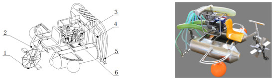
Figure 1.
The lotus root digging machine: (1) driving component, (2) frame, (3) gasoline engine pump set, (4) hydraulic flushing device, (5) pipelines, (6) reservoir.
The length and width of the whole machine are 1850 and 1770 mm, respectively, with all the component and devices included. When the machine is working in a lotus root pond, the two pontoons produce buoyancy to make the machine float on the water surface. The operator sits on the front seat of the frame, stepping on the driving pedal with both feet to drive the driving wheel to move forward. By turning the steering rod above the driving wheel, the direction of the machine can be controlled. The hydraulic flushing device is driven by the gasoline engine pump set with the power a 7.5 hp, and the water in the lotus root pond is sucked in the through pumping pipes. Before entering the reservoir, the water is filtered by a filter screen, and then, the water can be transported to the jet pipelines via a water distributor. Nine nozzles are mounted at the end of the pipelines. The water is finally flushed by the nozzles to the sludge layer to complete the hydraulic scouring. The technical parameters of the lotus root digging machine are shown in Table 3.
Table 3.
Technical parameters of the lotus root digging machine.
2.2.2. Design of the Frame Structure
The frame is the main component of the digging machine, with a length of 790 mm, and a width of 960 mm, as shown in Figure 2. The function of the frame is to install the gasoline engine water pump set, the driving component, the hydraulic flushing device, and to provide buoyancy for the whole machine. The design must consider that it should have high load-bearing capacity and deformation resistance. The frame consists of two pontoons and four square tubes. The front square tube is installed with the seat, and the float rails are installed on both sides of the pontoon. When the front end load is heavy, the position of the float ball can be adjusted to provide the front end buoyancy of the machine. The end rail is used for installation of a hydraulic flushing device.
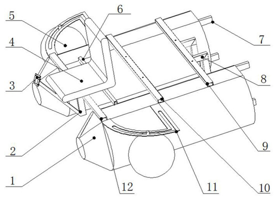
Figure 2.
The frame structure of the digging machine: (1) pontoon, (2) drive wheel bracket, (3) fixed clip, (4) seat, (5) float, (6) seat rear support square tube, (7) guide rail, (8) hanging rod, (9) unit rear support square tube, (10) unit front support square tube, (11) float guide, (12) seat front support square tube.
2.2.3. Design of the Pontoon Component
The pontoon component is fixedly connected to the frame, and the structure is shown in Figure 3. In order to provide buoyancy of the machine and the operator, the structure with two pontoons is adopted, and the length l and height H of each pontoon is 1000 and 385 mm, respectively. The main body of the pontoon is similar to the cylindrical front end with a certain taper; the selected material is 304 stainless steel. A plane with a width h of 150 mm is folded at the upper end for welding the square tube of the frame. A round table is welded on the forward end face of the pontoon to reduce the forward resistance in the water. The round table height is 150 mm, the diameter of the small end face d is 150 mm, and the radius of the cylindrical part R is 200 mm.
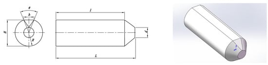
Figure 3.
Structure of the pontoon.
The mathematical relationship can be obtained from Figure 3 as shown below:
Thus, θ can be expressed as
Since h = 150 mm and R = 200 mm, substituting the values into Equation (2), θ can be calculated as 44.05°. From the Pythagorean theorem, H = 385 mm. Accordingly, the structural parameters of each pontoon can be obtained, as listed in Table 4.
Table 4.
Structural parameters of the pontoon.
Therefore, the area of the pontoon is given by
The volume of the pontoon can be obtained as
Hence, the volume of each pontoon can be calculated as 0.134 m3. According to Archimedes Law, the buoyancy of each pontoon can be given by
where Ff denotes the buoyancy of the pontoon, ρ represents the density of water, and Vd is the volume of water discharged from the pontoon.
The two pontoons are designed to provide buoyancy for the machine. It is estimated that the machine is not more than 100 kg. The weight of the 95th percentile of a Chinese adult male is about 75 kg, which indicates that the machine needs the buoyancy of at least 1750 N to float in the water field. From the equations above, the two pontoon components can provide 2680 N buoyancy. The maximum buoyancy is greater than the estimated weight of the whole machine, and the pontoon buoyancy can ensure that the whole machine can float on the water surface.
Since the operator will sit in the front of the machine, the machine can easily sink forward. Hence, a floating ball is also installed on each side of the pontoon to increase the buoyancy of the frond end of the machine. The floating ball is connected with each pontoon through a guide rail, which can move in the groove, thereby adjusting the buoyancy of the machine.
2.2.4. Design of the Hydraulic Flushing Device
The foldable hydraulic flushing device is the main working component, which is designed with a width of 1600 mm and a height of 550 mm, as shown in Figure 4. The main body of the device is made up of two adjustable guide rails, which are installed on the frame by welding. The device consists of three nozzles on the left, the middle and the right, for a total of nine nozzles. Each nozzle is made of a stainless steel pipe with connections to the nozzle plate by bolts. Both movable nozzle plates are connected with the distance adjustable rail guides via hinges, which can be folded and released by pulling the pull rods. All nozzles are connected to the water distributor by a steel pipe with an inner diameter of 32 mm.
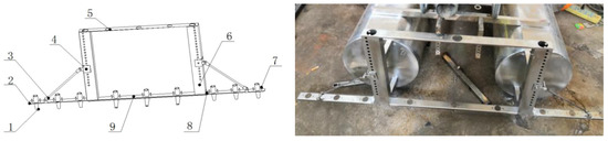
Figure 4.
The hydraulic flushing device: (1) nozzle, (2) folding board, (3) pull rod, (4) slider mechanism, (5) nozzle upper plate, (6) distance adjustable rail guide, (7) screw, (8) hinge, (9) fixed nozzle plate.
Through the slider mechanism, the hydraulic flushing device is designed to be foldable and retractable, which can control the retraction of the left and right six nozzles to save space and to facilitate transportation. When it is working, the device can realize simultaneous operation of nine nozzles with the movable nozzle plates released. With an adjustable folding board, the maximum working width of the device can be fulfilled to 1.6 m, in contrast to the working width of 1 m of the existing pontoon lotus root digging machines.
The spraying angle of the three nozzles in the middle is 45°, the spacing is 210 mm, while the six nozzles on the left and right outer sides are perpendicular to the water surface while the spacing is 150 mm.
2.2.5. Driving Componen
Pushing by hand is the traditional way to operate pontoon digging lotus root machines. In the digging process, high water level and deep mud make it difficult for an operator to walk in the lotus root pond. Therefore, a human-driven wheel of the digging machine was developed in this paper. As depicted in Figure 5, the driving component is mainly composed of a paddy wheel, two pedals and a steering rod. The paddy wheel consists of eight blades, and each blade is designed to be 170 mm long, 100 mm wide and 2 mm thick. To operate the machine, the operator needs only to sit on the front seat of the machine, control the steering rod and step on the pedals to drive the machine to move forward or to make a turn in the lotus root pond.
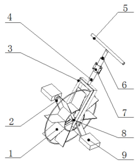
Figure 5.
Structure of the driving component: (1) blade, (2) pedal crank, (3) front bracket, (4) front fork sleeve, (5) steering rod, (6) front fork tube, (7) upper clip, (8) central axis, (9) pedal.
2.2.6. Power System and Energy Loss
The high-pressure hydraulic lotus root digging machine adopts a double pontoon structure. The digging machine needs to reduce the weight of the machine as much as possible under the premise of meeting the digging requirements. After inquiring about relevant information and field investigations, it was found that the size of the water pump used by lotus root farmers for manually hand-held water guns for digging lotus roots is mostly a 3 or 4-inch water pump. The pressure is enough to flush the lotus root out of the mud. Considering the weight, power and manufacturing cost of the whole machine, a 3-inch engine water pump set was selected as the power source of the lotus root digging machine.
The engine water pump set is a common centrifugal pump. Its working principle is that under the action of the centrifugal force generated by the high-speed rotation of the impeller, the water in the impeller channel is thrown around and pressed into the volute. At this time, the air at the impeller inlet is exhausted. Under vacuum, the fluid is sucked into the impeller channel through the pump inlet under the action of atmospheric pressure. The impeller rotates at high speed; thus, the fluid can be sucked and discharged continuously. The pump is not only light in weight and meets the weight requirements of lotus root digging machines, but it also has low cost, convenient maintenance, good low-temperature startability, and can adapt to the low-temperature environment at work. The specification parameters of the centrifugal pump are shown in Table 5.
Table 5.
Centrifugal pump parameters.
As shown in Figure 1 and Table 5, the 7.5 hp, maximum flow rate of 88 m3/h, and maximum head of 27 m gasoline engine water pump set is used to provide the water pressure of the hydraulic flushing device, each nozzle using a steel tubular manifold to reduce the head pressure loss. According to the specifications and parameters of the engine water pump set, the outlet pressure is estimated to verify whether the pressure value meets the requirements of lotus root digging. From Equation (6) of the relationship between the pump outlet pressure and lift head, the maximum outlet pump pressure is 0.27 MPa.
H—lift head; p1, p2—pressure at inlet and outlet of the pump, respectively; v1, v2—velocity at inlet and outlet of the pump, respectively; z1, z2—height at inlet and outlet of the pump, respectively; ρ—density; g—gravity acceleration.
The loss along the pipeline of the lotus root digging machine is mainly consumed in the outlet pipe, and the loss is 0.36 m. When the fluid passed through the piping components and the piping connectors, the local resistance concentration caused local losses. In the process of fluid flow, due to the sharp changes in the boundary area, such as at the bend where the flow direction changes, at the reduced diameter where the pipe diameter changes, and at the valve where additional resistance is generated, the energy loss was caused by the existence of local resistance. For the digging machine, the local loss mainly existed at the three water separators and the nozzles. For the local loss at the water inlet that was a sudden expansion of pipe diameter, the total local loss at the water pump manifold was 0.32 m.
Unlike the sudden reduction in the size of the structure, the shape of the nozzle was gradually reduced from large to small, its local energy loss is similar to the reducer model, and the local energy loss of nozzle is 2.76 m. Thus, the total energy loss is 3.08 m and the actual lift head of the pump is 23.56 m. In the test, taking into account the pressure loss in the pipeline and the influence of impurities, the outlet water pressure of each nozzle measured by the pressure sensor is about 0.20–0.23 MPa, which ensures that the pressure of each nozzle is consistent.
3. Prototype Test
3.1. Buoyancy and Driving Test
After the main structure of the machine is manufactured, the engine pump set is installed on the upper part of the pontoons, and the hydraulic flushing device is welded onto the end of the pontoon. The buoyancy of the pontoons is tested in a water pool with a depth of 30 cm, as shown in Figure 6.
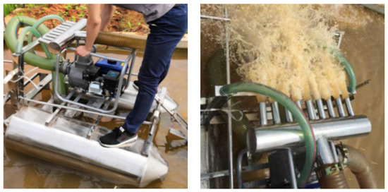
Figure 6.
Buoyancy pool test.
The driving component performance test is conducted to verify the feasibility of the driving method. The test site is a pond in Huazhong Agricultural University, with a water depth of about 40 cm, as shown in Figure 7. In the test, one operator rides on the front of the lotus root digging machine, steps on the paddy wheel pedal and controls the steering rod to drive the machine forward. The test results show that the designed lotus root digging machine has the better floating performance and driving effect compared with the hand-push machine and can reduce labor intensity. The average speed was measured to be 0.2 m/s for one round trip.
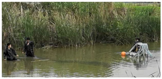
Figure 7.
Driving test site.
3.2. Lotus Root Pond Digging Test
The lotus root digging machine is employed to harvest lotus roots in a lotus root pond. Taking the digging rate and scouring depth as the test indexes, the working performance of the digging machine is tested.
A lotus root pond from comprehensive experimental base of high efficiency cultivation technology of aquatic vegetables was chosen as the experimental site, which was put into use in the first year and is located in Jiangxia District, Wuhan City, Hubei Province, China. The soil and mud in the lotus field is relatively sticky, and a test area of 5 × 5 m was selected, as shown in Figure 8.
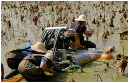
Figure 8.
Test site.
The working performance of the prototype is evaluated by digging rate and flushing depth.
- (1)
- Digging rate
According to the lotus root yield of the total field, the lotus root yield in the selected test area can be evaluated, and the digging rate is defined as the ratio of the actual digging quality of lotus roots to the yield in the test area. Assuming that the area of the total field and the test area are At and Ac, and the yield of the total field is mt, the yield in the test area can be evaluated by
where me is the yield of the test area. Therefore, the digging rate can be given by
where rd denotes the digging rate, and ma is the actual mass of the excavated lotus roots in the test area.
The total mass of the lotus roots can be weighed after the prototype is fully flushed in the 5 × 5 m test area. After that, the digging rate of the lotus root can be calculated according to the given equations.
- (2)
- Flushing depth
The hydraulic flushing device of the machine has nine nozzles with a working width of 1.6 m. The pipes are fixed by clamps, and during the test process, the closed nozzles are used to replace the original nozzles to adjust the number of working nozzles. The flushing depth under different numbers of working nozzles were tested [18].
3.3. Results and Discussion
In the chosen test area, lotus roots with a weight of 72 kg are finally harvested. The yield of the total field is about 2500 kg per mu (1 mu ≈ 666.67 m2), which was provided by the local administrator. Meanwhile, the area of the total lotus root pond is about 1330 m2. Accordingly, it can be estimated that the empirical weight of lotus roots in the selected test area is 94 kg. Finally, the theoretical digging rate is 76%. Compared to the existing design [14,15], this riding pontoon lotus root digging machine has less labor intensity with less machine weight.
Table 6 shows the relationship between the number of nozzles and flushing depth. It was found that the hydraulic flushing from the nozzles can break away the soft mud layer at a depth of 30 cm. Beneath 30 cm, the hard mud layer characterizes relatively high hardness and uneven distribution. Since the flushing depth of each nozzle is different, it is difficult to completely realize the automatic floating of the lotus roots, which need to be pulled out manually to complete the harvest. It was also observed that the maximum depth increased with a decreasing number of nozzles, including the pressure of hydraulic flushing. The results in Table 6 reveal that three working nozzles can achieve the best working performance, with larger hydraulic pressure and deeper flushing depth. In addition, three working nozzles can guarantee that the clamp will not fall off.
Table 6.
Relationship between the number of nozzles and the flushing depth.
4. Problems and Discussion
4.1. Blocking of the Filter System
The hydraulic lotus root digging machine needs to absorb water from the lotus root pond. Since many impurities such as duckweed exist in the pond, it is necessary to filter the water before entering into the pump system. The prototype uses a square filter with mesh to filter the water sucked by the pump, as shown in Figure 9. In the prototype design, the nozzles are located behind the filter device, and the distance between them is relatively short. When the nozzles are scouring the sludge, the surrounding water will mix with sediment and lotus impurities. In addition, during the suction process, the mixture partially accumulates on the mesh of the filter box and gradually blocks the mesh. With the aggravation of mesh blockage, the water inflow of the pump is insufficient, resulting in a decrease in the pressure and flow from the nozzles, which further affects the hydraulic flushing effect.
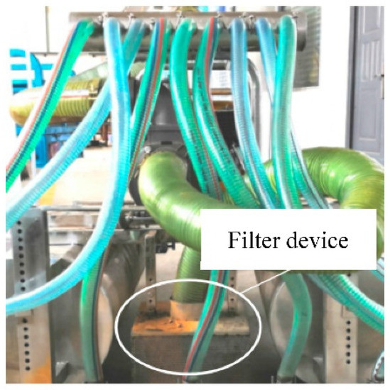
Figure 9.
Filter device.
Furthermore, a part of the water containing impurities is sucked into the pump, leading to insufficient water inflow after the machine is working for a long time. The impurities inhaled will damage the pump, influencing the service life of the pump and weakening the flushing effect as well. Figure 10 depicts the blockage of the pump.
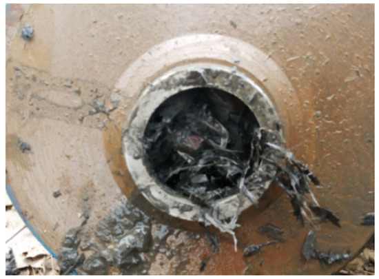
Figure 10.
Blockage of the pump.
Instead of the water pump, a mud pump or a slurry pump can be used for the lotus field environment. However, with large volume and mass, this type of mud or slurry pump is not suitable for a small pontoon lotus root digging machine. In addition, the distance between the nozzles and the suction pipe could be increased to reduce the blockage at the suction position. Since fixed nozzles show a poor flushing effect on long lotus roots, the nozzles can be improved into the movable type or can be flushed from the bottom of the lotus root. Finally, a linear guide rail, linear bearing, electric push rod and a battery can be employed on the digging machine. The linear guide rail can be installed on the rearward of the machine, and the nozzles can be hung on the rail by linear bearings. Hence, the linear reciprocating flushing can be fulfilled by the electric push rod.
4.2. Incomplete Flushing of the Fixed Nozzles
With a slender shape, the length of the main varieties of lotus root can reach more than 1 m. With many branches in addition to the trunks, the growth of lotus roots in the mud layer shows a status of disorder. In order to make each lotus root float automatically after hydraulic flushing or to pick up the lotus roots easily, the mud layer above the lotus roots should be flushed away in the length direction of each lotus root. Since the hydraulic flushing device is fixed to the machine body, the nozzles only flush the mud above the lotus root, as shown in Figure 11. Sludge still exists between adjacent nozzles, and as a result, the bottom of the lotus root is still bound by the sludge and needs to be manually pulled out. To improve the digging rate and to reduce the operator manpower, it is necessary to analyze the effect of the nozzle flushing upward from the bottom of the soil, as shown in Figure 12.
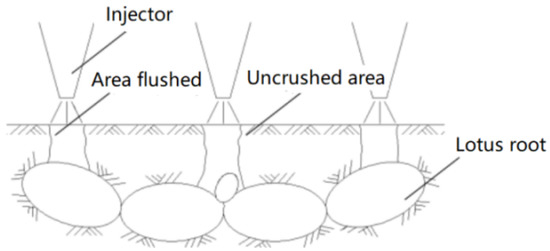
Figure 11.
Status of the lotus root during hydraulic flushing process.
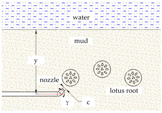
Figure 12.
Schematic diagram of lotus root bottom flushing.
The nozzle angle, diameter and depth will affect the hydraulic flushing through the pond test. Thus, the three levels of nozzle angle set at angles 30°, 45° and 60°, respectively, with the each mud surface depth at 350, 400, 450 mm, and the fluid-solid coupling test level and factor set as shown in Table 7, to simulate the performance of hydraulic flushing at the bottom of the lotus roots. The effect of soil disturbance η by hydraulic flushing is defined as the ratio of the mass of soil particles in the upper layer of the mud surface to the mass of total soil particles after jet disturbance.
Table 7.
Table of levels and factors for fluid–solid coupling test.
In order to solve the phenomenon that the existing nozzle can only flush the soil above the lotus root. A CFD-DEM-based study of the mechanism of submud hydraulic flushing is simulated, and the quadratic regression orthogonal experiment is designed to explore the appropriate operating parameters.
The simulation time of 1 s is set in the EDEM software, and each group of tests is carried out according to the test protocol. After the simulation, a vertical plane is made along the centerline of the nozzle, and the granular bed of each test group is dissected to visually observe the effect of hydraulic flushing on soil disturbance, as shown in Figure 13. The annotations in each subfigure indicate the nozzle diameter, angle and depth, respectively. In Figure 13a, when the angle between the nozzle and the horizontal direction is 30°, among the three different nozzle angles, the horizontal thrust distance is the farthest, and the vertical thrust height is the lowest. In Figure 13b, the nozzle angle 45° from the horizontal direction has the medium distance of horizontal thrust and vertical thrust height on the soil. In Figure 13c, the nozzle angle 60° has almost no horizontal thrust effect on the soil particle bed, but its vertical thrust height is the highest. It can be seen in different nozzle diameters and depths that the soil is disturbed by the effect and the trends are consistent, that is, the angle between the nozzle and the horizontal direction has a significant effect on horizontal and vertical thrust of the soil.
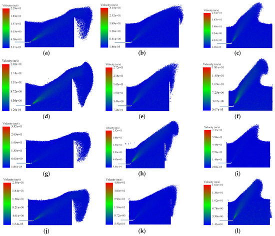
Figure 13.
CFD-EDEM simulation results. The annotations in each subfigure indicate the nozzle diameter, angle and depth, respectively: (a) 6 mm × 30° × 400 mm, (b) 6 mm × 45° × 350 mm, (c) 6 mm × 60° × 400 mm, (d) 8 mm × 30° × 350 mm, (e) 8 mm × 45° × 400 mm, (f) 8 mm × 60° × 350 mm, (g) 8 mm × 30° × 450 mm, (h) 10 mm × 45° × 450 mm, (i) 8 mm × 60° × 450 mm, (j) 10 mm × 30° × 400 mm, (k) 10 mm × 45° × 350 mm, (l) 10 mm × 60° × 400 mm.
Taking the diameter 6 mm, angle 45° and depth 450 mm as an example, the soil granular bed quality results are shown in Figure 14. The soil disturbance effect of the mud subhydraulic flushing obtained and the η = 26.13%. Based on the Box–Behnken design (BBD), the results as shown in Table 8.
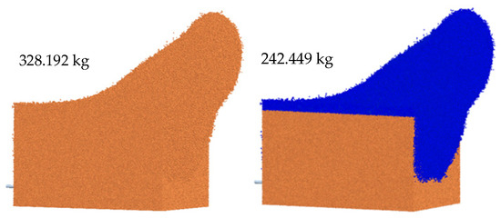
Figure 14.
Soil granular bed quality statistics.
Table 8.
Results of fluid–soil coupling test.
When the results from the above table are imported into Design-Expert for regression fitting, the regression equation with the soil disturbance η as the response value and c, γ and y as the variables is obtained.
When an analysis of variance is performed on the regression model, results shown in Table 9 are produced. The regression equation determinant R2 = 0.9949, and the p < 0.0001, indicating that the equation fit is high, the regression equation is significant, and the relationship between factors and indicators can be described. The primary terms c, γ, y, and quadratic terms c2 of the model are extremely significant, while the quadratic terms γ2 and the interaction term cγ are significant.
Table 9.
Analysis of variance for fluid–soil coupling test.
When the angle between the nozzle and the vertical direction is at a fixed value, the soil disturbance effect decreases with the increase in nozzle depth, and it increases with the decrease in nozzle diameter. Both of them have significant influence on the disturbance effect.
When the nozzle depth is fixed, the interaction between the diameter and the angle has a significant effect on the soil disturbance effect. When the diameter of the nozzle is a fixed value, as the nozzle angle increases, the disturbance effect first increases and then decreases. When the nozzle angle is a fixed value, with the decrease in the diameter, the soil disturbance effect tends to increase.
When the nozzle diameter is a fixed value, the interaction of angle and depth has no significant effect on the soil disturbance effect. When the depth is a fixed value, the disturbance effect increases with the increase in the nozzle angle. When the nozzle angle is a fixed value, the disturbance effect decreases with the increase in depth, and the depth of the nozzle affects the disturbance effect greater than that of the nozzle angle.
5. Conclusions
(1) A riding pontoon hydraulic lotus root digging machine was proposed in this paper. Compared with the traditional manual pushing operation, a pedal-driven component is employed in the digging machine, which was demonstrated to reduce the labor intensity in the operation process. The key components were developed, and the buoyancy of the pontoons were calculated and analyzed.
(2) The driving and buoyancy capacities of the designed machine were verified by pool tests. The pool test results showed that the digging machine prototype could ensure a good buoyancy capacity when the operator was riding. Furthermore, the prototype could achieve a stable forward speed of 0.2 m/s. Taking the digging rate and scour depth as the test indexes, the working performance of the prototype was tested in the chosen lotus root pond. The test results showed that the prototype can achieve a digging rate of 76%, and a good hydraulic flushing effect can be ensured when the number of nozzles is three.
(3) The factors influencing the effect of hydraulic flushing were analyzed. The blocking of the filtering system and fixed nozzle flushing method were the main factors affecting the hydraulic flushing. Reasonable optimization was proposed to improve the performance of the machine. The effects of nozzle diameter, angle and depth on soil disturbance were analyzed by using the CFD-DEM coupled simulation. The results showed that the nozzle angle had a significant effect on the soil disturbance effect, and the interaction between various factors also had different effects on the soil disturbance effect.
Author Contributions
Funding acquisition, G.Z.; Investigation, X.Z.; Methodology, G.Z.; Project administration, G.Z.; Software, Y.L., T.C., J.J. and Y.Z.; Supervision, Y.Z.; Writing—original draft, M.T., Y.L. and T.C.; Writing—review & editing, M.T. All authors have read and agreed to the published version of the manuscript.
Funding
This research was funded by the Fundamental Research Funds for the Central Universities, grant number 2662020GXPY016, China Agriculture Research System of MOF and MARA, grant number CARS-24-D-02.
Institutional Review Board Statement
Not applicable.
Informed Consent Statement
Not applicable.
Data Availability Statement
The data presented in this study are available on-demand from the first author at (mingtu@mail.hzau.edu.cn).
Conflicts of Interest
The authors declare no conflict of interest.
References
- Xie, J.; Han, D.; Wang, J.; Zhang, S.T.; Zhang, H.R. Development status quo and prospect of China’s lotus root industry. Agri. Outlook. 2017, 13, 42–45, 51. [Google Scholar]
- Liu, M.C.; Mao, D.W.; Wang, Z.H.; Song, Z.H.; Wang, G.R.; Li, F.D. Research status of lotus root digging technology and prospect of lotus root harvesting technology in yellow river delta region. Agri. Eng. 2018, 8, 1–5. [Google Scholar]
- Wu, H.; Xia, J.F.; Zhang, G.Z.; Wang, P.T.; Lao, S.F.; Zhang, X.M. Design and experiment of spin-jet flow type lotus root digging machine based on EDEM-Fluent. Trans. Chin. Soc. Agric. Eng. Trans. CSAE 2018, 34, 9–14. [Google Scholar]
- Liu, Y.; Zhou, Y.; Lv, W.; Huang, H.; Zhang, G.; Tu, M.; Huang, L. Design and experiment of hydraulic scouring system of wide-width lotus root digging machine. Agriculture 2021, 11, 1110. [Google Scholar] [CrossRef]
- Du, J.; Xia, J.F.; Wu, H.; Xu, W.Q. An investigation of the performance of water jet for lotus root digging device: Simulation and experiment. Int. J. Fluid Mach. Syst. 2020, 13, 160–166. [Google Scholar] [CrossRef]
- Wang, N.; He, Y.P.; Huang, C. The technology development of water injection dredger. Ship Ocean Eng. 2013, 42, 1–6. [Google Scholar]
- Wang, C.; Liu, H.; Wang, L.W.; Wang, W.; Wang, G. Overall design of water chestnut harvester. J. Chin. Agri. Mech. 2017, 38, 22–26. [Google Scholar]
- Chen, Z.L. Design and Experiment Research of Water Chestnut Harvesting Machine. Master’s Thesis, Huazhong Agricultural University, Wuhan, China, 2017. [Google Scholar]
- Zhang, S.X. Design and Research of the Mechanism and Structure of Mining of Water Chestnut Harvesting Boat. Master’s Thesis, Shanxi University of Science and Technology, Xi’an, China, 2013. [Google Scholar]
- Shi, Z.L.; Zhao, Y.W.; Wu, J.M.; Niu, H.H.; Sun, W. Suspension unit hydraulic-mechanical coupling simulation of 4UX500 potato harvester. Trans. Chin. Soc. Agric. Machi. 2011, 42, 98–102+92. [Google Scholar]
- Wang, J.; Du, D.D.; Hu, J.B.; Zhu, J.X. Vegetable mechanized harvesting technology and its development. Trans. Chin. Soc. Agric. Machi. 2014, 45, 81–87. [Google Scholar]
- Liu, W.; Du, W.L.; Su, Y.; Liu, J. Design and analysis of a plant root soil composite in situ shear test devices. J. Agri. Mech. Res. 2017, 39, 78–81+86. [Google Scholar]
- Zeng, R.; Lin, Y.; Wan, Z.; Tu, M.; Jiao, J.; Zhang, G. An investigation of pull-out force of semi-buried lotus roots after hydraulic scouring. Agriculture 2021, 11, 706. [Google Scholar] [CrossRef]
- Gao, X.F.; Hong, Z.Y.; Yao, Y.D. Development of high-power lotus root harvesting machine. J. Agri. Mech. Res. 2021, 2, 94–98. [Google Scholar]
- Feng, C.C.; Zhou, Y.; Tu, M.; Ke, H.B.; Chen, H.; Wu, H.; Jiao, J. Deign and experiment of screw-propelled type lotus root digging machine. J. Gansu Agri. Univ. 2020, 55, 191–199. [Google Scholar]
- Cao, W.L.; Zhou, Y.L.; Yue, J.X.; Wang, G.D. Simulation analysis of flow uniformity at width lotus root digging machine multi-nozzle. Agri. Equi. Vehi. Eng. 2020, 58, 30–33. [Google Scholar]
- Wu, H. Study on Experimental and Working Mechanism of Jetting Spin Type Digging Lotus Root Machine. Ph.D. Thesis, Huazhong Agricultural University, Wuhan, China, 2018. [Google Scholar]
- Xiao, K.X. The Design and Experiment of Harvest Device for Paddy-Filed Lotus. Master’s Thesis, Huazhong Agricultural University, Wuhan, China, 2016. [Google Scholar]
Publisher’s Note: MDPI stays neutral with regard to jurisdictional claims in published maps and institutional affiliations. |
© 2022 by the authors. Licensee MDPI, Basel, Switzerland. This article is an open access article distributed under the terms and conditions of the Creative Commons Attribution (CC BY) license (https://creativecommons.org/licenses/by/4.0/).