Abstract
For the purpose of minimizing the damage to apples during the operation of an apple-picking robot, improving the stability of an apple-harvesting mechanical hand and reducing the use and operation cost of the robot, a novel biomimetic apple mechanical hand based on negative pressure air suction is purposely designed based on the physical characteristics of apples by imitating octopus predation. The mechanical hand has four suction cups evenly distributed in the hand, which produce concave deformation under negative vacuum pressure to fit the apple surface and adsorb the apple; the fruit stalk is separated by wrist rotation and dragging in a compound way to complete the picking operation. This paper firstly determines the key parameters of the mechanical hand based on the characteristics of silicone material and the three growth postures of apples, tries to make a physical prototype of the mechanical hand and conducts relevant performance tests on the picking platform built in the laboratory to explore the best combination of parameters and further optimize the manipulator. The results show that the success rate of the biomimetic nondestructive apple picker with the best combination of parameters is 100%, 76% and 68% for three different apple-growth postures and the operation is smooth, reliable, safe and non-invasive.
1. Introduction
Apple picking is the most labor-intensive stage in the whole production cycle, accounting for about 40% of the time required to complete the whole process and 33–50% of the total cost [1,2]. Automatic equipment or robots can effectively improve the picking efficiency and reduce the cost [3,4,5]. In the process of automatic picking, the quality of picking directly affects the storage, processing and sales of fruits and finally affects the economic benefits. Therefore, it is one of the key links to realize automatic apple picking by rationally optimizing the design of the end effector and realizing nondestructive fruit picking [6,7,8].
In recent years, many scholars have successively developed various end effectors according to the growth characteristics of different fruits and vegetables, which are mainly divided into clamping type, cutting type and adsorption type, according to the picking methods. The cutting end effector separates the plant from the fruit according to the scissors structure. The characteristics of the developed mechanical hands are shown in Table 1. For example, Refs. [9,10,11] simulated the head mechanism of a snake and designed the biting end effector to cut the stem for picking citrus. In order to achieve flexible clamping at the same time of cutting, some researchers use flexible materials at the contact parts with fruits and vegetables [12].
Clamping actuators mostly use rigid rods, so the clamping force is not easy to control and the fruit is easily damaged, so it is necessary to establish a dynamic clamping collision model [13,14]. To achieve flexible grasping, Refs. [13,15,16] proposed a fully flexible picking actuator based on a pneumatic software driver, which has good flexibility and adaptability but insufficient rigidity. For this reason, Ref. [17] designed a multi-directional bending pneumatic flexible actuator with a rigid skeleton inside, which has good compliance and can keep a certain stiffness, but the control is complicated.
At present, the adsorption-type picking actuators mainly rely on negative pressure or suction cups to absorb fruits and their structure is complicated, so the excess branches and leaves easily block the pipeline during picking and the proportion of nondestructive picking cones is only 85% [18]. Both [19,20] improved the adaptability of the end effector to the fruit surface by adsorbing the fruit through the properties of friction and suction on the granular surface; Ref. [21] achieved a constant output force required for low destructive clamping of the fruit by optimizing the mechanical characteristics of the compliant mechanism by setting it on the end effector, but the control was more complicated; the “vacuum cleaner” picking machine developed by Abundant Robotics [22] also easily sucks excess branches and leaves into the trachea, causing blockage. Therefore, for the apple-picking robot, it is necessary to design a mechanical hand with good adaptability and stability to apples and less damage to fruits, so as to improve the picking ability of the apple-picking robot, aiming to improve the success rate of apple picking and achieve the nondestructive harvesting of apples.

Table 1.
The characteristics of mechanical hands.
Table 1.
The characteristics of mechanical hands.
| Picking Methods | Designers | Advantages | Disadvantages |
|---|---|---|---|
| Cutting type | Y. Wang et al. [9] | Simulated snake head mechanism with pneumatically driven biting end-effector for cutting citrus stems | Rigid material in direct contact with the fruit |
| Yi Wang et al. [10] | A bite type citrus harvesting end-effector was designed to simulate the head mechanism of a snake and to obtain the best harvesting posture | ||
| Zhao D.A. et al. [11] | Designed spoon shaped end-effector with pneumatic gripper to pick apples by cutting off the apple stalk | ||
| Guohua Wang et al. [12] | The end-effector separates the tomato fruit from the plant at the abscission layer between the stem and the fruit and adds flexible material to the gripping section | Adding flexible materials to the gripping part | |
| Clamping Type | Ding Yi et al. [14] | Lower cost by using pneumatic actuators to drive finger movements | Reducing damage to apples through dynamic clamping collision models with more complex control methods |
| Glicj P et al. [15] | Uses flexible materials as fingers and allows for higher gripping strength at lower pressures | More complex control methods | |
| Khaled E. et al. [16] | More controllable soft grippers can be created based on the typical soft body pneumatic actuators (SPA) used for prediction and control | More complex control methods | |
| Liu Xiaomin et al. [17] | Designed with a rotary wrist function of multi-degree of freedom 3 finger picking flexible hand claws, can be flexible, no damage to grasp a variety of sizes of ball fruit | Combined “rigid-flexible” coupling flexible drive, control algorithm is more complex | |
| Adsorp-tion Type | Liu Xudong et al. [18] | Rely on negative pressure suction or suction cup adsorption fruit, less damage to the fruit | Its structure is more complex and excess branches and leaves tend to block the pipe when picking |
| Eric Brown et al. [19] | Fruit picking by friction, suction and interlocking of granular material on the surface of the end-effector | Suitable for smaller diameter objects, not for larger size objects | |
| AMEND J R [20] | Using a combination of positive and negative pressure, you can quickly grasp and release a variety of complex shapes | Suitable for smaller diameter objects, not for larger size objects | |
| MIAO Yubin et al. [21] | Optimization of the mechanical characteristics of the compliance mechanism by setting the compliance mechanism on the end-effector | More complex control algorithm and higher cost of use | |
| Tom S [22] | “Vacuum cleaner” type picking robot | Sucking excess branches and leaves into the air tube, causing obstruction |
Based on the bionics principle, this study simulates the adsorption action and structure of an octopus when it preys and designs a negative-pressure air-suction nondestructive apple picker that imitates an octopus sucker and adopts the labor-saving picking mode of “rotating-pulling” to work [23]. Because the picker is mounted on the rectangular apple-picking robot, this study only considers the horizontal picking mode and does not consider the posture change of the picker. On this basis, the dynamics analysis and simulation of the picking mechanical hand are carried out and the prototype of the picking mechanical hand is developed and verified by a laboratory environmental experiment and orchard field experiment.
2. Materials and Methods
2.1. Material Parameter Measurement of Sucker
2.1.1. Constitutive Relation Theory
At present, most of the materials used by nondestructive pickers to directly contact apples are rubber, silica gel and soft glue, in order to reduce or prevent the damage of impact loads on apples. These three materials are typical superelastic materials, which are long-chain molecules connected by covalent bonds. The molecular chains are connected by chemical bonds at many nodes and form a cross-linked network structure [24]. In theory, the strain energy function W = W(I1, I2, I3) is usually used to express the physical properties of this kind of superplastic material, where I1, I2, I3 are the first, second and third main invariants of Green’s strain tensor. We chose three models: Mooney–Rivilin5, Mooney–Rivilin9 and Yeoh3. The strain energy functions are as follows:
In the formula, subscript MR5, MR9 and Y3 correspond to Mooney–Rivilin5 model, Mooney–Rivilin9 model and Yeoh3 model, respectively, which are strain energy density, Rivilin coefficient and the first and second Green strain invariants. The stress–strain relationship of rubber under uniaxial compression can be obtained [25]:
According to the terms in the process of the above stress–strain relationship, among which is Green’s strain tensor (i.e., nominal strain) and is Piola–kirchhof stress tensor (i.e., nominal stress), that is, the relationships of Formulas 4 to 6 reflect the relationship between nominal stress and nominal strain and the stress–strain forms are consistent with the results of subsequent tests.
2.1.2. Uniaxial Compression Experiment and Results Discussion
In order to measure the parameters of rubber, soft rubber and silica gel, they were made into φ20 mm × 20 mm cylindrical samples, which were tested on electronic universal testing machine DDL10 (range 0–10 kn; Changchun Institute of Mechanical Science Co., Ltd., Changchun, China) and conducted a uniaxial compression experiment (Figure 1), using the speed control mode, adjusting the gap preload to 0.001 KN, adjusting the gap speed to 1 mm/min and pulling and pressing speed to 10 mm/min. In order to ensure the validity of the experimental data, each material is made into three samples, which are tested separately and the obtained parameters are shown in Figure 1 below:
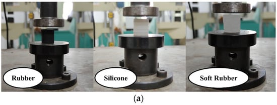
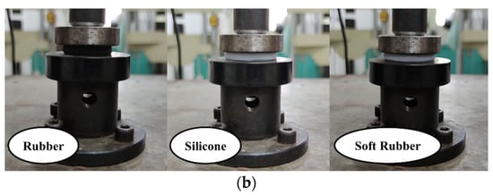
Figure 1.
Uniaxial compression test: (a) before compression; (b) after Compression.
The compression test of the sample adopts the method of GB/T7757-2009. The corresponding stress–strain curve is obtained by collecting the compression load–displacement curve of the sample and the stress is calculated by the load and the cross-sectional area of the test. The high-frequency dynamic force sensor and data acquisition system are used to record the load signal acting on the sample and the displacement information of the actuating cylinder recorded by the system is used to measure the deformation of the sample, by processing the recorded load information and displacement information. In the test, at room temperature, the tester applied vertical compression displacement at a moving speed of 10 mm/min and stopped loading when the displacement reached 175 mm. This is repeated and continuously loaded and unloaded five times; the first two times can be regarded as the adjustment of the experimental machine and the average value of three groups of experimental compression load–deformation data is taken as the final experimental value, as shown in Figure 2.
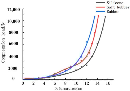
Figure 2.
Fitting curve of compression load–displacement.
According to the obtained compression load–displacement curve, the corresponding nominal stress, strain and strain rate relationship can be obtained by conversion with the following formula:
where: —nominal compressive stress; —compressive load; A0—initial compression area; d—initial diameter of sample; l0—initial height; —compression.
The experimental data obtained are processed by Origin and the results are shown in Figure 3 and Figure 4. According to Figure 3, the Mooney–Rivilin9 model has the highest global correlation coefficient, so the Mooney–Rivilin9 model is selected. According to the independent correlation coefficient in Figure 4, it can be seen that the performance of silica gel under Mooney–Rivilin9 model is the best and the corresponding parameter results are as follows:
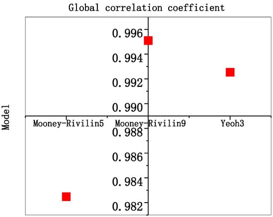
Figure 3.
Global correlation coefficient fitting diagram.
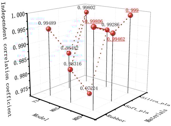
Figure 4.
Fitting diagram of independent correlation coefficient.
C10 = 2.87344; C01 = −2.87331; C20 = −1.22702;
C11 = −0.876372; C02 = 3.42126; C30 = 4.87162;
C21 = 2.2357; C12 = −3.11527; C03 = −12.4457
The fitting equations are as follows: 4–6 and according to the corresponding parameters of each model, the stress–strain relationship is shown in Figure 5.
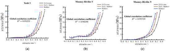
Figure 5.
Stress–strain fitting curves of three models: (a) Yeoh3; (b) Mooney–Rivilin5; (c) Mooney–Rivilin9.
Because the stress–strain curve is the constitutive relation reflecting the inherent mechanical behavior of materials, the calculated stress–strain curves of different samples of rubber, soft rubber and silica gel have good consistency. Combining the independent correlation coefficient with the global correlation coefficient, it can be seen that the Mooney–Rivilin9 model has the best fitting effect. Therefore, the calculated data are averaged and reflected in the stress–strain curves of three materials as shown in Figure 5. As can be seen from Figure 5c, under the same strain, the compressive stress of silica gel is smaller than that of soft rubber and rubber and its softness is better in the compressed environment.
Combined with the comparison of the three materials before and after compression as shown in Figure 6, silica gel not only has the best softness, but also has the best resilience. Therefore, the material of the suction cup in this study is silica gel.
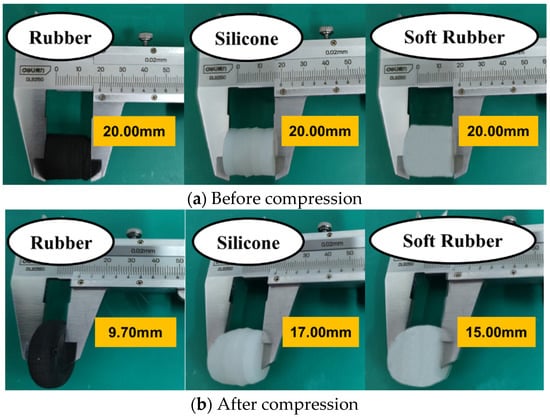
Figure 6.
Uniaxial compression result: (a) before compression; (b) after Compression.
2.1.3. Friction Test and Result Discussion
Silica gel was selected as the sucker preparation material by the simulation test of sucker contact deformation. In order to obtain the subsequent calculation parameters, the friction coefficient measurement test between silica gel and Fuji apple surface is designed (Figure 7) as follows:
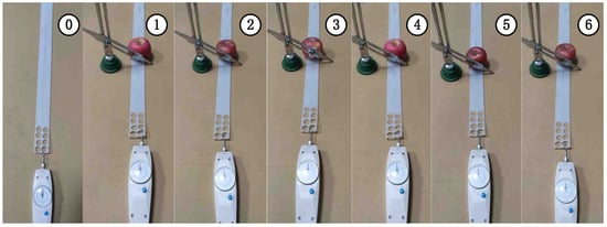
Figure 7.
Friction test between suction cup silica gel material and Fuji apple surface.
The steps are as follows: Cut the silica gel into 500 mm × 50 mm strips with a thickness of 10 mm and spread them on the experimental platform. (1) Drag the sample to slide on the experimental platform with a tension meter, record the number of the tension meter in Table 2 at no load, obtain the sliding dynamic friction force of the sample on the experimental platform and repeat the test six times; (2) prepare five Fuji apples for experiment, label the experimental apples and measure their weights. Put the apple on the surface of the silica gel sample and place a baffle in the middle and upper part of the apple to prevent the apple from following the movement of the silica gel sample. When ready, drag the silica gel sample to slide on the experimental platform with a tension meter and record the number of the tension meter in Table 2 to obtain the total sliding friction of the silica gel sample on the apple surface and the experimental platform. Repeat the experiment six times.
Table 2.
Friction test of suction cup silicone material and Fuji apple surface.
According to the formula
The friction coefficient of silica gel sample on apple surface is 0.83.
2.2. Analysis of Apple-Growth Characteristics
2.2.1. Apple Pose Classification
Seventy-five apple trees were randomly selected and the number of pickable apples, Class A apples (the angle between the fruit pedicel–calyx axis and the ground is between 60° and 90°), Class B apples (the angle between the fruit pedicel–calyx axis and the ground is between 30° and 60°) and Class C apples (the angle between the fruit pedicel–calyx axis and the ground is between 0° and 30°) on each tree were counted, as shown in Figure 8. The statistics showed that 79.54% of the pickable apples were category A, 14.41% of the pickable apples were category B and 5.54% of the pickable apples were category C. The picking tests were conducted on these three categories of apples separately in the experiment.
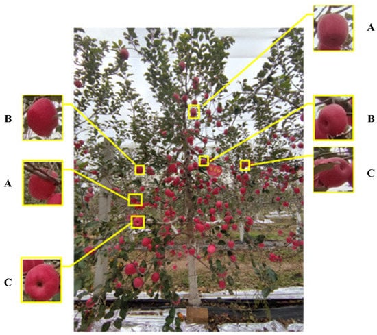
Figure 8.
Classification of apple growth posture: A represents calss A; B represents class B; C represents class C.
2.2.2. Analysis of Apple Characteristics
Due to the different shapes of apples in all directions, the requirements for end effectors are also different. In order to determine the structural parameters of the picker, the following assumptions are made for the apple:
- (1)
- Simplify the apple handle into a straight line;
- (2)
- Apple is in the shape of central axis symmetry and its central axis of symmetry is the straight line where the apple handle is located (as shown in Figure 9).
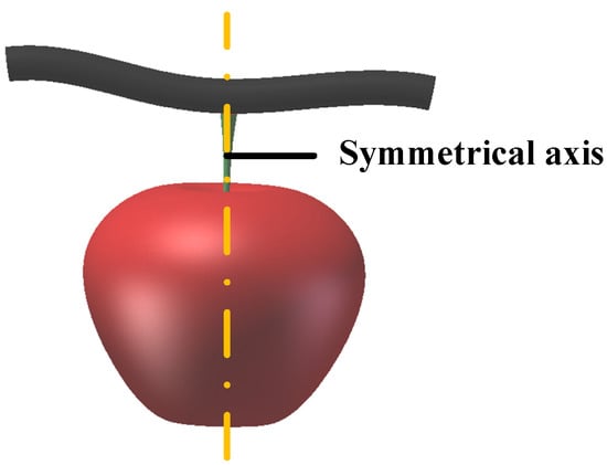 Figure 9. Apple three-dimensional model map.
The conic curve can fit the shape of apple and then the apple can be fitted by the second-order equation modeling analysis and five representative points are selected on the front view of apple. Read out the values of five coordinates in AdobePhotoshop (2020, Adobe Systems Software Ireland Ltd, California, USA) and write a program in MATLABR2014b (MathWorks.Inc, Natick, MA, USA) to fit the apple conic of five points, as shown in Figure 10.
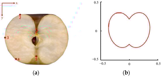
Figure 10.
Apple conic fitting: (a) five representative points are selected on the front view of apple; (b) fit the apple conic of five points.
As the waist curvature of apples with different sizes is different, it will not affect the operation of the picker with this structure, so the growth posture of apples in this section is only analyzed for the curvature of the shoulders and bottom of apples, as shown in Figure 11.
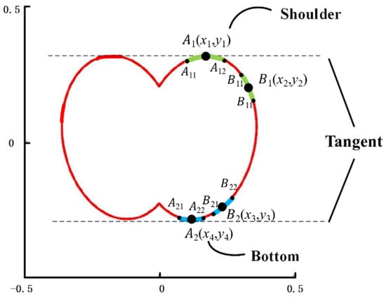
Figure 11.
Apple shoulder and bottom schematic.
Given the curvature formula in two dimensions, its scalar form is:
The method of determining the curvature of unknown curve generally takes the curvature of conic determined by three points as the estimated curvature, as shown in Figure 12, where the curvature at the point is the curvature estimation of the curve determined by these three points.
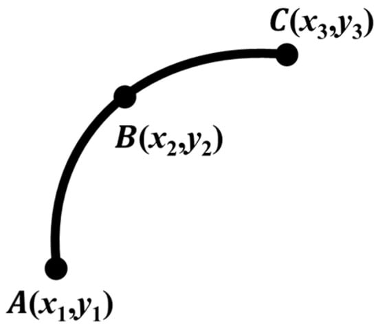
Figure 12.
Three-point determination curve.
The parametric equation expression of the curve is:
The curvature of the curve obtained is:
Through the numpy library in python, the estimated curvatures of the shoulders and bottoms of apples can be visualized, as shown in Figure 13 and Figure 14.
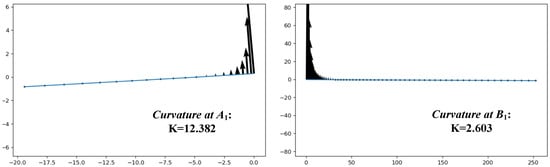
Figure 13.
Apple shoulder curvature.
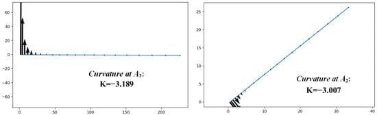
Figure 14.
Apple bottom curvature.
According to the above statistics and analysis results, pickers should adapt to most deflection angles, while effectively picking most graspable apples [26]. In Section 2.3, the structure design of the picker and the optimization of the sucker are analyzed, respectively.
2.3. Design of Air-Suction Octopus Biomimetic Mechanical Hand
2.3.1. Selection and Optimization of Suction Cups
According to the adsorption function and application occasions, the new suction cups currently in use are mainly divided into four types: flat type, bellows type, elliptical type and honeycomb type [27], as shown in Table 3 and Figure 15.
Table 3.
Types and applicable occasions of suction cups.
Figure 15.
Suction cup type: (a) flat suction cup; (b) bellows suction cup; (c) oval suction cup; (d) honeycomb suction cup.
Under the working condition of picking apples, the surface of apples is vulnerable, which requires a certain buffer during the contact between the sucker and apples. At the same time, the growth posture of apples is different and most of them have a certain inclination angle. Comparing all kinds of suction cups mentioned above, the corrugated suction cup is the most suitable for apple sucking, so the subsequent modification design and optimization are carried out based on the corrugated suction cup.
The suction cups used in this research use the atmospheric pressure difference between the inside and outside of the suction cups to suck the workpiece tightly [28]. As shown in Figure 16, when working, the air in the suction cups is quickly pumped out by the vacuum device, so that the pressure inside the suction cups is less than the standard atmospheric pressure and a pressure will be generated under the action of a standard atmospheric pressure, so that the suction cups are firmly adsorbed on the adsorption surface. The higher the vacuum degree in the suction cup [29], the more secure the suction cup is.
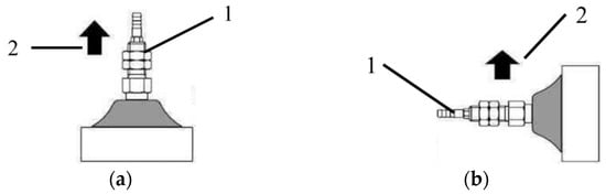
Figure 16.
Two suction modes of suction cups: (a) horizontal suction; (b) vertical suction, where 1: suction cups; 2: direction of suction cup movement.
In this study, the labor-saving picking mode of “rotating-pulling” is adopted and the breaking process of apple handle mainly depends on the multi-directional friction force generated by the adsorption force. Therefore, to ensure the stability of the picking process, the adsorption force, friction force generated by the suction cup and the breaking force of apple handle must satisfy the following relationship [30]:
where: F is the adsorption force exerted by the picker on the apple, N; f is the friction force, N; μ is the friction coefficient; Fn is the breaking force of fruit stalk, N. The adsorption force provided by picking mechanical hand should satisfy the following relationship:
where: Pa is absolute pressure (absolute vacuum value of vacuum pump), kPa; S is the effective area of sucker, mm2; G is the apple gravity, N.
It is known that the breaking force of apple handle is 2–5 N, while the minimum force required for picking apples in the “rotating-pulling” labor-saving picking mode is 10.33 N and the average weight of apples used is 330 g g. According to the 2.1.2.2 test, the friction coefficient between apples and silica gel μ is 0.83. A micro vacuum pump with a vacuum degree of −60 kPa and a rated power of 24 W was selected to ensure enough breaking force for thousands of miles.
According to the above conditions, the suction cup is optimized. First, calculate the basic size of the suction cup design from the suction value required during work:
In the formula: fs: safety factor. The suction force is less than 1/4 when hanging horizontally and less than 1/8 when hanging vertically, as shown in Figure 16.
From the survey, the maximum diameter of ripe apples in the orchard is generally 55–95 mm and the mass is generally 0.1–0.25 kg. Considering that there is acceleration and deceleration movement in the suction cup suction process, the mass of apples is 0.3 kg for calculation here. The designed sucking mode is apple-picking mechanical hand fixed at the end of the robot arm; the end of the robot arm moves horizontally, which corresponds to the vertical sucking mode of the suction cup, so the safety factor is chosen as 1/10 (less than 1/8). From Formula (5), it can be deduced that
where: D is the diameter of suction cup, mm; n is the number of suction cups, pcs.
Therefore, when the number of suction cups n is taken as 3, the diameter of suction cups can be calculated as D = 12.16 mm, so the diameter of designed suction cups is greater than 12.16 mm, then theoretically it can finish sucking and keeping the apple without dropping. In order to ensure the stability of movement, the diameter of suction cups is determined as 15 mm, 20 mm and 25 mm, which is used as the basis for subsequent design.
2.3.2. Suction Cup Biomimetic Layout Structure Design and Optimization
- (1)
- The number of suction cups design
The design of the suction cup layout structure is shown in Figure 17.
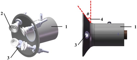
Figure 17.
Mechanical hand: 1. mechanical hand; 2. suction cups; 3 mounting holes; 4. suction cup installation angle.
Based on the apple-growth posture classification, the picking mechanical hand should be able to fully adsorb and pick stably for apples in each growth posture. The authors of [23] investigated whether an angle of 60°–120° between the two fingers in contact with the apple shoulder in the horizontal picking mode can meet the requirements of grip stability when three fingers are picked. Therefore, when the number of suction cups n = 3, the angle between all three suction cups is 120°; when the number of suction cups n = 4, the angle between all four suction cups is 90°; when the number of suction cups n = 5, the angle between all four suction cups is 72°, as shown in Figure 18.
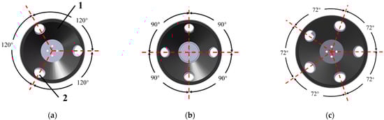
Figure 18.
Three suction cup layout designs: (a) 120° suction cup layout; (b) 90° suction cup layout; (c) 72° suction cup layout, where 1: mechanical hand; 2: mounting holes.
- (2)
- Suction cup layout structure inclination design
In order to make the designed suction cup layout structure universal, according to the assumptions and solution space in Section 2.2, the corresponding size suction cup layout structures are designed for the shoulder and bottom of the apple with 85 mm diameter, as shown in Figure 19.
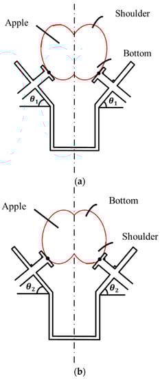
Figure 19.
Three suction cup layout designs: (a) suction cup layout structure for the bottom; (b) suction cup layout structure for the shoulder, where 1: mechanical hand; 2: mounting holes.
According to Section 2.2, we can get the curvature range of the apple shoulder as (2.603, 12.382) and the curvature range of the bottom as (−3.189,−3.007), as shown in Figure 10 and we can also get the tangent equation of at A1, the tangent equation of at B1, the tangent equation of at A2 and the tangent equation of at B2, respectively.
As can be seen from Figure 19 and Figure 20, the inclined plane, suction cup plane and contact point tangent are parallel, so the shoulder inclination , the bottom inclination , so the suction cup layout structure inclination . To ensure the stability of the picking operation, determine the inclination for 30 °, 27 °, 24 ° three, as a basis for subsequent design.
2.4. Control System
2.4.1. Control System of Mechanical Hand
When the target ball fruit is located in the picking range, the controller will issue control instructions to drive the robot to grab the ball fruit through the electromagnetic proportional valve in the pneumatic system to adjust the pressure of the gas passed into each suction cup and use the electromagnetic reversing valve connected to the proportional valve to control the rotary direction of the gas in the gas pipe to pick the apple. The diagram of the manipulator control system is shown in Figure 20.

Figure 20.
Mechanical hand control schematic.
2.4.2. Control System of Apple-Picking Robot
Our aim was to realize the coherent picking of apple-picking robots, i.e., to complete the key link of “identification-picking-fruit release” for coherent picking. To refine and strengthen the logic of these four key steps, the overall process is as follows.
Steps 1, 2 and 3: The robot arm runs to the initial position, which needs to be set in advance. The model sets the initial position on the side of the fruit collection box for two reasons: first, to prevent the robot arm from blocking the camera in eye-to-hand mode; second, it can quickly return to the initial position after releasing the fruit, which shortens the time of fruit-to-fruit connection and improves the overall picking efficiency. The vision system module receives coordinate information of the detected apples.
Steps 4 and 5: After the end of the robotic arm runs to the apple target, the air pump starts to work, generating negative pressure and executing the rotary cross-pull picking mode, i.e., the end joint rotates while the Y direction translates to the fruit release position.
Steps 6 and 7: The end of the robotic arm moves to the fruit release position and opens the solenoid valve and proportional valve to make the gas flow in reverse. Go to step 1 and repeat the process.
Flowcharting the above steps, the apple-picking robot operation flow is shown in Figure 21.
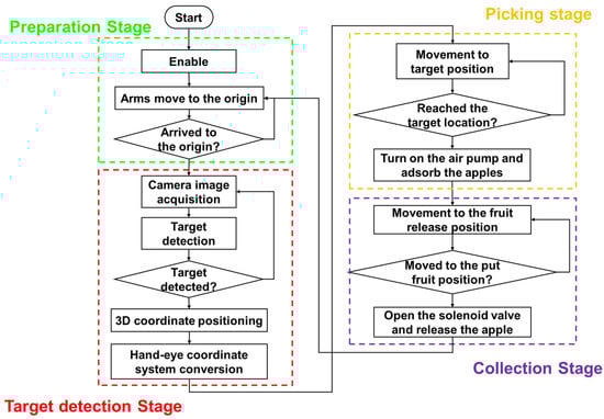
Figure 21.
A flowchart of the harvesting robotic system.
The use of SoftMotion model for picking control strategy design has three advantages: first, the steps are modular, the logic is clear and the computing speed is fast, which not only improves the development efficiency, but also makes it easier for secondary development; second, after the strategy design is completed, before generating the code to deploy the hardware, the operation can be monitored in real time during software-in-the-loop and hardware-in-the-loop simulation and if the operation fails, it can be quickly located to the bug module. The control system hardware module is shown in Figure 22.
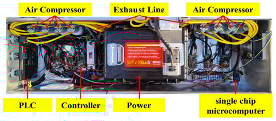
Figure 22.
Control system hardware module.
2.5. Static Simulation and Structural Optimization of Air-Absorbing Biomimetic Mechanical Hand
2.5.1. Simulation of Suction Effect of Suction Cups of Different Sizes
With different sizes of suction cups, suction power varies greatly and the larger the diameter of the suction cup, the greater the suction power. However, the surface of apple is irregularly curved; the larger the diameter of suction cup, the less easy to form a confined space on the surface of apple, which increases the difficulty of suction. In the actual working process, the sucker touches the surface of the apple and if a vacuum cannot be formed, the apple will continue to be pushed and the apple will rotate around the stalk at a certain angle, at which time the stalk will generate a force in the horizontal direction, compressing the contact surface of the apple and the sucker and facilitating the suction. Therefore, for the designed suction cups of 15 mm, 20 mm and 25 mm diameters, this section determines the suitable pushing angle of apple for each suction cup size through simulation test.
Import the geometric model separately in workbench, enter ANSYS Mechanical Enterprise, carry out automatic meshing, encrypt the mesh of contact surface to 0.5 mm, set the top surface of fruit stalk as fixed support, add 2 N support force on the top surface of suction cup and add -X direction displacement, set the time step, after the suction cup touches the upper surface of the disc, add −20 KPa static pressure on the inner Add −20 KPa static pressure on the surface and continuously adjust the displacement of the suction cup in -X direction by observing the suction cup fitting situation until the suction cup is fully fitted with the apple surface, add the rotation probe at the lower vertex of the apple surface and find the rotation angle of the apple around Y axis (Figure 23).
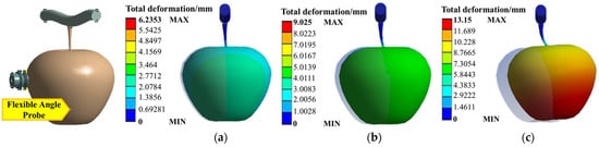
Figure 23.
Three suction cup layout designs: (a) 120° suction cup layout; (b) 90° suction cup layout; (c) 72° suction cup layout.
2.5.2. Simulation of Contact Stress between Suction Cup and Apple under Different Vacuum Degrees
From Equation 14, it can be seen that the vacuum degree has a great influence on the suction force of the suction cup; the larger the vacuum degree, the greater the suction force of the suction cup and the more stable the suction. However, too much vacuum leads to too much suction force and it is easy to make the contact stress between suction cup and apple surface greater than the damage limit stress of Fuji apple, so the simulation test is designed to explore the most suitable vacuum threshold range without damaging the apple.
Import the geometric model in workbench, enter ANSYS Mechanical Enterprise, perform automatic meshing, encrypt the mesh of contact surface to 0.5 mm, set the bottom surface of the disc as fixed support, add 2 N support force on the top surface of the suction cup and add -Z direction displacement, set the time step, after the suction cup touches the top surface of the disc, the inner surface of the suction cup. Add the static pressure between −60 KPa, −70 KPa, −80 KPa and −90 KPa, respectively, and add the stress probe on the surface of the apple for solution (Figure 24).
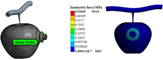
Figure 24.
Contact stress under the apple surface at different vacuum levels.
As the suction cup touches the apple surface and a vacuum gas chamber is formed, the contact stress increases and stabilizes to a slightly smaller value after reaching the maximum stress. When the vacuum level is set to −60 KPa, the maximum stress on the apple surface is 0.22 MPa; when the vacuum level is set to −70 KPa, the maximum stress on the apple surface is 0.22 MPa; when the vacuum level is set to −80 KPa, the maximum stress on the apple surface is 0.22 MPa; when the vacuum level is set to −90 KPa, the maximum stress on the apple surface is 0.22 MPa.
When the suction cup vacuum is −90 KPa, the peak stress on the apple surface is 0.323 MPa, which is greater than 0.31 MPa and when the suction cup vacuum is −80 KPa, the peak stress on the apple surface is 0.286 MPa, which is less than 0.31 MPa, so in the subsequent picking scenario, −80 KPa is used as the rated vacuum level.
3. Results
3.1. Adsorption Test
3.1.1. Single Suction Cup Test
For the suction cup, as a key component in the manipulator, shown by the hydrostatic experimental system in Figure 25, the characteristics of the suction cup and the manipulator were tested, i.e., whether the apple can be adsorbed and whether it will cause damage to the apple.
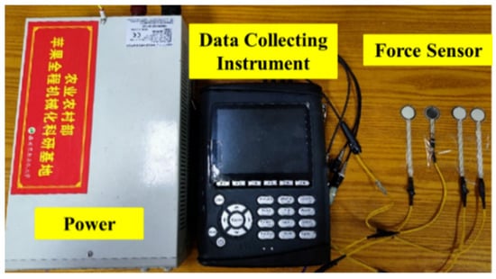
Figure 25.
Robotic hydrostatic experiment system.
The pressure sensor data were collected and analyzed to obtain the change in force generated by the suction cups during the process of apple adsorption. The AB segment corresponds to Figure 26a, which is the pre-tensioning force application stage; the B point corresponds to Figure 26b, which is the state when it first touches the apple; the CD segment corresponds to Figure 26c, which is the tugging and pulling stage after adsorbing the apple; and the DE segment corresponds to Figure 26d,e, which is the releasing stage of the apple.
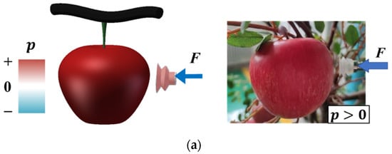
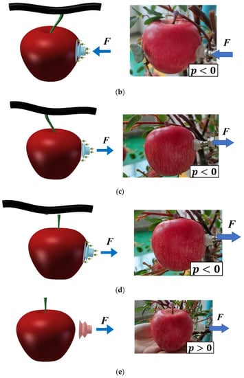
Figure 26.
Sucking process of the suction cup on the apple surface. When the picking mechanical hand picks the apple, the suction cups first touch the apple surface completely with a preload force F (as in (a)). When the negative pressure is generated by the suction cup through the air pump, the negative pressure difference pulls the suction cup toward the apple and pushes the apple with the preload force so that it completely contacts the apple surface (as in (b)). Before the edge of the inner cavity of the suction cup completely touches the surface of the apple (i.e., before it is sealed), the difference between the inner and outer pressure is 0. When the picking mechanical hand retracts, the inner surface of the suction cup pulls the apple with the suction force generated by the negative pressure and the picking force F (as in (c)). At the same time, the static friction between the inner wall of the suction cup and the apple causes the fruit handle to break, thus, achieving the purpose of apple picking (as in (d)). When the apples are released, the air pump is turned off and the pressure difference between the inner surface of the sucker and its crater and the apples is 0. The apples fall off naturally (as in (e)).
The same apple was picked by the above five steps using three sizes of suction cups, 15 mm, 20 mm and 25 mm, respectively, as shown in Figure 27.
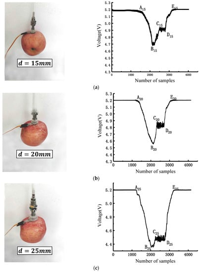
Figure 27.
Single suction cup adsorption force experiment and results: (a) suction cup diameter d = 15 mm; (b) suction cup diameter d = 20 mm; (c) suction cup diameter d = 25 mm.
The test showed that all three sizes of suction cups could successfully complete the picking operation without causing damage to the apples and the browning rate was 0 for one week; meanwhile, the curve analysis generated by comparing the three sizes of suction cups in the process of apple adsorption found that the contact force and adsorption force of 25 mm suction cups were greater at the same time; that is, 25 mm size suction cups should be a better choice.
3.1.2. Mechanical Hand Test
Using a picking mechanical hand for apples with diameters ranging from 60 to 90 cm, which are commonly found in the current market, the picking mechanical hand was tested on seven different sizes of apples at 5 cm intervals, which could meet the requirements of sucking apples without dropping them, as shown in Figure 28.
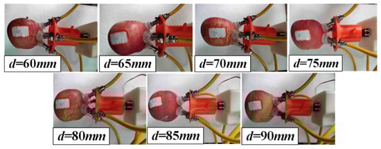
Figure 28.
End-effector testing on different apple sizes.
3.2. Dynamic Stability Test
When the mechanical hand grips the fruit, the fruit is rotated by hand to simulate and decompose the phenomenon of sliding between the fruit and the picking mechanical hand during the picking process, as shown in Figure 29. By collecting and analyzing the pressure sensor data, we obtain the discriminatory basis of the occurrence moment of the relative slippage of the fruit surface relative to the picking mechanical hand. According to the working principle of the thin-film pressure transducer, the upper and lower surfaces of the sensor producing relative displacement will have an impact on the internal carbon particle arrangement, thus, affecting the sensor signal output. The relationship between the movement speed, acceleration and smoothness of the fruit relative to the picking mechanical hand on the change in the signal of the thin-film pressure sensor can be used as a subsequent in-depth research process. In the experiment, the air-pressure-regulating valve was manually operated to control the air pressure change and the pressure sensor data were collected in real time. Four pressure sensors were arranged on the surface of the apple and the data change was generated when the picking mechanical hand touched the sensor and the sampling frequency was set to 180 kHz by the program.
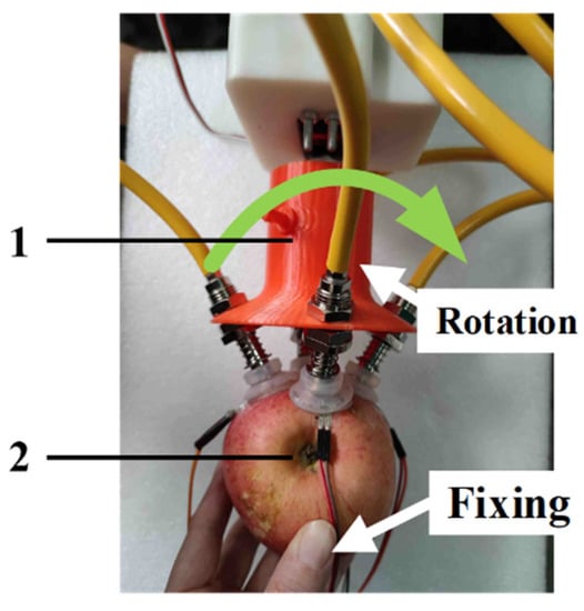
Figure 29.
Dynamic stability test experiment: 1: mechanical hand; 2: apple.
The time domain signals of the four groups of pressure sensors in the case of rotation were obtained, as shown in Figure 30a,b. Before the fruit was pulled and slid or rotated, the digital signals of the four pressure sensors were maintained at a certain value, but the values of the four sensors were different because the piezoresistive sensors were sensitive to the pressure position and the surface shape of the apple was not completely symmetrical, resulting in different pressure positions and sizes of the sensors. When the fruit encounters pulling slip and rotating slip, the four groups of pressure sensor readings produce large fluctuations, but the overall trend is decreasing and, in the case of rotation, there are multiple fluctuating positions because the occurrence of slip is not continuous. The time domain signal adjacent to the two points of the difference can be obtained adjacent to the data difference graph, from which the maximum location of the increase generated can be clearly seen. The dynamic mean value is the sum of the acquired signals solved for the mean value in real time during signal acquisition and its formula is
where Dysum(x) is the dynamic synthesis of the data; x is the amount of data received so far; n(i) is the data array and i is the serial number; lengthdata is the total length of the data; and Dyavg(x) is the dynamic mean value of x data, as shown in Figure 26c.
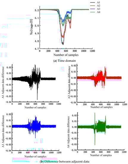
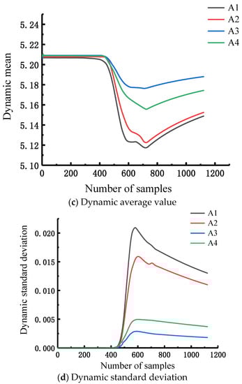
Figure 30.
Analysis of pressure sensor dynamic data when rotation generates slippage.
The dynamic standard deviation SD is calculated as follows:
It is obvious from the dynamic standard deviation curve that the dynamic standard deviation increases significantly when the digital signal of the pressure sensor decreases and, in the case of rotation, both sensors 1 and 2 produce fluctuating data and the “step” type of growth can be seen in the dynamic standard deviation curve, as shown in Figure 30d.
3.3. Apple-Picking Test
For the subsequent testing of the end effects of apple picking by the mechanical hand, 80–90 Fuji fruits were selected and the real apples were hung on the model fruit tree for the picking test to determine the best ratio of the actuator and to verify the picking effect at the same time. In order to better simulate the force between the fruit stalk and the branch trunk of the fruit tree, a 30 mm outer diameter of 0.56 mm was used.
Different materials of suction cups, contact area between suction cups and apples, number of suction cups, apple size and picking mode were important indicators affecting the picking effect. Among them, the material of suction cups was determined by pre-experiments; the cross diameter of red Fuji apples harvested at maturity was mainly concentrated between 80 and 90 mm, accounting for an average probability of 97.7%. By evaluating the success rate of apple picking and the degree of apple surface damage, it is proposed to determine the best ratio of the number and size of suction cups most suitable for the apple-picking operation.
Based on the above classification, apples were fixed at arbitrarily selected locations and picking tests were conducted to evaluate the picking success rate and the degree of damage to the surface of apples. The actuator bodies with three, four and five suction cups were selected and suction cups with installation angles = 24°, = 27° and = 30° and diameters d = 15 mm, d = 20 mm and d = 25 mm, respectively, were tested on apples of the same size (apple diameter between 80 and 90 cm). In total, 29 sets of tests were conducted with 25 samples in each set, as shown in Figure 31 and Figure 32.
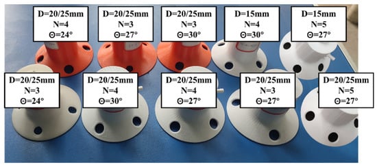
Figure 31.
Part of the suction cup layout structure.
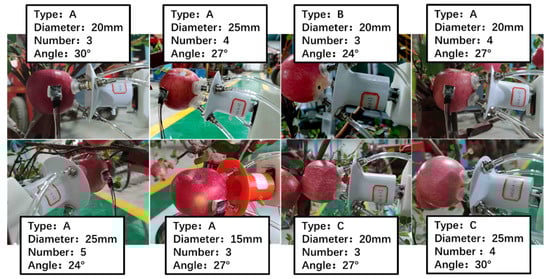
Figure 32.
Part of the test process pictures.
For each group of tests, after the actuator picked 25 samples, the picking success rate and apple damage were recorded, respectively; that is, a group of picking tests was completed, as shown in Table 4 for some experimental results. Finally, the optimal ratio of actuator settings was selected according to the picking success rate and apple damage rate. The success rate is shown in Equation (24).
where: the is the total number of samples in a set of trials, i.e., 25 apples; the is the number of successful apples picked in a set of samples.
Table 4.
Results of orthogonal test for picking mechanical hand-picking operation.
In other words, when the number of suction cups is four, the size of suction cups is 25 cm and the angle of suction cup arrangement is 27°; the picking success rate is 100%, 76% and 68% for three different apple-growth postures of A, B and C, respectively, so this is the best ratio.
3.4. Apple-Picking Test Utilizing Harvesting Robot
The Sony FDR-AX45 camera was used to film the picking process of each group of tests and the time of the robot arm going to the approaching point, the grasp time, the picking mode time and the time of fruit release to the fruit collection box were recorded by reading the seconds.
The time statistics for the three processes of “Reach, Pick and Release” are shown in Figure 33. The average time for the three processes of Reach–Pick–Release was 8.05 s, with Reach taking the longest time, about 9.8 s. This is due to the fact that the robot has greatly extended the operating range and the starting position is farther away from the apple target, so the process of going to the picking point takes more time; the Pick stage takes the shortest time, about 0.8 s, to reach the apple. The duration of the Pick stage is the shortest, about 0.8 s. After reaching the apple-picking point, it only needs to adsorb the apples and does not consume much time; the duration of the Release phase is about 5.5 s.
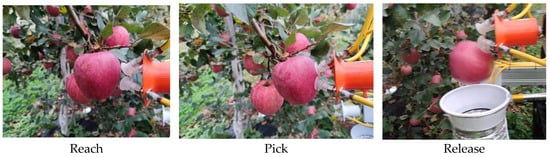
Figure 33.
Picking process.
In terms of the Reach stage during the field test, the apple-harvesting robot can pick fruit with a distance between the fruit and suction cups less than 82 cm.
4. Discussion
4.1. Response Surface Analysis and Parameter Optimization of Apple-Picking Test
Response surface was used to analyze the correlation between dependent and independent variables. The best combination of the optimal picking mechanical hand was obtained by fitting the factors as a function of response values using a quadratic multiple-distant regression equation and this experiment used a polynomial of the second-order Taylor series, the quadratic response surface model, to represent the function, as shown in Equation (25).
where, y—response value (dependent variable); β0—constant coefficient model; βi, βii—linear and quadratic term coefficients; βij—interaction term coefficients; xi, xj—coded values (independent variables).
The expectation function (D(x)) is used to evaluate the degree of expectation of the independent variables at the selected level and, thus, to perform multiple-response optimization. The expectation function can be expressed as follows.
where yi (i = 1, 2, …, n) is the dependent variable and n is the number of dependent variables.
Different materials of suction cups, contact area between suction cups and apples, number of suction cups, apple size and picking mode were important indicators affecting the picking effect. Among them, the material of suction cups was determined by pre-experiments; the horizontal diameter of red Fuji apples harvested at maturity was mainly concentrated between 80 and 90 mm, accounting for an average probability of 97.7%. By evaluating the success rate of apple picking, it is proposed to determine the best ratio of the number and size of suction cups most suitable for the apple-picking operation.
A four-factor, three-level Box–Behnken test with the number of suction cups, suction cup diameter, suction cup installation angle and apple-growth posture as factors was designed using Design-Expert 8.0 (Stat-Ease, Inc. Minnesota, USA) and the test codes are shown in Table 5. In total, 29 sets of trials with 25 samples per group were conducted with picking success as the response value, as shown in Figure 33 and Figure 34. For each group of trials, after 25 samples were picked by the actuator, the picking success rate and apple damage were recorded, respectively; that is, a group of picking trials was completed and the test results are shown in Table 6.
Table 5.
Levels of control factors.
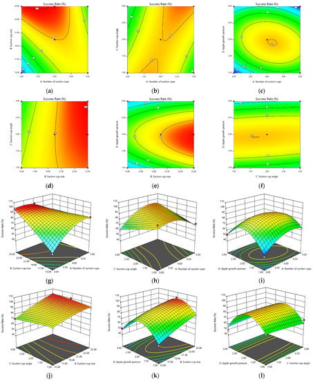
Figure 34.
The interactions between the number of suction cups, suction cup diameter, suction cup angle and apple growth posture: (a–f) 2D contours; (g–l) 3D surface plots.
Table 6.
Experimental design and simulation results of the response.
ANOVA can verify the accuracy of the model. Table 7 shows the ANOVA results for the success rate. The mean square, degrees of freedom (DoF), sum of squares, F-Value and p-Value are the parameters used to check the validity of the model. The accuracy of the parameters is higher for F-Values > 1 and for p-Values less than 0.05, the model is accepted from a statistical point of view.
Table 7.
ANOVA of apple-picking equipment quadratic model responses.
The quadratic regression equation obtained from the regression of apple-picking response values (success rate) is given by the following equation.
Table 7 was used to evaluate the ANOVA results of the quadratic model. The model F-value is 45.00, indicating that the model is significant. The model p-value is less than 0.0001, the model is significant and the p-value is greater than 0.05; the misfit term is not significant. The coefficient of determination (R2), the adjusted coefficient of determination (Adj R2) and the p-value reflect the degree of model fit and the prediction coefficient of determination (Pre R2) indicates the accuracy of the regression model on the predicted results. Among them, X1, X2, X4, X1X2, X1X3, X1X4, X12 and X42 showed significant effects on apple-picking success (p < 0.05), while X3, X2X3, X2X4, X3X4, X22 and X32 had p values greater than 0.05, indicating that these three were non-significant terms. R2 = 0.9783 indicated that the response misfit of the model was only 2.17% of the total 2.17% and the corrected coefficient of determination Adj R2 = 0.9565 also indicates the significance of the model.
The combined effect of each variable when either variable is kept constant at the central level and the other two variables are varied within the optimized level is shown in 2D contours and response 3D surface plots in Figure 34. The effects of number of suckers, sucker diameter, sucker angle and apple-growth posture on the success rate are indicated, respectively. The larger curvature of contours shown in (a), (b), (c) and (e) in Figure 34 indicates that there is a greater interaction between number of suckers and sucker size, number of suckers and sucker angle, number of suckers and apple-growth stance and sucker size and apple-growth stance. The smaller contour curvature shown in (d) and (f) in Figure 34 indicates that there is less interaction between sucker size and sucker angle, sucker angle and apple-growth stance.
According to the quadratic regression (Equation 27) and the response surface plot in Figure 34g–l, the other variables are kept constant and, when the suction cup size is kept at a low level (15–18 mm), the increase in the number of suction cups leads to an increase in the success rate; when the suction cup size keeps increasing (18–25 mm), the increase in the number of suction cups leads to a first increase and then a decrease in the success rate, reaching a peak at the suction cup size of 25 mm and the number of suction cups is four.
When the suction cup angle is kept at a low level (24–27°), the increase in the number of suction cups leads to a first increase and then a decrease in the success rate; when the suction cup angle is continuously increased (27–30°), the increase in the number of suction cups leads to a continuous increase in the success rate.
When the number of suckers was kept at a low level (3–4), the change in apple pose led to a larger rate of change in success rate; when the number of suckers kept increasing (4–5), the change in apple pose led to a gradual decrease in success rate after the first increase and the success rate peaked when the number of suckers was four and the growth pose was 2.
When the suction cup angle is kept at a low level (24–25.5°), the increase in the number of suction cups leads to a gradual increase in the success rate; when the suction cup angle is continuously increased (25.5–30°), the increase in the number of suction cups leads to a significant increase in the success rate, peaking at a suction cup size of 25 mm and a suction cup angle of 30°.
When the sucker size was kept at a low level, the success was first lifted and then decreased as the apple-growth stance increased; when the sucker size kept increasing, the increase in apple-growth stance also led to the success being first lifted and then decreased and peaked at a sucker size of 25 mm and a growth stance of 2.
When the suction cup angle is constant, the increase in apple-growth posture leads to a first increase and then a decrease in success rate. As the suction cup angle increases, the trend of success rate keeps increasing and then decreasing as the apple-growth posture becomes larger.
The Adeq. Precision of 20.0225 in Table 6 indicates that the model has sufficient signal-to-noise ratio, indicating that the model can be used to optimize the parameters. Using the highest success rate as an indicator, the four factors of the picker were optimized and the constraints and prediction results are shown in Table 8 and Table 9.
Table 8.
Optimization conditions.
Table 9.
Comparison of validation test and model prediction results.
The validation test was conducted with four suction cups, suction cup size of 25 mm, suction cup angle of 27.1° and apple-growth attitude of 2 (A), as shown in Figure 29. The success rate was 100% and the relative deviation from the model prediction was 0.184%. The results showed that the combination of four suction cups, 25 mm suction cup size, 27.323° suction cup angle and 2 (A) apple-growth attitude was the optimal combination, with the highest picking success rate in the validation test.
4.2. Apple Damage Issues
Damage to apples is mainly caused by the following three main factors:
- (1)
- Due to the curvature of the contact point between the apple surface and the sucker being too large, there will be a certain few suction cups that do not completely fit the fruit surface; that is, the suction cups do not produce vacuum, reducing the clamping stability, thus, making the pressure feedback signal inaccurate or lost, especially when picking apples in the B and C growth posture, so the phenomenon of not being able to produce vacuum becomes greater;
- (2)
- The suction cups diameter is smaller, so that the contact area between the apple and the sucker is smaller; that is, the same pressure vacuum produces less adsorption force on the apple than the breaking force of the fruit stalk;
- (3)
- Influenced by the fruit stalk and the surrounding fruit, the sucker will separate the sucker and the apple when the sucker is adsorbing the apple, resulting in the sucker in the picking mechanical hand not completely fitting the surface of the fruit and the fruit falls off during the twisting process, causing damage.
In this paper, only a random sample of ripe apples was used to count the clamping effect and the effect of different ripeness was not studied. Therefore, based on the results of picking success rate, direct damage rate and browning rate, it can be seen that the low-loss biomimetic octopus picker developed in this paper has a good nondestructive clamping effect and excellent picking performance.
Meanwhile, in this paper, the damage produced by the above reasons was only roughly judged by observing the surface of the apples at the time of picking and within 7 days, and the impact of the manipulator on the apples was judged without carefully and meticulously analyzing the deformation inside the apple tissues, which can be combined with image analysis [31], LabView [32]. We should, further, pay more attention to the damage of the apple, especially tissue damaging in every automatic apple-harvesting section to achieve the goal of continuously reducing apple damage.
4.3. Application Problems of Apple-Picking Hands
This study further reduces the damage to apples during apple picking by bringing the suction cups into direct contact with the apples. Since this apple-picking mechanical hand can perform nondestructive picking operations as long as it touches a part of the apple surface, it can be successfully equipped on the apple-picking robot (shown in Figure 35), completing apple picking in an orchard for the cases due to branch shading, branches next to apples, apples against apples, etc. This apple-picking mechanical hand effectively solved the problem of picking failure due to the close distance between apples and others during three-finger picking.
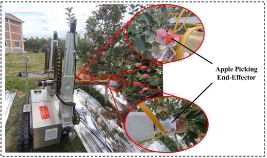
Figure 35.
Apple-picking robot equipped with the designed mechanical hand.
Utilizing the real-time apple target detection method based on improved YOLOv5 network and Intel RealSense D435 Depth Camera to detect the pose of apples and classify apples into graspable and ungraspable apples in an apple tree image, the apple-picking robot provides real-time accurate detection for the pose of pickable apples towards the picking robot. On the basis of the recognition result, we obtain the coordinates of the picking point in the camera coordinate system based on the conversion relationship between the physical coordinate system and the camera coordinate system, combined with the distance information of the depth map and acquire the relationship matrix between the picking hand and the depth camera through the “Eye-to-hand” system calibration algorithm and experiment, which translates the detection result of apple pose grasp pose for the robot.
However, during the experiment, some problems were found, such as (1) when the mechanical hand coped with the situation that the leaves blocked the apples, the suction cups were adsorbed on the surface of the leaves and could not reach the surface of the apples, which affected the picking success rate; (2) the movement direction of the mechanical hand was the same as the movement direction of the last joint of the robot arm, which led to the lack of flexibility in the picking operation.
For the case of overlapping apple fruits with leaves, we will install an air-blowing device on the mechanical hand: when the mechanical hand approaches the apple covered by leaves, the air-blowing device starts to work and blows away the leaves on the surface of the apple and then the robot carries out the picking operation. For the case of the contact of two apples on the crown of a tree, the control system will send instructions to the robot when the camera detects that the distance between two apples is less than or equal to the diameter of one apple: pick the one closer to the robot first and then pick the one slightly farther away and the robot will achieve successful harvest of two apples on the crown of a tree via this strategy.
Therefore, it is hoped that a more successful and flexible apple-picking mechanical hand can be developed in subsequent research.
5. Conclusions
According to the principle of bionics and simulating the mechanism of octopus predation, an air-suction biomimetic nondestructive apple-picking mechanical hand was designed. The picking mechanical hand mainly consists of four suction cups with corresponding suction cup layout structure; according to the growth characteristics of apples, the key parameter range of the picking mechanical hand is determined and finite element analysis is conducted to further determine the rationality of the picking mechanical hand structure. According to the above results, the picker is assembled and the relevant performance test is carried out.
According to the adsorption force test, the state of the suction cups during the picking operation can be determined and the picking mechanical hand can pick apples with a diameter of 60–90 cm; according to the slip test, it can be determined that the slip between the suction cups and apples during the rotation of the picking mechanical hand will not cause the apples to fall.
Based on a prototype air-suction biomimetic nondestructive apple picker and applying it to a picking robot, a four-factor, three-level orthogonal test of apple picking was conducted in a laboratory environment. The laboratory results showed that the number of suction cups was four, the suction cup size was 25 mm and the suction cup angle was 27.323°. The picking success rate was 100% when picking apples with growth attitude A; the picking success rate was 76% when picking apples with growth attitude B; and the picking success rate was 68% when picking apples with growth attitude C, which was the optimal combination. These results show that the picking hand can operate nondestructively and at a low cost to meet the actual operational needs and can solve the current situation that the operation fails due to easy-to-pinch branches and so on during the clamping picking operation.
In the apple-picking robot in this study, the motor models of the corresponding axes of the double arms are the same and the power of the three motors corresponding to one robot arm is 0.75 kw, 0.2 kw and 0.4 kw, the power of the air pump is 0.024 kw and the capacity of the power supply is 8.4 kw. The single fruit picking speed of the robot is 8 s/each and the average single-axis movement time is 5 s when picking a single fruit, so the robot can work continuously for 12.199 h. That is, the apple-picking robot consumes 8.4 kw of electricity for 12.199 h of continuous operation.
We expect to develop apple-picking robots with solar panels so that the robots can operate continuously in the orchard for 24 h, further improving the operational efficiency of the apple-picking robots.
Author Contributions
M.W. and B.Y.: Writing—original draft, Data curation, Resources, Formal analysis. S.Z.: Software, Validation, Investigation, Writing—original draft. P.F.: Resources, Data curation, Writing—review and editing. P.Z. and S.S.: Conceptualization, Supervision, Visualization. F.Y.: Writing—review and editing, Project administration, Funding acquisition. All authors have read and agreed to the published version of the manuscript.
Funding
This research was funded by the Major Science and Technology Project of Shaanxi Province of China (Program No. 2020zdzx03-04-01).
Institutional Review Board Statement
The study in the paper did not involve humans or animals.
Data Availability Statement
Not applicable.
Acknowledgments
We are grateful to Bin Yan and Pengjv Guo for their help with writing format.
Conflicts of Interest
The authors declare no conflict of interest.
References
- Kuta, Ł.; Li, Z.; Stopa, R.; Komarnicki, P.; Słupska, M. The influence of manual harvesting on the quality of picked apples and the Picker’s muscle load. Comput. Electron. Agric. 2020, 175, 105511. [Google Scholar] [CrossRef]
- Zhang, Z.; Igathinathane, C.; Li, J.; Cen, H.; Lu, Y.; Flores, P. Technology progress in mechanical harvest of fresh market apples. Comput. Electron. Agric. 2020, 175, 105606. [Google Scholar] [CrossRef]
- Lingxin, B.; Guangrui, H.; Chengkun, C.; Sugirbay, A.; Chen, J. Experimental and simulation analysis of optimum picking patterns for robotic apple harvesting. Sci. Hortic. 2020, 261, 108937. [Google Scholar] [CrossRef]
- Yunwei, Z.; Dexu, G.; Xiaomin, L.; Guodong, S. Kinematics analysis and experiment on pneumatic flexible fruit and vegetable picking manipulator. Nongye Jixie Xuebao/Trans. Chin. Soc. Agric. Mach. 2019, 508, 31–42. [Google Scholar]
- Xioyang, L.; Dean, Z.; Welkuan, J.; Chengzhi, R.; Wei, J. Segmentation method based on superpiel features for apple harvesting robot. Trans. Chin. Soc. Agric. Mach. 2019, 50, 15–23. [Google Scholar]
- Guoli, L.; Changying, J.; Baoxing, G.; Weiyue, X.; Mang, D. Kinematics analysis and experiment of apple harvesting robot manipulator with multiple end-effectors. Trans. Chin. Soc. Agric. Mach. 2016, 47, 14–21. [Google Scholar] [CrossRef]
- Yubin, M.; Jiafeng, Z. Development of compliant constant-force mechanism for end effector of apple picking robot. Trans. CSAE 2019, 35, 19–25. [Google Scholar]
- Qinchuan, L.; Ting, H.; Chuanyu, W.; Hu, X. Review of end-effectors in fruit and vegetable harvesting robot. Trans. Chin. Soc. Agric. Mach. 2008, 39, 175–179. [Google Scholar]
- Wang, Y.; Hongbin, X.; Mao, Z.; Jitong, M.A.; Bo, L.I.U.; Yu, H.E. Design and experiment of bite-model end-effector for citrus harvesting by simulating with mouth of snake. Trans. Chin. Soc. Agric. Mach. 2018, 49, 54–64. [Google Scholar]
- Wang, Y.; Yang, Y.; Yang, C.; Zhao, H.; Chen, G.; Zhang, Z.; Fu, S.; Zhang, M.; Xu, H. End-effector with a bite mode for harvesting citrus fruit in random stalk orientation environment. Comput. Electron. Agric. 2019, 157, 454–470. [Google Scholar] [CrossRef]
- Zhao, D.A.; Lv, J.; Ji, W.; Zhang, Y.; Chen, Y. Design and control of an apple harvesting robot. Biosyst. Eng. 2011, 110, 112–122. [Google Scholar]
- Wang, G.; Yu, Y.; Feng, Q. Design of end-effector for tomato robotic harvesting. IFAC-Pap. OnLine 2016, 49, 190–193. [Google Scholar] [CrossRef]
- Yan, P.; Yonggan, L.; Yang, Y.; Na, L.; Yi, S. Research progress on application of soft robotic gripper in fruit and vegetable picking. Trans. Chin. Soc. Agric. Eng. 2018, 34, 19–28. [Google Scholar]
- Yi, D.; Wei, J.; Bo, X.; Guangyu, C.; Dean, Z. Parameter self-tuning impedance control for compliance grasp of apple harvesting robot. Trans. CSAE 2019, 35, 257–266. [Google Scholar]
- Glicj, P.; Suresh, S.A.; Ruffatto, D.; Cutkosky, M.; Tolley, M.T.; Parness, A. A soft robotic gripper with gecko-inspired adhesive. IEEE Robot. Autom. Lett. 2018, 3, 903–910. [Google Scholar] [CrossRef]
- Khaled, E.; Niels, L.; Micheal, J. Bending angle prediction and control of soft pneumatic actuators with embedded flex sensors—A data-driven approach. Mechatronics 2018, 50, 234–247. [Google Scholar]
- Xiaomin, L.; Debao, T.; Maozheng, S.; Dexu, G.; Yunwei, Z. Design and experiment on pneumatic fexible gripper for picking globose fruit. Transacions Chin. Soc. Agric. Mach. 2021, 52, 30–43. [Google Scholar]
- Xudong, L.; Luzhong, M. Design of an apple picking actuator based on metamorphic mechanism. Mach. Tools Hydraul. 2017, 45, 14–16. [Google Scholar]
- Eric, B.; Nicholas, R.; John, A.; Mozeika, A.; Steltz, E.; Zakin, M.R.; Lipson, H.; Jaeger, H.M. Universal robotic gripper based on the jamming of granular material. Proc. Natl. Acad. Sci. USA 2010, 107, 18809–18814. [Google Scholar]
- Amend, J.R. A positive pressure universal gripper based on the jamming of granular material. IEEE Trans. Robot. 2012, 28, 341–350. [Google Scholar] [CrossRef]
- Yubin, M.; Jiafeng, Z. Optimization design of compliant constant-force mechanism for apple picking actuator. Comput. Electron. Agric. 2020, 170, 105232. [Google Scholar]
- Tom, S. Apple-Picking Robot Prepares to Compete for Farm Jobs. Available online: https://www.teachnologyreview.com/s/604303/apple-picking-robot-prepares-to-compete-for-farm-jobs/ (accessed on 3 May 2017).
- Fan, P.; Yan, B.; Wang, M.R.; Lei, X.; Liu, Z.; Yang, F. Three-finger grasp planning and experimental analysis of picking patterns for robotic apple harvesting. Comput. Electron. Agric. 2021, 188, 106353. [Google Scholar] [CrossRef]
- Chen, L. The Constitutive Theory of Hyper Nonlinear Elastic Body; National Defence Industry Press: Beijing, China, 2012. [Google Scholar]
- Lili, W. The Determination of Hyperelastic Material Parameters and the Application in the Micropipette Aspiration Experient Model; Taiyuan University of Technology: Taiyuan, China, 2013. [Google Scholar]
- Yan, B.; Fan, P.; Lei, X.; Liu, Z.; Yang, F. A Real-Time Apple Targets Detection Method for Picking Robot Based on Improved YOLOv5. Remote Sens. 2021, 13, 1619. [Google Scholar] [CrossRef]
- Weifu, Z. Bionic Characteristic of Distycus’ Sucking Discs and the Analog Simulation Study on Vacuum Multi-Sucking Discs; Jilin University: Jilin, China, 2006; pp. 3–4. [Google Scholar]
- Lianqiang, B.; Zhongkang, S.; Peng, W. Simulation analysis of internal flow field of vacuum chuck under different leakage conditions. Mech. Eng. 2018, 7, 33–35, 38. [Google Scholar]
- Asbeck, A.T.; Kim, S.; Cutkosky, M.R.; Provancher, W.R.; Lanzetta, M. Scaling Hard Vertical Surfaces with Compliant Micro-spine Arrays. Int. J. Robot. Res. 2006, 25, 1165–1179. [Google Scholar] [CrossRef]
- Xiaolei, D.; Zhongyi, L.; Jingquan, P.; Yimin, Z.; Changjie, Y. Design and experiment of bionic nondestructive handheld suction apple picker. J. China Agric. Univ. 2019, 24, 10–108. [Google Scholar]
- Beyaz, A.; Ozturk, R.; Turker, U. Assessment of mechanical damage on apples with image analysis. Food Agric. Environ. (JFAE) 2010, 8, 476–480. [Google Scholar]
- Beyaz, A. Harvest glove and LabView based mechanical damage determination on apples. Sci. Hortic. 2018, 228, 49–55. [Google Scholar] [CrossRef]
Publisher’s Note: MDPI stays neutral with regard to jurisdictional claims in published maps and institutional affiliations. |
© 2022 by the authors. Licensee MDPI, Basel, Switzerland. This article is an open access article distributed under the terms and conditions of the Creative Commons Attribution (CC BY) license (https://creativecommons.org/licenses/by/4.0/).