Abstract
A vertical variable cavity organic fertilizer and compound fertilizer apparatus were designed according to tobacco farming requirements to overcome issues of unstable fertilizer discharge and blocking in the fertilizer disk of an existing fertilizer apparatus. The structure and working principle of the fertilizer apparatus were described. Combined with the principle of anti-arch and the requirements of fertilizer application, the structure size of the fertilizer apparatus was determined. Using the opening degree and rotational speed of the fertilizer disk as the test factors and the fertilizer rate and variation coefficient of fertilizer application rate as the indices, the EDEM was used to conduct the single factor test and obtain the appropriate rotational speed range. The results indicated that the variation coefficient of the fertilizer uniformity apparatus was 0.96–5.22% under different rotation speeds and fertilizer disk openings, which satisfied design requirements. The orthogonal experiment explored the interaction between rotational speed and the opening. The influence of the opening adjustment on the fertilizer application rate and the coefficient of variation of uniformity were greater than the change in fertilizer disk speed. The bench and field tests aligned with the simulation test. These findings provide a reference and theoretical basis to design a fertilizer apparatus.
1. Introduction
Chemical fertilizers play an important role in increasing crop yield and income; however, the application of large amounts also results in soil compaction and acidification, causing environmental pollution [1]. In recent years, the application of organic fertilizer has become increasingly extensive, as it can improve the physical and chemical properties of soil and topsoil structure, increase crop yield, and realize resource recycling [2,3,4]. Tobacco field planting in northern China conducts tillage prior to tobacco seedling transplanting and ridging, and adding organic and compound fertilizers as base fertilizers aids with fertilization. A commonly used fertilizer machine acts as the fertilizer spreader. The fertilizer spreader can evenly spread fertilizer on the surface, then turn the soil with the plow and rake, and mix it in the soil. The ridging operation completes the preparation work before tobacco transplanting. This method not only has a low fertilizer utilization rate, but also increases the planting cost and labor. Using an integrated operation technology of ridging and fertilization would allow fertilizer to be directly applied to the ridge, which can effectively improve the utilization rate of fertilizer. The existing fertilizer apparatus has associated problems, including poor uniformity of fertilization, unstable operation, and blocking of fertilizer discharge. At the same time, compound and organic fertilizers should be combined for fertilization at a certain proportion to improve fertilization efficiency.
At present, most fertilizer devices studied and designed worldwide include external groove wheel-types, disk-types, and spiral-types, among others [5]. Villette et al. [6,7] established the functional relationship between the velocity of fertilizer particles and horizontal outlet angle, disk shape, and rotational speed, and developed a digital imaging system using machine vision technology to estimate and measure the horizontal outlet angle and velocity components. Coetzee et al. [8] designed a centrifugal disc-type fertilizer sparer and studied the influence of factors such as disk speed, feed speed, and leaf angle on fertilizer spreading. KUHN, a French company, developed a fertilizer machine using a double screw conveyor design that ensured the uniformity and continuity of material throwing, with a strong adaptability for application in a variety of materials. Further, Zha et al. [9] designed a fertilizer applicator, which could adjust the amount of fertilizer by adjusting the opening width of the gear wheel, and designed and analyzed each working parameter. Liu et al. [10,11] designed a fertilizer device for the cavitation fertilization of granular fertilizer. The fertilizer discharging mechanism of the fertilizer device was mainly composed of the stator and rotor of the fertilizer discharging plate. The gap between the stator and the rotor was the fat cavity. The rotor could rotate relative to the stator to adjust the size of the fat cavity. Przywara et al. [12] designed a fertilizer spreading machine, analyzed the influence of functional parameters and operating parameters on the average radius of fertilizer spreading, and analyzed the angular velocity of the disc and the blade configuration. Alameen et al. [13] designed a variable fertilization test bed adjusted by a cylinder, which could adjust the opening and speed of the fertilizer drainer, and exhibited good stability and fertilizer discharging performance. Wang et al. [14,15] designed a deep fertilizer apparatus on the side of a paddy field with an adjustable fertilizer trough size. The device could adjust the cross-section area of a single fertilizer trough by adjusting the position of the top rod in the fertilizer trough to realize the adjustment of the fertilizer application amount. The device demonstrated better fertilization uniformity when compared with a fertilizer discharge device with a straight and chute wheels.
A vertical variable cavity base fertilizer combined application device was designed according to the agronomic requirements of fertilizer application in the tobacco growing area of Xuchang City, Henan Province, China. The reason for fertilizing jams was analyzed through theoretical analysis and calculation to determine the fertilizer disk structure parameters, using a simulation test, bench test, and field test to validate the performance of the device application. We aimed to solve the issues of poor fertilization evenness, instability of running, and distributing congestion, while achieving precise fertilization and improving the utilization rate of the fertilizer. Our findings provide technical reference and theoretical support for the design and optimization of fertilization plants.
2. Overall Structure and Working Principle
A diagram of the ridging fertilizer applicator structure is shown in Figure 1. It consists of two fertilizer devices: a fertilizing device installed in the middle position of the rack, and ridging plow and suppression devices installed at the front and rear of the rack, respectively. During the operation, the soil is turned over by the furrower, and the ground wheel rotates to transmit power to the fertilizing device via the transmission device, driving the fertilizing device to drain fertilizer into the ridge body, and finally the pressing device shapes and presses the ridge body.
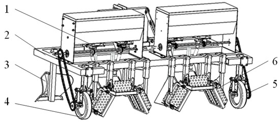
Figure 1.
Schematic diagram of the overall structure of furrow-up fertilizer applicator. 1. Fertilizer apparatus; 2. Rack; 3. Furrower; 4. Ground wheel; 5. Transmission device; 6. Suppression device.
The fertilizer apparatus is mainly composed of a fertilizer box, a support plate, a vertical variable cavity fertilizer discharge device, a fertilizer delivery pipe, a fertilizer discharge shaft, and fertilizer boots (Figure 2).
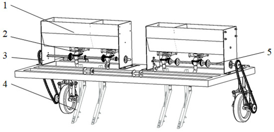
Figure 2.
Structure diagram of fertilizer apparatus. 1. Fertilizer box; 2. Vertical variable cavity fertilizer apparatus; 3. Support plate; 4. Fertilizer boots; 5. Fertilizer discharging shaft.
The whole fertilizing device is fixed with the frame through bolt connection of the support plate, which is divided into two fertilizer boxes. Each fertilizer box is divided into two parts, and loaded with organic fertilizer and compound fertilizer, respectively. Different fertilizers correspond to different sizes of fertilizer drainers, realizing the purpose of applying two different fertilizers at once. The parts of the fertilization device are connected with bolts, and the ground wheel is connected with the fertilizer discharging shaft through a chain. During the fertilization operation, the ground wheel drives the fertilizer discharge shaft to rotate the fertilizer. After the fertilizer is discharged from the fertilizer drainer, it enters the fertilizer boot under the action of gravity and is then applied to the soil.
3. Design of Vertical Variable Cavity Fertilizer Drainer
3.1. Design of Fertilizer Drainer
3.1.1. Structure and Working Principle
The structure of the vertical variable cavity fertilizer drainer mainly includes the upper plate of the fertilizer drainer, a cavity regulator, a fertilizer drainer, the lower plate of the fertilizer drainer, a rotating shaft, a fertilizer conveying pipe, a supporting column, and set screws (Figure 3).
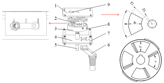
Figure 3.
Structure of vertical variable cavity fertilizer drainer. 1. The upper board; 2. Cavity regulator; 3. Fertilizer disk; 4. The bottom board; 5. Rotary shaft; 6. Fertilizer pipe; 7. Support column; 8. Set screw; 9. The filling orifice of fertilizer disk. Note: B1 is the width of the fertilizer opening of the organic fertilizer box, in mm; r1 is the outer radius of the filling orifice, in mm; r2 is the inner radius of the filling orifice, in mm; θ is the maximum opening of the fertilizer disk, in °; b1 is the width of the fertilizer opening of the organic fertilizer discharge disk, in mm; α is the opening degree of the fertilizer discharge tray, in °.
The fertilizer drainer is connected under the fertilizer box by bolts, and parts of the fertilizer drainer are also fixed by bolts. The fertilizer orifice of the upper board and the bottom board of the fertilizer discharge device is established in a staggered position to avoid fertilizer leakage, and the fertilizer application amount can be accurately controlled. The whole fertilizer drainer adopts a vertical structure, and the movement of fertilizer in the drainer is horizontal, which can improve the pulsation of the process of fertilizer drainage.
The working process of the fertilizer drainer is divided into two steps: 1. Cavity adjustment: The adjustment of the cavity changes the opening degree of the fertilizer disk (“α” in Figure 3) by rotating the cavity regulator, so as to change the volume of the cavity. The indicator line engraved on the cavity regulator corresponds to different opening degrees, and the appropriate opening is selected according to the requirements of the fertilizer application; then, the opening size is fixed by a set screw. 2. Fertilizer discharge: during the fertilization operation, the fertilizer falls from the fertilizer box under the action of gravity and enters the cavity of the fertilizer disk through the filling orifice. Following the rotation of the fertilizer disk, the fertilizer is discharged from the lower plate of the fertilizer orifice of the fertilizer discharge device and sent to the fertilizer boot through the fertilizer delivery pipe, and finally discharged into the inside of the ridge body.
3.1.2. Anti-Arch Design for Filling the Orifice of the Fertilizer Disk
Due to its smaller average diameter and poor fluidity, the problem of arch blockage can easily occur when the traditional fertilizer apparatus is used to discharge fertilizer. This blockage phenomenon often occurs in the filling orifice of the disk, where the cross-section area changes greatly. Therefore, the structure and size design of the filling orifice is important.
For general materials, to prevent the arch formation at the filling outlet, it is necessary to make the hydraulic radius, R, greater than the maximum hydraulic radius, R1, to form an “arch formation”:
where is the initial shear strength of the material, in Pa; is the internal friction angle of material, in °; is the bulk density of the material, in kg/m3; and g is the acceleration of gravity, in m/s2.
The formula of the hydraulic radius is:
where is the section area of the filling orifice, in mm2; and is the section circumference of filling orifice, in mm.
For the filling orifice designed in this paper, its respective section area and section perimeter are:
where
- is the outer radius of the filling orifice, in mm
- is the inner radius of the filling orifice, in mm
- is the width of the filling orifice, in mm
- is the opening degree of the filling orifice, in °
Considering that the overall size should not be too large and the installation space be reserved for the rotating shaft, r2 was determined to be 25 mm. In this paper, we designed the plate for the disk, and the disk cavity was created as a circle (Figure 3). Considering the uniformity of the overall fertilizer discharge, the fertilizer discharge interval between each cavity should not be too large. At the same time, the difficulty of processing and the reliability of the structure resulted in four cavities being set, and the maximum opening of each cavity was 60°, which could be adjusted (Figure 3). The bulk density was 635 kg·m−3, the internal friction angle was 25.24°, and the initial shear strength was 28 Pa.
Combining the above expressions and substituting relevant data, the value of B1 was 18.46 mm. The theoretical calculation results were verified by EDEM discrete element simulation analysis. A simple model of fertilizer boxes was established and imported into the EDEM. The selection of the B1 width was based on the average diameter, D, of the fertilizer particles applied. We selected 1.5 D, 2 D, and 3 D for simulation experiments (Figure 4). The simulation results demonstrated that when the B1 width was 1.5 D, the fertilizer particles were barely discharged from the fertilizer box and could not work normally. At 2 D, the fertilizer began to drain from the box, but it was intermittent, with poor stability and uniformity. At 3 D, the fall of fertilizer was relatively uniform and stable. Overall, these findings were similar to the circular filling orifice designed in this paper, and a relatively uniform and stable fertilizer discharge was achieved when the radius was 60° and its width was three times or more that of the diameter of the applied fertilizer particles. The diameter of the organic fertilizer particles ranged from 3–6 mm, and the B1 should be larger than 18 mm. The simulation results were close to the theoretical analysis results, which verified the correctness of the principle of preventing arch formation.
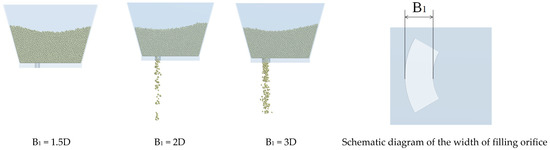
Figure 4.
Simulation experiment of fertilizer discharge in different widths of organic fertilizer boxes.
3.1.3. Basic Structural Parameters of the Fertilizer Disk
After preliminarily determining the size range of the width, B1, of the fertilizer opening of the fertilizer box, the basic structural parameters of the fertilizer discharging tray were designed according to requirements for fertilizer application. The fertilizer discharge quantity, q, in a single turn of the fertilizer disk can be obtained from Equation (6):
where is the filling coefficient of the fertilizer particle in the mold cavity; is the fertilizer particle bulk density, in g/cm3; S is the area of a single cavity, in mm2; is the thickness of the fertilizer disk, in mm; and is the number of cavities.
The amount of fertilizer discharge in a single turn is related to the number of cavities, cavity area, thickness, and filling coefficient of the disk. When the thickness of the fertilizer disk, h is too large, the fertilizer cannot easily fill the mold cavity. At the same time, based on the requirements for the fertilizer application rate, if the diameter of the disk is too large, and if the linear velocities of the outer particles are too large, the fertilizer particles will grind and affect the fertilizer discharge performance. Thus, the width of the fertilizer disk cavity, B1, was set to six times the average size of the fertilizer particles. In addition, the width, B1, of the filling orifice of the fertilizer disk was slightly larger than the width, B1, of the cavity of the fertilizer disk, to improve the filling rate. The final determination of each size of the fertilizer discharge device was: the width of the filling orifice of the organic fertilizer disk, B1, was set to 32 mm, and the width of the cavity of the organic fertilizer disk, b1, was selected as 30 mm. Similarly, the filling orifice width, B2, of compound fertilizer disk was set as 17 mm, and the cavity width, b2, of compound fertilizer disk was set as 15 mm. After determining each size of the cavity, according to the requirements for fertilizer application, a thickness of 35 mm was set for the fertilizer disk, h The cavity opening of the disk could be adjusted between 30–60°. Assuming that the filling coefficient was 1, the theoretical fertilizer application rate of organic fertilizer in a single rotation was 45–100 g, and the fertilizer discharge rate of compound fertilizer in a single rotation was 18–40 g. The traveling speed of the general machine and tool operation was 0.6 m/s, and the fertilizer application rate of organic fertilizer in a single rotation, under the condition of the rotation speed of the disk at 60 rpm, was 48–72 g. The requirement for compound fertilizer was 20–32 g, which meets the requirement for fertilizer application (Organic fertilizer: 675–1050 kg/hm2, Compound fertilizer: 300–450 kg/hm2).
3.2. Establishment of Discrete Element Model and Design of Simulation Test
To further verify the filling performance and discharging performance of the vertical variable cavity drainer, EDEM software was used to conduct a simulation experiment of the discharging fertilizer, and to analyze the discharging performance of the drainer under different discharging disc cavity openings and rotating speeds.
3.2.1. Establishment of Simulation Model and Selection of Material Characteristic Parameters
The fertilizer apparatus model was established in the three-dimensional modeling software SolidWorks2016, and then imported into the discrete element software EDEM2.6 Geometry. The contact model of the fertilizer particles was set as the software default Hertz–Mindlin non-sliding contact model [16,17,18], the Rayleigh time step was set as 2.6 × 10⁻⁵ s, and the simulation of the fertilizer discharge test was performed at different speeds under opening degrees of 30°, 45°, and 60°, to verify the performance of the fertilizer apparatus [19,20].
High carbon-based organic fertilizer for the tobacco field was used as the research object, and simulation parameters were selected as shown in Table 1 [21].

Table 1.
Variable parameter.
First, a particle factory at the upper end of the fertilizer box was established, and the particle generation rate was set to 10,000 per second, with a total of 30,000 articles. The rotational speed of the fertilizer disk was set to 30, 60, 90, 120, and 150 rpm. Then, a long plane was set at a distance of 100 mm from the bottom of the fertilizer discharging device, and the set plane moved backward at a speed of 0.6 m/s to simulate the forward movement of the fertilizer discharging device in the actual fertilizer discharging process. After all fertilizer particles were generated, the fertilizer removal device and the ground began to move, and the real fertilizer removal process was simulated to make the simulation results more realistic.
3.2.2. Simulation Experiment Design of Fertilizer Removal
To accurately reflect the simulation effect of the variable cavity fertilizer discharge device under the two working states of maximum fertilizer discharge and minimum fertilizer discharge, the simulation experiment was carried out with organic fertilizer as an example, with reference to the evaluation method in NY/T 1003-2006 “Fertilizer Machinery Quality Evaluation Technical Specification”, and the coefficient of variation of fertilizer discharge uniformity was taken as the evaluation index. To avoid unstable manure discharge in the beginning and end areas of the simulation test (Figure 5), an area of 1200 mm in the middle of the simulated ground was selected as the sampling area for the fertilizer discharge effect. The grid bin group was set on the simulated ground, and the selected area was evenly divided into four horizontal grids, with the length of each grid at 300 mm.
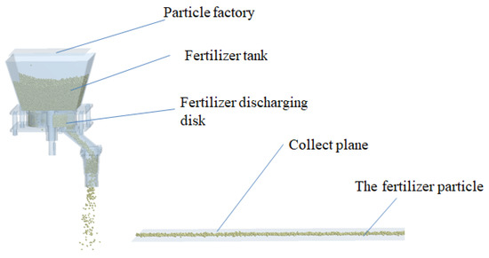
Figure 5.
EDEM simulation.
According to the simulation results, the quality of the fertilizer particles in each grid was counted, and the simulation test was repeated multiple times for accurate statistical analysis, and to calculate the variation coefficient of fertilizer uniformity. The calculation formula is:
where is the mass of fertilizer particles in the ith grid sampled, in g; is the average mass of manure discharge in the samples, in g; is the standard deviation, in g; is the coefficient of variation of uniformity of fertilizer discharge, in%.
The coefficient of variation of fertilizer discharge uniformity was taken as the evaluation parameter of the fertilizer discharge uniformity and the stability of the fertilizer discharge device. The smaller the value, the better the fertilizer discharge uniformity and stability of the fertilizer discharge device.
3.3. Single Factor Test and Analysis
According to the simulation test method, after the simulation, the quality of the fertilizer particles in the sampling area under different opening degrees and different speeds was counted (Figure 6). The fertilizer discharge in the sampling interval initially increased and then decreased with increasing rotational speed. This occurred because when the rotational speed was too high, the filling coefficient of the fertilizer cavity decreased, and the fertilizer discharge ability of the fertilizer disk gradually decreased with a continuous increase in the rotational speed. The fertilizer discharge rate of a single rotation obtained by the simulation was 36–74 g, which met the demand of the fertilizer application rate.
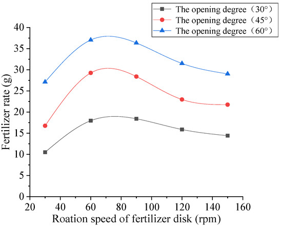
Figure 6.
Simulation results of the variation of the amount of fertilizer discharge with the rotation speed under different opening degrees.
According to Equations (7)–(9), the variation coefficient of fertilizer discharge can be calculated to obtain the variation of fertilizer discharge coefficient with the change in rotational speed under different opening degrees of the fertilizer discharge tray, as shown in Figure 7. The uniform coefficient of variation first declined and then increased with increasing opening degree. The increase in the opening reduced the interval between adjacent cavities; therefore, the uniformity could be improved. The fertilizer outlet first increased and then shrank during fertilizer discharge, and the fertilizer particle discharge exhibited the same trend, which was reflected in the phenomenon of less fertilizer at both ends and more in the middle on the collecting plane (Figure 8). After the opening increased, the cavity volume of the disk increased, and this phenomenon was more evident. Therefore, the opening continued to increase, and uniformity decreased, but it was still within the range of design requirements. The uniform coefficient of variation first decreased and then increased with increasing rotation speed. This occurred because with increasing rotation speed, the fertilizer discharge time interval between the two adjacent cavities declined, and the overall fertilizer discharge uniformity increased. However, when the speed was too high, it was difficult to discharge fertilizer (Figure 9), and the fertilizer discharge uniformity decreased. In addition, with increasing opening degree, the minimum point of the variation curve of the uniform coefficient of variation with the influence of rotation speed moved backward because the ability of filling and discharging fertilizer increased with a larger opening degree.
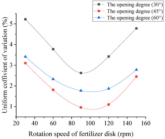
Figure 7.
Variation of coefficient of variation of fertilizer discharge with rotational speed under different opening degrees.
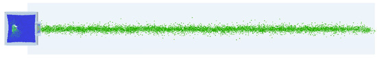
Figure 8.
Top view of the collection plane.
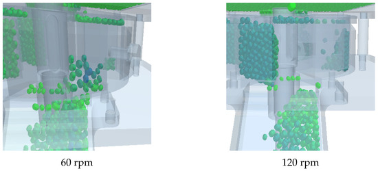
Figure 9.
Particles remaining in the cavity after rotation speeds of 60 rpm (left image) and 120 rpm (right image).
The simulation results showed that the variation coefficient of uniformity of fertilizer discharge device varied from 0.96–5.22% under different speed and opening conditions, which aligned with the design requirements for fertilizer discharge devices and the application requirements for precise tobacco fertilization.
3.4. Orthogonal Test and Analysis
From the single factor test, when the rotational speed of the fertilizer apparatus was between 60–120 rpm, the fertilizing device had the largest amount of fertilizer and better uniformity of fertilizer. A forward speed of 0.6 m/s was selected and openings of 30°, 45° and 60° were set with speeds of 60 rpm, 90 rpm and 120 rpm, respectively, for the three levels of orthogonal testing, to analyze the interaction between the rotational speed of the fertilizer tray and the opening of the fertilizer tray cavity on fertilization performance.
According to the experimental results, the relationship diagram of the influence of rotation speed and opening degree on the variation coefficient of fertilizer application rate and fertilizer discharge uniformity was drawn. As shown in Figure 10, the isometric plot and response surface of fertilizer application rate increased with increased opening, when the rotation speed was constant. When the opening degree was fixed, the fertilizer application rate increased slightly at first, and then decreased with an increase in the rotation speed. Comparing the effects of the two factors on fertilizer application rate, the slope of the curve of the change curve of fertilizer application rate with the opening rate was larger than the change curve of fertilizer application rate with rotating speed. Therefore, the effect of the opening rate on fertilizer application rate was greater than that of the rotating speed. The maximum value of fertilizer application appeared at 60° and 87 rpm.
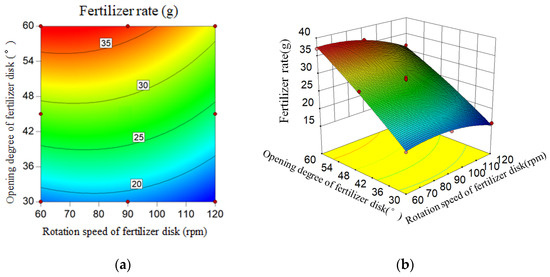
Figure 10.
Relationship between fertilizer application rate and the rotation speed and opening of fertilizer disk. (a) Contour map; (b) Response surface.
Figure 11 shows the contour map and response surface of the uniformity coefficient of variation, which was at a low level in the opening, and the uniformity coefficient of variation was large. With an increase in opening degree, the uniformity coefficient of variation initially declined, and then increased. When the opening degree was constant, the uniformity coefficient of variation first decreased, and then increased with rising rotational speed. By comparing the influence of the two factors on the coefficient of variation of uniformity of fertilizer discharge, the slope of the curve of variation coefficient of uniformity of fertilizer discharge with the opening degree was clearly larger than with the rotating speed; thus, the influence of the opening degree on the coefficient of variation of uniformity was greater than that of the rotating speed. The minimum value of the coefficient of variation of fertilizer discharge uniformity appeared at 47.9° and 100 rpm.
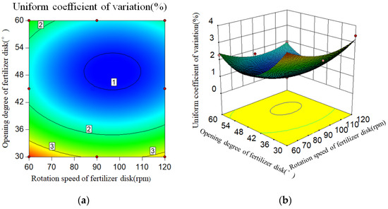
Figure 11.
The relationship between the coefficient of uniformity variation and the rotation speed and opening of the fertilizer disk. (a) Contour map; (b) Response surface.
4. Verification Test
4.1. Bench Test
A physical model of a fertilizer discharging device was made and a platform was built for the fertilizer discharging test, as shown in Figure 12. A servo motor was used as the power source to drive the platform and the fertilizer discharging device. A layer of soil was laid flat on the ground to simulate the contact between fertilizer and soil during normal fertilization operation, and a thin layer of cotton cloth was set on the soil to collect fertilizer particles. The platform discharging test was carried out according to the process of the simulation discharging test. High carbon-based organic fertilizer and potassium sulfate compound fertilizer were used as test objects and the opening of the fertilizer disk cavity was adjusted. A speed test was performed multiple times to collect and weigh the fertilizer plant for statistical analysis. Each group was repeated 10 times and the distributing uniformity coefficient of variation was calculated.
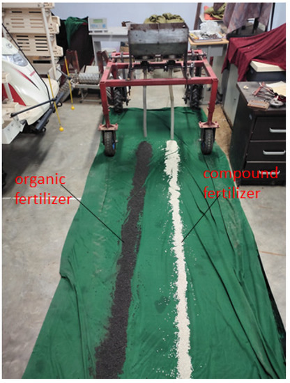
Figure 12.
Verification test site map.
The fertilizer quality collected on the ground was repeatedly measured, and the coefficient of variation was calculated. The statistical results of the organic fertilizer discharge device are shown in Figure 13.
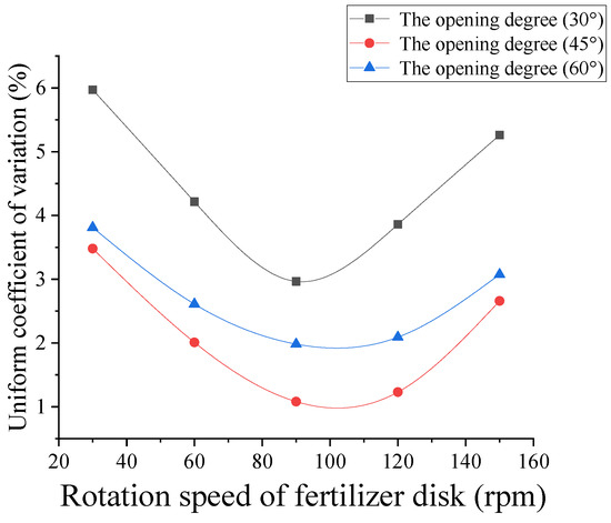
Figure 13.
Analysis of coefficient of variation results of bench test.
According to the bench test results, the minimum value of the variation coefficient of fertilizer discharge was 1.08%, and the maximum value was 5.97%, which corresponded with the design requirements for the fertilizer discharge device. Meanwhile, the variation law of the variation coefficient was consistent with the simulation test, which verified the correctness of the simulation test and the feasibility of the discrete element analysis.
4.2. Field Experiment
To further verify the reliability of the designed fertilizer apparatus, a prototype of a furrow-up fertilizer applicator was made for a field experiment in the Science and Education Park of Henan Agricultural University (Figure 14). The power was provided by a four-wheel-drive tractor of the Dongfanghong Agricultural Machinery LX904. The basic physical properties of the soil were measured, and the average soil water content was 18.06%. The average speed of the tractor in the experiment was 0.6 m/s, the rotation speed of the fertilizer disk was 90 rpm, and the cavity opening of the fertilizer disk was 45°. It was difficult to collect the fertilizer, because it was applied directly into the soil. In this experiment, the soil profile was taken after the fertilization operation, and the fertilizer was weighed and counted after the soil was removed. The results are shown in Figure 15.
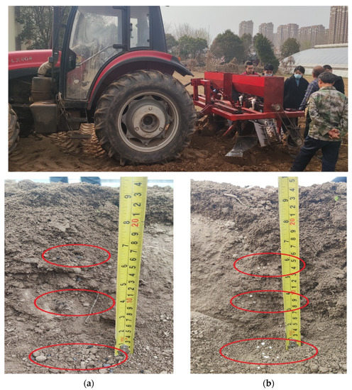
Figure 14.
Field test. (a) Organic fertilizer, (b) Compound fertilizer.
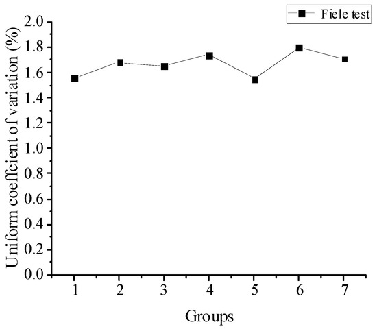
Figure 15.
Analysis of uniform coefficient of variation in the field test.
The minimum coefficient of variation of uniformity of fertilizer discharge was 1.55% and the maximum was 2.2%. The results of the field experiment were larger than those of the simulation experiment and bench experiment. This is because, when compared with the simulation experiment, there were some uncontrollable influencing factors in the field experiment, such as the error of machine processing, and there was a more complex and unstable soil environment than in the simulation, which led to a decrease in uniformity. However, the test results still conformed to the design standard NY/T 1003-2006, and the experimental results still offered a certain reference value.
5. Conclusions
- (1)
- A vertical variable cavity base fertilizer matching application device was designed, which could effectively solve problems associated with a traditional fertilizer apparatus, such as blockage, uneven fertilizer discharge, and leakage in the non-fertilizer discharge stage, and could realize precise and stable fertilization. Here, the working principle of the device was described, and the basic structural parameters of the device were determined. The size of the filling orifice of the fertilizer disk was analyzed through a simulation test, which indicated that when the width, B1, of the filling orifice was larger than 18.4 mm, a more uniform and stable fertilizer discharge could be achieved.
- (2)
- The structure size of the two corresponding designs to different kinds of fertilizers was determined. The width, B1, at the orifice of the organic fertilizer box was 32 mm, and the width, B1, of the orifice of the organic fertilizer disk was 30 mm. The width, B2, of the orifice of the compound fertilizer box was 17 mm, and the width, B2, of the orifice of the compound fertilizer disk was 15 mm.
- (3)
- With a fertilizer disk of rotational speed and opening factors, the single factor experiment and orthogonal experiment were designed by EDEM and performed on the simulation. The results concluded that the uniformity coefficient of variation range of was 0.96~5.22%. Finally, the bench test and field experiment of fertilizer plant fertilization performance verification were conducted, and produced results consistent with the results of simulation. These results can meet the operation requirements for both the fertilizer plant and precise fertilization of tobacco, as well as provid a reference for the design of the fertilizer plant.
Author Contributions
Conceptualization, X.Z., Y.P. and X.L.; methodology, X.Z., Y.P. and X.L.; software X.Z. and X.L.; validation X.Z., Y.P., X.L. and Y.C.; formal analysis X.Z., Y.P. and Q.S.; investigation, X.Z., Y.C., Y.X. and P.Z.; data curation, X.Z. and X.L.; writing–original draft preparation, X.Z.; writing–review and editing, X.Z., Y.P. and X.L.; visualization, Q.S. and P.Z.; supervision, Y.P., Y.C., Q.S., Y.X. and P.Z.; project administration, X.Z., Y.C., Y.X. and P.Z.; funding acquisition, X.Z. and Y.C. All authors have read and agreed to the published version of the manuscript.
Funding
This research was funded by the National Natural Science Foundation of China, grant number 52005167, and the Science and Technological Research Project in Henan Province, grant number 222102110354.
Institutional Review Board Statement
Not applicable.
Data Availability Statement
Not applicable.
Acknowledgments
The authors would like to thank the technical support of their teacher and supervisor. We also appreciate the assistance provided by team members during the experiments. Additionally, we sincerely appreciate the work of the editor and the reviewers of the present paper.
Conflicts of Interest
The authors declare no conflict of interest.
References
- Balafoutis, A.; Beck, B.; Fountas, S.; Vangeyte, J.; Van Der Wal, T.; Soto, I.; Gómez-Barbero, M.; Barnes, A.; Eory, V. Precision agriculture technologies positively contributing to GHG emissions mitigation, farm productivity, and economics. Sustainability 2017, 9, 1339. [Google Scholar] [CrossRef]
- Wang, H.; Xu, J.; Liu, X.; Zhang, D.; Li, L.; Li, W.; Sheng, L. Effects of long-term application of organic fertilizer on improving organic matter content and retarding acidity in red soil from China. Soil Tillage Res. 2019, 195, 104382. [Google Scholar] [CrossRef]
- Guo, J.H.; Liu, X.J.; Zhang, Y.; Shen, J.L.; Han, W.X.; Zhang, W.F.; Christie, P.; Goulding, K.W.T.; Vitousek, P.M.; Zhang, F.S. Significant acidification in major Chinese croplands. Science 2010, 327, 1008–1010. [Google Scholar] [CrossRef] [PubMed]
- Gong, L.; An, J.W.; Xing, Y.H.; Liu, Y.; Sun, W.T. Effects of continuous subsoiling and organic fertilization on corn yield and soil fertility. Soils 2016, 48, 1092–1099. [Google Scholar] [CrossRef]
- Zhang, J.Q.; Liu, G.; Hu, H.; Jiayun, H. Development of bivariate fertilizer control system via independent control of fertilizing unit. Trans. CSAE 2021, 37, 38–45. [Google Scholar] [CrossRef]
- Villette, S.; Piron, E.; Cointault, F.; Chopinet, B. Centrifugal spreading of fertiliser: Deducing three-dimensional velocities from horizontal outlet angles using computer vision. Biosyst. Eng. 2007, 99, 496–507. [Google Scholar] [CrossRef]
- Villette, S.; Cointault, F.; Piron, E. Centrifugal spreading: An analytical model for the motion of fertiliser particles on a spinning disc. Biosyst. Eng. 2005, 92, 157–164. [Google Scholar] [CrossRef]
- Coetzee, C.J.; Lombard, S.G. Discrete element method modelling of a centrifugal fertiliser spreader. Biosyst. Eng. 2011, 109, 308–325. [Google Scholar] [CrossRef]
- Zha, X.; Zhang, G.; Han, Y.; Salem, A.; Fu, J.; Zhou, Y. Structural optimization and performance evaluation of blocking wheel-type screw fertilizer distributor. Agriculture 2021, 11, 248. [Google Scholar] [CrossRef]
- Liu, Z.D.; Wang, Q.J.; Liu, C.G.; Li, H.; Liu, J. Design and experiment of precision hole-fertilizing apparatus with notched plate. Trans. CSAM 2018, 49, 137–144, 355. [Google Scholar] [CrossRef]
- Liu, Z.D.; Wang, Q.J.; Li, H.W.; Jin, H.; Caiyun, L.; Lijuan, X. Design of flexible fertilizer protection mechanism for hole-fertilizing apparatus with notched plate. Trans. CSAM 2018, 49, 97–103. [Google Scholar] [CrossRef]
- Przywara, A.; Santoro, F.; Kraszkiewicz, A.; Pecyna, A.; Pascuzzi, S. Experimental study of disc fertilizer spreader performance. Agriculture 2020, 10, 467. [Google Scholar] [CrossRef]
- Alameen, A.A.; Al-Gaadi, K.A.; Tola, E.K. Development and performance evaluation of a control system for variable rate granular fertilizer application. Comput. Electron. Agric. 2019, 160, 31–39. [Google Scholar] [CrossRef]
- Wang, J.F.; Gao, G.B.; Weng, W.X.; Jinwu, W.; Dongwei, Y.; Bowen, C. Design and experiment of key components of side deep fertilization device for paddy field. Trans. CSAM 2018, 49, 92–104. [Google Scholar] [CrossRef]
- Wang, J.W.; Zhou, W.Q.; Bai, H.C.; Jinfeng, W.; Huang, H.; Wang, Z. Design and experiment of differential-type bidirectional distribution device for fertilizer supply for deep-fertilizer liquid fertilizer application. Trans. CSAM 2018, 49, 105–111. [Google Scholar] [CrossRef]
- Zhan, Z.; Yaoming, L.; Zhenwei, L.; Zhiqiang, G. DEM simulation and physical testing of rice seed impact against a grain loss sensor. Biosyst. Eng. 2013, 116, 410–419. [Google Scholar] [CrossRef]
- Huang, Y.X.; Hang, C.G.; Yuan, M.C.; Wang, B.; Zhu, R. Discrete element simulation and experiment on disturbance behavior of subsoiling. Trans. CSAM 2016, 47, 80–88. [Google Scholar] [CrossRef]
- Wang, B.T.; Bai, L.; Ding, S.P.; Yao, Y.X.; Huang, Y.X.; Zhu, R.X. Simulation and experimental study on impact of fluted-roller fertilizer key parameters on fertilizer amount. J. Chin. Agric. Mech. 2017, 38, 1–6. (In Chinese) [Google Scholar] [CrossRef]
- Van Liedekerke, P.; Tijskens, E.; Dintwa, E.; Rioual, F.; Vangeyte, J.; Ramon, H. DEM simulations of the particle flow on a centrifugal fertilizer spreader. Powder Technol. 2009, 190, 348–360. [Google Scholar] [CrossRef]
- Ding, S.; Bai, L.; Yao, Y.; Yue, B.; Fu, Z.; Zheng, Z.; Huang, Y. Discrete element modelling (DEM) of fertilizer dual-banding with adjustable rates. Comput. Electron. Agric. 2018, 152, 32–39. [Google Scholar] [CrossRef]
- Zhang, X.L.; Wu, Y.W.; Li, J.H.; Wang, L.F.; Tong, Z.W.; Chen, X.T. Design and experiment of tobacco pellet fertilizer mixture applicator. J. Henan Agric. Univ. 2020, 221, 829–835. [Google Scholar] [CrossRef]
Publisher’s Note: MDPI stays neutral with regard to jurisdictional claims in published maps and institutional affiliations. |
© 2022 by the authors. Licensee MDPI, Basel, Switzerland. This article is an open access article distributed under the terms and conditions of the Creative Commons Attribution (CC BY) license (https://creativecommons.org/licenses/by/4.0/).