Complex Event Processing Methods for Greenhouse Control


Abstract
:1. Introduction
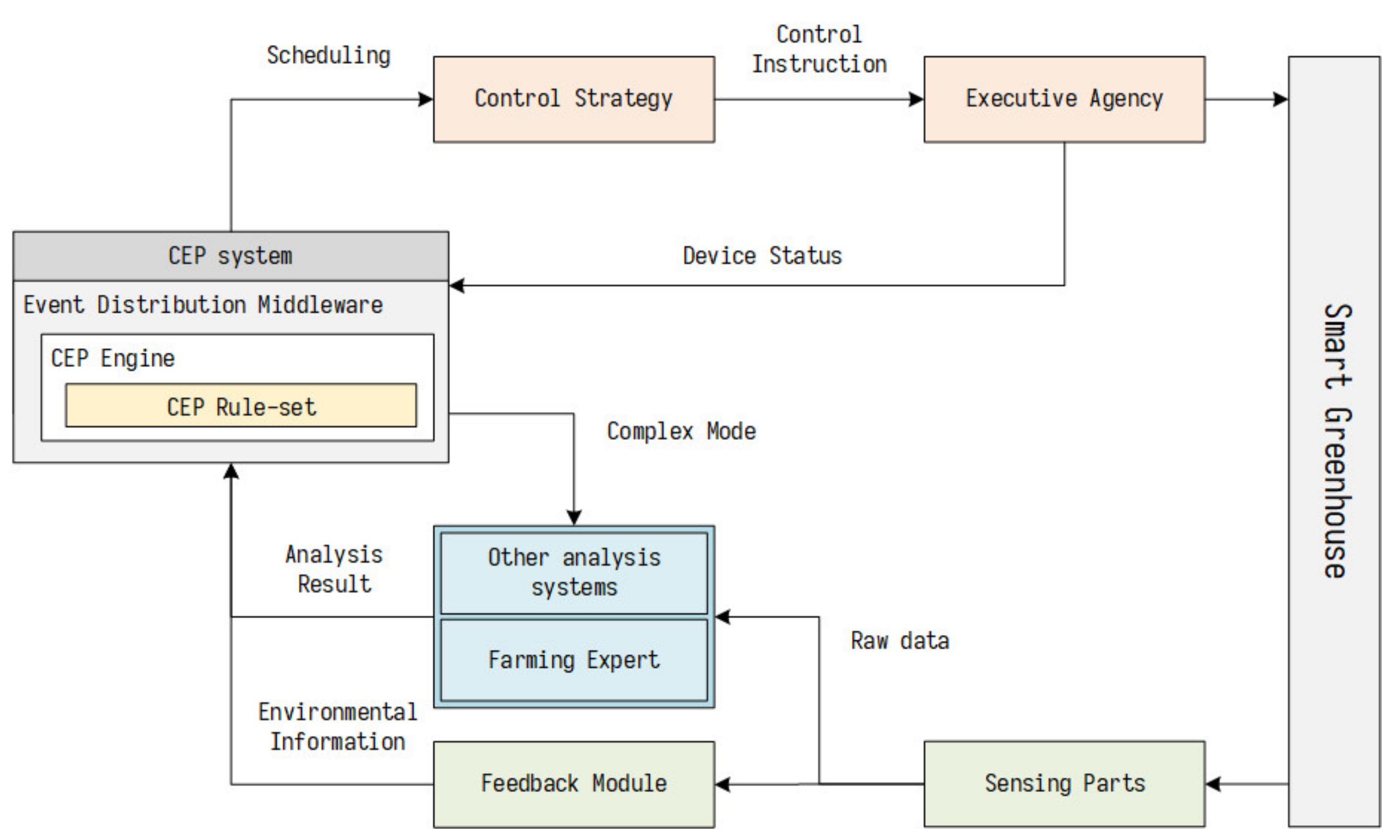
- This article innovatively applies CEP technology to the intelligent control of agricultural greenhouses. By analyzing the commonalities and differences of many agricultural issues, we propose an effective, greenhouse-oriented complex event processing system structure. It is of great significance to promote the extensive application of CEP technology in the greenhouse field;
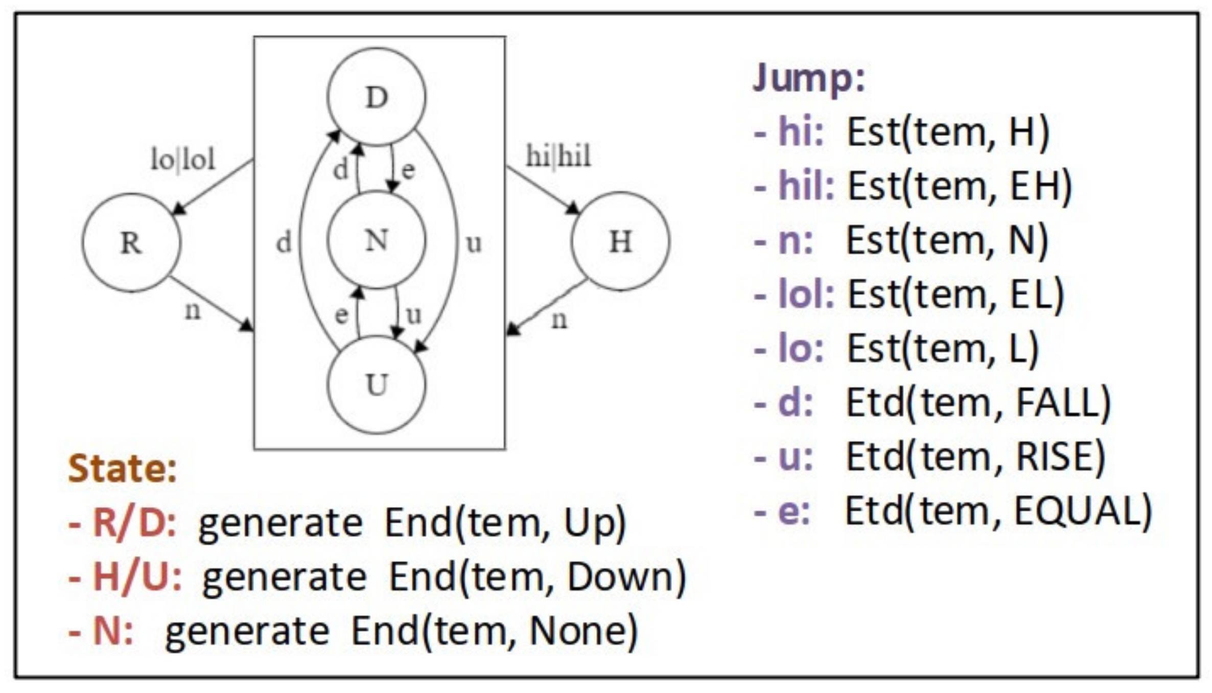
- We have improved the automata algorithm for event aggregation, which allows CEP technology to be used more flexibly in complex greenhouse scenarios. Our algorithm includes 13 types of event processing agent types, 21 types of typical events involved in greenhouse automatic control, which can correspond to the seven most common specific agricultural problems;
- This work incorporates knowledge in related greenhouse research fields such as greenhouse planting schemes. It gives full play to the advantages of various control methods to deal with the different control characteristics that need to be solved in the greenhouse environment.
2. Related Work
3. Complex Event Processing Algorithm for Greenhouses
3.1. Overall Introduction
3.2. Complex Event Processing Logical Relationships
3.3. The Event Definition
- <> Angle brackets are used to separate strings that are the names of grammatical elements. If a triple with “e.g.,” as the second element appears in the angle brackets, the triple is a type of terminal symbol with a specific meaning. The first element is the category name of this type of terminal symbol, and the third element is some examples of this type of terminal symbol;
- ::= The operator used for definition. Represents that the syntax element on the left can be replaced by the string appearing on the right;
- [] The elements in square brackets can appear 0 or 1 times;
- / The vertical line indicates that the element on the left can be replaced by the element on the right.


- Environmental trends, which mainly reflect environmental changes, are usually obtained by differential or forecasting of environmental information and need to indicate the start and end times, the specific structure of which is as follows:
![Agriculture 11 00811 i003]()
- Control method, which simply distinguishes the type of method called by name, as follows:
![Agriculture 11 00811 i004]()
- System configuration information, which includes executable commands and some descriptions, as follows:
![Agriculture 11 00811 i005]()


- Input information (the simplest atomic event). This information originates from other information objects and acts on the control system and is the basis for the calculation of control system reasoning, as shown in Table 1.
- Intermediate information (intermediate-level complex events). This message is not directly related to the input and output of the control system, but is used as a carrier of reasoning results in the control system, as shown in Table 2.
- Output information (highest level complex events). This information originates from the control system, acts on other information objects, determines the control action of the controller, and makes it easy for workers to know about the green-house, which is an important part of the realization of automatic control, as shown in Table 3.
3.4. EPA Definition
4. Case Study
5. Experiments
6. Conclusions
7. Patents
Author Contributions
Funding
Institutional Review Board Statement
Informed Consent Statement
Data Availability Statement
Conflicts of Interest
Abbreviations
| CEP | Complex event processing |
| EPA | Event processing agent |
| EPN | Event processing network |
| BNF | Backus Naur Form |
| BES | Basic event structure |
References
- Marcu, I.; Suciu, G.; Balaceanu, C.M.; Vulpe, A.; Drăgulinescu, A.-M. Arrowhead technology for digitalization and automation solution: Smart cities and smart agriculture. Sensors 2020, 20, 1464. [Google Scholar] [CrossRef] [Green Version]
- De Oliveira, R.L.M.; Santos, I.V.; Graciano, G.F.; Libânio, A.A.C.; de Oliveira, L.K.; Bracarense, L.D. A sustainable approach for urban farming based on city logistics concepts for local production and consumption of vegetables. Res. Transp. Econ. 2021, 87, 101038. [Google Scholar] [CrossRef]
- Lujuan, D.; Qiaoling, F.; Shujun, L.; Yuelan, N.; Baozhen, L. Research status and development direction of intelligent greenhouse environment control. J. Zhengzhou Univ. Light Ind. 2003, 4, 20–23. [Google Scholar]
- Wang, Z.; Gai, S.; Cui, Y.; Dong, J. Research on intelligent agriculture system based on digital twins and blockchain. J. Hebei Acad. Sci. 2021, 38, 66–73. [Google Scholar]
- Juan, N.; Ruizhi, S.; Xuefeng, D.; Hao, Y. Processing of uncertain and complex events in precision agriculture based on data lineage management. Trans. Chin. Soc. Agric. Mach. 2016, 47, 245–253. [Google Scholar]
- Li, X.; Gao, H.; Qiao, Y.; Wang, H. Real time complex event processing engine for Internet of things. Small Microcomput. Syst. 2015, 36, 2047–2053. [Google Scholar]
- Huang, Y.; Zhu, X. Design of multi-dimensional agricultural ecological intelligent control system based on green manufacturing. Mod. Bus. Trade Ind. 2019, 40, 193–194. [Google Scholar]
- Ji, P.; Fu, Y.; Yang, B. Research on multivariable decoupling control of greenhouse system based on single neuron PID. Chin. J. Agric. Mach. Chem. 2020, 41, 143–147. [Google Scholar]
- Alipour, M.; Loghavi, M. Development and evaluation of a comprehensive greenhouse climate control system using artificial neural network. Univers. J. Control. Autom. 2013, 1, 10–14. [Google Scholar] [CrossRef]
- Huansen, F.; Yuangui, L.; Xuelian, Z.; Hu, C. Application of intelligent expert system in vegetable greenhouse planting. Chin. J. Agric. Mach. Chem. 2014, 35, 240–244. [Google Scholar]
- Wu, X. Research on Key Technologies of Greenhouse Cultivation Expert System. Master’s Thesis, Tianjin University of Technology, Tianjin, China, 2013. [Google Scholar]
- Xiao, D.; Xiu, J. Software Engineering Models and Methods, 2nd ed.; Beijing University of Posts and Telecommunications Press: Beijing, China, 2014. [Google Scholar]
- Hangdong, J.; Zhonghong, L. Analysis of a winter hail weather process. Guangxi Meteorol. 2005, S1, 134–136. [Google Scholar]
- Li, X.; Wang, J.; Gao, H. Spatiotemporal event model for complex event processing of farmland Internet of Things. Trans. Chin. Soc. Agric. Mach. 2015, S1, 153–161. [Google Scholar]
- Li, X.; Wei, X.; Chen, X.; Tang, X.; Xie, T.; Jia, L. Construction and specification of complex events from sensor network data in farmland. Int. Agric. Eng. J. 2017, 26, 269–282. [Google Scholar]
- Luckham, D.; Wantao, L.; Songlin, H. Introduction to Complex Event Handling; Science Press: Beijing, China, 2015. [Google Scholar]
- Wen, B.; Yang, J. Research and application of complex event processing technology. Mech. Eng. Autom. 2018, 6, 27–29. [Google Scholar]
- Dayarathna, M.; Perera, S. Recent advancements in event processing. ACM Comput. Surv. 2018, 51, 1–36. [Google Scholar] [CrossRef]
- Wang, Y.; Zheng, L.; Fan, W. Manufacturing workshop data acquisition and fusion based on standard semantic model and complex event processing under Cloud Architecture. Comput. Integr. Manuf. Syst. 2019, 25, 3103–3115. [Google Scholar]
- Yin, D.; Gong, H. Smart home middleware system based on event matching. Fujian Comput. 2019, 35, 28–30. [Google Scholar]
- Jing, X.; Zhang, J.; Li, J. Complex event processing technology and its application in logistics internet of things. Comput. Appl. 2013, 33, 2026–2030. [Google Scholar]
- Hooper, A.W.; Davis, P.F. Control of greenhouse air temperature with an adaptive control algorithm. Symp. Greenh. Clim. Control 1985, 174, 407–412. [Google Scholar] [CrossRef]
- Ali, I.A.; Abdalla, A.M. A microcomputer-based system for all-year-round temperature control in greenhouses in dry arid lands. Comput. Electron. Agric. 1993, 8, 195–210. [Google Scholar] [CrossRef]
- Xu, D. Research on Optimal Control Algorithm for Double Time Scale Greenhouse Production; China Agricultural University: Beijing, China, 2019. [Google Scholar]
- Kodali, R.; Jain, V.; Karagwal, S. IoT Based smart greenhouse. In Proceedings of the 2016 IEEE Region 10 Humanitarian Technology Conference (R10-HTC), Agra, India, 21–23 December 2016. [Google Scholar]
- Linker, R.; Gutman, P.O.; Seginer, I. Robust controllers for simultaneous control of temperature and CO2 concentration in greenhouses. Control Eng. Pract. 1997, 7, 851–862. [Google Scholar] [CrossRef]
- Bennis, N.; Duplaix, J.; Enéa, G.; Haloua, M.; Youlal, H. Greenhouse climate modelling and robust control. Comput. Electron. Agric. 2008, 61, 96–107. [Google Scholar] [CrossRef]
- Pasgianos, G.D.; Arvanitis, K.G.; Polycarpou, P.; Sigrimis, N. A nonlinear feedback technique for greenhouse environmental control. Comput. Electron. Agric. 2003, 40, 153–177. [Google Scholar] [CrossRef]
- Wu, X.; Zhao, L. Design and MATLAB simulation of non-linear controller for temperature, room temperature and humidity. J. Shenyang Agric. Univ. 2011, 42, 121–124. [Google Scholar]
- Cunha, J.B. Real-time adaptive control for greenhouse heating. In Proceedings of the Cooling and CO2 Enrichment Computers in Agriculture and Natural Resources, Orlando, FL, USA, 23–25 July 2006. [Google Scholar]
- Rodríguez, F.; Guzmán, J.L.; Berenguel, M.; Arahal, M.R. Adaptive hierarchical control of greenhouse crop production. Int. J. Adapt. Control Signal Process. 2010, 22, 180–197. [Google Scholar] [CrossRef]
- Ouammi, A.; Achour, Y.; Dagdougui, H.; Zejli, D. Optimal operation scheduling for a smart greenhouse integrated microgrid. Energy Sustain. Dev. 2020, 58, 129–137. [Google Scholar] [CrossRef]
- Piñón, S.; Camacho, E.F.; Kuchen, B.; Peña, M. Constrained predictive control of a greenhouse. Comput. Electron. Agric. 2005, 49, 317–329. [Google Scholar] [CrossRef]
- Ramirez, A.A. Improving efficiency of greenhouse heating systems using model predictive control. In Proceedings of the 16th IFAC World Congress, Prague, Czech Republic, 3–5 July 2005. [Google Scholar]
- Berenguel, M.; Rodriguez, F.; Guzman, J.L.; Lacasa, D.; Pérez-Parra, J. Greenhouse diurnal temperature control with natural ventilation based on empirical models. Acta Hortic. 2006, 79, 57–64. [Google Scholar] [CrossRef]
- Deng, L.; Zhang, K.; Gong, Y.; Chen, C. Preliminary study on multi-level control system and optimized target value setting of greenhouse environment. Trans. Chin. Soc. Agric. Eng. 2005, 5, 119–122. [Google Scholar]
- Xu, L.; Su, Y.; Liang, Y. Requirements and status quo of control-oriented greenhouse system microclimate environment model. Trans. Chin. Soc. Agric. Eng. 2013, 29, 1–15. [Google Scholar]
- Zhou, R.; Zhang, W. Application and review of greenhouse microclimate environmental model. Res. Agric. Mech. 2011, 33, 189–192. [Google Scholar]
- Zadeh, L.A. Fuzzy Sets, Fuzzy Logic, and Fuzzy Systems: Selected papers by Lotfi. A. Zadeh; Archive for Mathematical Logic: Berlin/Heidelberg, Germany, 1996. [Google Scholar]
- Peng, X.; Liu, G. Intelligent water-saving irrigation system based on fuzzy control and wireless sensor network digital home (ICDH). In Proceedings of the 2012 Fourth International Conference, Washington, DC, USA, 17–19 August 2012; pp. 252–256. [Google Scholar]
- Mei, Z.; Chunhong, L.; Yaoguang, W.; Yingyi, C. Wireless intelligent monitoring system for temperature, room temperature and humidity based on fuzzy control. Agric. Eng. 2013, 3, 47–50. [Google Scholar]
- Wang, Y.; Chai, T. Research summary of adaptive fuzzy control theory. Control Eng. 2006, 3, 193–198. [Google Scholar]
- Ayodele, T.O. Introduction to Machine Learning; MIT Press: Cambridge, MA, USA, 2004. [Google Scholar]
- Bishop, C.M. Pattern Recognition and Machine Learning; Springer: New York, NY, USA, 2006. [Google Scholar]
- Qu, Y.; Ning, D.; Lai, Z.; Cheng, Q.; Mu, L. Neural network PID control of greenhouse temperature control system. Trans. Chin. Soc. Agric. Eng. 2011, 27, 307–311. [Google Scholar]
- Sun, Y.; Cai, Y. Research on greenhouse multi-feature data fusion method based on WDNN. Trans. Chin. Soc. Agric. Mach. 2019, 50, 273–280. [Google Scholar]
- Zadoks, J.C. EPIPRE: A disease and pest management system for winter wheat developed in the Netherlands. Eppo Bull. 2010, 11, 365–369. [Google Scholar] [CrossRef]
- Carey, M.J.; Livny, M.; Jauhari, R. The HiPAC project: Combining active databases and timing constraints. ACM SIGMOD Rec. 1988, 17, 51–70. [Google Scholar] [CrossRef]
- Li, X. Research on real-time reasoning technology based on active rules. Beijing. Grad. Sch. Chin. Acad. Sci. 2011, 11, 25. [Google Scholar]
- Gatziu, S.; Dittrich, K.R. SAMOS: An active object-oriented database system. IEEE Q. Bull. Data Eng. Spec. Issue Act. Database 1992, 15, 23–26. [Google Scholar]
- Gatziu, S.; Dittrich, K.R. Events in an active object-oriented database system 1 2 rule definition language. Rules Database Syst. 1993, 8, 23–39. [Google Scholar]
- Gyllstrom, D.; Wu, E.; Chae, H. SASE: Complex Event Processing Over Streams. In Proceedings of the Third Biennial Conference on Innovative Data Systems Research, Asilomar, CA, USA, 7–10 January 2007; pp. 408–411. [Google Scholar]
- Magid, Y.; Adi, A.; Barnea, M.; Botzer, D.; Rabinovich, E. Application Generation Framework for Real-Time Complex Event Processing. In Proceedings of the 32nd Annual IEEE Int Computer Software and Applications Conference, Turku, Finland, 28 July–1 August 2008; Volume 1, pp. 1162–1167. [Google Scholar]
- Xiao, F.; Zhan, C.; Lai, H.; Tao, L.; Qu, Z. New parallel processing strategies in complex event processing systems with data streams. Int. J. Distrib. Sens. Netw. 2017, 13. [Google Scholar] [CrossRef]
- Paschke, A. A Semantic Design Pattern Language for Complex Event Processing. In Proceedings of the AAAI Spring Symposium—Intelligent Event Processing, Stanford, CA, USA, 23–25 March 2009; pp. 54–60. [Google Scholar]
- Bülow, S.; Backmann, M.; Herzberg, N.; Hille, T.; Meyer, A.; Ulm, B.; Wong, T.Y.; Weske, M. Monitoring of business processes with complex event processing. In Proceedings of the International Conference on Business Process Management, Beijing, China, 26 August 2013; pp. 277–290. [Google Scholar]
- Barquero, G.; Burgueño, L.; Troya, J.; Vallecillo, A. Extending Complex Event Processing to Graph-structured Information. In Proceedings of the 21th ACM/IEEE International Conference, Copenhagen, Denmark, 14–19 October 2018. [Google Scholar]
- Peng, S.; Liu, H.; Guo, X.; He, J. State-based event detection optimization for complex event processing. Sens. Transducers 2014, 164, 242. [Google Scholar]
- Yan, L.; Liao, H.; Su, H. Parallel complex event detection based on regular tree pattern matching. In Proceedings of the 2018 International Conference on Big Data Technologies, Hangzhou, China, 18–20 May 2018; pp. 34–39. [Google Scholar]
- Macia, H.; Valero, V.; Diaz, G.; Ortiz, G. Complex event processing modeling by prioritized colored petri nets. IEEE Access 2016, 4, 7425–7439. [Google Scholar] [CrossRef]
- Ding, K.; Zhang, X.; Deng, B. C-NMSP: A high performance network management service platform for complex event processing international conference on future generation. Commun. Netw. 2008, 1, 7–10. [Google Scholar]
- Mazon-Olivo, B.; Hernández-Rojas, D.; Maza-Salinas, J.; Pen, A. Rules engine and complex event processor in the context of internet of things for precision agriculture. Comput. Electron. Agric. 2018, 154, 347–360. [Google Scholar] [CrossRef]
- Li, P.; Wang, J. Research progress on intelligent management of greenhouse environmental information. J. Agric. Mach. 2014, 45, 236–243. [Google Scholar]
- Deng, X.; Sun, R.; Nie, J.; Wang, W. Modeling of a greenhouse environment monitoring IoT system based on time automata. Trans. Chin. Soc. Agric. Mach. 2016, 7, 301–308. [Google Scholar]
- Apache Kafka: A Distributed Streaming Platform. Available online: https://kafka.apache.org/documentation/ (accessed on 15 June 2021).
- Sun, K. Research on Acquisition and Classification Methods of Time Series Flow Events; Liaoning University: Liaoning, China, 2020. [Google Scholar]
- Li, Y.; Xu, L. Design of a description language for LALR(1) parser based on BNF paradigm. New Technol. New Process 2015, 6, 70–72. [Google Scholar]
- Zhang, L.; Duan, Q.; Li, D. Research on the construction technology of the diagnosis and treatment of corn diseases and insect pests. Agric. Mech. Res. 2012, 34, 41–45. [Google Scholar]
- Xiuli, H.; Zhi, C. Design and implementation of heterogeneous web platform based on JSON. Comput. Technol. Dev. 2021, 31, 120–125. [Google Scholar]
- Liu, H.; Xiong, W.; Li, Y.; Yang, D. Research progress on the impact of climate change on China’s crop rotation system. Chin. J. Agric. Meteorol. 2017, 38, 613–631. [Google Scholar]
- Shi, Z. Italian Lettuce. Yangtze River Veg. 1996, 2, 23. [Google Scholar]
- Sun, H. Lettuce, Oleracea, Lettuce; Guangdong Science Technology Press: Guangzhou, China, 2002. [Google Scholar]
- Yu, Y.; Liu, W. The effect of light quality and photoperiod on the growth and quality of hydroponic lettuce under low light conditions. Chin. J. Agric. Meteorol. 2015, 36, 739–745. [Google Scholar]
- Zhou, Q. The Influence of Facility Weak Light on Lettuce Growth and Nitrate Accumulation; Jiangsu University: Jiangsu, China, 2008. [Google Scholar]
- Feng, Y.; Chen, H.; He, L.; Zhao, C.; Yu, T. The effect of light intensity factors on the growth and yield of sweet waxy corn. Anhui Agric. Sci. 2007, 17, 5109–5111. [Google Scholar]
- Peng, X. Research and Development of Decoupling Control. System for Greenhouse Environment Variables Based on Neural Network; Xinjiang University: Xinjiang, China, 2018. [Google Scholar]


| Information Class | Type | Symbol | Introduction | Examples |
|---|---|---|---|---|
| Environment information | Air information | Ari | The system is input by sensors, prediction systems, and storage devices | Temperature, humidity, CO2, O2 concentration |
| Lighting information | Lgi | The system is input by sensors, prediction systems, and storage devices | Light Intensity | |
| Soil information | Soi | The system is input by sensors, prediction systems, and storage devices | Moisture and nutrient content | |
| Weather information | Wti | The system is input by sensors, prediction systems, and storage devices | Rainfall, wind speed, wind direction | |
| Control information | The connection status | Cni | Information that tells the system controller that it is connected correctly | Air conditioning (dropped) |
| The device status | Csi | Inform the system controller of the turn-on situation | Air conditioning (on) | |
| Worker information | Plant State | Psi | Used to describe the Plant state growth status of plants or disease | The growth stage (rosette stage) |
| Control Information | Cti | Informs the system of an artificial change in the state of the controller | Air conditioning (off to on) | |
| System Configuration Information | Smi | Inform the system of artificial modification of the system configuration |
| Type | Symbol | Introduction | Examples |
|---|---|---|---|
| Environmental State | Est | Indicates the state of the current environmental factor | The temperature status is normal/high/low |
| Environmental trend | Etd | Indicates the relative relationship between environmental factors and history and prediction | The temperature increases |
| Environmental factors | Eft | Environmental factors related to controller control characteristics | Temperature factors (indoor height/outdoor height) |
| Environmental Requirement | End | Indicates the regulatory needs of environmental factors | Temperature demand (rise/fall/none) |
| Control effectiveness | Cet | Indicates whether the instrument is currently operating effectively | Air conditioning operation (invalid/valid) |
| Control Direction | Cdt | The direction in which the controller controls environmental factors | At this point, the fan temperature rises by 2 degrees |
| Control Method | Cmt | The name of the method to call, as summarized from expert experience | |
| Control requirement | Cnd | Control instructions that are prepared to be executed | Air conditioning (on) |
| Information Class | Type | Symbol | Introduction | Examples |
|---|---|---|---|---|
| Control command | Action information | Aci | Control instructions generated by the system | Air conditioning (on) |
| Cognitive information | Environmental alert | Emi | the worker that environment to stay away from the equilibrium state | The temperature is too high. |
| Instrument error message | Cei | The information generated by the system tells the worker that the controller connection is down | Wet curtain (disconnected) | |
| Plant state | Psi | The information generated by the system to inform workers of plant growth status | The growth stage (rosette stage) |
| Name | Function | Detailed Description |
|---|---|---|
| EPA1 | Calculate the environmental factors that affect the effectiveness of the controller | According to the characteristics of the controller, collect and calculate from the environmental information to obtain the environmental quantity that affects the effect of the controller, and generate the environmental factor event (Eft) to transmit the analysis result |
| EPA2 | Obtain the changing trend of environmental factors from environmental information | Record the current environmental event and the last environmental event processed, calculate the change value of the environmental factor and the time difference between the two events, and obtain the historical or future environmental factor change speed (change trend) |
| EPA3 | Gets the difference between the state of the environment and setting goals | Obtain the current physical and chemical characteristics of the environment through environmental information events (Ari/Lgi/Soi), then compare it to the established adjustment target, and package the comparison result into an Est event and send it out |
| EPA4 | Predict the effect of a certain control operation | According to EPA1’s calculation results of environmental factors that affect the effect of the controller, the environmental impact and work efficiency of the controller during operation are estimated, and the control direction event (Cdt) transmission analysis result is generated |
| EPA5 | Get the current crop growth stage according to the initial planting plan and current environmental conditions | According to the established planting plan, the time that has passed since entering the current stage and the changes in the environment, judge whether the crop enters the next growth cycle and whether there is disease |
| EPA6 | Set the corresponding environmental goals through the crop growth phase | Obtain the information of the current growth stage of the plant according to the content of the plant state event, and then adjust the parameters in EPA3 according to the stage to achieve the purpose of setting the environmental regulation target suitable for the current growth stage of the crop |
| EPA7 | Estimate the amount of adjustment that each factor in the greenhouse needs to be adjusted for | Through the status (Est), changing trend (Etd) of each factor that needs to be adjusted in the greenhouse, and the mutual influence relationship between environmental factors, the adjustment target is revised, and the environmental demand event (End) is sent to transmit the analysis result |
| Name | Function | Detailed Description |
|---|---|---|
| EPA8 | Provide the worker with a controller connection status | According to the controller connection event (Cni) received by the system, an instrument error information event (Cdt) is generated to transmit the analysis result |
| EPA9 | Provide the controller information needed to select the method, and judge whether a method can run normally | Filter the controller connection status and control direction information required by a method, and determine whether there are mutually exclusive methods running to determine whether a method is running well and can be performed smoothly |
| EPA10 | Collect the environmental information required for the method and estimate whether the method is suitable for the current environmental conditions | Using the adjustment target event of the current environment, combined with the regulatory characteristics of the complete execution of the method, a series of parameters are obtained to judge the suitability of the method execution |
| EPA11 | Score the best for each control method | By Clt and Elt events, determine which methods are suitable for running in the current environment, and consider the situation where the method cannot be executed at the same time and the worker participates in the regulation, give the serial number of the governance method that needs to be executed at present, and pass the method number to be called through the Cmt event. Method numbers are used to distinguish between different governance methods, and their values are defined in EPA12 |
| EPA12 | Perform specific control methods | Each contains a governance method that, by receiving control method events, determines whether it needs to start and stop the execution, generates a series of control instructions(Cnd) and environmental alert information (Ewi) when executing, and fine-tunes the control policy by controlling the information returned (Cet) |
| EPA13 | Receive the control request of the method, send the execution command to the control element, and ensure the correct execution of the command | Used to check the execution of a controller’s control instruction, by generating an Aci event governance controller, listening to the Csi event to determine whether the instruction was executed successfully, and then feeding back the information of the success of the execution to EPA12 in the form of a Cet event, informing the worker that there is a problem with the control in the form of a Cei event when execution fails |
| Stage | Parameter | Day Requirements | Night Requirements | Remark |
|---|---|---|---|---|
| All | humidity | About 70% | About 70% | |
| air | ventilation | ventilation | O2 is in high demand | |
| Germination (about 10 days) | illumination | ≈200 μ mol/m2·s and 8 h | ||
| temperature | 15~20 °C | 15~20 °C | The minimum temperature of germination is 4 °C, and the germination rate of 25 °C decreases | |
| moisture content | 60% | 60% | Lack of water causes the outer lobe to grow poorly, too much easy to cause rotten roots | |
| CO2 | ≈1000 pmm | |||
| Classify | Factor | Proportion of Optimal Growth Data Points | Proportion of Normal Growth Data Points |
|---|---|---|---|
| Raw data | Temperature Humidity | 0.10383 | 0.18521 |
| 0.50888 | 0.63985 | ||
| Results of experiment | Temperature Humidity | 0.87558 | 0.98409 |
| 0.65575 | 0.91300 |
Publisher’s Note: MDPI stays neutral with regard to jurisdictional claims in published maps and institutional affiliations. |
© 2021 by the authors. Licensee MDPI, Basel, Switzerland. This article is an open access article distributed under the terms and conditions of the Creative Commons Attribution (CC BY) license (https://creativecommons.org/licenses/by/4.0/).
Share and Cite
Jia, Y.; Li, X. Complex Event Processing Methods for Greenhouse Control. Agriculture 2021, 11, 811. https://doi.org/10.3390/agriculture11090811
Jia Y, Li X. Complex Event Processing Methods for Greenhouse Control. Agriculture. 2021; 11(9):811. https://doi.org/10.3390/agriculture11090811
Chicago/Turabian StyleJia, Yunsong, and Xiang Li. 2021. "Complex Event Processing Methods for Greenhouse Control" Agriculture 11, no. 9: 811. https://doi.org/10.3390/agriculture11090811
APA StyleJia, Y., & Li, X. (2021). Complex Event Processing Methods for Greenhouse Control. Agriculture, 11(9), 811. https://doi.org/10.3390/agriculture11090811