Abstract
Investigating the interactions of granular fertilizers with various types of equipment is an essential part of agricultural research. A numerical technique simulating the mechanical behavior of granular assemblies has the advantage of data trackings, such as the trajectories, velocities, and transient forces of the particles at any stage of the test. The interaction parameters were calibrated to simulate responses of granular fertilizers in EDEM, a discrete element method (DEM) software. Without a proper calibration of the interaction parameters between the granular fertilizers and various materials, the simulations may not represent the real behavior of the granular fertilizers. Therefore, in this study, a strategy is presented to identify and select a set of DEM input parameters of granular fertilizers using the central composite design (CCD) to establish the nonlinear relationship between the dynamic macroscopic granular fertilizer properties and the DEM parameters. The determined interaction properties can be used to simulate granular fertilizers in EDEM.
1. Introduction
The discrete element method (DEM) was first developed by Cundal et al. (1979) [1] and is a numerical technique for simulating the mechanical behavior of granular assemblies. It has the advantage of data trackings, such as the trajectories, velocities, and transient forces of all particles at any stage of the test. Therefore, the DEM has been successfully applied to simulate the bulk behavior of agricultural seeds, granular particles, and pharmaceutical tablets and to describe chemical reactions and heat transfer at the individual particle scale [2]. The accuracy of bulk behavior simulation in the DEM depends on the DEM model and input properties, including the material properties and interaction properties [3]. Farmers often use granular fertilizers to apply to the soil using a variety of machines. However, there is a lack of information on the granular fertilizer interaction properties to simulate in the DEM. Therefore, the first objective of this research was to calibrate particle-particle and particle-material interaction properties to investigate the granular fertilizer behavior with various devices.
A common DEM model for predicting the bulk behavior of non-cohesive materials is the Hertz–Mindlin model. However, this model is computationally time-consuming when many particles are generated [4]. The Hertz-Mindlin model is used in conjunction with the Johnson-Kendall-Roberts (JKR) model for cohesive bulk materials if the tensional forces between particles have to be considered [5]. Since the moisture content of granular fertilizer does not exceed 2%, it is regarded as a non-cohesive material. In this case, the Hertz-Mindlin (no-slip) model, a simplified form of the Hertz-Mindlin model, describes the cohesionless granular fertilizers [6]. Therefore, in this study, the Hertz-Mindlin (no-slip) model was selected to simulate the particle-particle and particle-geometry interactions.
The granular fertilizer properties, such as the particle shape, size, particle size distribution, Poisson’s ratio, shear modulus, and density, are the primary input properties of the simulations. The objective of this paper is to validate the calibration strategy to determine the interaction properties of the granular fertilizers. Six interaction properties are required for the Hertz-Mindlin (no-slip) model: the coefficient of restitution, static friction coefficient, and rolling friction coefficient for the particle-particle and particle-material interactions. These interaction properties can be determined by measurements [7], virtual calibration using the DEM [8], or a combination of both [9]. When the interaction properties of a single particle are measured with laboratory tests, the DEM simulation results do not match the experimental results because the physical meaning of the input properties is unknown due to the particle shape and size [7]. If the bulk particle shape and size are accurately modeled by the DEM, the bulk behavior of the particles and their contacts can be accurately modeled [10]. However, accurate modeling of the particle shape and size is challenging unless the particles are spherical [11]. Nevertheless, the mismatch between the actual and simulated particle shape and size can be compensated for by performing a calibration of the interaction properties, which have a much stronger influence than the particle shape [12]. Therefore, robust calibration procedures to determine the interaction properties (which are also called micro-properties) are required to reproduce the granular fertilizer behavior accurately so that the macro response simulated by the DEM matches the laboratory test results.
Researchers devoted to studying calibration methods of the particles have been developing laboratory tests for many years. A swing-arm slump test was developed by Grima and Wypych (2011) [13] to calibrate the particle-particle static friction and rolling friction coefficients of polyethylene pellets to minimize the particle-material interactions. The swing-arm slump test creates a rapid flow of bulk material when the left and right arms attached to the symmetrically divided cylinder filled with polyethylene granules are instantly extended. Tekeste et al. (2018) [14] used an anchor-Lift test to calibrate the interparticle static and rolling friction coefficients by measuring the repose angle of a conical corn pile; the anchor was lifted from a corn-filled cylinder to form the conical corn pile in the anchor. Derakhshani et al. (2015) [15] and Do et al. (2018) [16] performed a sandglass test to calibrate the interparticle static and rolling friction coefficients. Quartz sand in the upper transplant chamber flowed from the top part when the plug was removed from the sandglass neck. The discharge time (DT) and the angle of repose (AOR) were measured to determine the stabilization time of the sand particles, which formed a conical sand pile in the upper chamber. Similar to the sandglass test, the draw-down test was used to calibrate interparticle static and rolling friction coefficients of the coarse gravel by Richter et al. (2020) [17], the corn grains by Coetzee (2020) [9], and the particles with different diameters varying from 2 to 10mm by Ye et al. [8], measuring the conical pile angle of repose of the upper box and the bottom box. The particles in the upper box of the draw-down test flowed to the bottom box after the outlet was opened, creating conical coarse gravel piles in the upper and bottom boxes. Ye et al. [8] used a rotating drum test to calibrate the particle-particle and particle-material friction coefficients. The dynamic angles of repose of the upper and lower flows of the particles in a rotating 300mm diameter drum were measured. An Anton Paar powder cell was used by Salehi et al. [18] to calibrate the interparticle interaction properties of powder by measuring the rotation torque of the impeller immersed in powder. Various impellers were used to compare the results. Cabiscol et al. [19] used three laboratory tests: a pouring test to calibrate the interparticle friction coefficients; a rotating drum with a diameter of 130 mm to calibrate the particle-particle and particle-material sliding and rolling friction coefficients; and a drop test to calibrate the particle-particle and particle-material coefficient of restitution of cylindrical tablets. A cylinder with a diameter of 40 mm and a height of 255 mm was used in the pouring test. The cylinder was filled with the tablets at a constant speed of 3 mm/s. When the tablets formed a conical pile, the AOR between the horizontal surface and the pile’s lateral profile was measured. A single pharmaceutical tablet was released from the suction handle in the drop test from a height of 100 mm, and the rebound height was extracted with a high-speed camera (Promon 501, AOS Technologies, Switzerland) at an acquisition frequency of 1459 fps. The coefficient of restitution was determined by dividing the fall height by the bounce height. The drop test was used to determine the coefficient of restitution (COR) of a single particle. However, an average COR input value was used to simulate the bulk behavior using the DEM, even though the COR value depends on the particle’s weight, size and shape. The accuracy of calibrating the COR coefficient depends on the laboratory test device. In a pouring test with coke provided by Zu et al. (2018) [20], the influence of the particle-particle COR was not significant because of the negligible influence of the particle-particle collision on the AOR of the conical coke pile. Nevertheless, the results of the draw-down test provided by Wei et al. (2017) [21] and Geer et al. (2018) [22] showed that the particle-particle COR affected the slope angle of the pile because of the high probability of the particle to slide and jump along the free surface. Xia et al. (2019) [23] designed a slide plate test to calibrate the particle-material COR. The particles in a hopper fell onto the inclined collision plate located under the hopper and collided with other particles. The collision distance of the coal particle from the inclined collision plate and the AOR of the formed conical coal pile were measured.
However, there is a lack of information comparing the responses that best describe the interaction properties. Therefore, the second objective of this research was to design laboratory tests to calibrate the interaction properties and compare the responses best describing interaction properties. A potential problem of calibration is that more than one micro-property may influence the bulk response of the particles in the numerical experiment. It would be ideal if every input property could be determined separately in laboratory tests. However, it is challenging to measure the rolling and static friction of granular particles. A desirable strategy would be to calibrate the particle-particle interaction properties separately from the particle-material interaction properties using various laboratory tests to compare the macro responses. Performing separate calibrations of the particle-particle and particle-material interaction properties with two laboratory tests allows us to limit the number of factors influencing the interaction properties, thereby increasing the calibration accuracy. The calibration accuracy of the interaction properties depends on the design of the laboratory test and the experimental method.
The designed laboratory test is adequate only for granular non-cohesive materials with a particle diameter range of 1-5 mm. In this study, we determine the interaction properties of granular fertilizer particles for simulating applications with fertilizer metering devices.
2. The Experimental Framework
In this study, the granular fertilizer properties were determined experimentally, including the particle shape, size, and density. The material properties of the granular fertilizer, such as the Poisson’s ratio and shear modulus, were obtained from the literature because they have a negligible effect on the bulk behavior [24]. The measured particle shape, size, and density were compared with the simulated values obtained from the DEM. If the bulk mass and volume match the experiment results, the particle-particle interaction properties are calibrated using the DEM. The sandglass test was modified to eliminate the particle-material interaction properties. After the calibration of the particle-particle micro-properties, a discharge-drop laboratory test was performed to calibrate the interaction properties of particles with different geometries (Figure 1). The calibration accuracy of the particle-particle interaction properties has to be high because it affects the results of the particle-material interaction properties. Calibration is typically performed using a “trial and error” approach or optimization algorithms to reduce the number of simulations. Here, we adopt the central composite design (CCD) as an optimization algorithm.
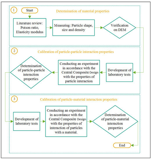
Figure 1.
Strategy to calibrate interaction properties.
2.1. Determination of the Shape, Size, and Density of the Granular Fertilizer
Choosing the appropriate particle size and shape is a critical part of the calibration process due to the substantial influence on the macro response of the bulk material. The particle shape influences the rolling coefficient parameters and the computational complexity. A dial caliper was used to measure three orthogonal dimensions of 80 randomly selected granular fertilizer particles [25]. The largest of the three dimensions was designated as the length, the second largest was the width, and the smallest was the thickness. The sphericity of the particles was calculated using the following equation [26]:
where L, W, and T are the length, width, and thickness of the fertilizer granule (mm); is the sphericity of the granule (dimensionless).
In addition to the particle shape, the particle size also significantly influences the macro response [27]. Therefore, a 1000 g sample was used to determine the particle size and distribution using a sieve. The sieve opening diameter was changed from 6 to 1 mm with an interval of 0.5 mm. The granular fertilizer particle size ranged from 1.5 to 5 mm. The experiment was conducted in triplicate, and the results were averaged.
The liquid displacement method was used to determine the density of the granular fertilizer [28]. A cylinder with an inner radius of 47.5 mm and a height of 45 mm was loaded with compound fertilizers, and the weight was determined with an electronic scale (accuracy of 0.01 g). Since granular fertilizers absorb water, a wetting agent (polyethylene glycol tert-octylphenyl ether) was added to the water at a concentration of 1.5 g/L. The wetting agent prevents the granular fertilizer from absorbing water by reducing the surface tension. The water was poured into the cylinder filled with the granular fertilizer and completely covered the granular fertilizer. The volume of the poured water was considered as free space between the granular fertilizer. The density of the granular fertilizer was determined as:
where is the mass of the granular fertilizer in the cylinder, g; is the volume of the cylinder, mm3; is the free space between the granular fertilizer particles, mm3. The granular fertilizer density was 1575 kg m−3. The granular fertilizer density depends on its moisture, which was 2.5%, with a standard deviation of 0.3%. The moisture of the granular fertilizer was measured before each test with a moisture analyzer.
2.2. EDEM Input Parameters
The simulation was carried out in the EDEM software. The values of the material properties used in the Hertz-Mindlin no-slip numerical model for the DEM simulations were obtained from the literature (except for the granular fertilizer density) (Table 1). The values of the shear modulus and the Poisson’s ratio of the granular fertilizer obtained from the literature as the determined granular fertilizer density were identical to our experimental results. The particle size distribution has to be known to determine the particle-particle and particle-material interaction properties because it significantly affects the experimental results. The boundary conditions were not specified, since we were not interested in how the particles behave when leaving the domain. In the Hertz-Mindlin no-slip model the Euler was selected as a time integration method. The Raleigh time-step was 30%. The estimated cell radius of the simulator grid was 3 mm.

Table 1.
Mechanical properties of the materials.
The low, mid and high levels of the interaction coefficients were determined to develop the CCD using the Design-Expert software (Table 2). Choosing the low and high levels is essential. If the range between the minimum and maximum values is large, there may not be a sufficient number of points. If the range is small, some points may be outside of the range. In this study, the range was not large to ensure accurate calibration results. In this research, low and high levels were chosen according to pre-provided simulations in the DEM.

Table 2.
The levels of the interaction properties.
In the CCD, twenty configurations of the interaction properties were generated for the EDEM simulation using the sandglass test with three factors: the interparticle static friction coefficient (A), the interparticle rolling friction coefficient (B), and the interparticle restitution coefficient (C). The particle-material interaction parameters, i.e., the particle-material static friction coefficient (D), the particle-material rolling friction coefficient (E), and the particle-material restitution coefficient (F), were kept at the mid-levels. The interparticle interaction properties calibrated by the sandglass test were used to calibrate the particle-material interaction properties of the discharge-drop test. In the CCD, twenty configurations of the interaction parameters were generated for the EDEM simulation using the discharge-drop test with three factors: the particle-material static friction coefficient (D), the particle-material rolling friction coefficient (E), and the particle-material restitution coefficient (F). The optimization of the interaction properties according to the simulation results was conducted using the Design-Expert software.
2.3. Sandglass Test
2.3.1. Sandglass Test Process
The sandglass test was used with some modifications that did not take into account the particle-material interaction properties due to design (Figure 2). First, a hole in the center of the bottom of the upper vessel (1) was surrounded by a ring with the same internal radius, with a height of 5 mm. The ring was added to prevent the bottom layer of granular fertilizers from moving when in contact with the material. The top of the ring was tilted outward at 45°. Second, the upper part of the inner vessel (4), which was attached to the cylinder (3) by a micro load cell (5), was tilted inward at 45° to prevent particles from interacting with the material. Therefore, the interaction of particles with material in the upper vessel and in the inner vessel was neglected, since the bottom was filled with immobile particles. Left and right plugs (2) were used to close the central hole of the upper vessel (1).
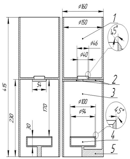
Figure 2.
Sandglass test: (1) Upper vessel with a hole in the center of the bottom; (2) left and right plugs; (3) cylinder; (4) inner vessel; (5) micro load cell.
In the EDEM software, forty thousand particles were generated in the upper vessel in 4 s (Figure 3a). The particles did not move until the left and right plugs were removed at a speed of 0.5 m/s, opening the hole in the center (Figure 3b). The opening speed was 0.5 m/s because this was the speed of removing the plugs by hand in experiments, as determined by a high-speed camera. The particles were discharged from the upper vessel through the hole in the center and filled the inner vessel, and excess particles fell downward (Figure 3c,d).
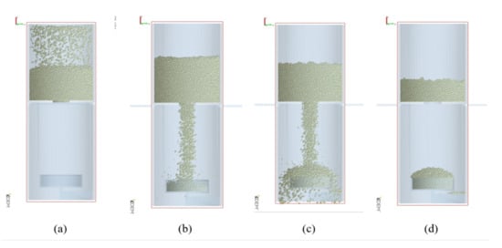
Figure 3.
Working process of the sandglass test in EDEM: (a) Generating granular particles in the upper vessel; (b) coming out of the left and right plugs and filling the inner vessel; (c) falling of excess particles; (d) discharged upper vessel and particle flow formation onto the inner vessel.
The sandglass test was designed to investigate the effect of the particle-particle interaction parameters on the responses, such as the discharge mass (DM) and the discharge time (DT) of the granular fertilizers from the upper vessel, and the AOR and the height (H) of the conical granular fertilizer pile. The sandglass test was repeated five times, and the simulations with the different configurations of the interaction properties were conducted once. The average of the five tests was the target value for the calibration of the EDEM interaction parameters.
2.3.2. Measurement of the Discharge Mass of the Granular Fertilizer
The DM of the granular fertilizer was calculated by subtracting the final weight from the original weight. The original mass of the forty thousand particles simulated in EDEM in the upper vessel was 1837 g. Therefore, 1837 g of the granular fertilizer was loaded into the upper vessel in the real experiments. After discharging the granular fertilizer by removing the left and right plugs, the plugs were closed, and the granular fertilizer mass left in the upper vessel was weighed (Figure 3d). The average of five replicates was the target DM of the granular fertilizer for calibration of the interparticle properties. The fertilizer weight was measured with an electronic scale with an accuracy of 0.01 g.
2.3.3. Measurement of the Discharge Time of the Granular Fertilizer
The DT was measured using two methods, i.e., using a micro load cell (4) and a high-speed video camera (5). The results of the two methods were compared (Figure 4). In the first method, the inner vessel (7) was connected to a micro load cell (4), which sent an analog signal to the Arduino Uno board (2) through the HX711 load cell amplifier (3). The Arduino Uno board converted the analog signal to a digital signal and sent the data to the serial monitor of the laptop (1), where the data and received data time were stored and later were processed to determine the DT. The data in the monitor was zero when the right and left plugs blocked the central orifice of the upper vessel. The measurement time started when the right (9) and left plugs (10) were removed, and the granular fertilizers started to fall into the inner acrylic vessel (7). The measurement time ended when the granular fertilizer stopped discharging from the upper vessel. The data in the monitor were fluctuating when the particles were falling dawn and were constant when the particles stopped falling. The time when the data was fluctuating was considered the DT. In the second method, as all pieces of the equipment (6–11) were acrylic, the discharge process could be monitored using a high-speed video camera (5), which captured images with an exposure time of less than 1000 s−1. After recording, the images could be played back in slow motion, frame by frame. The measurement time started when the granular fertilizer began to discharge from the upper vessel and ended when the last granular fertilizer particle had left the upper vessel. The time between the start time and finish time was considered the DT. The DT results obtained from the load cell and the high-speed video camera were compared. The average of five replicates was considered the target value of the granular fertilizer’s DT to calibrate the interparticle properties.
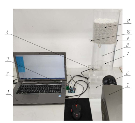
Figure 4.
Granular fertilizer discharge time (DT) measurement of the sandglass test: (1) Laptop; (2) Arduino Uno board; (3) HX711 load cell amplifier; (4) micro load cell; (5) high-speed video camera; (6) bottom vessel; (7) inner vessel; (8) cylinder; (9) right plug; (10) left plug; (11) upper vessel.
2.3.4. Measurement of the Angle of Repose of the Conical Granular Fertilizer Pile
Images of the four sides of the vessel were captured to determine the AOR of the pile in Cartesian coordinates (Figure 5a). It was determined that the area from 20 to 50 mm from the edge best described the AOR of the conical granular fertilizer pile in the inner vessel. Therefore, sample points in this area were randomly chosen in the images and linearly fitted to determine the AOR of the pile (Figure 5b). The results showed that the area of interest for obtaining the AOR was located at a distance of up to 30 mm from the edge of the vessel since it provided the best linear regression results. It should be noted that linear regression depends on the number of points sampled along the border. In this study, the number of sampling points was considered sufficient because the distance between the sampling points was 0.05 mm; thus, the slope of the line represents the AOR of the particle pile (Figure 6). It should be noted that all the conditions to determine the AOR were identical.
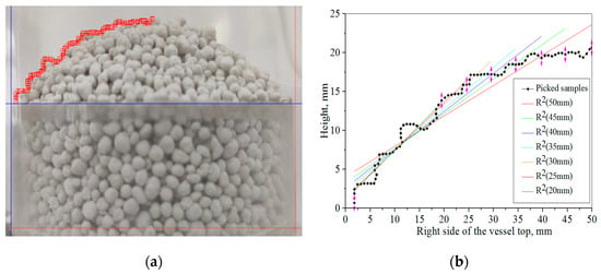
Figure 5.
Measuring the angle of repose (AOR) of the conical granular fertilizer pile: (a) Image digitalization in the Cartesian Coordinate System; (b) linear fitting of the sampled points.
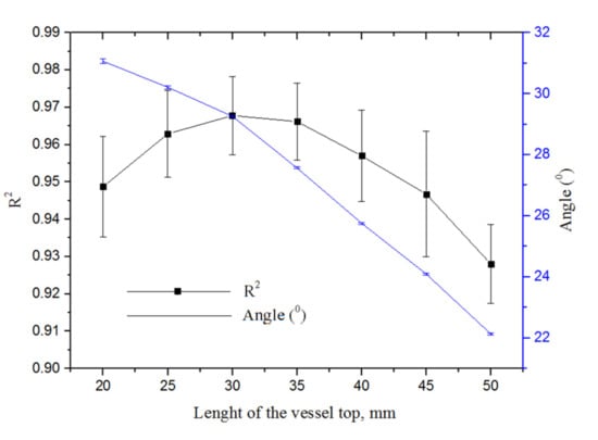
Figure 6.
Results of the linear fitting and angle between fitted line and horizontal axis according to the various length of the inner vessel top.
Since the experiment was repeated five times and the pictures were taken from four sides, the average of twenty values of the AOR in the experiment was considered the target value to calibrate the interparticle interaction properties.
2.3.5. Measurement of the Height of the Conical Granular Fertilizer Pile
The five highest points from the top of the vessel were measured in Cartesian coordinates, and the average was used as the height of the pile (Figure 7). The average was considered the target H of the conical granular fertilizer pile for calibration of the interparticle properties.
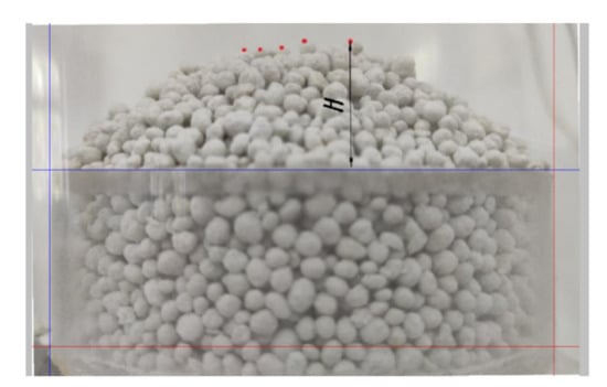
Figure 7.
Measurement of the top five points of the conical granular fertilizer pile in the inner vessel in Cartesian coordinates.
2.4. Discharge-Drop Test
2.4.1. Discharge-Drop Test Process
The discharge-drop test was used to calibrate the particle-material interactions. The discharge-drop test equipment consisted of a container (1), drum (2), plug (3), collision plate (4), and collision plate attachment (5) located between the two acrylic plates (Figure 8). The distance between the two acrylic plates was 50 mm. All the parts were acrylic and were attached to each other, except for the plug, drum, and collision plate attachment. The collision plate attachment was tilted 30 degrees from the horizontal. The drum and the collision plate can be made from various materials. In this research, polylactic acid (PLA) and acrylic were compared. The PLA drum and PLA collision plates were printed with a 3D printer, and the acrylic drum and acrylic collision plate were cut from an acrylic tube and acrylic board, respectively. The drum rotated clockwise at 10 rpm. The plug moved upward and downward, opening and closing the rectangular hole between the container and drum.
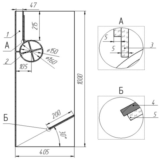
Figure 8.
Discharge-drop test: (1) Container; (2) drum; (3) plug; (4) collision plate; (5) collision plate attachment.
2.4.2. Measuring the Discharge Time of the Granular Fertilizer
When measuring the DT, the high-speed camera was filming the upper left side of the discharge-drop test. The plug was closed when the container was empty (Figure 9a) and was filled with 1640 g of granular fertilizer particles. In the EDEM, 35,800 particles were generated in the container to obtain a mass of 1640 g (Figure 9b). Before the drum started to rotate, the plug was opened (Figure 9c). In a real experiment, the plug was removed manually, and the opening speed did not affect the results of the experiment. In the EDEM, the plug was moved upward until the open hole was free. The drum started to rotate at 10 rpm, discharging the particles (Figure 9d). The DT started when the drum began to turn and ended when the level of the discharged granular fertilizer reached the open hole (Figure 9e). In a real experiment, the moment when the discharged granular fertilizer reached the open hole could be monitored using a high-speed camera. The discharged granular fertilizer exiting the rotating drum fell by gravity onto the collision plate. The use of a fertilizer granular discharge drum to calibrate particle-material interaction properties is a novelty in this study.
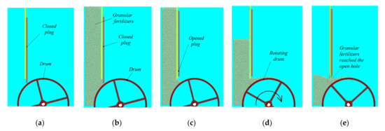
Figure 9.
Discharge process of the discharge-drop test: (a) Free container; (b) filled container; (c) opened plug; (d) particle discharge due to drum rotation; (e) discharged particles reached the open hole.
2.4.3. Measuring the Collision Height
The discharged particles fell and collided with the inclined plate. The highest collision heights (CH) were measured. The average of the measured 36 highest collision heights (CH) was considered the target value to calibrate the particle-material interaction properties (Figure 10). The advantages of using an inclined plate allow us to measure the height of the collision, since particles that collide with the collision plate bounce in one direction.
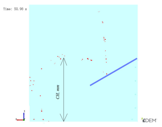
Figure 10.
Measurement of the highest collision heights of the collided granular fertilizers of the discharge-drop test.
3. Results and Discussion
3.1. Verification of the Shape, Size, and Density of the Granular Fertilizer Particles
Since the sphericity of the fertilizer granules exceeded 0.90, the particles created in EDEM were simplified as spheres. Nine spherical particles with various sizes were generated in the EDEM according to the sieve results. The particle size was normally distributed, and the proportion of the nine particles was 0.1, 0.8, 1.7, 19, 26, 30, 16, 6, and 0.4%, and the sizes were 1,1.5, 2, 2.5, 3, 3.5, 4, 4.5, and 5 mm, respectively (Figure 11). The sieve opening diameter ranged from 1 to 6 mm with an interval of 0.5 mm. All granular fertilizer particles larger than the sieve opening diameter were considered to be equal to the sieve opening diameter. The diameter ranged from less than 5.5 mm to more than 1 mm. The size distribution, size, and density of the particles were validated by comparing the mass of the granular fertilizer particles in the vessel and that in the EDEM simulation for an identical vessel. The validation result showed that the difference did not exceed 2 g; thus, it was determined that the density, size, and size distribution of the granular fertilizer particles were adequate for further calibration of the interaction properties.
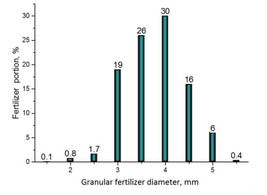
Figure 11.
The size distribution of the granular fertilizer generated on EDEM.
3.2. Results of the Sandglass Test for Calibrating the Particle-Particle Interaction Properties
The results of the sandglass test are listed in Table 3. The average of five replications was considered the target to optimize the particle-particle interaction properties in the Design-Expert software. The targets of the DM, the DT from the upper hopper, the AOR of the conical fertilizer pile in the inner vessel, and the CH of the conical fertilizer pile in the inner vessel were 1285 g, 7 s, 29.26 degrees, and 20.96 mm, respectively. The EDEM simulation results of the sandglass test according to the CCD for the 20 configurations of the particle-particle interaction properties are listed in Table 4. Statistical analysis was performed on the output values of the DM, DT, AOR, and H (Table 5). The results showed that A and B were significant factors affecting the DM, DT, AOR, and CH, and C was a significant factor for CH. The statistical models were significant at p < 0.01. It was determined that H and AOR had the most influences on the response because all three coefficients were significant and close to significant. The reason was that the height between the upper vessel and the inner vessel was sufficient so that the falling speed of the particles depended on the mass, influencing the location of the previously fallen particles. There were no free hits between the granular fertilizer particles in the upper vessel, or they could be neglected; therefore, the restitution coefficient was marginally affected.

Table 3.
The results of the sandglass test.

Table 4.
EDEM simulation results of the particle-particle interaction properties using the sandglass test.

Table 5.
Analysis of variance of the results of the sandglass test.
The following equations with the significant factors were used to predict the response for the given levels of the factors:
Significant interactions between the factors included in Equations (3)–(6) are demonstrated in Figure 12, Figure 13 and Figure 14. When the coefficient of static friction (A) and the coefficient of rolling friction increased, the DM of the granular fertilizer from the upper vessel decreased (Figure 12). The reason is that more particles left the upper vessel. As the interparticle friction coefficients continued to increase, the particles were blocked in the upper vessel, which occurred when determining the high levels of the interaction properties.
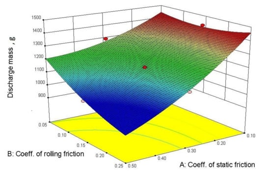
Figure 12.
Response surface of the discharge mass versus the AB interaction.
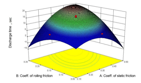
Figure 13.
Response surface of the DT versus the AB interaction.
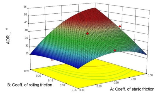
Figure 14.
Response surface of the AOR versus the AB interaction.
The DT of the particles from the upper vessel increased as the static and rolling friction coefficients increased (Figure 13). The static friction coefficient (A) had a larger influence on the DT than the rolling friction coefficient (B). It should be noted that the DT was not a more accurate response than other responses even though the model was significant (Table 5). The reason is that the number of particles generated in the upper vessel was not sufficient. It is assumed that the results would be more precise if the quantity of the particles generated in the upper vessel was twice that used in this study. However, an increase in the particle quantity would increase the calculation time in the EDEM software. In future studies, it is suggested to decrease the upper vessel’s diameter, increase the outlet hole diameter of the upper vessel, and increase the height of the upper vessel. However, the outlet hole diameter of the upper vessel cannot be too small, otherwise particle blockage may occur, depending on the particle size.
The AOR of the conical particle pile in the inner vessel increased as the static friction coefficients (A), and rolling friction coefficients increased (Figure 14). However, when the rolling friction coefficient (B) was at the minimum, the AOR increased and decreased depending on the static friction coefficient (A). This result might be attributed to the influence of the collision restitution coefficient (C). As the static friction coefficient increased to the maximum, the particles in the inner vessel created counteracted the falling particles, decreasing the AOR of the pile.
The optimization in the Design-Expert software was conducted for all responses and the individual responses. The EDEM simulation results are listed in Table 6. The values (e.g., the static friction coefficient (A)) had a large range (between 0.18 and 0.39) because the H and the AOR provided better responses for calibrating the restitution coefficient, whereas the DM and the DT provided better responses for calibrating the static and rolling friction coefficients. This result indicates that the influence of the interaction properties varies. For example, when the granular fertilizer was in the upper vessel, the influence of the rolling and static friction coefficients was larger than that of the restitution coefficient because the granular fertilizer particles were sliding and rotating until they reached the hole in the center. When the granular fertilizer particles left the upper vessel, their speed accelerated and they collided with the other particles after reaching the inner vessel. In this case, the influence of the restitution coefficient was larger than that of the static and rolling friction coefficients. The measured responses listed in Table 6 show that the difference between the coefficients was not substantial. However, each measured response of the corresponding interaction properties optimized by the Design-Expert software was described more precisely than others. For example, the H was the lowest, 21.73 mm, and was close to 20.96 mm. The measured responses for the optimized interaction properties were the second-closest to the target when the four responses were considered together in the Design-Expert software. For example, the H was the second-lowest, 22.46 mm, and was close to 20.96 mm. Therefore, the interaction properties were chosen for the combined responses. The interparticle static friction coefficient (A), the interparticle rolling friction coefficient (B), and the interparticle restitution coefficient (C) of the granular fertilizers were 0.30, 0.05, and 0.58, respectively.

Table 6.
The optimization results for considering all responses and individual responses.
3.3. Results of the Discharge-Drop Test for Calibrating the Particle-Material Interaction Properties
The results of the discharge-drop test are listed in Table 7. The average of five replications was considered the target to calibrate the particle-material interaction properties.

Table 7.
Experimental results of the discharge-drop test.
The simulation results of the discharge-drop test are listed in Table 8. Statistical analysis was performed on the output values of the DT and the CH. The results showed that the particle-material static friction coefficient (D) had a significant effect on the DT, and the particle-material coefficient of restitution (F) significantly affected the CH (Table 9). The statistical models were significant at p < 0.01. The particle-material rolling friction coefficient (E) did not have a significant influence on the results, indicating that the discharge-drop test can be used to calibrate the particle-material static friction coefficient. Calibrating the particle-material properties using the discharge-drop test is accurate, but the simulation in EDEM requires a long time. Calibrating the particle-material restitution coefficients (F) from the particle-material static (D) and rolling friction coefficients (E) could be performed separately because they had no significant influence. Therefore, the discharge test and the drop test can be used to calibrate particle-material interactions.

Table 8.
Simulation results of the discharge-drop test.

Table 9.
ANOVA of the results of the discharge-drop test.
The following equations with the significant factors were used to predict the response for the given levels of the factors:
The equations indicate no interactions between the factors, and the particle-material rolling friction coefficient (E) has a negligible influence on the DT. First of all, this is an ideal situation for calibrating the static friction between particles and material because only one interaction property was significant, and the other interaction properties were not. However, we have to determine the particle-material rolling friction coefficient (E). The negligible influence of the rolling friction between the granular fertilizer particles and various materials has been attributed to the particle shape of the granular fertilizer. The granular fertilizer’s sphericity exceeded 0.90 in this study. It is assumed that the rolling friction coefficient may be significant if the sphericity is less than 0.90. Nevertheless, we can use the parameter obtained from the Design-Expert software because the static friction coefficient depends on the rolling friction coefficient.
The optimization results of the experiments with the PLA and acrylic materials are listed in Table 10. The differences between the interaction properties of the materials were not substantial. It is assumed that the reason was the sphericity of the fertilizers simulated in the EDEM. If the particle shapes were not spherical, the difference would likely be larger.

Table 10.
The optimization results of the experiments.
4. Conclusions and Prospects
The granular fertilizers’ physical properties were determined using experiments and EDEM simulations. After validating the shape of the granular fertilizer particles, the interaction properties were calibrated. The shape of the granular fertilizers simulated in the DEM were spherical. In this study, two laboratory tests (the sandglass test and the discharge-drop test) were developed to simplify the calibration strategy of the particle-particle and particle-material interaction properties of the granular fertilizer particles. Based on the calibration results, it is possible to simulate the interaction of granular fertilizers with various devices. The sandglass test responses showed that the AOR and the H of the pile were suitable to calibrate the particle-particle interaction parameters. However, we assume that the DT would also be significant if the upper vessel was higher. A comparison with the discharge-drop test responses showed that the particle-material restitution coefficients could be calibrated separately from the particle-material static and rolling friction coefficients because they did not influence each other. Therefore, the discharge test or the drop test can be used independently. The discharge test is an ideal laboratory test to calibrate particle-material static friction property. The discharge-drop test responses showed that the DT and the CH were suitable responses to calibrate the particle-particle interaction parameters. Some interaction parameters were insignificant in this calibration, and the likely reason was that the sphericity of the granular fertilizer particles exceeded 0.90. Therefore, the particle shape has to be assessed accurately in the simulation. Nevertheless, the Design-Expert software results can be used to determine the particle-material rolling friction coefficient in the EDEM because it is dependent on the particle-material static friction coefficient.
Author Contributions
Conceptualization, S.A.; methodology, S.A., G.H.; software, L.B.; valida-tion, M.M., Z.W. and J.Z.; formal analysis, J.Z.; investigation, S.A., Z.N.; resources, J.C.; data cura-tion, J.C.; writing—original draft preparation, S.A.; writing—review and editing, S.A., J.Z.; visu-alization, Z.W.; supervision, J.C.; project administration Z.S., N.S.; funding acquisition, J.C. All authors have read and agreed to the published version of the manuscript.
Funding
This research received no external funding.
Institutional Review Board Statement
Not applicable.
Acknowledgments
The authors appreciate the financial support provided by the National Key Research and Development Program of China [grant number 2018YFD0701102].
Conflicts of Interest
The authors declare no conflict of interest.
References
- Cundall, P.A.; Strack, O.D. A discrete numerical model for granular assemblies. Geotech 1979, 29, 47–65. [Google Scholar] [CrossRef]
- Golshan, S.; Sotudeh-Gharebagh, R.; Zarghami, R.; Mostoufi, N.; Blais, B.; Kuipers, J.A.M. Review and implementation of CFD-DEM applied to chemical process systems. Chem. Eng. Sci. 2020, 221, 115646. [Google Scholar] [CrossRef]
- Boac, J.M.; Casada, M.E.; Maghirang, R.G.; Harner, J.P. Material and interaction properties of selected grains and oilseeds for modeling discrete particles. In Proceedings of the ASABE Annual International Meeting 2009, Reno, Nevada, 21–24 June 2009; p. 1. [Google Scholar]
- Zhu, H.P.; Zhou, Z.Y.; Yang, R.Y.; Yu, A.B. Discrete particle simulation of particulate systems: Theoretical developments. Chem. Eng. Sci. 2007, 62, 3378–3396. [Google Scholar] [CrossRef]
- Roessler, T.; Richter, C.; Katterfeld, A.; Will, F. Development of a standard calibration procedure for the DEM parameters of cohesionless bulk materials—Part I: Solving the problem of ambiguous parameter combinations. Powder Technol. 2019, 343, 803–812. [Google Scholar] [CrossRef]
- Di Renzo, A.; Di Maio, F.P. Comparison of contact-force models for the simulation of collisions in DEM-based granular flow codes. Chem. Eng. Sci. 2004, 59, 525–541. [Google Scholar] [CrossRef]
- Barrios, G.K.P.; de Carvalho, R.M.; Kwade, A.; Tavares, L.M. Contact parameter estimation for DEM simulation of iron ore pellet handling. Powder Technol. 2013, 248, 84–93. [Google Scholar] [CrossRef]
- Ye, F.; Wheeler, C.; Chen, B.; Hu, J.; Chen, K.; Chen, W. Calibration and verification of DEM parameters for dynamic particle flow conditions using a backpropagation neural network. Adv. Powder Technol. 2019, 30, 292–301. [Google Scholar] [CrossRef]
- Coetzee, C.J. Calibration of the discrete element method: Strategies for spherical and non-spherical particles. Powder Technol. 2020, 364, 851–878. [Google Scholar] [CrossRef]
- Antony, S.J.; Kuhn, M.R.; Barton, D.C.; Bland, R. Strength and signature of force networks in axially compacted sphere and non-sphere granular media: Micromechanical investigations. J. Phys. D Appl. Phys. 2005, 38, 3944–3952. [Google Scholar] [CrossRef]
- Cavarretta, I.; O’Sullivan, C.; Ibraim, E.; Lings, M.; Hamlin, S.; Wood, D.M. Characterization of artificial spherical particles for DEM validation studies. Particuology 2012, 10, 209–220. [Google Scholar] [CrossRef]
- Wensrich, C.M.; Katterfeld, A. Rolling friction as a technique for modelling particle shape in DEM. Powder Technol. 2012, 217, 409–417. [Google Scholar] [CrossRef]
- Grima, A.P.; Wypych, P.W. Development and validation of calibration methods for discrete element modelling. Granul. Matter 2011, 13, 127–132. [Google Scholar] [CrossRef] [Green Version]
- Tekeste, M.; Mousaviraad, M.; Rosentrater, K. Discrete Element Model Calibration Using Multi-Responses and Simulation of Corn Flow in a Commercial Grain Auger. Trans. ASABE 2018, 61, 1743–1755. [Google Scholar] [CrossRef]
- Derakhshani, S.M.; Schott, D.L.; Lodewijks, G. Micro–macro properties of quartz sand: Experimental investigation and DEM simulation. Powder Technol. 2015, 269, 127–138. [Google Scholar] [CrossRef]
- Do, H.; Aragón, A.; Schott, D. A calibration framework for discrete element model parameters using genetic algorithms. Adv. Powder Technol. 2018, 29. [Google Scholar] [CrossRef]
- Richter, C.; Rößler, T.; Kunze, G.; Katterfeld, A.; Will, F. Development of a standard calibration procedure for the DEM parameters of cohesionless bulk materials—Part II: Efficient optimization-based calibration. Powder Technol. 2020, 360, 967–976. [Google Scholar] [CrossRef]
- Salehi, H.; Sofia, D.; Schütz, D.; Barletta, D.; Poletto, M. Experiments and simulation of torque in Anton Paar powder cell. Part. Sci. Technol. 2018, 1–12. [Google Scholar] [CrossRef]
- Cabiscol, R.; Finke, J.H.; Kwade, A. Calibration and interpretation of DEM parameters for simulations of cylindrical tablets with multi-sphere approach. Powder Technol. 2018, 327, 232–245. [Google Scholar] [CrossRef]
- Zu, E.X.; Zhou, P.; Jiang, Z.H. Discrete Element Method of Coke Accumulation: Calibration of the Contact Parameter. IFAC-PapersOnLine 2018, 51, 241–245. [Google Scholar] [CrossRef]
- Wei, H.; Zan, L.; Li, Y.; Wang, Z.; Saxén, H.; Yu, Y. Numerical and experimental studies of corn particle properties on the forming of pile. Powder Technol. 2017, 321, 533–543. [Google Scholar] [CrossRef]
- Geer, S.; Bernhardt-Barry, M.; Garboczi, E.; Whiting, J.; Donmez, M. A more efficient method for calibrating discrete element method parameters for simulations of metallic powder used in additive manufacturing. Granul. Matter 2018, 20. [Google Scholar] [CrossRef]
- Xia, R.; Li, B.; Wang, X.; Li, T.; Yang, Z. Measurement and calibration of the discrete element parameters of wet bulk coal. Measurement 2019, 142, 84–95. [Google Scholar] [CrossRef]
- Chen, H.; Xiao, Y.G.; Liu, Y.L.; Shi, Y.S. Effect of Young’s modulus on DEM results regarding transverse mixing of particles within a rotating drum. Powder Technol. 2017, 318, 507–517. [Google Scholar] [CrossRef]
- Nelson, S. Dimensional and density data for seeds of cereal grain and other crops. Trans. ASAE 2002, 45, 165. [Google Scholar] [CrossRef]
- Mohsenin, N.N. Physical Properties of Plant and Animal Materials; Department of Agricultural Engineering, Pennsylvania State University: State College, PA, USA, 1986. [Google Scholar]
- Wang, Y.; Alonso-Marroquin, F.; Xue, S.; Xie, J. Revisiting rolling and sliding in two-dimensional discrete element models. Particuology 2015, 18, 35–41. [Google Scholar] [CrossRef]
- Rabier, F.; Temmerman, M.; Böhm, T.; Hartmann, H.; Daugbjerg Jensen, P.; Rathbauer, J.; Carrasco, J.; Fernández, M. Particle density determination of pellets and briquettes. Biomass Bioenergy 2006, 30, 954–963. [Google Scholar] [CrossRef]
- Ding, S.; Bai, L.; Yao, Y.; Yue, B.; Fu, Z.; Zheng, Z.; Huang, Y. Discrete element modelling (DEM) of fertilizer dual-banding with adjustable rates. Comput. Electron. Agric. 2018, 152, 32–39. [Google Scholar] [CrossRef]
- Marigo, M.; Stitt, E.H. Discrete element method (DEM) for industrial applications: Comments on calibration and validation for the modelling of cylindrical pellets. KONA Powder Part. J. 2015, 32, 236–252. [Google Scholar] [CrossRef] [Green Version]
- Moysey, P.A.; Thompson, M.R. Determining the collision properties of semi-crystalline and amorphous thermoplastics for DEM simulations of solids transport in an extruder. Chem. Eng. Sci. 2007, 62, 3699–3709. [Google Scholar] [CrossRef]
Publisher’s Note: MDPI stays neutral with regard to jurisdictional claims in published maps and institutional affiliations. |
© 2021 by the authors. Licensee MDPI, Basel, Switzerland. This article is an open access article distributed under the terms and conditions of the Creative Commons Attribution (CC BY) license (https://creativecommons.org/licenses/by/4.0/).