Comparison of Skeletal and Dental Changes Obtained from a Tooth-Borne Maxillary Expansion Appliance Compared to the Damon System Assessed through a Digital Volumetric Imaging: A Randomized Clinical Trial
Abstract
1. Introduction
2. Experimental Section
Statistical Analysis
3. Results
4. Discussion
Limitations
5. Conclusions
Author Contributions
Funding
Conflicts of Interest
Appendix A
| Landmark | Coordinate | Mean Difference (T1-T0) | Std. Error | p-Value | 95% Confidence Interval for Difference | |
|---|---|---|---|---|---|---|
| Lower Bound | Upper Bound | |||||
| <Damon Group> | ||||||
| UR6P | x | −0.61 * | 0.23 | 0.009 | −1.07 | −0.15 |
| y | 0.81 * | 0.30 | 0.007 | 0.23 | 1.40 | |
| z | −1.51 * | 0.35 | <0.0001 | −2.20 | −0.82 | |
| UR6R | x | −0.53 * | 0.25 | 0.040 | −1.03 | −0.03 |
| y | 0.95 * | 0.26 | 0.001 | 0.43 | 1.48 | |
| z | −1.56 * | 0.40 | <0.0001 | −2.35 | −0.77 | |
| UR6A | x | 0.35 | 0.31 | 0.259 | −0.26 | 0.95 |
| y | 0.92 * | 0.27 | 0.001 | 0.39 | 1.45 | |
| z | −1.59 * | 0.40 | 0.000 | −2.40 | −0.79 | |
| LR6P | x | 0.63 * | 0.26 | 0.018 | 0.11 | 1.15 |
| y | 1.45 * | 0.44 | 0.002 | 0.56 | 2.33 | |
| z | −1.80 * | 0.34 | <0.0001 | −2.49 | −1.12 | |
| LR6R | x | −0.23 | 0.30 | 0.443 | −0.83 | 0.37 |
| y | 1.24 * | 0.54 | 0.023 | 0.17 | 2.30 | |
| z | −1.64 * | 0.36 | <0.0001 | −2.34 | −0.93 | |
| UR4P | x | −1.15 * | 0.27 | <0.0001 | −1.68 | −0.62 |
| y | 0.82 * | 0.33 | 0.016 | 0.16 | 1.49 | |
| z | −1.78 * | 0.43 | <0.0001 | −2.64 | −0.92 | |
| UR4R | x | 0.46 | 0.27 | 0.090 | −0.07 | 0.98 |
| y | 0.51 | 0.28 | 0.080 | −0.06 | 1.07 | |
| z | −1.99 * | 0.44 | <0.0001 | −2.87 | −1.11 | |
| UR4A | x | 0.22 | 0.26 | 0.408 | −0.31 | 0.74 |
| y | 0.49 | 0.29 | 0.089 | −0.08 | 1.06 | |
| z | −2.00 * | 0.45 | <0.0001 | −2.90 | −1.11 | |
| UL6P | x | 0.36 | 0.24 | 0.133 | −0.11 | 0.83 |
| y | 0.50 | 0.30 | 0.102 | −0.10 | 1.10 | |
| z | −1.36 * | 0.35 | <0.0001 | −2.06 | −0.66 | |
| UL6R | x | 0.26 | 0.24 | 0.287 | −0.22 | 0.73 |
| y | 0.56 * | 0.26 | 0.034 | 0.04 | 1.07 | |
| z | −1.26 * | 0.39 | 0.002 | −2.03 | −0.49 | |
| UL6A | x | −0.35 | 0.24 | 0.148 | −0.83 | 0.13 |
| y | 0.60 * | 0.27 | 0.028 | 0.07 | 1.13 | |
| z | −1.24 * | 0.39 | 0.002 | −2.01 | −0.46 | |
| LL6P | x | −0.24 | 0.25 | 0.352 | −0.73 | 0.26 |
| y | 1.06 * | 0.45 | 0.020 | 0.17 | 1.96 | |
| z | −1.67 * | 0.33 | <0.0001 | −2.33 | −1.02 | |
| LL6R | x | 0.48 | 0.29 | 0.102 | −0.10 | 1.06 |
| y | 0.97 | 0.52 | 0.065 | −0.06 | 2.00 | |
| z | −1.48 * | 0.33 | <0.0001 | −2.12 | −0.83 | |
| UL4P | x | 0.99 * | 0.29 | 0.001 | 0.41 | 1.57 |
| y | 0.56 | 0.35 | 0.114 | −0.14 | 1.26 | |
| z | −1.41 * | 0.43 | 0.002 | −2.27 | −0.55 | |
| UL4R | x | −0.60 * | 0.29 | 0.041 | −1.18 | −0.03 |
| y | 0.56 | 0.30 | 0.066 | −0.04 | 1.16 | |
| z | −1.45 * | 0.44 | 0.001 | −2.32 | −0.58 | |
| UL4A | x | −0.30 | 0.29 | 0.298 | −0.88 | 0.27 |
| y | 0.54 | 0.30 | 0.077 | −0.06 | 1.14 | |
| z | −1.39 * | 0.44 | 0.002 | −2.28 | −0.51 | |
| RGP | x | −0.32 * | 0.14 | 0.029 | −0.60 | −0.03 |
| y | 0.88 * | 0.20 | <0.0001 | 0.48 | 1.28 | |
| z | −0.54 * | 0.25 | 0.032 | −1.03 | −0.05 | |
| LGP | x | 0.16 | 0.14 | 0.254 | −0.12 | 0.45 |
| y | 0.73 * | 0.22 | 0.001 | 0.30 | 1.16 | |
| z | −0.34 | 0.26 | 0.190 | −0.86 | 0.17 | |
| <Hyrax Group> | ||||||
| UR6P | x | −2.97 * | 0.23 | <0.0001 | −3.43 | −2.51 |
| y | 0.15 | 0.30 | 0.609 | −0.44 | 0.74 | |
| z | −1.03 * | 0.35 | 0.004 | −1.72 | −0.34 | |
| UR6R | x | −2.61 * | 0.25 | <0.0001 | −3.11 | −2.11 |
| y | −0.03 | 0.26 | 0.906 | −0.56 | 0.50 | |
| z | −1.48 * | 0.40 | <0.0001 | −2.27 | −0.69 | |
| UR6A | x | −0.94 * | 0.31 | 0.003 | −1.54 | −0.33 |
| y | −0.07 | 0.27 | 0.805 | −0.60 | 0.46 | |
| z | −1.52 * | 0.40 | <0.0001 | −2.33 | −0.72 | |
| LR6P | x | 0.38 | 0.26 | 0.153 | −0.14 | 0.90 |
| y | 1.03 * | 0.44 | 0.023 | 0.14 | 1.91 | |
| z | −1.96 * | 0.34 | <0.0001 | −2.65 | −1.28 | |
| LR6R | x | 0.16 | 0.30 | 0.586 | −0.43 | 0.76 |
| y | 0.93 | 0.54 | 0.086 | −0.14 | 1.99 | |
| z | −1.82 * | 0.36 | <0.0001 | −2.52 | −1.11 | |
| UR4P | x | −2.66 * | 0.27 | <0.0001 | −3.19 | −2.13 |
| y | 0.20 | 0.33 | 0.557 | −0.47 | 0.86 | |
| z | −1.41 * | 0.43 | 0.002 | −2.27 | −0.55 | |
| UR4R | x | −2.55 * | 0.27 | <0.0001 | −3.08 | −2.02 |
| y | −0.02 | 0.28 | 0.950 | −0.58 | 0.55 | |
| z | −1.39 * | 0.44 | 0.002 | −2.27 | −0.51 | |
| UR4A | x | −1.78 * | 0.26 | <0.0001 | −2.30 | −1.26 |
| y | −0.03 | 0.29 | 0.917 | −0.60 | 0.54 | |
| z | −1.41 * | 0.45 | 0.002 | −2.31 | −0.52 | |
| UL6P | x | 3.25 * | 0.24 | <0.0001 | 2.78 | 3.72 |
| y | 0.25 | 0.30 | 0.409 | −0.35 | 0.85 | |
| z | −0.79 * | 0.35 | 0.027 | −1.50 | −0.09 | |
| UL6R | x | 2.47 * | 0.24 | <0.0001 | 2.00 | 2.94 |
| y | −0.05 | 0.26 | 0.859 | −0.56 | 0.47 | |
| z | −1.24 * | 0.39 | 0.002 | −2.01 | −0.47 | |
| UL6A | x | 0.97 * | 0.24 | <0.0001 | 0.49 | 1.44 |
| y | −0.06 | 0.27 | 0.818 | −0.60 | 0.47 | |
| z | −1.16 * | 0.39 | 0.004 | −1.93 | −0.39 | |
| LL6P | x | 0.16 | 0.25 | 0.527 | −0.34 | 0.66 |
| y | 1.11 * | 0.45 | 0.015 | 0.22 | 2.00 | |
| z | −1.67 * | 0.33 | <0.0001 | −2.32 | −1.02 | |
| LL6R | x | 0.27 | 0.29 | 0.353 | −0.31 | 0.85 |
| y | 0.91 | 0.52 | 0.084 | −0.13 | 1.93 | |
| z | −1.40 * | 0.33 | <0.0001 | −2.05 | −0.75 | |
| UL4P | x | 3.33 * | 0.29 | <0.0001 | 2.75 | 3.92 |
| y | 0.38 | 0.35 | 0.284 | −0.32 | 1.08 | |
| z | −1.42 * | 0.43 | 0.001 | −2.28 | −0.56 | |
| UL4R | x | 2.69 * | 0.29 | <0.0001 | 2.11 | 3.26 |
| y | 0.33 | 0.30 | 0.268 | −0.26 | 0.93 | |
| z | −1.35 * | 0.44 | 0.003 | −2.22 | −0.48 | |
| UL4A | x | 2.22 * | 0.29 | <0.0001 | 1.65 | 2.80 |
| y | 0.33 | 0.30 | 0.276 | −0.27 | 0.93 | |
| z | −1.32 * | 0.44 | 0.004 | −2.20 | −0.44 | |
| RGP | x | −0.78 * | 0.14 | <0.0001 | −1.06 | −0.49 |
| y | 0.64 * | 0.20 | 0.002 | 0.24 | 1.04 | |
| z | −1.09 * | 0.25 | <0.0001 | −1.58 | −0.60 | |
| LGP | x | 0.82 * | 0.14 | <0.0001 | 0.53 | 1.10 |
| y | 0.57 * | 0.22 | 0.010 | 0.14 | 0.99 | |
| z | −0.80 * | 0.26 | 0.003 | −1.32 | −0.29 | |
| Landmark | Coordinate | Mean Difference (Damon-Hyrax) | Std. Error | p-Value | 95% Confidence Interval for Difference | |
|---|---|---|---|---|---|---|
| Lower Bound | Upper Bound | |||||
| UR6P | x | 2.36 * | 0.32 | <0.0001 | 1.71 | 3.00 |
| y | 0.66 | 0.42 | 0.116 | −0.17 | 1.49 | |
| z | −0.48 | 0.49 | 0.331 | −1.46 | 0.50 | |
| UR6R | x | 2.09 * | 0.36 | <0.0001 | 1.38 | 2.79 |
| y | 0.98 * | 0.37 | 0.010 | 0.24 | 1.73 | |
| z | −0.08 | 0.56 | 0.892 | −1.19 | 1.04 | |
| UR6A | x | 1.28 * | 0.43 | 0.004 | 0.42 | 2.14 |
| y | 0.99 * | 0.38 | 0.011 | 0.24 | 1.74 | |
| z | −0.07 | 0.57 | 0.900 | −1.21 | 1.07 | |
| LR6P | x | 0.26 | 0.37 | 0.491 | −0.48 | 0.99 |
| y | 0.42 | 0.63 | 0.507 | −0.83 | 1.67 | |
| z | 0.16 | 0.49 | 0.744 | −0.81 | 1.13 | |
| LR6R | x | −0.40 | 0.42 | 0.354 | −1.24 | 0.45 |
| y | 0.31 | 0.76 | 0.686 | −1.20 | 1.81 | |
| z | 0.18 | 0.50 | 0.722 | −0.82 | 1.18 | |
| UR4P | x | 1.51 * | 0.38 | <0.0001 | 0.76 | 2.26 |
| y | 0.63 | 0.47 | 0.189 | −0.31 | 1.57 | |
| z | −0.37 | 0.61 | 0.542 | −1.59 | 0.84 | |
| UR4R | x | 3.01 * | 0.38 | <0.0001 | 2.26 | 3.75 |
| y | 0.52 | 0.40 | 0.197 | −0.28 | 1.32 | |
| z | −0.60 | 0.63 | 0.341 | −1.84 | 0.65 | |
| UR4A | x | 2.00 * | 0.37 | <0.0001 | 1.26 | 2.74 |
| y | 0.52 | 0.40 | 0.200 | −0.28 | 1.32 | |
| z | −0.59 | 0.64 | 0.359 | −1.85 | 0.68 | |
| UL6P | x | −2.89 * | 0.33 | <0.0001 | −3.55 | −2.22 |
| y | 0.25 | 0.43 | 0.562 | −0.60 | 1.10 | |
| z | −0.57 | 0.50 | 0.259 | −1.56 | 0.43 | |
| UL6R | x | −2.21 * | 0.34 | <0.0001 | −2.89 | −1.54 |
| y | 0.60 | 0.37 | 0.104 | −0.13 | 1.33 | |
| z | −0.02 | 0.55 | 0.971 | −1.11 | 1.07 | |
| UL6A | x | −1.32 * | 0.34 | <0.0001 | −2.00 | −0.64 |
| y | 0.66 | 0.38 | 0.085 | −0.09 | 1.42 | |
| z | −0.08 | 0.55 | 0.890 | −1.17 | 1.02 | |
| LL6P | x | −0.39 | 0.35 | 0.270 | −1.10 | 0.31 |
| y | −0.04 | 0.63 | 0.945 | −1.30 | 1.22 | |
| z | −0.01 | 0.46 | 0.988 | −0.93 | 0.92 | |
| LL6R | x | 0.21 | 0.41 | 0.612 | −0.61 | 1.03 |
| y | 0.06 | 0.73 | 0.933 | −1.40 | 1.52 | |
| z | −0.07 | 0.46 | 0.876 | −0.99 | 0.85 | |
| UL4P | x | −2.35 * | 0.42 | <0.0001 | −3.17 | −1.52 |
| y | 0.18 | 0.50 | 0.715 | −0.807 | 1.17 | |
| z | 0.01 | 0.61 | 0.988 | −1.20 | 1.22 | |
| UL4R | x | −3.29 * | 0.41 | <0.0001 | −4.10 | −2.47 |
| y | 0.22 | 0.42 | 0.598 | −0.62 | 1.07 | |
| z | −0.11 | 0.62 | 0.866 | −1.34 | 1.13 | |
| UL4A | x | −2.52 * | 0.41 | <0.0001 | −3.34 | −1.71 |
| y | 0.21 | 0.43 | 0.624 | −0.64 | 1.06 | |
| z | −0.07 | 0.63 | 0.906 | −1.32 | 1.18 | |
| RGP | x | 0.46 * | 0.20 | 0.025 | 0.06 | 0.86 |
| y | 0.24 | 0.28 | 0.404 | −0.33 | 0.80 | |
| z | 0.55 | 0.35 | 0.120 | −0.15 | 1.24 | |
| LGP | x | −0.65 * | 0.20 | 0.002 | −1.05 | −0.25 |
| y | 0.16 | 0.30 | 0.597 | −0.44 | 0.77 | |
| z | 0.46 | 0.37 | 0.216 | −0.27 | 1.19 | |
References
- Lee, K.-J.; Choi, S.-H.; Choi, T.-H.; Shi, K.-K.; Keum, B.-T. Maxillary transverse expansion in adults: Rationale, appliance design, and treatment outcomes. Semin. Orthod. 2018, 24, 52–65. [Google Scholar] [CrossRef]
- Uysal, T.; Memili, B.; Usumez, S.; Sari, Z. Dental and alveolar arch widths in normal occlusion, class II division 1 and class II division 2. Angle Orthod. 2005, 75, 941–947. [Google Scholar] [PubMed]
- Proffit, W.R.; Fields, H.W.; Sarver, D.M. Contemporary Orthodontics, 5th ed.; Elsevier: St. Louis, MO, USA, 2013. [Google Scholar]
- Erverdi, N.; Okar, I.; Kucukkeles, N.; Arbak, S. A comparison of two different rapid palatal expansion techniques from the point of root resorption. Am. J. Orthod. Dentofac. Orthop. 1994, 106, 47–51. [Google Scholar] [CrossRef]
- Odenrick, L.; Karlander, O.D.E.L.; Pierce, O.D.; Fracds, O.D.; Kretschmar, U. Surface resorption following two forms of rapid maxillary expansion. Eur. J. Orthod. 1991, 13, 264–270. [Google Scholar] [CrossRef]
- Işeri, H.; Ozsoy, S. Semirapid maxillary expansion—A study of long-term transverse effects in older adolescents and adults. Angle Orthod. 2004, 74, 71–78. [Google Scholar] [PubMed]
- Asanza, S.; Cisneros, G.J.; Nieberg, L.G. Comparison of Hyrax and bonded expansion appliances. Angle Orthod. 1997, 67, 15–22. [Google Scholar]
- Sarnäs, K.-V.; Björk, A.; Rune, B. Long-term effect of rapid maxillary expansion studied in one patient with the aid of metallic implants and roentgen stereometry. Eur. J. Orthod. 1992, 14, 427–432. [Google Scholar] [CrossRef]
- Dwight, D.M.; Alan, B. DamonSystem: The Workbook; Ormco: Orange, CA, USA, 2005. [Google Scholar]
- Wright, N.; Modarai, F.; Cobourne, M.T.; DiBiase, A.T. Do you do Damon®? What is the current evidence base underlying the philosophy of this appliance system? J. Orthod. 2011, 38, 222–230. [Google Scholar] [CrossRef]
- Damon, D.H. The Damon low-friction bracket: A biologically compatible straight-wire system. J. Clin. Orthod. 1998, 32, 670–680. [Google Scholar]
- Yu, Y.-L.; Tang, G.H.; Gong, F.-F.; Chen, L.-L.; Qian, Y.-F. A comparison of rapid palatal expansion and Damon appliance on non-extraction correction of dental crowding. Shanghai J. Stomatol. 2008, 17, 237–242. [Google Scholar]
- Portney, L.; Watkins, M. Foundations of Clinical Research: Applications to Practice, 2nd ed.; Prentice Hall Health: Upper Saddle River, NJ, USA, 2000. [Google Scholar]
- Vich, M.; Secanell, M.; Major, P.W.; Carey, J. Optimization analysis for plane orientation in 3-dimensional cephalometric analysis of serial cone-beam computerized tomography images. Oral Surg. Oral Med. Oral Pathol. Oral Radiol. Endodontol. 2011, 111, 771–777. [Google Scholar] [CrossRef]
- DeCesare, A.; Secanell, M.; Lagravère, M.; Carey, J. Multiobjective optimization framework for landmark measurement error correction in three-dimensional cephalometric tomography. Dentomaxillofacial Radiol 2013, 42, 20130035. [Google Scholar] [CrossRef] [PubMed]
- Vich, M.; Gordon, J.M.; Guedes, I.H.; Flores-Mir, C.; Carey, J.; Heo, G.; Major, P.W. Reliability of Traditional Cephalometric Landmarks as Seen in Three-Dimensional Analysis in Maxillary Expansion Treatments. Angle Orthod. 2009, 79, 1047–1056. [Google Scholar] [CrossRef]
- Luebbert, J.; Ghoneima, A.; Lagravère, M.O. Skeletal and dental effects of rapid maxillary expansion assessed through three-dimensional imaging: A multicenter study. Int. Orthod. 2016, 14, 15–31. [Google Scholar] [CrossRef] [PubMed]
- Bazargani, F.; Feldmann, I.; Bondemark, L. Three-dimensional analysis of effects of rapid maxillary expansion on facial sutures and bones: A systematic review. Angle Orthod. 2013, 83, 1074–1082. [Google Scholar] [CrossRef] [PubMed]
- Capps, C.J.; Campbell, P.M.; Benson, B.; Buschang, P.H. Can posterior teeth of patients be translated buccally, and does bone form on the buccal surface in response? Angle Orthod 2016, 86, 527–534. [Google Scholar] [CrossRef]
- Kraus, C.D.; Campbell, P.M.; Spears, R.; Taylor, R.W.; Buschang, P.H. Bony adaptation after expansion with light-to-moderate continuous forces. Am. J. Orthod. Dentofac. Orthop. 2014, 145, 655–666. [Google Scholar] [CrossRef]
- Filho, O.G.D.S.; Montes, L.A.D.P.; Torelly, L.F. Rapid maxillary expansion in the deciduous and mixed dentition evaluated through posteroanterior cephalometric analysis. Am. J. Orthod. Dentofac. Orthop. 1995, 107, 268–275. [Google Scholar] [CrossRef]
- Leung, C.C.; Palomo, L.; Griffith, R.; Hans, M.G. Accuracy and reliability of cone-beam computed tomography for measuring alveolar bone height and detecting bony dehiscences and fenestrations. Am. J. Orthod. Dentofac. Orthop. 2010, 137, S109–S119. [Google Scholar] [CrossRef]
- Sun, Z.; Smith, T.; Kortam, S.; Kim, D.-G.; Tee, B.C.; Fields, H. Effect of bone thickness on alveolar bone-height measurements from cone-beam computed tomography images. Am. J. Orthod. Dentofac. Orthop. 2011, 139, e117–e127. [Google Scholar] [CrossRef]
- Ballanti, F.; Lione, R.; Fanucci, E.; Franchi, L.; Baccetti, T.; Cozza, P. Immediate and Post-Retention Effects of Rapid Maxillary Expansion Investigated by Computed Tomography in Growing Patients. Angle Orthod. 2009, 79, 24–29. [Google Scholar] [CrossRef] [PubMed]
| Variable | Group A (Damon) Mean (SD) or n (%) | Group B (Hyrax) Mean (SD) of n (%) | p-Value |
|---|---|---|---|
| Age (y) | 13.8 (1.6) | 13.3 (1.5) | 0.188 |
| Sex | 0.174 | ||
| Male | 13 (31.7%) | 19 (46.3%) | |
| Female | 28 (68.3%) | 22 (53.7%) |
| Acronym | Landmark Full Name | Acronym | Landmark Full Name |
|---|---|---|---|
| UR6P | Upper Right First Molar Pulp Chamber | UL6R | Upper Left First Molar Mesial Root Apex |
| UR6R | Upper Right First Molar Mesial Root Apex | UL6A | Upper Left First Molar Alveolar Bone |
| UR6A | Upper Right First Molar Alveolar Bone | LL6P | Lower Left First Molar Pulp Chamber |
| LR6P | Lower Right First Molar Pulp Chamber | LL6R | Lower Left First Molar Mesial Root Apex |
| LR6R | Lower Right First Molar Mesial Root Apex | UL4P | Upper Left First Premolar Pulp Chamber |
| UR4P | Upper Right First Premolar Pulp Chamber | UL4R | Upper Left First Premolar Root Apex |
| UR4R | Upper Right First Premolar Root Apex | UL4A | Upper Left First Premolar Alveolar Bone |
| UR4A | Upper Right First Premolar Alveolar Bone | UL6P | Upper Left First Molar Pulp Chamber |
| RGP | Right Greater Palatine Foramen | LGP | Left Greater Palatine Foramen |
| Landmark Description | 3D View (Upper Left), Axial View (Upper Right), Sagittal View (Lower Left), Coronal View (Lower Right) |
|---|---|
| Upper First Molar Pulp Chamber =center of largest cross-sectional pulp chamber area | 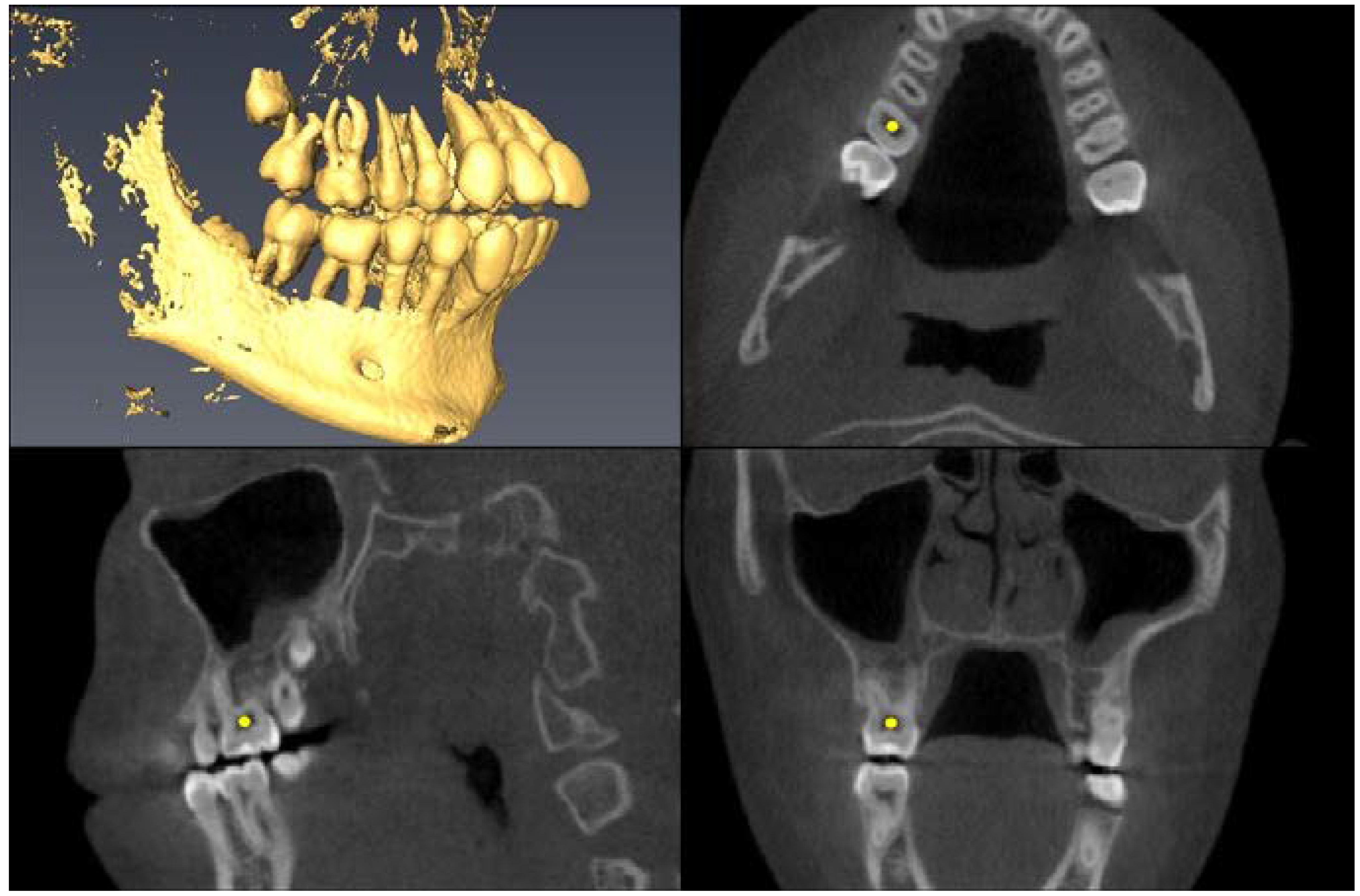 |
| Upper First Molar Mesial Root Apex =apex of mesio-buccal root | 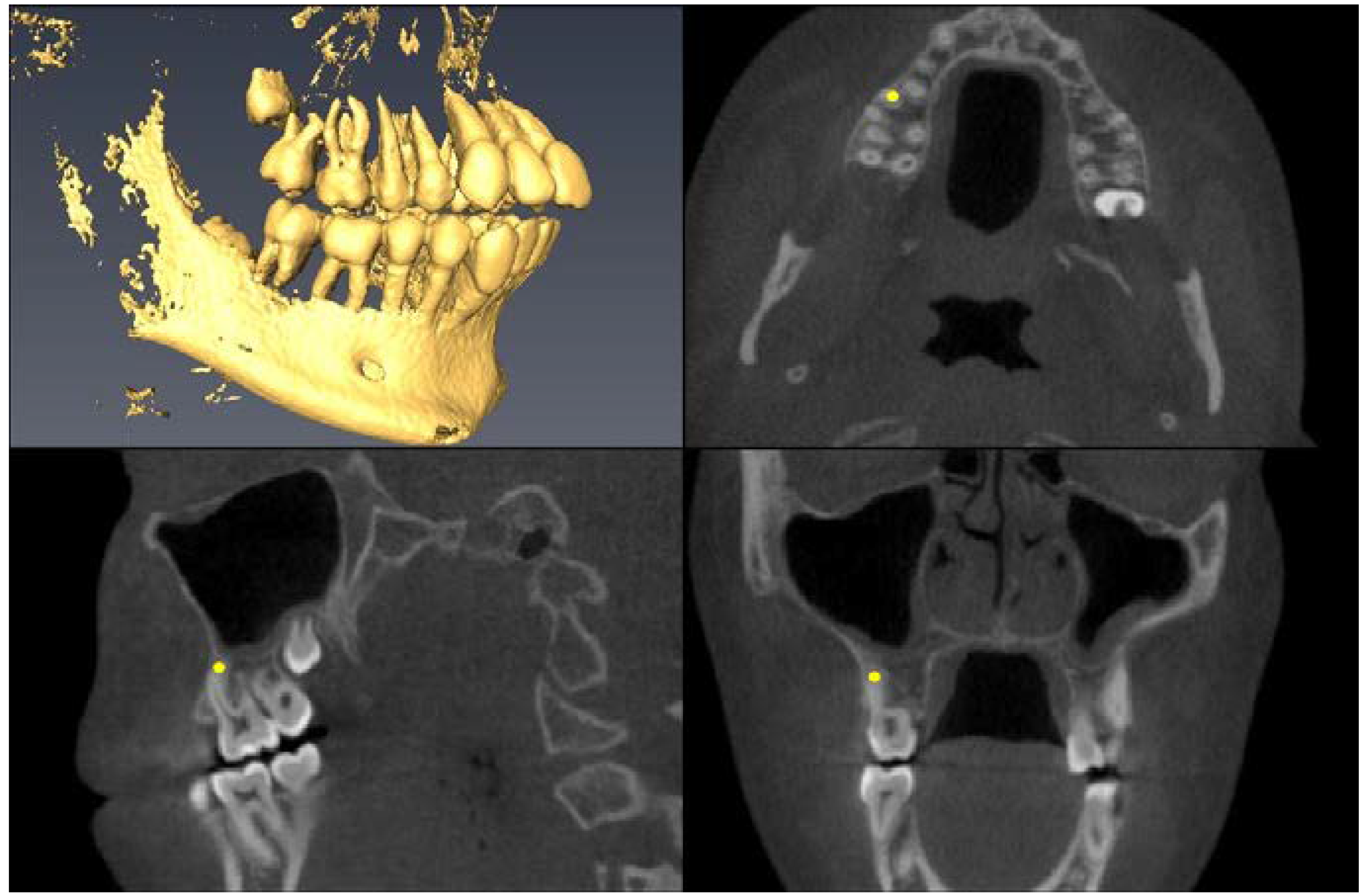 |
| Upper First Molar Alveolar Bone =alveolar bone next to mesial root apex | 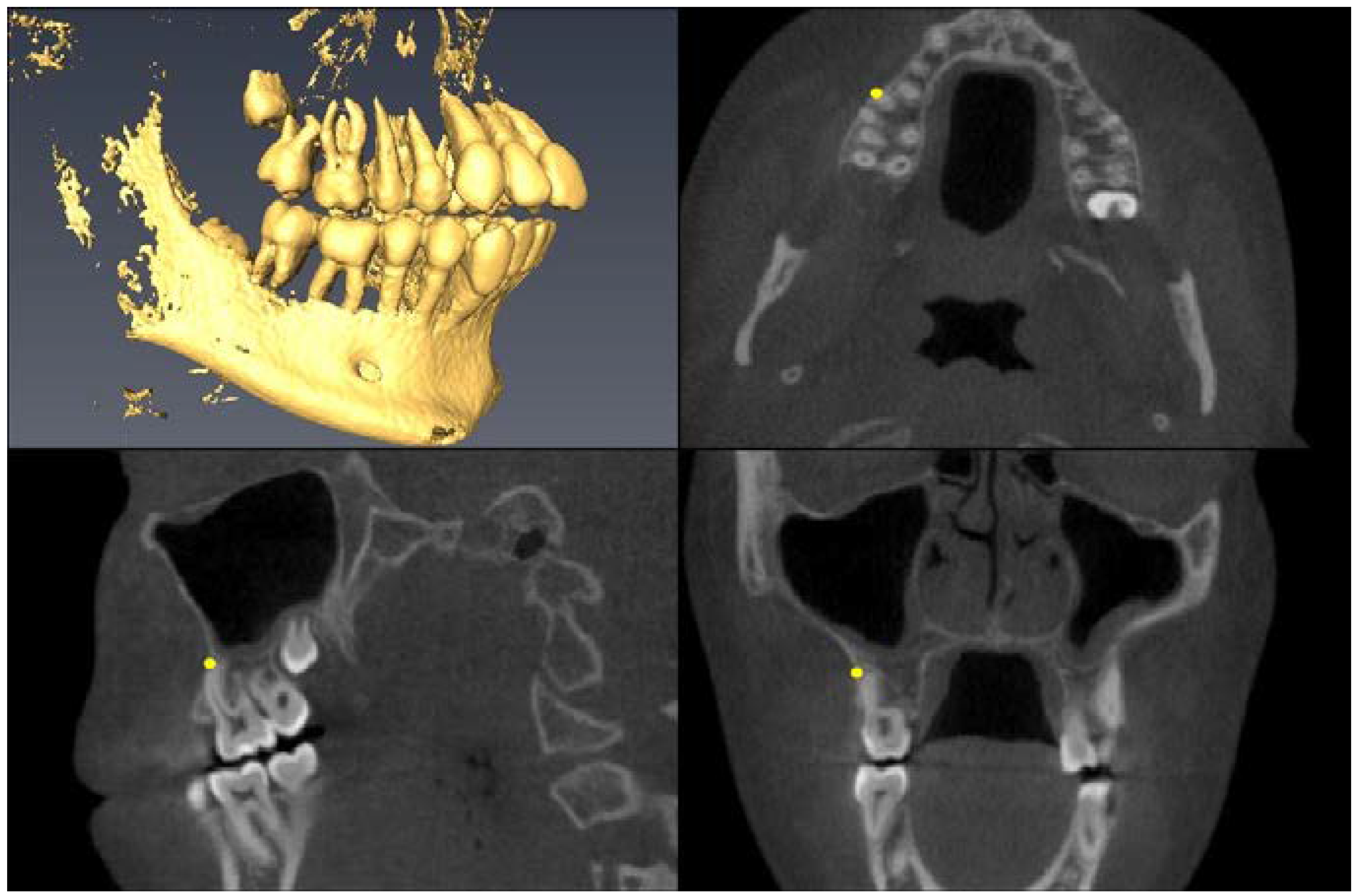 |
| Lower First Molar Pulp Chamber =center of largest cross-sectional pulp chamber area | 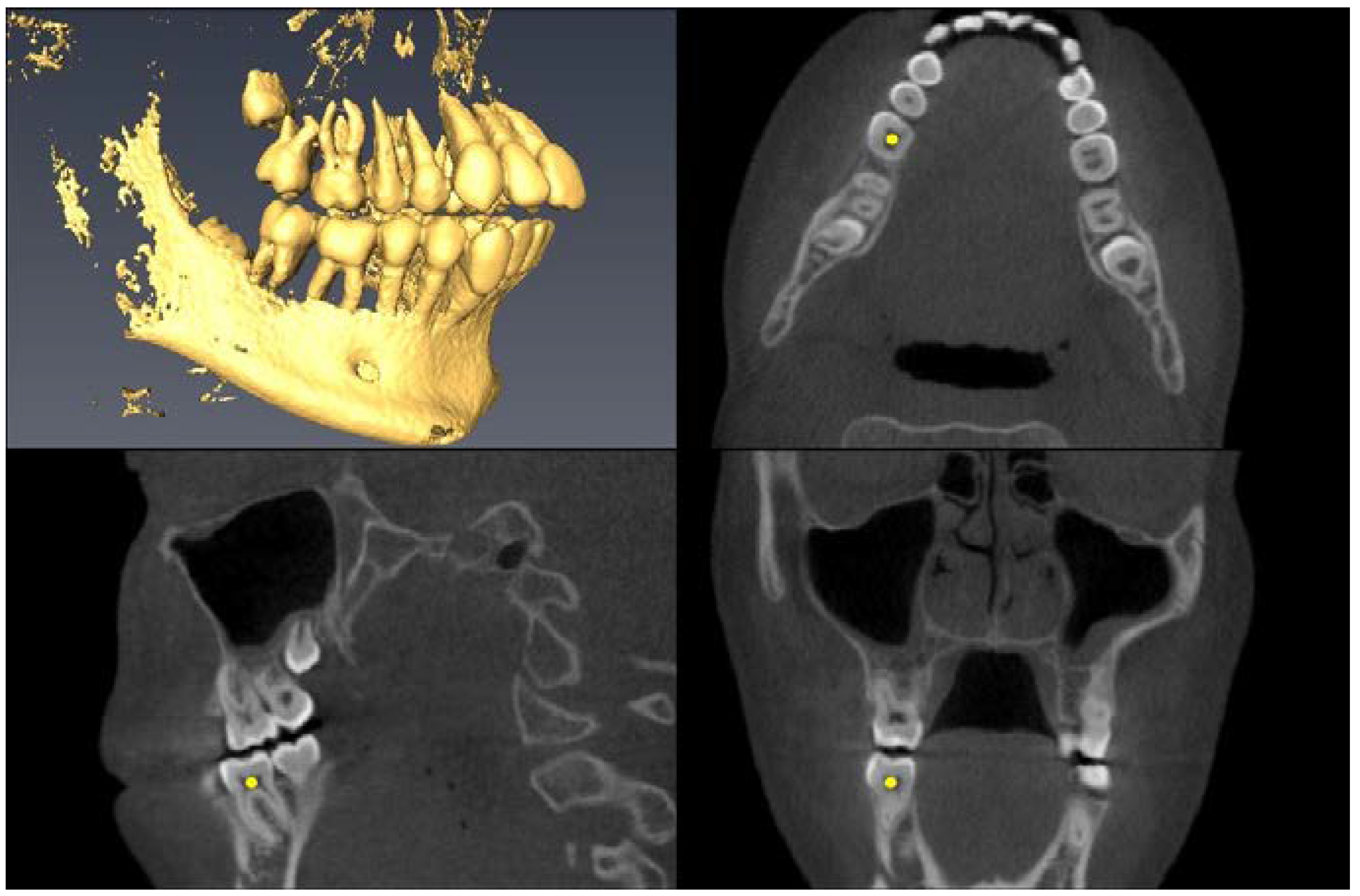 |
| Lower First Molar Mesial Root Apex =apex of mesial root | 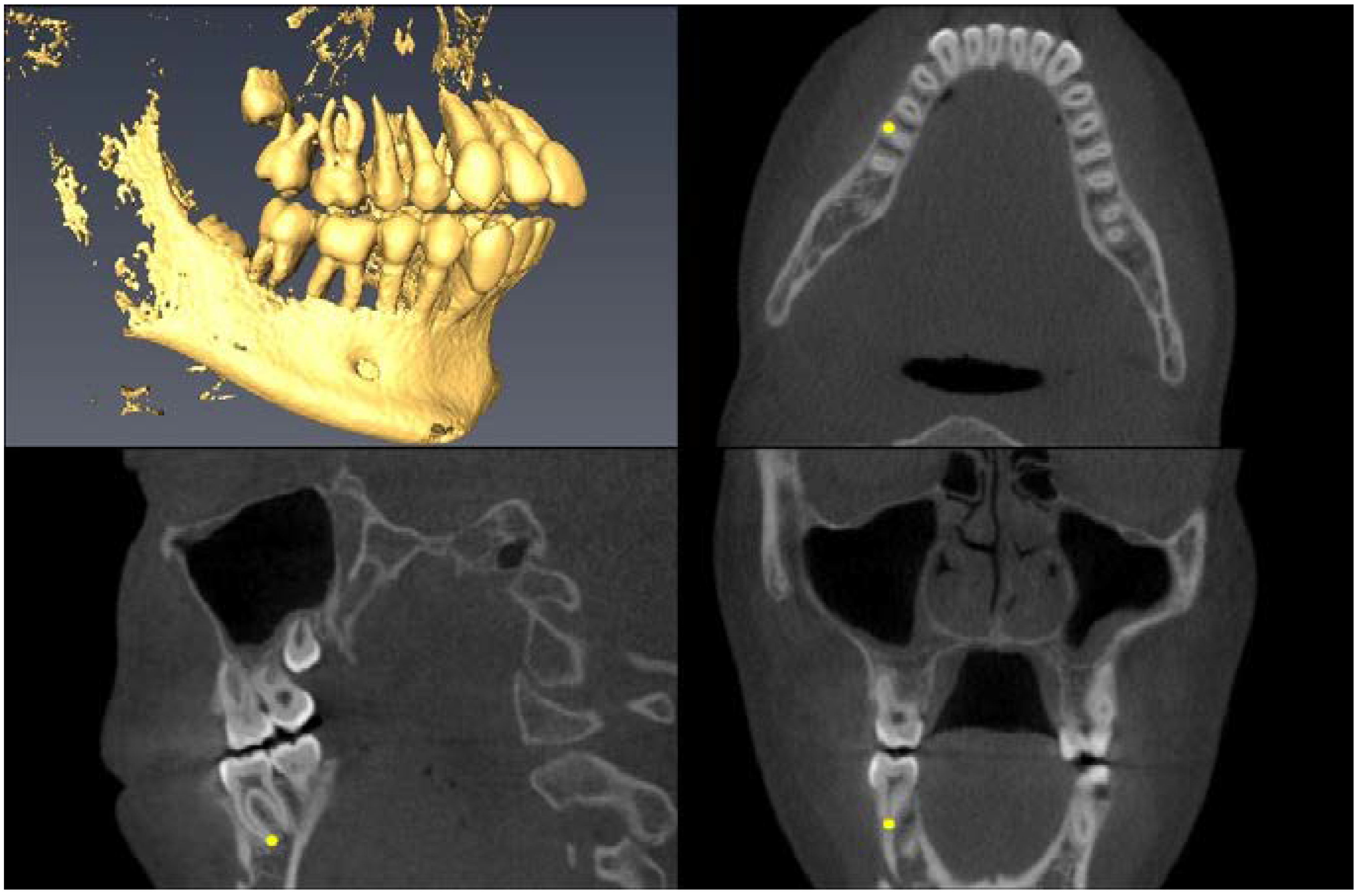 |
| Upper First Premolar Pulp Chamber =center of largest cross-sectional pulp chamber area | 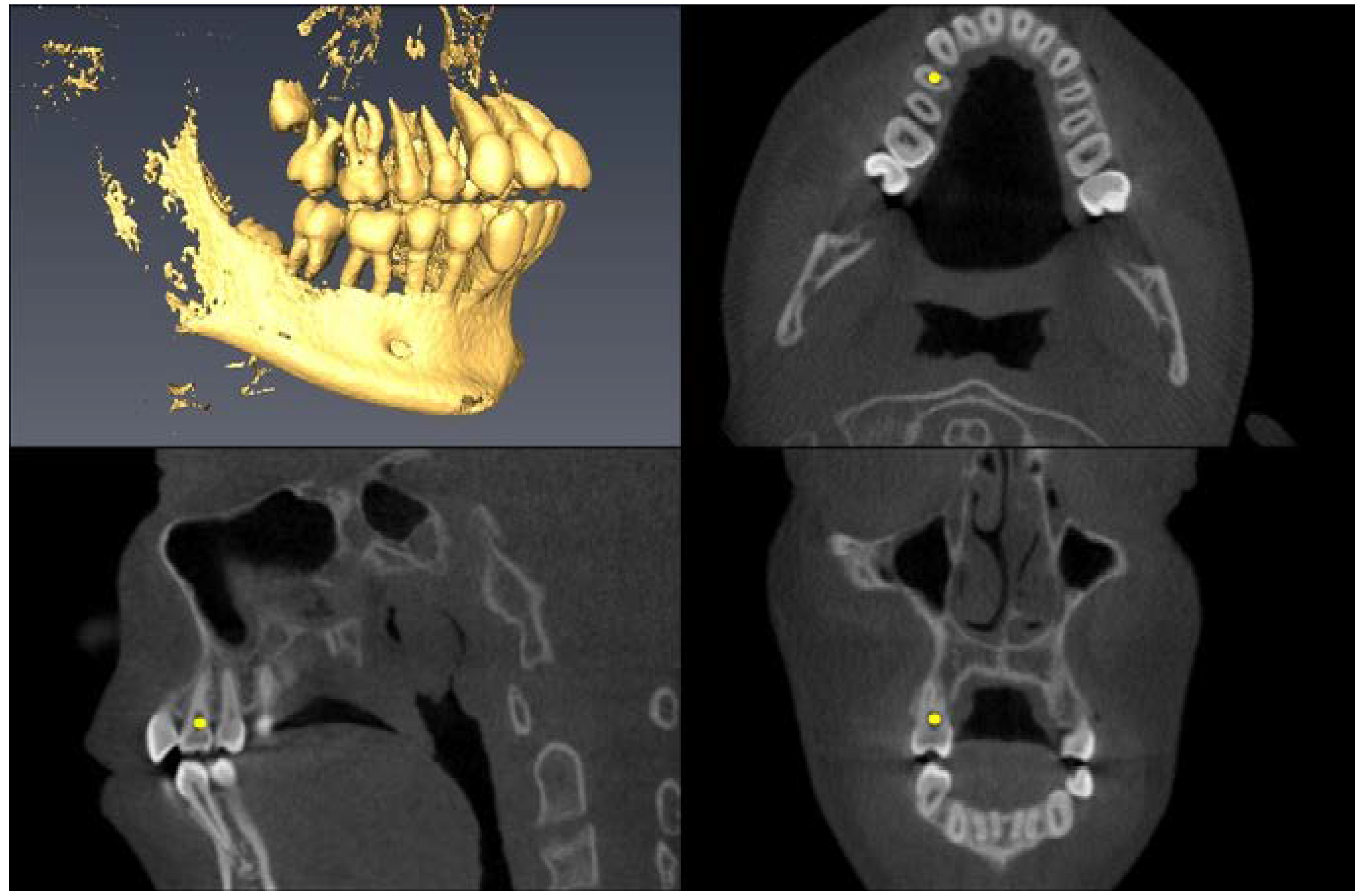 |
| Upper First Premolar Root Apex =apex of mesial root |  |
| Upper First Premolar Alveolar Bone =alveolar bone next to mesial root apex | 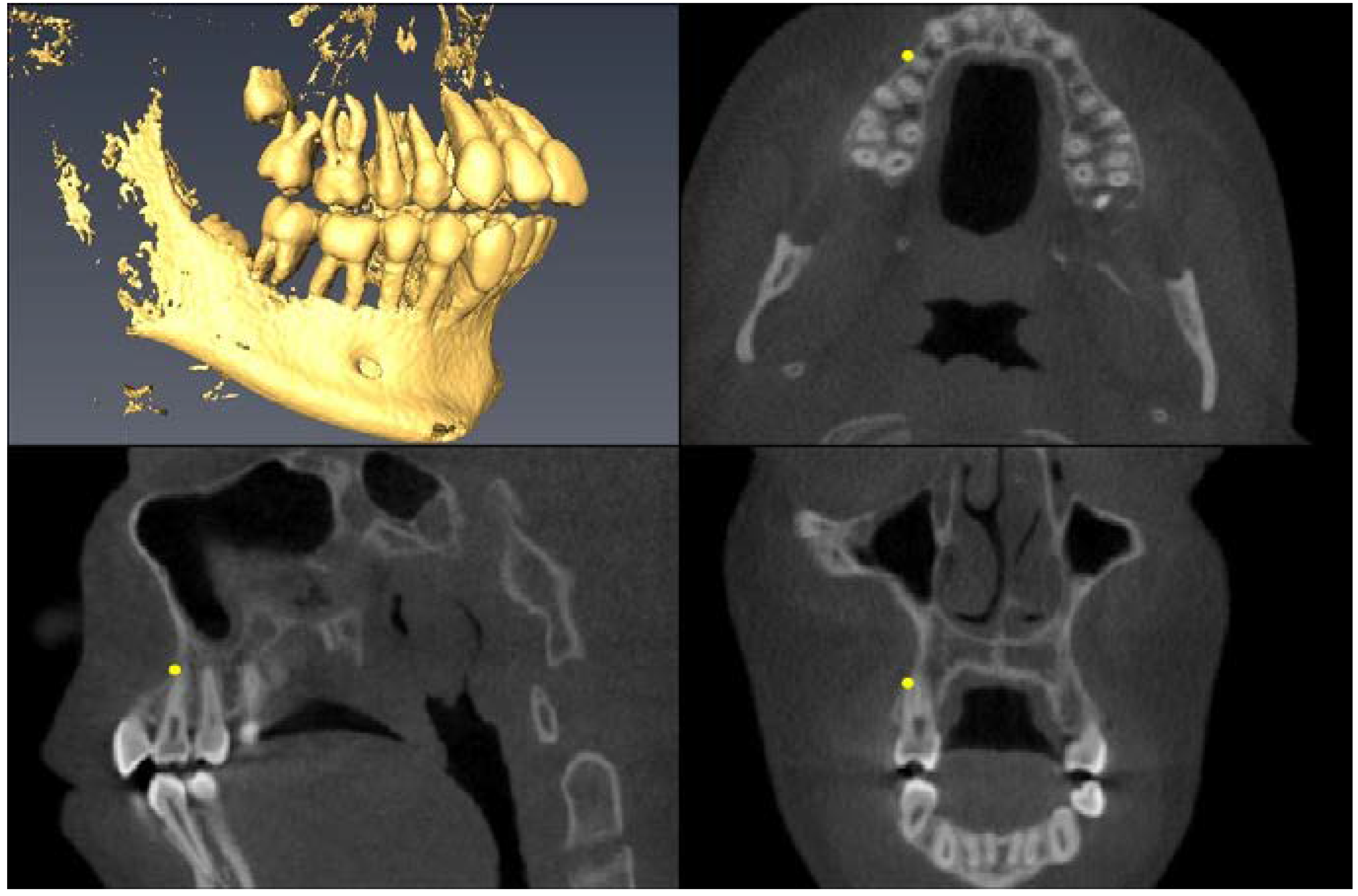 |
| Greater Palatine Foramen =center of largest cross-sectional foramen area |  |
| Landmark | Mean Difference (Damon-Hyrax) | 95% Confidence Interval | Significance | ||
|---|---|---|---|---|---|
| Lower Bound | Upper Bound | p-Value | Clinical (>1 mm) | ||
| Transverse Changes (X coordinate) | |||||
| UR6P | 2.36 | 1.71 | 3.00 | <0.0001 | Yes |
| UR6R | 2.09 | 1.38 | 2.79 | <0.0001 | Yes |
| UR6A | 1.28 | 0.42 | 2.14 | 0.004 | Yes |
| UR4P | 1.51 | 0.76 | 2.26 | <0.0001 | Yes |
| UR4R | 3.01 | 2.26 | 3.75 | <0.0001 | Yes |
| UR4A | 2.00 | 1.26 | 2.74 | <0.0001 | Yes |
| UL6P | −2.89 | −3.55 | −2.22 | <0.0001 | Yes |
| UL6R | −2.21 | −2.89 | −1.54 | <0.0001 | Yes |
| UL6A | −1.32 | −2.00 | −0.64 | <0.0001 | Yes |
| UL4P | −2.35 | −3.17 | −1.52 | <0.0001 | Yes |
| UL4R | −3.29 | −4.10 | −2.47 | <0.0001 | Yes |
| UL4A | −2.52 | −3.34 | −1.71 | <0.0001 | Yes |
| RGP | 0.46 | 0.06 | 0.86 | 0.025 | No |
| LGP | −0.65 | −1.05 | −0.25 | 0.002 | No |
| Anteroposterior Changes (Y coordinate) | |||||
| UR6R | 0.98 | 0.24 | 1.73 | 0.010 | No |
| UR6A | 0.99 | 0.24 | 1.74 | 0.011 | No |
| Vertical Changes (Z coordinate) | |||||
| None | |||||
© 2020 by the authors. Licensee MDPI, Basel, Switzerland. This article is an open access article distributed under the terms and conditions of the Creative Commons Attribution (CC BY) license (http://creativecommons.org/licenses/by/4.0/).
Share and Cite
Nam, H.J.; Gianoni-Capenakas, S.; Major, P.W.; Heo, G.; Lagravère, M.O. Comparison of Skeletal and Dental Changes Obtained from a Tooth-Borne Maxillary Expansion Appliance Compared to the Damon System Assessed through a Digital Volumetric Imaging: A Randomized Clinical Trial. J. Clin. Med. 2020, 9, 3167. https://doi.org/10.3390/jcm9103167
Nam HJ, Gianoni-Capenakas S, Major PW, Heo G, Lagravère MO. Comparison of Skeletal and Dental Changes Obtained from a Tooth-Borne Maxillary Expansion Appliance Compared to the Damon System Assessed through a Digital Volumetric Imaging: A Randomized Clinical Trial. Journal of Clinical Medicine. 2020; 9(10):3167. https://doi.org/10.3390/jcm9103167
Chicago/Turabian StyleNam, Hye Jin, Silvia Gianoni-Capenakas, Paul W. Major, Giseon Heo, and Manuel O. Lagravère. 2020. "Comparison of Skeletal and Dental Changes Obtained from a Tooth-Borne Maxillary Expansion Appliance Compared to the Damon System Assessed through a Digital Volumetric Imaging: A Randomized Clinical Trial" Journal of Clinical Medicine 9, no. 10: 3167. https://doi.org/10.3390/jcm9103167
APA StyleNam, H. J., Gianoni-Capenakas, S., Major, P. W., Heo, G., & Lagravère, M. O. (2020). Comparison of Skeletal and Dental Changes Obtained from a Tooth-Borne Maxillary Expansion Appliance Compared to the Damon System Assessed through a Digital Volumetric Imaging: A Randomized Clinical Trial. Journal of Clinical Medicine, 9(10), 3167. https://doi.org/10.3390/jcm9103167


