
Tongue-in-Groove: A Novel Implant Design for a Blow-Out Fracture

Abstract
1. Introduction
2. Materials and Methods
2.1. Patient Selection
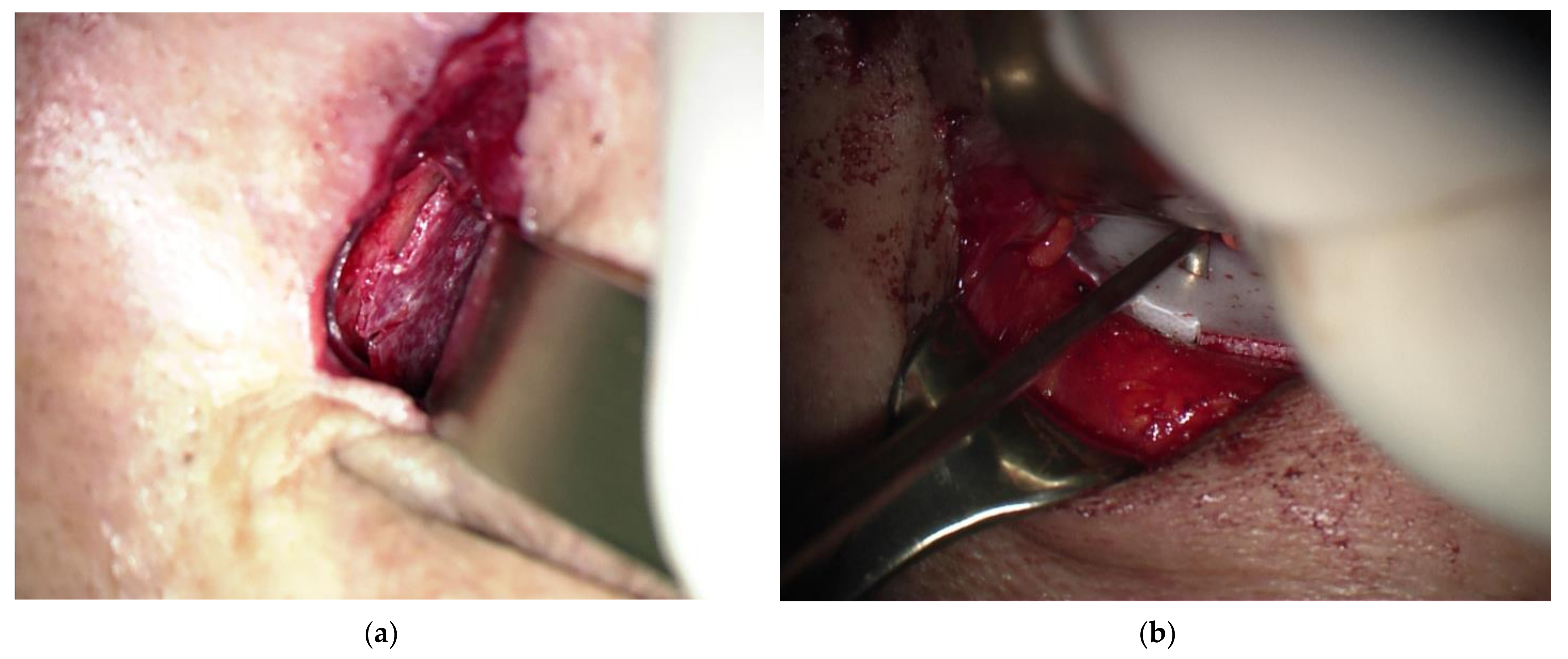
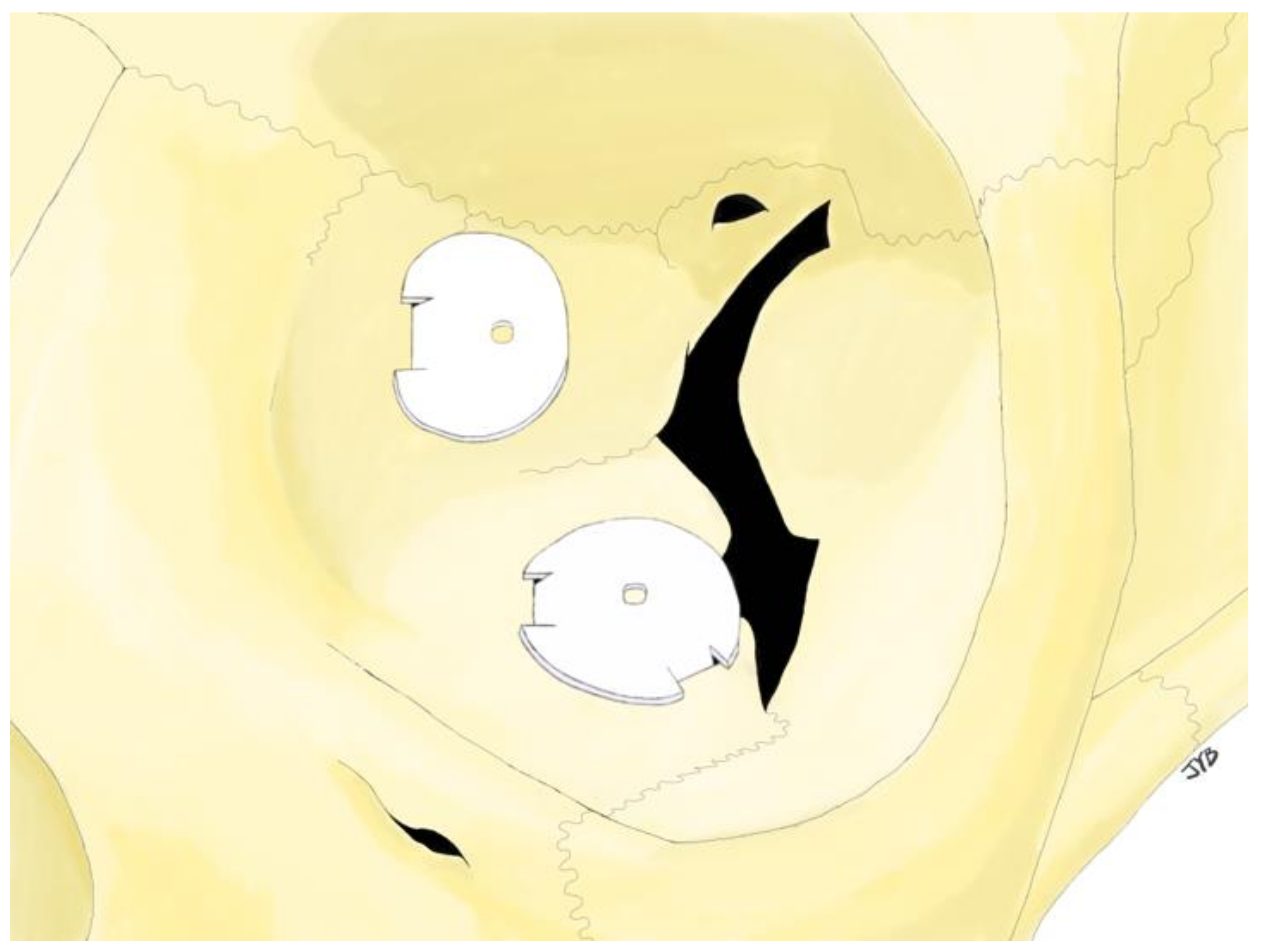
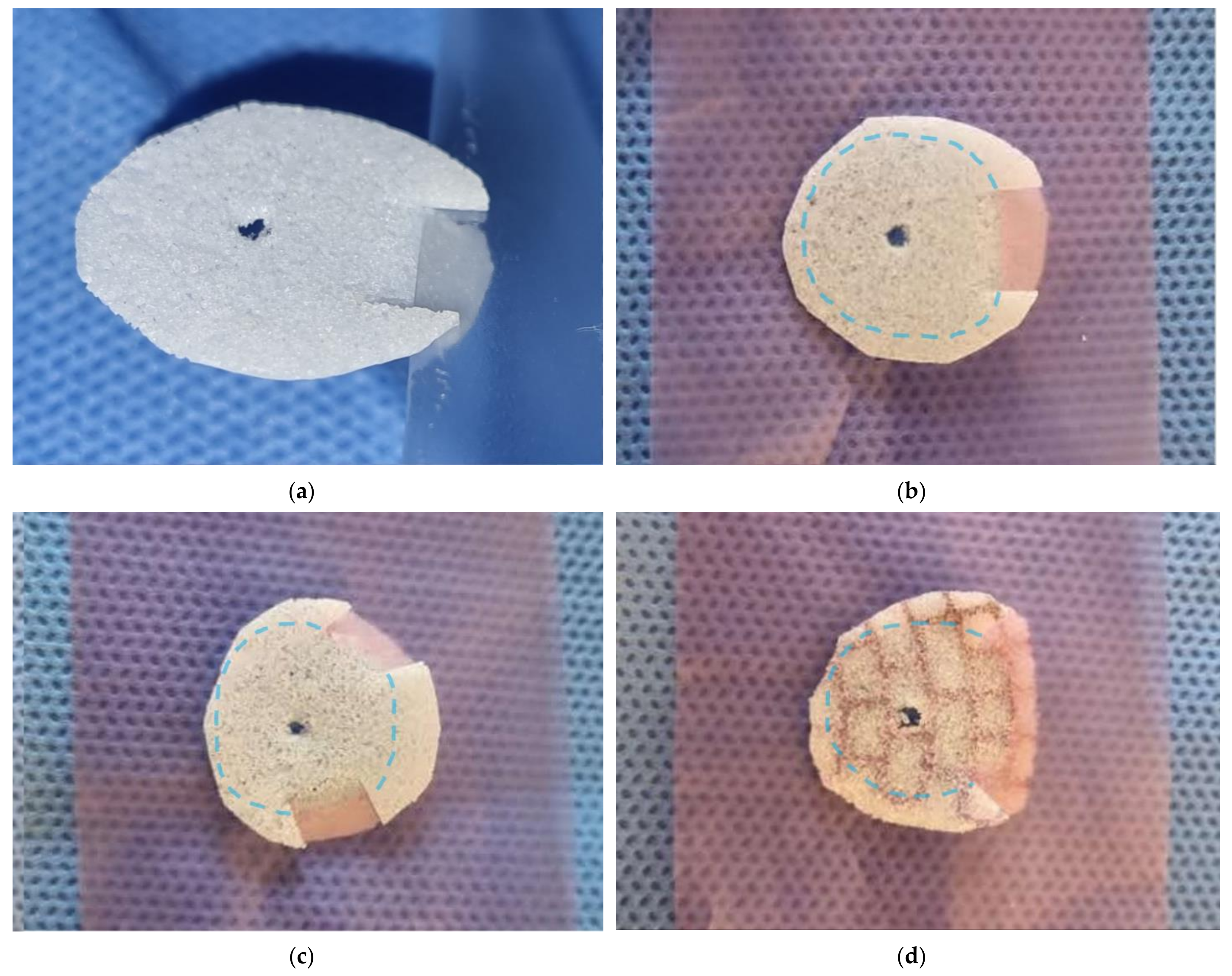
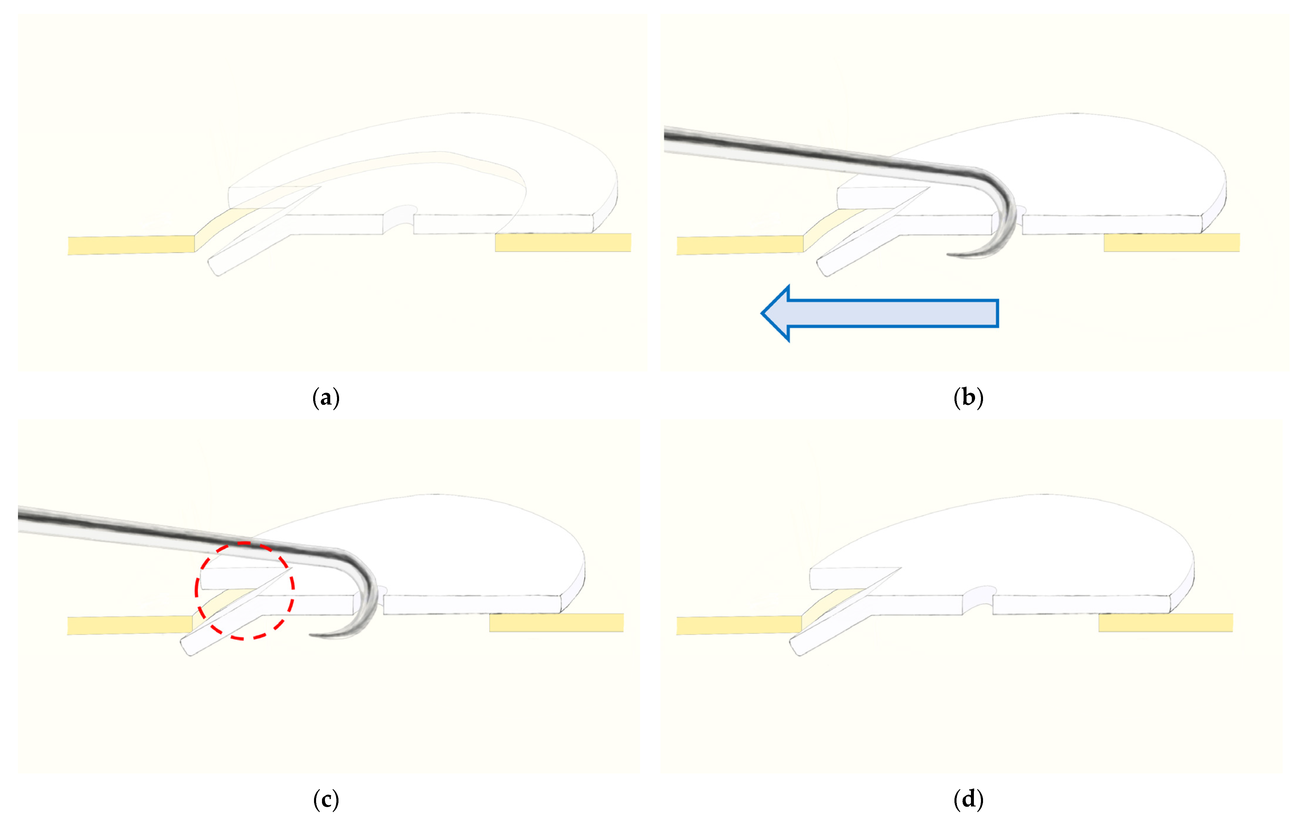
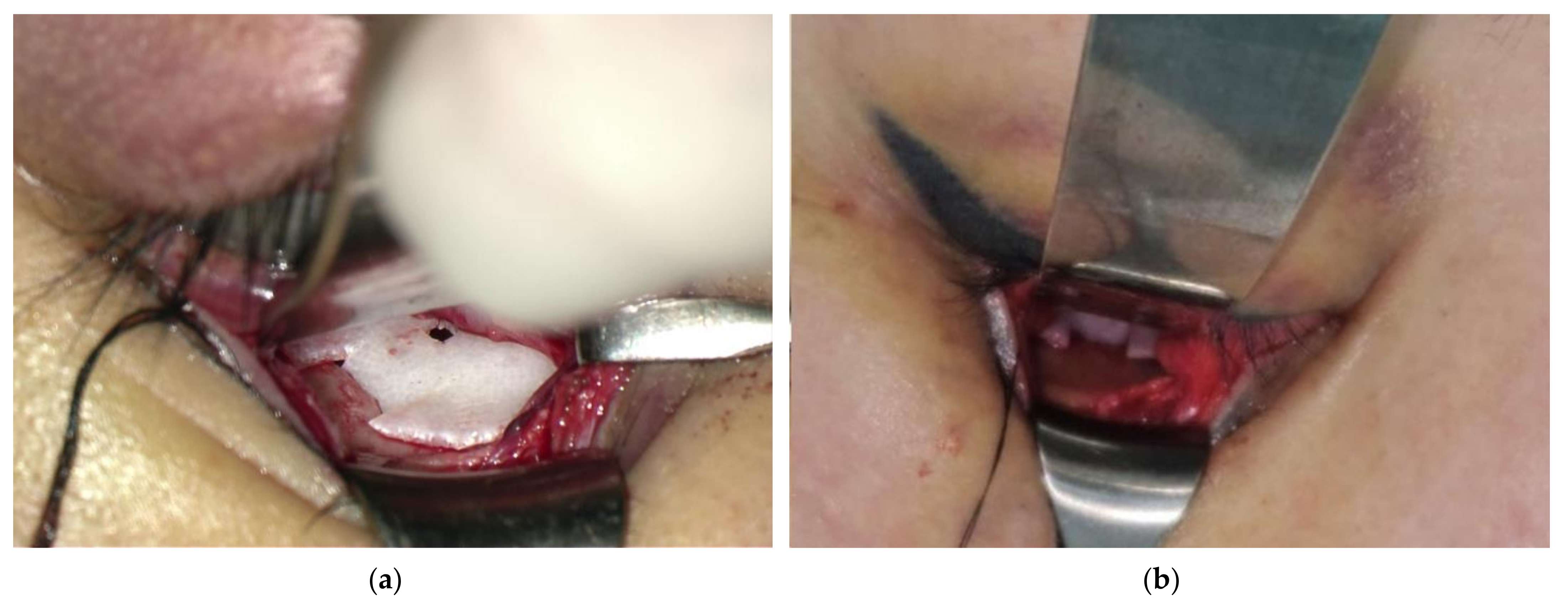
2.2. Surgical Procedure
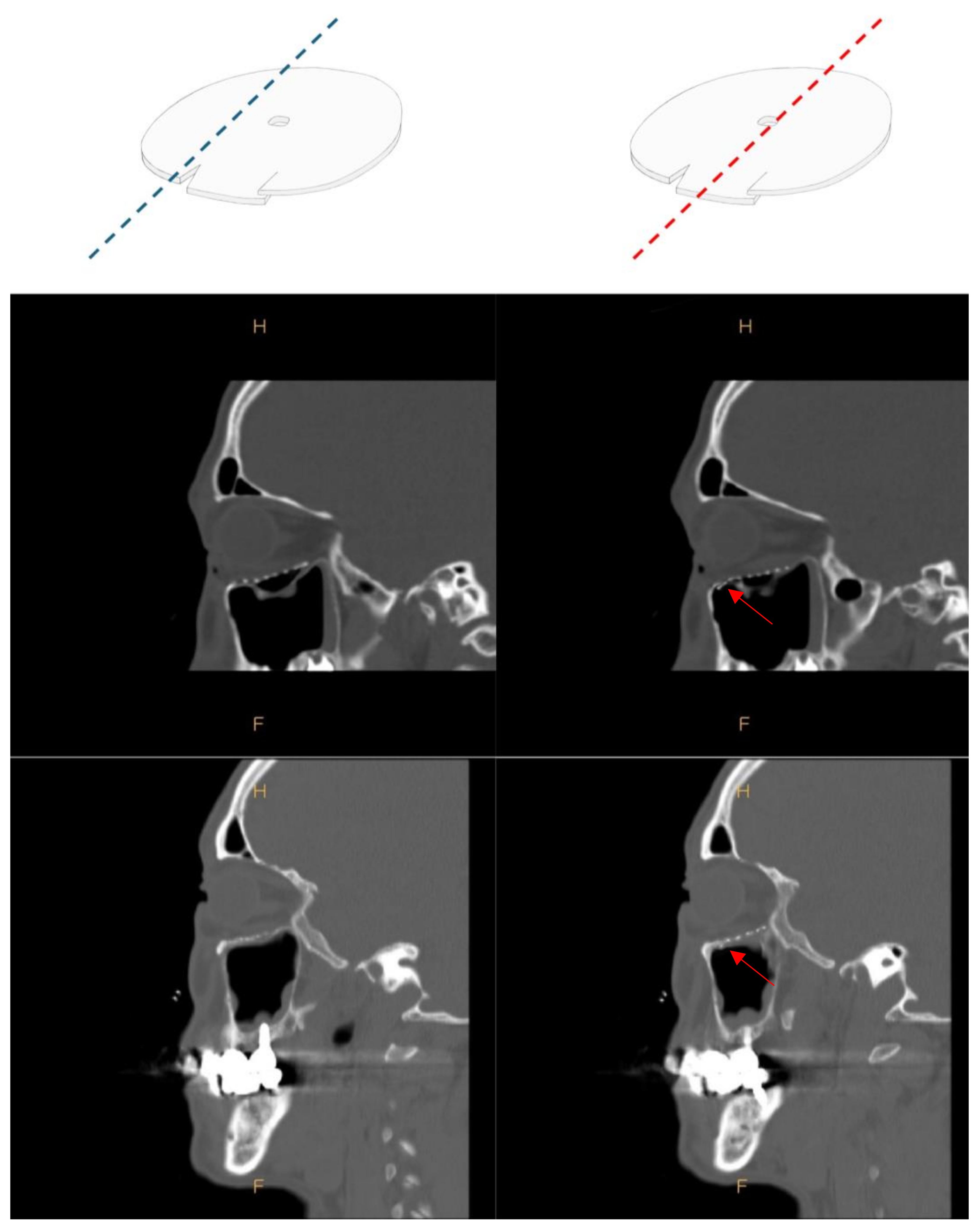
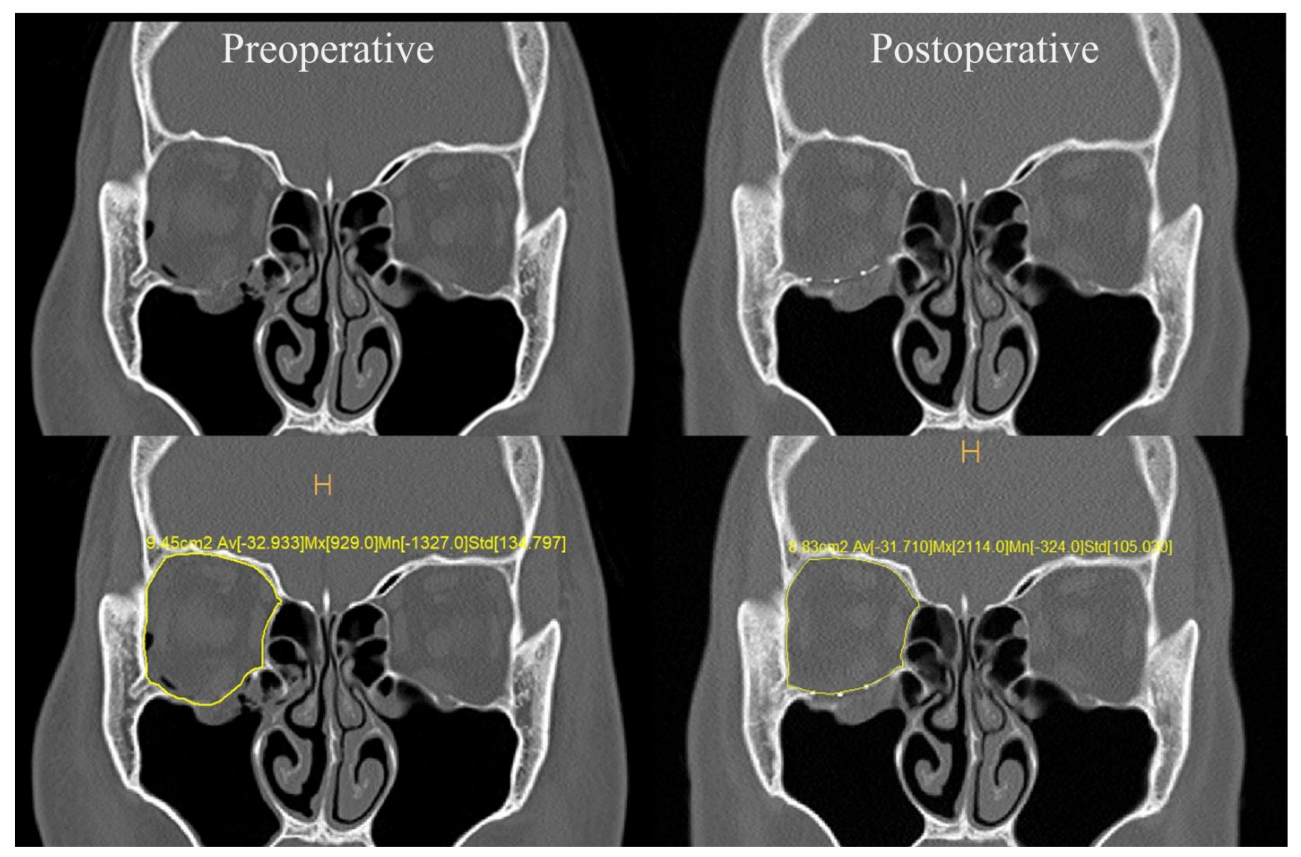
2.3. Orbital Volume Measurement and Exophthalmometry Measurements
3. Results
4. Discussion
5. Conclusions
Author Contributions
Funding
Institutional Review Board Statement
Informed Consent Statement
Data Availability Statement
Conflicts of Interest
References
- Park, A.H.; Diaz, J.A. A different approach to orbital blow out fractures: Microscope-assisted reconstruction of the orbital floor. Int. J. Pediatr. Otorhinolaryngol. 2008, 72, 707–710. [Google Scholar] [CrossRef]
- Matsuda, Y.; Sakaida, H.; Kobayashi, M.; Takeuchi, K. Successful application of endoscopic modified medial maxillectomy to orbital floor trapdoor fracture in a pediatric patient. Auris Nasus Larynx 2016, 43, 575–578. [Google Scholar] [CrossRef]
- Seen, S.; Young, S.; Lang, S.S.; Lim, T.C.; Amrith, S.; Sundar, G. Orbital Implants in Orbital Fracture Reconstruction: A Ten-Year Series. Craniomaxillofac. Trauma Reconstr. 2021, 14, 56–63. [Google Scholar] [CrossRef]
- Baviskar, P.S.; Natarajan, S. Use of custom fabricated surgical jig to improve surgical outcomes in open reduction internal fixation of unilateral orbital fractures: A prospective clinical study. Saudi J. Ophthalmol. 2021, 35, 244–250. [Google Scholar] [CrossRef] [PubMed]
- Zimmerer, R.M.; Ellis, E.; Aniceto, G.S.; Schramm, A.; Wagner, M.H.; Grant, M.P.; Cornelius, C.P.; Strong, E.B.; Rana, M.; Chye, L.T.; et al. A prospective multicenter study to compare the precision of posttraumatic internal orbital reconstruction with standard preformed and individualized orbital implants. J. Craniomaxillofac. Surg. 2016, 44, 1485–1497. [Google Scholar] [CrossRef]
- Sigron, G.R.; Barba, M.; Chammartin, F.; Msallem, B.; Berg, B.I.; Thieringer, F.M. Functional and Cosmetic Outcome after Reconstruction of Isolated, Unilateral Orbital Floor Fractures (Blow-Out Fractures) with and without the Support of 3D-Printed Orbital Anatomical Models. J. Clin. Med. 2021, 10, 3509. [Google Scholar] [CrossRef]
- Kittichokechai, P.; Sirichatchai, K.; Puncreobutr, C.; Lohwongwatana, B.; Saonanon, P. A Novel Patient-specific Titanium Mesh Implant Design for Reconstruction of Complex Orbital Fracture. Plast. Reconstr. Surg. Glob. Open 2022, 10, e4081. [Google Scholar] [CrossRef]
- Kanno, T.; Sukegawa, S.; Karino, M.; Furuki, Y. Navigation-Assisted Orbital Trauma Reconstruction Using a Bioactive Osteoconductive/Bioresorbable u-HA/PLLA System. J. Maxillofac. Oral Surg. 2019, 18, 329–338. [Google Scholar] [CrossRef] [PubMed]
- De Cuyper, B.; Abeloos, J.; Swennen, G.; Pottel, L. Intraoperative Navigation and Cone Beam Computed Tomography for Restoring Orbital Dimensions: A Single-Center Experience. Craniomaxillofac. Trauma Reconstr. 2020, 2, 84–92. [Google Scholar] [CrossRef] [PubMed]
- Brown, A.E.; Banks, P. Late extrusion of alloplastic orbital floor implants. Br. J. Oral Maxillofac. Surg. 1993, 31, 154–157. [Google Scholar] [CrossRef]
- Dancey, A.L.; Perry, M.J. Late presentation of alloplastic implant extrusion. Plast. Reconstr. Surg. 2004, 113, 1081–1082. [Google Scholar] [CrossRef] [PubMed]
- Weintraub, B.; Cucin, R.L.; Jacobs, M. Extrusion of an infected orbital-floor prosthesis after 15 years. Plast. Reconstr. Surg. 1981, 68, 586–587. [Google Scholar] [CrossRef]
- Cung, T.D.; Hu, S.; Govindaraj, S.; Elahi, E. Preservation of Infraorbital Nerve in Orbital Floor and Maxillary Defect Reconstruction With Patient-Specific Three-Dimensional Implant: A Case Report. Ophthalmic Plast. Reconstr. Surg. 2022, 38, e136–e141. [Google Scholar] [CrossRef]
- Abdelazeem, M.H.; Erdogan, Ö.; Osman, M.F.; Awad, T.A. Implications of an Anatomical Variation of the Infraorbital Nerve in Orbital Floor Reconstruction. J. Craniofac. Surg. 2022, 33, e572–e573. [Google Scholar] [CrossRef]
- Arnold, R.W. The Oculocardiac Reflex: A Review. Clin. Ophthalmol. 2021, 24, 2693–2725. [Google Scholar] [CrossRef]
- Monstrey, S.; Middelkoop, E.; Vranckx, J.J.; Bassetto, F.; Ziegler, U.E.; Meaume, S.; Téot, L. Updated scar management practical guidelines: Non-invasive and invasive measures. J. Plast. Reconstr. Aesthet. Surg. 2014, 67, 1017–1025. [Google Scholar] [CrossRef] [PubMed]
- Byrne, M.; Aly, A. The Surgical Suture. Aesthet. Surg. J. 2019, 39, S67–S72. [Google Scholar] [CrossRef] [PubMed]
- Grob, S.; Yonkers, M.; Tao, J. Orbital Fracture Repair. Semin. Plast. Surg. 2017, 31, 31–39. [Google Scholar] [CrossRef]
- Wi, J.M.; Sung, K.H.; Chi, M. ‘Orbital volume restoration rate after orbital fracture’; a CT-based orbital volume measurement for evaluation of orbital wall reconstructive effect. Eye 2017, 31, 713–719. [Google Scholar] [CrossRef]
- Seifert, L.B.; Mainka, T.; Herrera-Vizcaino, C.; Verboket, R.; Sader, R. Orbital floor fractures: Epidemiology and outcomes of 1594 reconstructions. Eur. J. Trauma Emerg. Surg. 2022, 48, 1427–1436. [Google Scholar] [CrossRef]
- Ho, V.H.; Rowland, J.P.; Linder, J.S.; Fleming, J.C. Sutureless transconjunctival repair of orbital blowout fractures. Ophthalmic Plast. Reconstr. Surg. 2004, 20, 458–460. [Google Scholar] [CrossRef]
- Kohn, R.; Romano, P.E.; Puklin, J.E. Lacrimal obstruction after migration of orbital floor implant. Am. J. Ophthalmol. 1976, 82, 934–936. [Google Scholar] [CrossRef] [PubMed]
- Rosen, C.E. Late migration of an orbital implant causing orbital hemorrhage with sudden proptosis and diplopia. Ophthalmic Plast. Reconstr. Surg. 1996, 12, 260–262. [Google Scholar] [CrossRef] [PubMed]
- Bonavolontà, G. Postoperative blindness following orbital surgery. Orbit 2005, 24, 195–200. [Google Scholar] [CrossRef] [PubMed]
- Kumaran, A.M.; Sundar, G.; Chye, L.T. Traumatic optic neuropathy: A review. Craniomaxillofac. Trauma Reconstr. 2015, 8, 31–41. [Google Scholar] [CrossRef] [PubMed]
- Kim, Y.H.; Kim, T.G.; Lee, J.H.; Nam, J.H.; Lim, J.H. Inlay implanting technique for the correction of medial orbital wall fracture. Plast. Reconstr. Surg. 2011, 127, 321–326. [Google Scholar] [CrossRef] [PubMed]
- Hwang, W.S.; Kim, J.W. Reconstruction of extended orbital floor fracture using an implantation method of gamma-shaped porous polyethylene. Arch. Craniofac. Surg. 2019, 20, 164–169. [Google Scholar] [CrossRef] [PubMed]
- Hwang, K.; Kita, Y. Alloplastic template fixation of blow-out fracture. J. Craniofac. Surg. 2002, 13, 510–512. [Google Scholar] [CrossRef]
- Ngo, H.X.; Bai, Y.; Sha, J.; Ishizuka, S.; Toda, E.; Osako, R.; Kato, A.; Morioka, R.; Ramanathan, M.; Tatsumi, H.; et al. A Narrative Review of u-HA/PLLA, a Bioactive Resorbable Reconstruction Material: Applications in Oral and Maxillofacial Surgery. Materials 2021, 15, 150. [Google Scholar] [CrossRef]
- Chattopadhyay, C.; Dev, V.; Pilania, D.; Harsh, A. Reconstruction of Orbital Floor Fractures with Titanium Micromesh: Our Experience. Maxillofac. Oral Surg. 2022, 21, 369–378. [Google Scholar] [CrossRef]
- Simon, G.J.; Bush, S.; Selva, D.; McNab, A.A. Orbital cellulitis: A rare complication after orbital blowout fracture. Ophthalmology 2005, 112, 2030–2034. [Google Scholar] [CrossRef] [PubMed]
- Yu, J.; Zhang, J.; Chen, S.; Han, Q.; Yan, H. Repair of unilateral combined orbital floor and medial wall fracture using two titanium mesh plates: A modified technique. Ann. Transl. Med. 2021, 9, 463. [Google Scholar] [CrossRef] [PubMed]
- Kasrai, L.; Hearn, T.; Forrest, E.G. A biomechanical analysis of the orbitozygomatic complex in human cadavers: Examination of load sharing and failure patterns following fixation with titanium and bioresorbable plating systems. J. Craniofac. Surg. 1999, 10, 237–243. [Google Scholar] [CrossRef]
- Kim, J.H.; Lee, I.G.; Lee, J.S.; Oh, D.T.; Jun, Y.J.; Rhie, J.W.; Shim, J.H.; Moon, S.H. Restoration of the inferomedial orbital strut using a standardized three-dimensional printing implant. J. Anat. 2020, 236, 923–930. [Google Scholar] [CrossRef]
- Wilkat, M.; Hufendiek, K.; Karahisarlioglu, M.; Borrelli, M.; Sproll, C.; Rana, M. Prospective Evaluation of Two Wall Orbital Fractures Involving the Medial Orbital Wall: PSI Reconstruction versus PDS Repair-Worth the Effort? J. Pers. Med. 2022, 12, 1389. [Google Scholar] [CrossRef] [PubMed]
- Andrades, P.; Cuevas, P.; Hernández, R.; Danilla, S.; Villalobos, R. Characterization of the orbital volume in normal population. J. Craniomaxillofac. Surg. 2018, 46, 594–599. [Google Scholar] [CrossRef]
- Wu, D.; Liu, X.; Wu, D.; Di, X.; Guan, H.; Shan, Z.; Teng, W. Normal values of Hertel exophthalmometry in a Chinese Han population from Shenyang, Northeast China. Sci. Rep. 2015, 5, 8526. [Google Scholar] [CrossRef]
- René, C. Update on orbital anatomy. Eye 2006, 20, 1119–1129. [Google Scholar] [CrossRef]
- Choi, K.E.; Lee, J.S.; Lee, H.; Chang, M.W.; Park, M.S.; Baek, S.H. The Paradoxical Predominance of Medial Wall Injuries in Blowout Fracture. J. Craniofac. Surg. 2015, 26, e752–e7555. [Google Scholar] [CrossRef]
- Farber, S.J.; Yu, J.L.; Nguyen, D.C.; Woo, A.S. Fenestration of Solid Orbital Implants: Reducing Retrobulbar Hematoma Rate. J. Craniofac. Surg. 2017, 28, 248–249. [Google Scholar] [CrossRef]
- Sivam, A.; Enninghorst, N. The Dilemma of Reconstructive Material Choice for Orbital Floor Fracture: A Narrative Review. Medicines 2022, 9, 6. [Google Scholar] [CrossRef]
- North, V.S.; Reshef, E.R.; Lee, N.G.; Lefebvre, D.R.; Freitag, S.K.; Yoon, M.K. Lower eyelid malposition following repair of complex orbitofacial trauma. Orbit 2022, 41, 193–198. [Google Scholar] [CrossRef]
- Yang, E.; Chan, S.C.; Al-Omari, Y.; Ward, L.; Yap, T.E.; Jhass, A.; Pancholi, R.; Aziz, A.; Bentley, C.R.; Perry, M.; et al. A Functional Radiological and Soft Tissue Classification to Predict Outcomes in Orbital Fracture Surgery in a Multidisciplinary “Real-World” Setting. Ront. Surg. 2021, 8, 693607. [Google Scholar] [CrossRef]
- Ross, M.; El-Haddad, C.; Deschênes, J. Ocular injury in orbital fractures at a level I trauma center. Can. J. Ophthalmol. 2017, 52, 499–502. [Google Scholar] [CrossRef]
- al-Qurainy, I.A.; Stassen, L.F.; Dutton, G.N.; Moos, K.F.; el-Attar, A. The characteristics of midfacial fractures and the association with ocular injury: A prospective study. Br. J. Oral. Maxillofac. Surg. 1991, 29, 291–301. [Google Scholar] [CrossRef] [PubMed]
- Ho, T.Q.; Jupiter, D.; Tsai, J.H.; Czerwinski, M. The Incidence of Ocular Injuries in Isolated Orbital Fractures. Ann. Plast. Surg. 2017, 78, 59–61. [Google Scholar] [CrossRef] [PubMed]
- Luce, E.A.; Tubb, T.D.; Moore, A.M. Review of 1,000 major facial fractures and associated injuries. Plast. Reconstr. Surg. 1979, 63, 26–30. [Google Scholar] [CrossRef] [PubMed]


| n = 138 | |||
|---|---|---|---|
| Sex | Male | 115 | (83.3%) |
| Female | 23 | (16.7%) | |
| Cause | Human trouble | 46 | (33.3%) |
| Direct trauma | 33 | (23.9%) | |
| Slip down | 39 | (28.3%) | |
| Traffic accident | 16 | (11.6%) | |
| Fall | 4 | (2.9%) | |
| Location of fracture | Inferior | 55 | (39.8%) |
| Medial | 55 | (39.8%) | |
| Inferior + Medial | 28 | (20.4%) | |
| Mean ± SD | p | ||
|---|---|---|---|
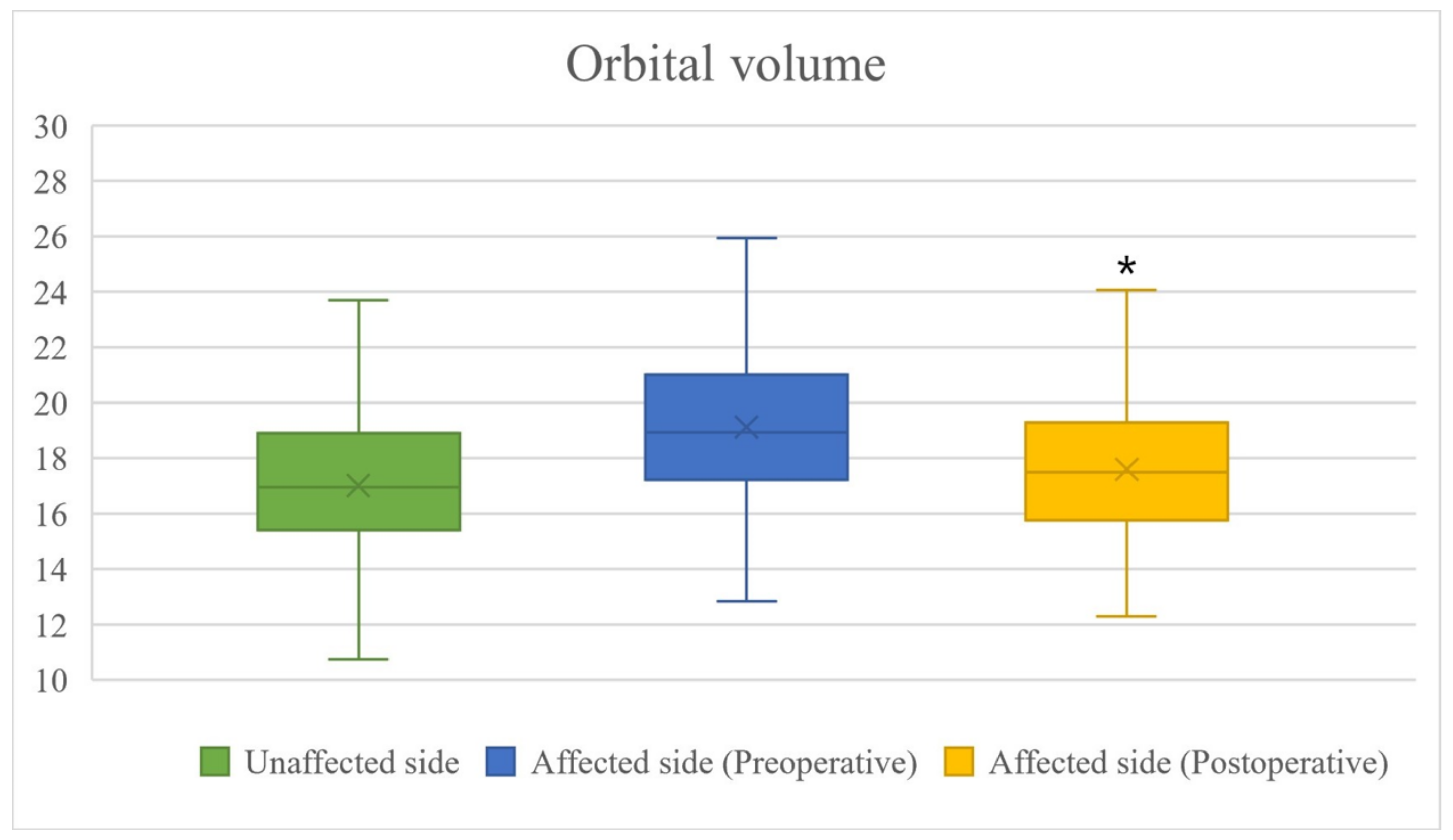
| OV (mm3) | Preoperative difference | 2107.35 ± 1216.62 | 0.1129 |
| Postoperative difference | 583.27 ± 891.21 | <0.0001 | |
| OVR (%) | Preoperative OVR | 87.15 ± 7.75 | 0.4421 |
| Postoperative OVR | 94.21 ± 6.06 | <0.0001 |
| Preoperative | Postoperative | |
|---|---|---|
| Diplopia | 42 (30.4%) | 22 (15.9%) |
| Hypoesthesia | 19 (13.8%) | 15 (10.9%) |
| Enophthalmos | 12 (8.6%) | 6 (4.3%) |
| Ectropion | 0 | 1 (0.7%) |
| Implant migration | 0 | 1 (0.7%) |
| Retrobulbar hematoma | 1 (0.7%) | 0 (0%) |
Disclaimer/Publisher’s Note: The statements, opinions and data contained in all publications are solely those of the individual author(s) and contributor(s) and not of MDPI and/or the editor(s). MDPI and/or the editor(s) disclaim responsibility for any injury to people or property resulting from any ideas, methods, instructions or products referred to in the content. |
© 2024 by the authors. Licensee MDPI, Basel, Switzerland. This article is an open access article distributed under the terms and conditions of the Creative Commons Attribution (CC BY) license (https://creativecommons.org/licenses/by/4.0/).
Share and Cite
Byeon, J.-Y.; Hwang, Y.-S.; Choi, H.-J.; Lee, D.-W.; Kim, J.-H. Tongue-in-Groove: A Novel Implant Design for a Blow-Out Fracture. J. Clin. Med. 2024, 13, 1766. https://doi.org/10.3390/jcm13061766
Byeon J-Y, Hwang Y-S, Choi H-J, Lee D-W, Kim J-H. Tongue-in-Groove: A Novel Implant Design for a Blow-Out Fracture. Journal of Clinical Medicine. 2024; 13(6):1766. https://doi.org/10.3390/jcm13061766
Chicago/Turabian StyleByeon, Je-Yeon, Yong-Seon Hwang, Hwan-Jun Choi, Da-Woon Lee, and Jun-Hyuk Kim. 2024. "Tongue-in-Groove: A Novel Implant Design for a Blow-Out Fracture" Journal of Clinical Medicine 13, no. 6: 1766. https://doi.org/10.3390/jcm13061766
APA StyleByeon, J.-Y., Hwang, Y.-S., Choi, H.-J., Lee, D.-W., & Kim, J.-H. (2024). Tongue-in-Groove: A Novel Implant Design for a Blow-Out Fracture. Journal of Clinical Medicine, 13(6), 1766. https://doi.org/10.3390/jcm13061766