
The Position of the Virtual Hinge Axis in Relation to the Maxilla in Digital Orthognathic Surgery Planning—A k-Means Cluster Analysis

 ,
,  , ,
, ,
Abstract
1. Introduction
2. Materials and Methods
Statistical Analysis
3. Results
3.1. Cluster Identification
3.2. Cluster-Specific Skeletal Phenotypes
4. Discussion
5. Conclusions
Author Contributions
Funding
Institutional Review Board Statement
Informed Consent Statement
Data Availability Statement
Conflicts of Interest
References
- Bonwill, W.G.A. Geometrical and Mechanical Laws of Articulation. Trans. Odont. Soc. Penna 1885, 119–133. [Google Scholar]
- Ohm, E.; Silness, J. The Size of the Balkwill Angle and the Height of the Bonwill Triangle. J. Oral Rehabil. 1982, 9, 301–306. [Google Scholar] [CrossRef] [PubMed]
- Carossa, M.; Cavagnetto, D.; Ceruti, P.; Mussano, F.; Carossa, S. Individual Mandibular Movement Registration and Reproduction Using an Optoeletronic Jaw Movement Analyzer and a Dedicated Robot: A Dental Technique. BMC Oral Health 2020, 20, 271. [Google Scholar] [CrossRef] [PubMed]
- Ganesh, M.K.A.; Mohanraj, K.G. Morphometric Analysis of Bonwill’s Triangle and Its Dental Applications in Dry Human Mandible Bones. J. Adv. Pharm. Technol. Res. 2022, 13 (Suppl. 1), 194–197. [Google Scholar]
- Lin, E.; Julien, K.; Kesterke, M.; Buschang, P.H. Differences in Finished Case Quality between Invisalign and Traditional Fixed Appliances: A randomized controlled trial. Angle Orthod. 2022, 92, 173–179. [Google Scholar] [CrossRef]
- Ahlers, M.O.; Edelhoff, D.; Jakstat, H.A. Reproduction Accuracy of Articulator Mounting with an Arbitrary Face-Bow vs. Average Values—A Controlled, Randomized, Blinded Patient Simulator Study. Clin. Oral Investig. 2019, 23, 1007–1014. [Google Scholar] [CrossRef] [PubMed]
- Lepidi, L.; Galli, M.; Mastrangelo, F.; Venezia, P.; Joda, T.; Wang, H.L.; Li, J. Virtual Articulators and Virtual Mounting Procedures: Where Do We Stand? J. Prosthodont. 2021, 30, 24–35. [Google Scholar] [CrossRef] [PubMed]
- Solaberrieta, E.; Garmendia, A.; Minguez, R.; Brizuela, A.; Pradies, G. Virtual Facebow Technique. J. Prosthet. Dent. 2015, 114, 751–755. [Google Scholar] [CrossRef]
- Lam, W.Y.H.; Hsung, R.T.C.; Choi, W.W.S.; Luk, H.W.K.; Cheng, L.Y.Y.; Pow, E.H.N. A Clinical Technique for Virtual Articulator Mounting with Natural Head Position by Using Calibrated Stereophotogrammetry. J. Prosthet. Dent. 2018, 119, 902–908. [Google Scholar] [CrossRef]
- Lepidi, L.; Chen, Z.; Ravida, A.; Lan, T.; Wang, H.L.; Li, J. A Full-Digital Technique to Mount a Maxillary Arch Scan on a Virtual Articulator: Virtual Facebow Technique. J. Prosthodont. 2019, 28, 335–338. [Google Scholar] [CrossRef]
- Stamm, T.; Andriyuk, E.; Kleinheinz, J.; Jung, S.; Dirksen, D.; Middelberg, C. In Vivo Accuracy of a New Digital Planning System in Terms of Jaw Relation, Extent of Surgical Movements and the Hierarchy of Stability in Orthognathic Surgery. J. Pers. Med. 2022, 12, 843. [Google Scholar] [CrossRef] [PubMed]
- Li, D.T.S.; Leung, Y.Y. Patient-Specific Implants in Orthognathic Surgery. Oral Maxillofac. Surg. Clin. 2023, 35, 61–69. [Google Scholar] [CrossRef] [PubMed]
- Stamm, T.; Böttcher, D.; Kleinheinz, J. The University Münster Model Surgery System for Orthognathic Surgery—The Digital Update. Head Face Med. 2021, 17, 31. [Google Scholar] [CrossRef]
- Ehmer, U.; Austermann, K.H. Die Rolle des Kieferorthopäden für die Motivation zu chirurgisch-kieferorthopädischen Therapiemaßnahmen. Fortschr. Kieferorthop. 1987, 48, 246–253. [Google Scholar] [CrossRef]
- Ehmer, U.; Joos, U.; Flieger, S.; Wiechmann, D. The University Münster Model Surgery System for Orthognathic Surgery. Part I—The Idea Behind. Head Face Med. 2012, 8, 14. [Google Scholar] [CrossRef] [PubMed]
- Ehmer, U.; Joos, U.; Ziebura, T.; Flieger, S.; Wiechmann, D. The University Münster Model Surgery System for Orthognathic Surgery. Part II—KD-MMS. Head Face Med. 2013, 9, 2. [Google Scholar] [CrossRef] [PubMed]
- Schneider, C.A.; Rasband, W.S.; Eliceiri, K.W. NIH Image to ImageJ: 25 Years of Image Analysis. Nat. Methods 2012, 9, 671–675. [Google Scholar] [CrossRef]
- Ricketts, R.M. Cephalometric Analysis and Synthesis. Angle Orthod. 1961, 31, 141–156. [Google Scholar]
- Rakosi, T. Atlas Und Anleitung Zur Praktischen Fernröntgenanalyse, 2nd ed.; Hanser: München, Germany; Wien, Austria, 1988. [Google Scholar]
- Downs, W.B. The Role of Cephalometrics in Orthodontic Case Analysis and Diagnosis. Am. J. Orthod. 1952, 38, 162–182. [Google Scholar] [CrossRef]
- Steiner, C.C. Cephalometrics for You and Me. Am. J. Orthod. 1953, 39, 729–755. [Google Scholar] [CrossRef]
- Barretto, M.D.; Melhem-Elias, F.; Deboni, M.C. Methods of Mandibular Condyle Position and Rotation Center Used for Orthognathic Surgery Planning: A Systematic Review. J. Stomatol. Oral Maxillofac. Surg. 2022, 123, 345–352. [Google Scholar] [CrossRef]
- Nattestad, A.; Vedtofte, P. Mandibular Autorotation in Orthognathic Surgery: A New Method of Locating the Centre of Mandibular Rotation and Determining Its Consequence in Orthognathic Surgery. J. Craniomaxillofac. Surg. 1992, 20, 163–170. [Google Scholar] [CrossRef] [PubMed]
- Quast, A.; Santander, P.; Trautmann, J.; Moser, N.; Schliephake, H.; Meyer-Marcotty, P. A New Approach in Three Dimensions to Define Pre- and Intraoperative Condyle-Fossa Relationships in Orthognathic Surgery-Is There an Effect of General Anaesthesia on Condylar Position? Int. J. Oral Maxillofac. Surg. 2020, 49, 1303–1310. [Google Scholar] [CrossRef]
- Costa, F.; Robiony, M.; Toro, C.; Sembronio, S.; Polini, F.; Politi, M. Condylar Positioning Devices for Orthognathic Surgery: A Literature Review. Oral Surg. Oral Med. Oral Pathol. Oral Radiol. Endod. 2008, 106, 179–190. [Google Scholar] [CrossRef] [PubMed]
- Proffit, W.R.; Turvey, T.A.; Phillips, C. The Hierarchy of Stability and Predictability in Orthognathic Surgery with Rigid Fixation: An Update and Extension. Head Face Med. 2007, 3, 21. [Google Scholar] [CrossRef]
- Hsu, S.S.P.; Gateno, J.; Bell, R.B.; Hirsch, D.L.; Markiewicz, M.R.; Teichgraeber, J.F.; Zhou, X.; Xia, J.J. Accuracy of a Computer-Aided Surgical Simulation Protocol for Orthognathic Surgery: A Prospective Multicenter Study. J. Oral Maxillofac. Surg. 2013, 71, 128–142. [Google Scholar] [CrossRef]
- Maggetti, I.; Bindl, A.; Mehl, A. A three-dimensional morphometric study on the position of temporomandibular joints. Int. J. Comput. Dent. 2015, 18, 319–331. [Google Scholar]
- Schwestka-Polly, R.; Kubein-Meesenburg, D.; Luhr, H.G. Ergebnisse der Anwendung des Göttinger Konzepts zur räumlichen Einstellung des Oberkiefers nach Umstellungsosteotomien. Mund Kiefer Gesichtschir. 1999, 3, 123–130. [Google Scholar] [CrossRef]
- Sharifi, A.; Jones, R.; Ayoub, A.; Moos, K.; Walker, F.; Khambay, B.; McHugh, S. How Accurate Is Model Planning for Orthognathic Surgery? Int. J. Oral Maxillofac. Surg. 2008, 37, 1089–1093. [Google Scholar] [CrossRef]
- Diaconu, A.; Holte, M.B.; Berg-Beckhoff, G.; Pinholt, E.M. Three-Dimensional Accuracy and Stability of Personalized Implants in Orthognathic Surgery: A Systematic Review and a Meta-Analysis. J. Pers. Med. 2023, 13, 125. [Google Scholar] [CrossRef]


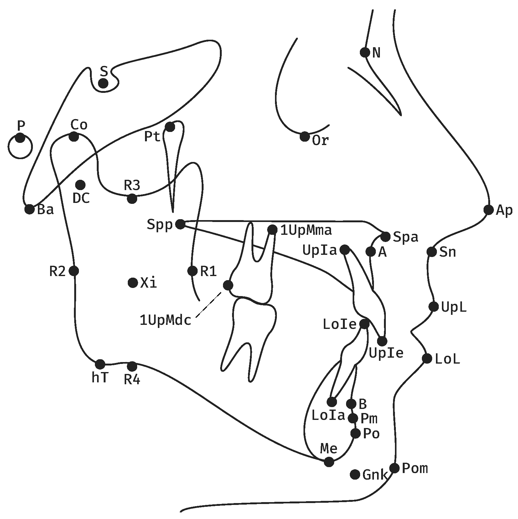
| Measurement | Definition | |
|---|---|---|
| 1 | Facial axis | Posterior angle btw. Ba-N and Pt-GnK. |
| 2 | Facial depth | Posterior angle btw. P-Or and N-Po. |
| 3 | SNB | Posterior lower angle btw. S-N and N-B. |
| 4 | Mandibular plane | Anterior angle btw. P-Or and hT-Me. |
| 5 | Inner gonion angle | Anterior angle btw. DC-Xi and Xi-Pm. |
| 6 | Relative mandibular length | Length of Co-Po. |
| 7 | Maxillary position | Posterior lower angle btw. Ba-N and N-A. |
| 8 | SNA | Posterior lower angle btw. S-N and N-A. |
| 9 | Palatal plane | Anterior angle btw. P-Or and Spa-Spp. |
| 10 | Rel. max. length | Length of Co-A. |
| 11 | Lower facial height | Anterior angle btw. Spa-Xi and Xi-Pm. |
| 12 | Convexity of point A | Distance btw. A and N-Po. |
| 13 | Rel. max. to mand. length | Ratio btw. Co-A and Co-Po. |
| 14 | Lower Incisor position | Distance btw. LoIe and A-Po. |
| 15 | Lower Incisor inclination | Caudal angle btw. LoIe-LoIa and A-Po. |
| 16 | Upper Incisor position | Distance btw. UpIe and A-Po. |
| 17 | Upper Incisor inclination | Caudal angle btw. UpIe-UpIa and A-Po. |
| 18 | Inter-Incisor angle | Anterior angle btw. UpIe-UpIa and LoIe-LoIa. |
| 19 | Vertical molar distance | Distance btw. 1UpMma and Spa-Spp. |
| 20 | Sagittal molar distance | Distance btw. 1UpMdc and a vertical to P-Or from Pt. |
| 21 | Lower Lip to E-Line | Distance btw. LoL and Ap-Pom. |
| 22 | Upper Lip Drape | Posterior angle btw. UpL-Sn and P-Or. |
| Female | Male | p | |||||
|---|---|---|---|---|---|---|---|
| n | M | SD | n | M | SD | ||
| age | 323 | 26.1 | 8.7 | 191 | 27.9 | 8.3 | <0.001 |
| 323 | 7.6 | 5.3 | 191 | 6.5 | 5.0 | ||
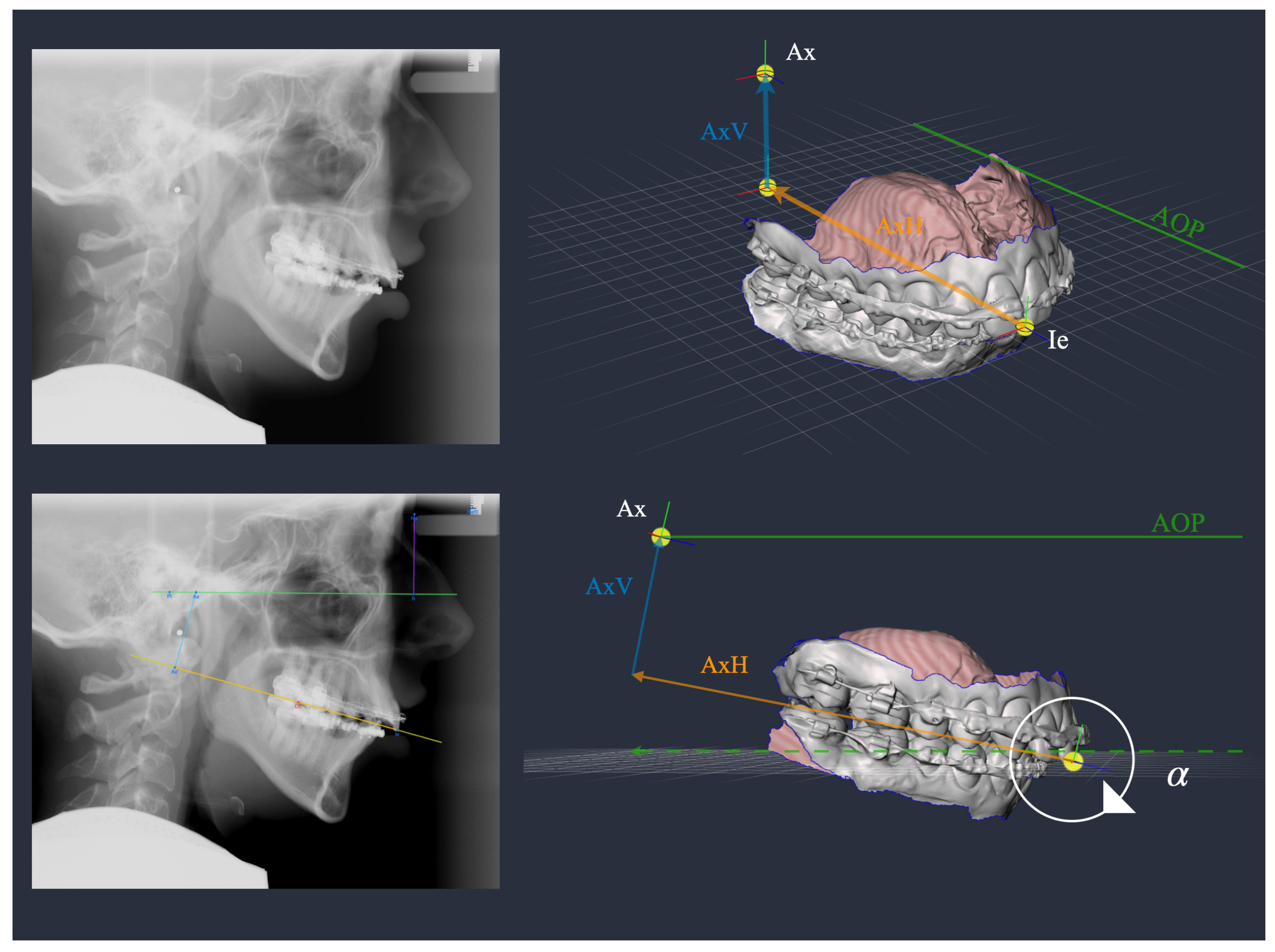
| AxV | 323 | 30.2 | 5.7 | 191 | 35.8 | 5.7 | <0.001 |
| AxH | 323 | 88.0 | 6.7 | 191 | 93.1 | 8.1 | <0.001 |
| Cluster 1 | Cluster 2 | Cluster 3 | p | ||||||||
|---|---|---|---|---|---|---|---|---|---|---|---|
| n | M | SD | n | M | SD | n | M | SD | |||
| age | 128 | 28.1 | 9.1 | 204 | 26.2 | 7.8 | 182 | 26.5 | 9.0 | n. s. | |
| female | 36 | 26.3 | 9.2 | 171 | 26.0 | 7.9 | 116 | 26.3 | 9.7 | n. s. | |
| male | 92 | 28.8 | 9.0 | 33 | 27.6 | 7.0 | 66 | 26.9 | 7.9 | n. s. | |
| 128 | 7.8 | 3.4 | 204 | 11.1 | 3.3 | 182 | 2.4 | 4.0 | <0.001 | ||
| AxV | 128 | 36.2 | 4.6 | 204 | 26.5 | 3.8 | 182 | 35.9 | 4.5 | <0.001 1 | |
| AxH | 128 | 98.9 | 5.5 | 204 | 88.1 | 5.4 | 182 | 85.6 | 5.6 | <0.001 | |
| Cluster 1 | Cluster 2 | Cluster 3 | p | ||||
|---|---|---|---|---|---|---|---|
| n = 128 | n = 204 | n = 182 | |||||
| M | SD | M | SD | M | SD | ||
| Facial axis | 89.1 | 5.7 | 85.7 | 5.9 | 91.8 | 6.5 | <0.001 |
| Facial depth | 89.5 | 4.8 | 85.7 | 5.0 | 92.1 | 5.3 | <0.001 |
| SNB | 80.2 | 5.6 | 76.0 | 5.2 | 82.4 | 6.4 | a |
| Rel. mand. length | 118.7 | 10.0 | 106.3 | 9.0 | 114.0 | 9.2 | <0.001 |
| SNA | 82.4 | 4.3 | 79.9 | 4.3 | 81.1 | 4.9 | a |
| Convexity of point A | 1.3 | 4.8 | 2.8 | 5.0 | −2.8 | 4.6 | b |
| Rel. max. to mand. length | 1.4 | 0.1 | 1.3 | 0.1 | 1.4 | 0.1 | a |
| Sagittal molar distance | 20.4 | 4.8 | 16.9 | 4.2 | 19.1 | 4.5 | a |
| Lower Lip to E-Line | −2.2 | 3.6 | −1.3 | 3.0 | −3.3 | 3.3 | b |
| Cluster 1 | Cluster 2 | Cluster 3 | p | ||||
|---|---|---|---|---|---|---|---|
| n = 128 | n = 204 | n = 182 | |||||
| M | SD | M | SD | M | SD | ||
| Ie-Ax | 105.4 | 5.7 | 92.1 | 5.3 | 92.9 | 5.9 | 1 |
| Balkwill | 20.1 | 2.4 | 16.8 | 2.4 | 22.8 | 2.5 | |
| Cluster | Skeletal Phenotype | AxV | AxH | |
|---|---|---|---|---|
| 1 | balanced face | 8 | 36 | 99 |
| 2 | vertical face, class II | 11 | 27 | 88 |
| 3 | horizontal face, class III | 2 | 36 | 86 |
Disclaimer/Publisher’s Note: The statements, opinions and data contained in all publications are solely those of the individual author(s) and contributor(s) and not of MDPI and/or the editor(s). MDPI and/or the editor(s) disclaim responsibility for any injury to people or property resulting from any ideas, methods, instructions or products referred to in the content. |
© 2023 by the authors. Licensee MDPI, Basel, Switzerland. This article is an open access article distributed under the terms and conditions of the Creative Commons Attribution (CC BY) license (https://creativecommons.org/licenses/by/4.0/).
Share and Cite
Stamm, T.; Kanemeier, M.; Dirksen, D.; Middelberg, C.; Hohoff, A.; Kleinheinz, J.; Schmid, J.Q. The Position of the Virtual Hinge Axis in Relation to the Maxilla in Digital Orthognathic Surgery Planning—A k-Means Cluster Analysis. J. Clin. Med. 2023, 12, 3582. https://doi.org/10.3390/jcm12103582
Stamm T, Kanemeier M, Dirksen D, Middelberg C, Hohoff A, Kleinheinz J, Schmid JQ. The Position of the Virtual Hinge Axis in Relation to the Maxilla in Digital Orthognathic Surgery Planning—A k-Means Cluster Analysis. Journal of Clinical Medicine. 2023; 12(10):3582. https://doi.org/10.3390/jcm12103582
Chicago/Turabian StyleStamm, Thomas, Moritz Kanemeier, Dieter Dirksen, Claudius Middelberg, Ariane Hohoff, Johannes Kleinheinz, and Jonas Q. Schmid. 2023. "The Position of the Virtual Hinge Axis in Relation to the Maxilla in Digital Orthognathic Surgery Planning—A k-Means Cluster Analysis" Journal of Clinical Medicine 12, no. 10: 3582. https://doi.org/10.3390/jcm12103582
APA StyleStamm, T., Kanemeier, M., Dirksen, D., Middelberg, C., Hohoff, A., Kleinheinz, J., & Schmid, J. Q. (2023). The Position of the Virtual Hinge Axis in Relation to the Maxilla in Digital Orthognathic Surgery Planning—A k-Means Cluster Analysis. Journal of Clinical Medicine, 12(10), 3582. https://doi.org/10.3390/jcm12103582