Article

A Novel Method to Combine Maxilla-Based Coordinate System and Mandibular Voxel-Based Superimposition with Cone-Bean Computed Tomography

1
State Key Laboratory of Oral Diseases & National Clinical Research Center for Oral Diseases, Department of Orthodontics, West China Hospital of Stomatology, Sichuan University, Chengdu 610041, China
2
State Key Laboratory of Oral Diseases & National Clinical Research Center for Oral Diseases, West China Hospital of Stomatology, Sichuan University, Chengdu 610041, China
3
State Key Laboratory of Oral Diseases & National Clinical Research Center for Oral Diseases, Department of Prosthodontics, West China Hospital of Stomatology, Sichuan University, Chengdu 610041, China
*
Authors to whom correspondence should be addressed.
J. Clin. Med. 2022, 11(17), 5229; https://doi.org/10.3390/jcm11175229
Submission received: 5 August 2022 / Revised: 28 August 2022 / Accepted: 1 September 2022 / Published: 4 September 2022
(This article belongs to the Topic Digital Dentistry)

Abstract

:
Background: The objective of this study was to propose a method that combines a maxilla-based coordinate system and mandibular voxel-based superimposition for an accurate evaluation of mandibular structural and positional changes and a direct comparison between maxillary and mandibular structural changes with the same 3D vectors. Methods: Mandibular voxel-based superimposition was firstly performed to reorient the mandibles and eliminate the mandibular positional changes. Then, a maxilla-based coordinate system was constructed with four maxillary skeletal landmarks (ANS, PNS, OrL and OrR). After settling the reoriented mandibles into this coordinate system, the mandibular structural changes were accurately evaluated. To assess the accuracy and reproducibility of this method, CBCT images of a skull specimen before and after orthodontic treatment (which was simulated by rearranging the skull and the mandible) were collected. Five mandibular skeletal landmarks, three mandibular dental landmarks and two mandibular measurement planes of this skull were used to evaluate the linear and angular changes in the mandibular structures. Results: There were significant differences in the linear and angular measurements of the mandibular structures of the skull (p ˂ 0.05), which indicated mandibular positional changes after orthodontic treatment. After mandibular voxel-based superimposition, there were no significant differences in the linear and angular measurements of mandibular structures, which indicated that the mandibular positional changes were eliminated. The intraclass correlation coefficient (ICC) value of the inter- and intra-observer agreement of all measurements was 0.99. Conclusions: This method has proven advantages in terms of accuracy, reproducibility and validity; with this method, mandibular structural and positional changes can be accurately evaluated and maxillary and mandibular structural changes can be directly compared with same 3D vectors.

1. Introduction

Cone-beam computer tomography (CBCT) is an increasingly widely used radiological technology in orthodontics because of its accurate three-dimensional (3D) performance, low distortion rate and relatively low radiation [1,2]. Three-dimensional reconstruction and superimposition make it easy to accurately evaluate treatment effects and analyze the skeletal and dental changes before and after treatment [3]. For measuring and comparing the three-dimensional positions of skeletal and dental structures, the common method is to set coordinate systems in the two 3D skull models reconstructed, respectively, with pre- and post- treatment CBCT images. In this process, most of the coordinate systems use maxillary landmarks as reference points, because these landmarks are relatively stable throughout treatment [4,5,6]. Our previous study has also proposed a maxilla-based personalized coordinate system, which is more user-friendly and can accurately evaluate the position changes in maxillary teeth and alveolar bones before and after orthodontic treatment [7]. However, none of the coordinate systems using maxillary landmarks is applicable for an accurate evaluation of the mandibular structural changes or the maxilla–mandible relationship in cases of functional orthopedic treatment or orthognathic surgery. The reason is that the mandible is the only moveable bone of the skull [8,9]. As a process of occlusal reconstruction, orthodontic treatment may cause changes in the spatial position of the mandible [10,11,12,13], which normally manifest as angular changes in the occlusal plane and mandibular plane. Both structural changes and positional changes in the mandible caused by occlusal change are recorded in this coordinate system, which leads to unreliable results. To eliminate the interference effects of mandibular positional changes on the mandibular structural changes, our solution is to superimpose the mandibles before and after treatment and place them in the same coordinate system. Although a coordinate system using only mandibular landmarks may solve this problem [14], this solution also has its own disadvantage, i.e., it is hard to find enough mandibular skeletal landmarks that are stable and easy to locate to construct a mandible-based coordinate system. Additionally, no matter whether using a maxilla- or mandible-based coordinate system, none of these methods could evaluate the maxillary and mandibular structural changes in a same coordinate system or provide a direct comparison between these changes. Thus, it is necessary to find out a novel method that could be exempted from the above-mentioned disadvantages of the current methods.
In recent years, voxel-based superimposition, a technique that automatically matches the voxel grayscale values of CBCT volumes [15], has drawn the attention of orthodontic clinicians. It is considered promising by virtue of its good validity and reliability, and high repeatability, as well as for being less time-consuming [16,17]. With voxel-based superimposition, the mandibles before and after treatment could be easily superimposed, and the changes in specific mandibular structures could be clearly exhibited, since the pseudo changes caused by mandibular positional changes are eliminated [18]. However, superimposition alone could only evaluate the changes in certain structures, which is largely a qualitative measurement, with insufficient 3D quantitative measurement and analysis. In orthodontics, establishing proper 3D vectors as reference standards is necessary to understand the structural changes caused by three-dimensional force components, and such understanding is helpful for guiding treatment decision making. Hence, a stable and reliable coordinate system is still needed.
The aim of this study is to propose a method that combines a maxilla-based coordinate system and mandibular voxel-based superimposition to accurately evaluate mandibular structural changes. It is also a potential method to evaluate and compare the maxillary and mandibular structural changes in a same coordinate system. With its proven advantages in terms of accuracy, reproducibility and validity, this method can be applied in orthodontics to measure the three-dimensional effects of treatment that may involve mandibular positional changes, such as functional-appliance treatment and orthognathic surgical treatment, as well as in prosthodontics, dental implantology, and oral and maxillofacial surgery treatment analyses.

2. Materials and Methods

2.1. Research Object and Data Collection

A human skull specimen from Department of Dental Anatomy, West China College of Stomatology, Sichuan University, was selected as the research object (Figure 1). It had a normal skeleton, all teeth from the central incisors to the second molars and repeatable maximum intercuspal position (ICP). As the research object, its mandible was separated from the skull, which allowed us to manually rearrange the mandibular position. The skull was set at its ICP, and the CBCT images of the skull were firstly obtained (T0). Then, this skull and its mandible were randomly placed to simulate different head positions when taking CBCT images and different mandibular position after orthodontic or orthognathic treatment. The CBCT images were taken again (T1). All the CBCT images were taken with the same CBCT machine (3D Accuitomo; Morita Group, Japan), which was set according to the manufacturers’ recommendations (140 × 100 mm FOV, 85 kV, 4.0 mA and 360° rotation). The voxel size was 125 μm. The CBCT data were stored in DICOM multifile format.
Before the measurements, the DICOM data at both T0 and T1 were imported into Dolphin software (Version 11.8; Dolphin Imaging & Management Solutions, Chatsworth, CA, USA), and the head positions were three-dimensionally reoriented with the Frankfort plane parallel to the ground.

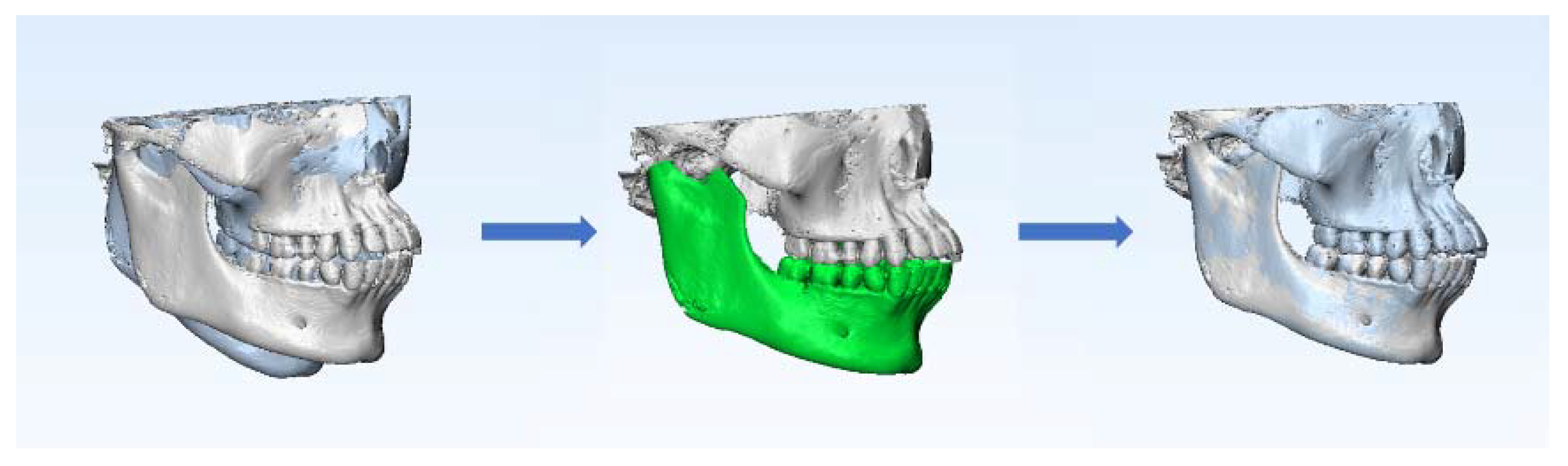
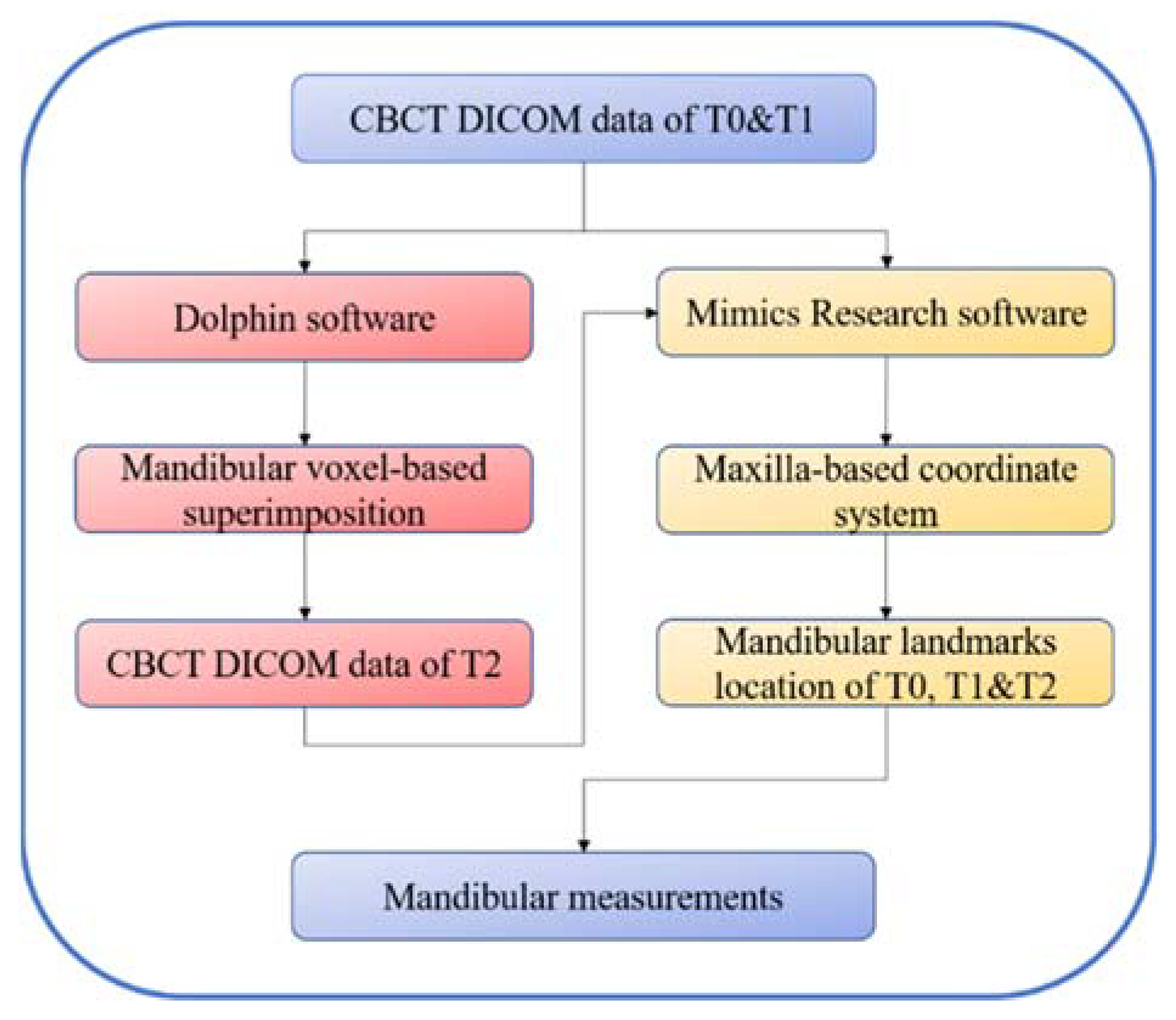
2.2. Mandibular Voxel-Based Superimposition

According to the voxel-based superimposition protocols [19], the data at T0 were set as the base volume in Dolphin software, and the data at T1 were set as the second volume. The superimposition of the two volumes involved the following three steps: Its first step was landmark-based superimposition; four landmarks were selected as reference points, namely, the most mesial points of the left and right mental foramina, and the deepest points of the left and right antegonial notches. The next step was automatic voxel-based superimposition using the registration reference area of the basal bone of the mandibular body containing no teeth or alveolar bones [20,21] (Figure 2). After that, the two volumes were automatically superimposed; meanwhile, the head orientation of the second volume was altered in accordance with the 3D position of the base volume (Figure 3). The final step was to export the second volume in DICOM multifile format, which was defined as the T2 volume.

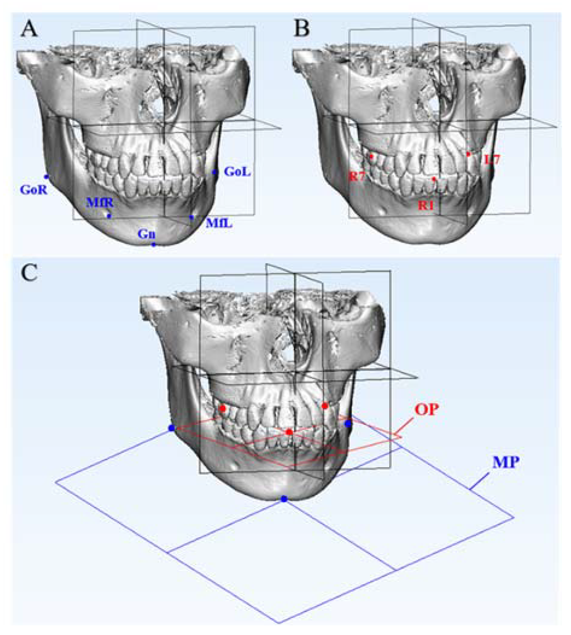
2.3. Construction of Maxilla-Based Coordinate System and Location of Mandibular Measurement Landmarks

The DICOM data at T0, T1 and T2 were then respectively imported into Mimics Research software (Version 19.0; Materialise, Leuven, Belgium). The optimal gray-value range of bone tissue in each CBCT slice was considered the threshold and was segmented. After that, the 3D models were reconstructed.
According to our former research, four maxillary landmarks (ANS, PNS, OrL and OrR) were selected as the basic coordinates to construct the maxilla-based coordinate system in the T0 and T1 models. The ANS point was defined as the origin of the coordinates. The horizontal plane (xOy) was defined as the plane passing through ANS and PNS, while parallel to the line OrL-OrR. The sagittal plane (yOz) was defined as the plane passing through ANS and PNS while perpendicular to the horizontal plane. The frontal plane (xOz) was defined as the plane passing through ANS while perpendicular to both the horizontal plane and the sagittal plane. (Table 1 and Figure 4.)
Five mandibular skeletal landmarks, three mandibular dental landmarks and two mandibular measurement planes were used to evaluate the linear and angular changes in the mandibular structures in the 3D models at T0, T1 and T2, respectively, as shown in Table 2 and Figure 5. The locating of all the maxillary and mandibular landmarks was based on sagittal, coronal and transversal slices of CBCT images and 3D models.
The schematic diagram of the process of this method is shown in Figure 6.

2.4. Data Analysis and Statistics

Firstly, the linear dimensions of maxillary basic landmarks at T0 and T1 were evaluated repeatedly to verify the accuracy and reproducibility of the maxilla-based coordinate system. The distances from ANS to PNS, from OrL to OrR, and from OrL and OrR to the xOy, xOz and yOz planes were measured.
Then, the differences in the linear and angular dimensions of the mandibular landmarks at T0 and T1 were measured. These three-dimensional differences represented the total changes after orthodontic treatment, including mandibular structural and positional changes, as simulated via the manual rearrangement of the skull and the mandible.
Next, the T2 mandible was transferred into the T0 coordinate system so that the mandibular positional changes caused by occlusal change could be eliminated. The differences in the linear and angular dimensions of the mandibular landmarks at T0 and T2 and in those at T1 and T2 were measured.
In our research study, the mandibular differences between T0 and T1 represented the total changes in the mandible, including the mandibular structural changes and positional changes. After mandibular voxel-based superimposition, the mandible at T1 was reoriented to the T2 position. Then, the differences between T0 and T2 represented the mandibular structural changes, and the differences between T1 and T2 represented the mandibular positional changes. The relationships of the differences among T0, T1 and T2 can be summarized with the following formulas:
Diff. (T0 & T1) = mandibular total changes
Diff. (T0 & T2) = mandibular structural changes
Diff. (T1 & T2) = mandibular positional changes
Diff. (T0 & T1) = Diff. (T0 & T2) + Diff. (T1 & T2)
All the operations and measurements were conducted three times each and independently by two operators under identical conditions. Statistical evaluations were performed with SPSS software (Version 22.0; IBM, Armonk, NY, USA). A paired t-test was used to evaluate the differences in the linear dimensions of the maxillary basic landmarks at T0 and T1. One-way repeated measures ANOVA and Tukey’s multiple comparisons test were used to evaluate the linear and angular changes in the mandibular structures at T0, T1 and T2. The Bland–Altman plot analysis was used for investigating the inter-observer agreement in the measurements. The intraclass correlation coefficient (ICC) was used to assess the inter- and intra-observer agreement. The threshold of statistical significance was set at 0.05.

3. Results

The linear dimensions of the maxillary basic landmarks at T0 and T1 were evaluated, and no significant differences were found (Table 3). The SDs of the measurements were all <0.7 mm, and the ICC values of the inter- and intra-observer agreement for the linear maxillary measurements were both 0.99. The results indicated great precision and reproducibility of the construction of the maxilla-based coordinate system. The Bland–Altman plot analysis was used for investigating the inter-observer agreement, which also indicated great reproducibility (Figure 7).
The linear and angular changes in the mandibular structures were measured. Comparing T0 and T1, there were increases in the distances from six out of eight mandibular landmarks to the frontal plane, which indicated the backward movement of the mandible. There were increases in the distances from all three left mandibular landmarks (L7, MfL and GoL) to the sagittal plane, while the distances from two out of three right mandibular landmarks (R7 and MfR) decreased, which indicated that the mandible deviated to the left. There were no significant differences in the positional changes in GoR. One possible reason was that the rotation center of the mandible was near GoR. The mandibular structural changes are shown in Figure 8A–C.
After mandibular voxel-based superimposition, the mandibular positional changes between T0 and T1 were transferred to the maxilla, and there were no differences in the spatial positions of the mandible between T0 and T2. After placing the mandible at T2 in the T0 maxilla coordinate system, the positional changes caused by occlusal change were eliminated, and the mandibular structural changes could be evaluated (Figure 8D–E).
In this study, the mandibular structures of the skull were stable, so there were no significant differences in the linear and angular measurements at T0 and T2. The differences between T1 and T2, which represented the mandibular positional changes, were mostly similar to the differences between T0 and T1 (Table 4, Table 5 and Table 6). The SDs of all the linear measurements were <1.0 mm, and the SDs of all the angular measurements were <0.8°. The ICC values of the inter- and intra-observer agreement for linear and angular mandibular measurements were both 0.99. The Bland–Altman plot analysis also indicated its great reproducibility (Figure 9).

4. Discussion

Our study aimed to propose a novel method to evaluate the three-dimensional mandibular structural changes. Its accuracy and reproducibility are experimentally supported by our linear and angular measurements of a skull’s mandibular structures. For simulating the orthodontic treatment, CBCT images of a skull taken pretreatment (T0) and post-treatment (T1) were collected. Then, a maxilla-based coordinate system was constructed with four maxillary basic landmarks: ANS, PNS, OrL and OrR. They were selected for their relative stability and for being easy to locate; moreover, they generally make the coordinate system clinician-friendly, as they are pervasively used in cephalometric analyses in orthodontics. ANS was defined as the origin of the coordinate system, and the line through OrL-OrR was used as a guideline to help set up the basic plane, namely, the horizontal plane (xOy) that passes through ANS and PNS while being parallel to the line OrL-OrR. After the horizontal plane was set up, the sagittal plane (yOz) and the frontal plane (xOz) could be defined. In this way, the Euclidean coordinate system was successfully constructed. In theory, this maxilla-based coordinate system could be set up for every case based on their CBCT data. Even in an orthognathic surgery case with maxillary surgery where the point of ANS may change, the cranial base could be set as reference area for maxillary superimposition so that the coordinate system at T0 is still valid and stable for measurement.
Followed by mandibular voxel-based superimposition, the differences in the mandibular structural measurements were compared among T0, T1, and T2. These differences indicated that the mandible deviated to the back side and left side, while no structural changes were observed during orthodontic treatment, which was in accordance with the manual rearrangement of the skull and the mandible.
This method is innovative in how it combines mandibular voxel-based superimposition and a maxilla-based coordinate system to successfully eliminate the pseudo positional changes caused by occlusal change and achieve precision in measuring mandibular structural changes. As a process of occlusal reconstruction, orthodontic treatment may cause changes in the spatial position of the mandible, especially in cases of functional-appliance treatment, splint therapy and orthognathic surgery [26,27,28]. Additionally, condylar position may change due to multiple factors, including ages, disc displacement and teeth extraction [29,30,31,32]. To eliminate the interference effects of mandibular positional changes on the mandibular structural changes, our solution was to superimpose two mandibles, representing the before- and after-treatment stages, and place them in the same coordinate system to calculate and compare the measurements of the mandibular structures. With this method, the mandibular structural changes could be easily calculated by comparing the mandibles at T0 and T2 in the same maxilla-based coordinate system. Meanwhile, mandibular positional changes could also be evaluated using this method. This is meaningful for functional orthopedic treatment and orthognathic surgery, in which cases the changes in mandibular morphology make it hard to distinguish between and evaluate the mandibular positional changes and structural changes. In this study, because the skull was stable, there should have been no differences between T0 and T2; hence, the differences between T0 and T1 should have been equal to the differences between T1 and T2. This was supported by our measurements.
Another innovative advantage of this method is that it allows researchers to directly evaluate and compare the structural changes in the maxilla and mandible in a same coordinate system, which further means they could share the same 3D vectors. This is potentially beneficial for some clinical research studies. For example, considering that the force of Class II elastics would affect both maxillary and mandibular dentition, to measure and analyze the changes in maxillary and mandibular dentitions with the same reference standard could be helpful for understanding the three-dimensional force components of Class II elastics and their effects. This advantage is meaningful for functional orthopedic treatment and orthognathic surgery. The method remains applicable even for some cases where growth factors or orthopedic surgery may cause maxillary structural changes and interfere with the construction of the T1 maxilla. Theoretically, in these cases, the T0 coordinate system is still set as the basic coordinate system; the maxillary voxel-based superimposition at T1 is conducted using the anterior cranial base as reference [33,34]; the combination with the mandibular voxel-based superimposition we propose is conducted; then, maxillary and mandibular structural changes can be directly compared with the same reference standard. Besides its usefulness for clinical research, the unification of the 3D vectors between the maxilla and mandible is potentially conductive for the digital industrial manufacturing of oral medicine.
Recently, most of the research studies in orthodontics utilize CBCT images for three-dimensional measurements for their good reliability, as well as in prosthodontics, dental implantology, and oral and maxillofacial surgery [35,36]. However, there is no standard method for their measurement. There are three primary methods. First, some researchers directly locate the anatomic skeletal and dental landmarks on CBCT images with proper view sections to measure the linear dimensions between these landmarks [37,38,39,40]. However, this method can only provide linear measurements between certain landmarks but not a three-dimensional treatment assessment of treatment effects on dental and skeletal structures. Additionally, the reproducibility and accuracy of this method may not be good enough considering that the precision of the results is influenced by whether the chosen view sections are proper.
The second method is to set up a coordinate system that can provide 3D vectors for three-dimensional measurements [41,42,43]. Most of the coordinate systems are based on maxillary landmarks or planes. Under the interference effects of mandibular positional changes, these systems cannot provide an accurate assessment of mandibular structural changes. The rest of the coordinate systems are constructed with mandibular skeletal landmarks [14]. Although it would not be interfered with by mandibular positional changes, this type of system is restricted to measuring mandibular structural changes. In other words, there is no single coordinate system that can measure mandibular structural changes without interference effects while also measuring maxillary structural changes at the same time. To create such system is needed, as it would enable us to directly compare the maxillary and mandibular structural changes with the same 3D vectors.
With the third method, some researchers superimpose the maxillary and mandibular structures before and after treatment to exhibit and evaluate their changes [44,45,46]. They reconstruct the 3D models and then use the landmark-based, surface-based or voxel-based method to superimpose the models and compare their differences. Unfortunately, superimposition alone normally uses color maps to compare the structural changes, and it provides primarily qualitative data but insufficient 3D quantitative analysis. As it cannot decompose and express the differences in the three dimensions with proper vectors as reference standards, it is unsatisfactory in reaching a comprehensive understanding of three-dimensional treatment effects. Although some measurement software could provide a 3D vector with its equipped common coordinate system, researchers would still have to conduct an additional step to manually reorient the head position [18,47], which is time-consuming. In addition, it is less researcher-friendly in that the accuracy of its results is overtly dependent on the great precision of manual head reorientation. Additionally, when it comes to measuring the structural changes and comparing those changes between different cases, it could be uneasy to use and to give sufficiently clear results, as software coordinate systems has no origin of coordinates and actual coordinate planes.
This study had some limitations. Firstly, only one dry human skull was selected; two CBCT records were obtained; and measurements were repeated for analysis six times. The reason was that the purpose of this study was to explore a possible method for clinical research. Using one dry skull as the research object could avoid the interference of confounding factors in the study. Secondly, the analysis of the changes occurring during treatment was based on a simulation, and the accuracy and validity of this method were theoretically proved by previous works but not fully validated. Therefore, we remind readers that in clinical settings, relevant interference is usually ineluctable and that the results of this study should be treated with great caution. In our future work, we aim to expand the samples’ quantity and focus on practical clinical situations.
Taking all the above into consideration, the proposed method has several advantages. It is time-saving and user-friendly and shows great accuracy, reproducibility and validity. The radiation dose of its needed CBCT images could be relatively low; the imaging field of its CBCT images is only expected to cover the cranial and maxillofacial skeletal structures from the orbitales to the mandibular body; hence, the medium field of view would be enough [48,49]. Moreover, theoretically, there would be no need for precise head orientation because the coordinate system is constructed with certain maxillary basic landmarks and has great reproducibility. This method could be helpful for clinical research that involves the description of the mandibular structural and positional changes and the comparison between maxillary and mandibular structural changes. It can be applied in orthodontics to assess three-dimensional treatment effects, as well as in prosthodontics, dental implantology, and oral and maxillofacial surgery treatment analyses.

5. Conclusions

A systematic method that combines a maxilla-based coordinate system and mandibular voxel-based superimposition is proposed in this study. It not only enables us to accurately evaluate the mandibular structural and positional changes, but it can also be used to directly compare the maxillary and mandibular structural changes with the same reference standard.

Author Contributions

Conceptualization, methodology and writing—review and editing, W.L.; project administration and writing—review and editing, Z.Z.; methodology, investigation and writing—original draft, C.Z.; data curation and investigation, L.J.; resources and investigation, Y.L.; Resources and graphics, F.P. All authors have read and agreed to the published version of the manuscript.

Funding

This research study was funded by Sichuan Science and Technology Program (2020ZDZX0031), Sichuan University—Align Technology Clinical Research Foundation (No. 21H0446), and Angelalign Scientific Research Fund (No. SDTS21-3-21 & SDTS21-5-14).

Institutional Review Board Statement

Not applicable.

Informed Consent Statement

Not applicable.

Data Availability Statement

Data can be provided upon reasonable request from the corresponding author.

Conflicts of Interest

The authors declare no conflict of interest.

References

  1. Venkatesh, E.; Elluru, S.V. Cone beam computed tomography: Basics and applications in dentistry. J. Istanb. Univ. Fac. Dent. 2017, 51, S102–S121. [Google Scholar] [CrossRef] [PubMed]
  2. Takei, Y.; Monzen, H.; Matsumoto, K.; Hanaoka, K.; Tamura, M.; Nishimura, Y. Registration accuracy with the low dose kilovoltage cone-beam CT: A phantom study. BJR Open 2019, 1, 20190028. [Google Scholar] [CrossRef] [PubMed]
  3. Feng, B.; Wang, Y.; Ouyang, W.; Yu, M.; Wang, H. Construction and validity of a midsagittal plane based on the symmetry of a 3-dimensional model of the relevant cranial base. Am. J. Orthod. Dentofac. Orthop. 2021, 159, e49–e58. [Google Scholar] [CrossRef] [PubMed]
  4. Lee, Y.J.; Kook, Y.A.; Park, J.H.; Park, J.; Bayome, M.; Vaid, N.R.; Kim, Y. Short-term cone-beam computed tomography evaluation of maxillary third molar changes after total arch distalization in adolescents. Am. J. Orthod. Dentofac. Orthop. 2019, 155, 191–197. [Google Scholar] [CrossRef] [PubMed]
  5. Kheir, N.A.; Kau, C.H. Measuring mandibular asymmetry in Class I normal subjects using 3D novel coordinate system. Ann. Maxillofac. Surg. 2014, 4, 34–38. [Google Scholar]
  6. Kim, N.K.; Lee, C.; Kang, S.H.; Park, J.W.; Kim, M.J.; Chang, Y.I. A three-dimensional analysis of soft and hard tissue changes after a mandibular setback surgery. Comput. Methods Programs Biomed. 2006, 83, 178–187. [Google Scholar] [CrossRef]
  7. Pan, F.; Yang, Z.; Wang, J.; Cai, R.; Liu, J.; Zhang, C.; Liao, W. Influence of orthodontic treatment with premolar extraction on the spatial position of maxillary third molars in adult patients: A retrospective cohort cone-bean computed tomography study. BMC Oral Health 2020, 20, 321. [Google Scholar] [CrossRef]
  8. Guichet, N.F. Biologic laws governing functions of muscles that move the mandible. Part III. Speed of closure--manipulation of the mandible. J. Prosthet. Dent. 1977, 38, 174–179. [Google Scholar] [CrossRef]
  9. Griffin, C.J.; Hawthorn, R.; Harris, R. Anatomy and histology of the human temporomandibular joint. Monogr. Oral Sci. 1975, 4, 1–26. [Google Scholar]
  10. Freitas, K.M.; Janson, G.; Tompson, B.; de Freitas, M.R.; Simão, T.M.; Valarelli, F.P.; Cançado, R.H. Posttreatment and physiologic occlusal changes comparison. Angle Orthod. 2013, 83, 239–245. [Google Scholar] [CrossRef]
  11. Bombonatti, R.; Aliaga-Del Castillo, A.; Bombonatti, J.F.S.; Garib, D.; Tompson, B.; Janson, G. Cephalometric and occlusal changes of Class III malocclusion treated with or without extractions. Dent. Press. J. Orthod. 2020, 25, 24–32. [Google Scholar] [CrossRef] [PubMed]
  12. Bozkurt, A.P.; Aras, I.; Othman, E.; Aras, A. Comparison of 2 treatment protocols using fixed functional appliances in Class II malocclusion: Treatment results and stability. Am. J. Orthod. Dentofac. Orthop. 2020, 157, 474–480. [Google Scholar] [CrossRef] [PubMed]
  13. Moshiri, S.; Araújo, E.A.; McCray, J.F.; Thiesen, G.; Kim, K.B. Cephalometric evaluation of adult anterior open bite non-extraction treatment with Invisalign. Dent. Press. J. Orthod. 2017, 22, 30–38. [Google Scholar] [CrossRef]
  14. Pittayapat, P.; Jacobs, R.; Bornstein, M.M.; Odri, G.A.; Kwon, M.S.; Lambrichts, I.; Willems, G.; Politis, C.; Olszewski, R. A new mandible-specific landmark reference system for three-dimensional cephalometry using cone-beam computed tomography. Eur. J. Orthod. 2016, 38, 563–568. [Google Scholar] [CrossRef] [PubMed]
  15. Almukhtar, A.; Ju, X.; Khambay, B.; McDonald, J.; Ayoub, A. Comparison of the accuracy of voxel based registration and surface based registration for 3D assessment of surgical change following orthognathic surgery. PLoS ONE 2014, 9, e93402. [Google Scholar]
  16. Äner, S.T.; Kanavakis, G.; Matthey, F.; Gkantidis, N. Voxel-based superimposition of serial craniofacial CBCTs: Reliability, reproducibility and segmentation effect on hard-tissue outcomes. Orthod. Craniofac. Res. 2020, 23, 92–101. [Google Scholar]
  17. Ghoneima, A.; Cho, H.; Farouk, K.; Kula, K. Accuracy and reliability of landmark-based, surface-based and voxel-based 3D cone-beam computed tomography superimposition methods. Orthod. Craniofac. Res. 2017, 20, 227–236. [Google Scholar] [CrossRef] [PubMed]
  18. Wei, R.Y.; Atresh, A.; Ruellas, A.; Cevidanes, L.H.S.; Nguyen, T.; Larson, B.E.; Mangum, J.E.; Manton, D.J.; Schneider, P.M. Three-dimensional condylar changes from Herbst appliance and multibracket treatment: A comparison with matched Class II elastics. Am. J. Orthod. Dentofac. Orthop. 2020, 158, 505–517.e6. [Google Scholar] [CrossRef]
  19. Haas Junior, O.L.; Guijarro-Martínez, R.; Sousa Gil, A.P.; Méndez-Manjón, I.; Valls-Otañón, A.; de Oliveira, R.B.; Hernández-Alfaro, F. Cranial Base Superimposition of Cone-Beam Computed Tomography Images: A Voxel-Based Protocol Validation. J. Craniofac. Surg. 2019, 30, 1809–1814. [Google Scholar] [CrossRef]
  20. Ruellas, A.C.; Yatabe, M.S.; Souki, B.Q.; Benavides, E.; Nguyen, T.; Luiz, R.R.; Franchi, L.; Cevidanes, L.H. 3D Mandibular Superimposition: Comparison of Regions of Reference for Voxel-Based Registration. PLoS ONE 2016, 11, e0157625. [Google Scholar] [CrossRef]
  21. Nguyen, T.; Cevidanes, L.; Franchi, L.; Ruellas, A.; Jackson, T. Three-dimensional mandibular regional superimposition in growing patients. Am. J. Orthod. Dentofac. Orthop. 2018, 153, 747–754. [Google Scholar] [CrossRef] [PubMed]
  22. Song, K.T.; Park, J.H.; Moon, W.; Chae, J.M.; Kang, K.H. Three-dimensional changes of the zygomaticomaxillary complex after mini-implant assisted rapid maxillary expansion. Am. J. Orthod. Dentofacial. Orthop. 2019, 156, 653–662. [Google Scholar] [CrossRef] [PubMed]
  23. Chen, G.; Al Awadi, M.; Chambers, D.W.; Lagravère-Vich, M.O.; Xu, T.; Oh, H. The three-dimensional stable mandibular landmarks in patients between the ages of 12.5 and 17.1 years. BMC Oral Health 2020, 20, 153. [Google Scholar] [CrossRef]
  24. Noh, H.K.; Park, H.S. Does maxillary yaw exist in patients with skeletal Class III facial asymmetry? Am. J. Orthod. Dentofac. Orthop. 2021, 160, 573–587. [Google Scholar] [CrossRef] [PubMed]
  25. Kang, S.H.; Byun, I.Y.; Kim, J.H.; Park, H.K.; Kim, M.K. Three-dimensional anatomic analysis of mandibular foramen with mandibular anatomic landmarks for inferior alveolar nerve block anesthesia. Oral Surg Oral Med Oral Pathol Oral Radiol 2013, 115, e17–e23. [Google Scholar] [CrossRef] [PubMed]
  26. Ishaq, R.A.; AlHammadi, M.S.; Fayed, M.M.; El-Ezz, A.A.; Mostafa, Y. Fixed functional appliances with multibracket appliances have no skeletal effect on the mandible: A systematic review and meta-analysis. Am. J. Orthod. Dentofac. Orthop. 2016, 149, 612–624. [Google Scholar] [CrossRef]
  27. Lee, G.H.; Park, J.H.; Moon, D.N.; Lee, S.M. Protocols for orthodontic treatment of patients with temporomandibular joint disorders. Am. J. Orthod. Dentofac. Orthop. 2021, 159, 373–388. [Google Scholar] [CrossRef]
  28. Han, J.J.; Jung, S.; Park, H.J.; Oh, H.K.; Kook, M.S. Evaluation of Postoperative Mandibular Positional Changes After Mandibular Setback Surgery in a Surgery-First Approach: Isolated Mandibular Surgery Versus Bimaxillary Surgery. J. Oral Maxillofac. Surg. 2019, 77, 181.e1–181.e12. [Google Scholar] [CrossRef]
  29. Sreelal, T.; Janardanan, K.; Nair, A.S.; Nair, A.S. Age changes in horizontal condylar angle: A clinical and cephalometric study. J. Indian Prosthodont. Soc. 2013, 13, 108–112. [Google Scholar] [CrossRef]
  30. Kattiney de Oliveira, L.; Fernandes Neto, A.J.; Moraes Mundim Prado, I.; Guimarães Henriques, J.C.; Beom Kim, K.; de Araújo Almeida, G. Evaluation of the condylar position in younger and older adults with or without temporomandibular symptoms by using cone beam computed tomography. J. Prosthet. Dent. 2022, 127, 445–452. [Google Scholar] [CrossRef]
  31. Ikeda, K.; Kawamura, A. Disc displacement and changes in condylar position. Dentomaxillofac. Radiol. 2013, 42, 84227642. [Google Scholar] [CrossRef] [PubMed]
  32. Alhammadi, M.S.; Fayed, M.S.; Labib, A. Three-dimensional assessment of condylar position and joint spaces after maxillary first premolar extraction in skeletal Class II malocclusion. Orthod. Craniofac. Res. 2017, 20, 71–78. [Google Scholar] [CrossRef] [PubMed]
  33. Weissheimer, A.; Menezes, L.M.; Koerich, L.; Pham, J.; Cevidanes, L.H. Fast three-dimensional superimposition of cone beam computed tomography for orthopaedics and orthognathic surgery evaluation. Int. J. Oral Maxillofac. Surg. 2015, 44, 1188–1196. [Google Scholar] [CrossRef]
  34. Cevidanes, L.H.; Motta, A.; Proffit, W.R.; Ackerman, J.L.; Styner, M. Cranial base superimposition for 3-dimensional evaluation of soft-tissue changes. Am. J. Orthod. Dentofac. Orthop. 2010, 137, S120–S129. [Google Scholar] [CrossRef] [Green Version]
  35. Scarfe, W.C.; Azevedo, B.; Toghyani, S.; Farman, A.G. Cone Beam Computed Tomographic imaging in orthodontics. Aust. Dent. J. 2017, 62, 33–50. [Google Scholar] [CrossRef]
  36. Anderson, P.J.; Yong, R.; Surman, T.L.; Rajion, Z.A.; Ranjitkar, S. Application of three-dimensional computed tomography in craniofacial clinical practice and research. Aust. Dent. J. 2014, 59, 174–185. [Google Scholar] [CrossRef] [PubMed]
  37. Nucera, R.; Lo Giudice, A.; Bellocchio, A.M.; Spinuzza, P.; Caprioglio, A.; Perillo, L.; Matarese, G.; Cordasco, G. Bone and cortical bone thickness of mandibular buccal shelf for mini-screw insertion in adults. Angle Orthod. 2017, 87, 745–751. [Google Scholar] [CrossRef] [PubMed]
  38. Papadopoulou, A.K.; Papageorgiou, S.N.; Hatzopoulos, S.A.; Tsirlis, A.; Athanasiou, A.E. Alveolar ridge alterations in the maxillary anterior region after tooth extraction through orthodontic forced eruption for implant site development: A clinical CBCT study. Eur. J. Orthod. 2020, 42, 295–304. [Google Scholar] [CrossRef] [PubMed]
  39. Sun, L.; Yuan, L.; Wang, B.; Zhang, L.; Shen, G.; Fang, B. Changes of alveolar bone dehiscence and fenestration after augmented corticotomy-assisted orthodontic treatment: A CBCT evaluation. Prog. Orthod. 2019, 20, 7. [Google Scholar] [CrossRef]
  40. Becker, K.; Unland, J.; Wilmes, B.; Tarraf, N.E.; Drescher, D. Is there an ideal insertion angle and position for orthodontic mini-implants in the anterior palate? A CBCT study in humans. Am. J. Orthod. Dentofac. Orthop. 2019, 156, 345–354. [Google Scholar] [CrossRef]
  41. Shibata, M.; Nawa, H.; Kise, Y.; Fuyamada, M.; Yoshida, K.; Katsumata, A.; Ariji, E.; Goto, S. Reproducibility of three-dimensional coordinate systems based on craniofacial landmarks: A tentative evaluation of four systems created on images obtained by cone-beam computed tomography with a large field of view. Angle Orthod. 2012, 82, 776–784. [Google Scholar] [CrossRef] [PubMed]
  42. Yoon, S.J.; Wang, R.F.; Na, H.J.; Palomo, J.M. Normal range of facial asymmetry in spherical coordinates: A CBCT study. Imaging Sci. Dent. 2013, 43, 31–36. [Google Scholar] [CrossRef] [PubMed]
  43. Park, K.R.; Park, H.S.; Piao, Z.; Kim, M.K.; Yu, H.S.; Seo, J.K.; Lee, S.H. Three-dimensional vector analysis of mandibular structural asymmetry. J. Craniomaxillofac. Surg. 2013, 41, 338–344. [Google Scholar] [CrossRef]
  44. Leonardi, R.M.; Aboulazm, K.; Giudice, A.L.; Ronsivalle, V.; D’Antò, V.; Lagravère, M.; Isola, G. Evaluation of mandibular changes after rapid maxillary expansion: A CBCT study in youngsters with unilateral posterior crossbite using a surface-to-surface matching technique. Clin. Oral Investig. 2021, 25, 1775–1785. [Google Scholar] [CrossRef] [PubMed]
  45. Claus, J.D.P.; Koerich, L.; Weissheimer, A.; Almeida, M.S.; Belle de Oliveira, R. Assessment of condylar changes after orthognathic surgery using computed tomography regional superimposition. Int. J. Oral Maxillofac. Surg. 2019, 48, 1201–1208. [Google Scholar] [CrossRef]
  46. Muraglie, S.; Leonardi, R.; Aboulazm, K.; Stumpo, C.; Loreto, C.; Grippaudo, C. Evaluation of structural skeletal asymmetry of the glenoid fossa in adult patients with unilateral posterior crossbite using surface-to-surface matching on CBCT images. Angle Orthod. 2020, 90, 376–382. [Google Scholar] [CrossRef]
  47. Ruellas, A.C.; Tonello, C.; Gomes, L.R.; Yatabe, M.S.; Macron, L.; Lopinto, J.; Goncalves, J.R.; Garib Carreira, D.G.; Alonso, N.; Souki, B.Q.; et al. Common 3-dimensional coordinate system for assessment of directional changes. Am. J. Orthod. Dentofac. Orthop. 2016, 149, 645–656. [Google Scholar] [CrossRef]
  48. Elshenawy, H.; Aly, W.; Salah, N.; Nasry, S.; Anter, E.; Ekram, K. Influence of Small, Midi, Medium and Large Fields of View on Accuracy of Linear Measurements in CBCT Imaging: Diagnostic Accuracy Study. Open Access Maced. J. Med. Sci. 2019, 7, 1037–1041. [Google Scholar] [CrossRef]
  49. Little, D.P. Image quality improvement for medium and large field of view Elekta XVI scans. Australas. Phys. Eng. Sci. Med. 2019, 42, 1153–1164. [Google Scholar] [CrossRef]
Figure 1. A human skull specimen was selected as the research object.
Jcm 11 05229 g001
Figure 2. The automatic voxel-based superimposition using the registration reference area of the basal bone of the mandibular body containing no teeth nor alveolar bones.
Jcm 11 05229 g002
Figure 3. Process of mandibular voxel-based superimposition between T0 and T1. The white skull is the 3D model at T0. The blue skull is the 3D model at T1. The green area is the registration reference area of mandibular voxel-based superimposition.
Jcm 11 05229 g003
Figure 4. The construction of the maxilla-based coordinate system was based on four basic landmarks: ANS, PNS, OrL and OrR. The ANS point was defined as the origin of the coordinates. The black points are these four basic maxillary landmarks.
Jcm 11 05229 g004
Figure 5. Mandibular measurement landmarks and planes. (A) The blue points are five mandibular skeletal landmarks: MfL, MfR, GoL, GoR and Gn. (B) The red points are three mandibular dental landmarks: R1, L7 and R7. (C) The blue plane is the mandibular plane constructed by Gn, GoL and GoR. The red plane is the occlusal plane constructed by R1, L7 and R7.
Jcm 11 05229 g005
Figure 6. Schematic diagram of the process of this method. T0, before treatment; T1, after treatment, which was simulated via mandibular rearrangement; T2, after mandibular voxel-based superimposition on T1 CBCT data.
Jcm 11 05229 g006
Figure 7. Bland–Altman plot analysis was used for investigating the inter-observer agreement in locating the maxillary basic landmarks and measuring the linear dimensions, which indicated great reproducibility in constructing the maxilla-based coordinate system.
Jcm 11 05229 g007
Figure 8. The position changes among T0, T1 and T2. (A) The white skull is the 3D model at T0. (B) The blue skull is the 3D model at T1. (C) Differences in the spatial positions of the mandible between T0 and T1, which included mandibular structural changes and mandibular positional changes caused by occlusal change. (D) The red skull is the 3D model at T2. After mandibular voxel-based superimposition, the positional changes between T0 and T1 were transferred to the maxilla, and there were no differences in the spatial positions of the mandible between T0 and T2. (E) After placing the mandible at T2 in the T0 maxilla coordinate system, the positional changes caused by occlusal change were eliminated, and the mandibular structural changes could be evaluated.
Jcm 11 05229 g008
Figure 9. The Bland–Altman plot analysis was used for investigating the inter-observer agreement in locating the mandibular measurement landmarks and measuring the linear dimensions, which indicated great reproducibility.
Jcm 11 05229 g009
Table 1. Maxillary basic landmarks and planes of the maxilla-based coordinate system.
Maxillary Basic Landmarks and Basic Planes
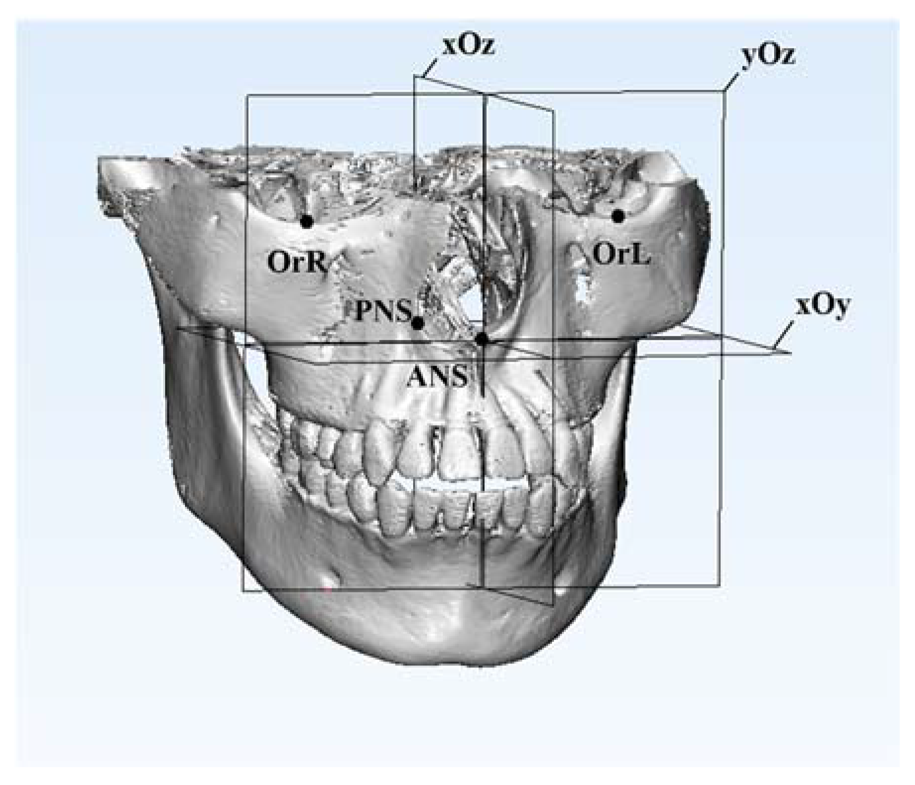
OrLThe most inferior point of the left bony orbit
OrRThe most inferior point of the left bony orbit
ANSThe tip of the anterior nasal spine
PNSThe tip of the posterior nasal spine
xOyThe horizontal plane, passing through ANS and PNS while parallel to the line OrL-OrR
yOzThe sagittal plane, passing through ANS and PNS while perpendicular to the horizontal plane
xOzThe frontal plane, passing through ANS while perpendicular to both horizontal plane and sagittal plane
The definition and location of the maxillary landmarks and planes were based on previous research studies [22,23,24].
Table 2. Mandibular measurement landmarks and planes.
Mandibular Measurement Landmarks and Planes
MfL The most anterior point of the left mental foramen
MfRThe most anterior point of the right mental foramen
GoLThe midpoint of the bony border of the left mandibular angle
GoRThe midpoint of the bony border of the right mandibular angle
GnThe intersection between the mid-sagittal plane and the most anteroinferior point of
the mandibular symphysis
R1The midpoint of the incisor edge of the mandibular right incisor
R7The mesial–buccal cusp tip of the mandibular right second molar
L7The mesial–buccal cusp tip of the mandibular left second molar
OPOcclusal plane, constructed by R1, L7 and R7
MPMandibular plane, constructed by Gn, GoL and GoR
The definition and location of the mandibular landmarks and planes were based on previous research studies [14,23,24,25].
Table 3. The linear dimensions of basic maxillary landmarks at T0 and T1.
T0T1p-Value
Mean (mm)SDMean (mm)SD
ANS-PNS46.80.3547.040.660.4496
OrL-OrR64.960.6464.90.60.8645
OrL to horiz22.980.1223.020.250.7375
OrL to sagit33.60.3533.970.480.1549
OrL to front15.730.2715.760.280.854
OrR to horiz22.980.1223.020.250.7375
OrR to sagit31.320.5330.890.450.1591
OrR to front18.150.3918.070.460.7452
T0, before treatment; T1, after treatment, which was simulated via mandibular rearrangement; OrL, left orbitale; OrR, right orbitale; PNS, posterior nasal spine; horiz, horizontal plane; sagit, sagittal plane; front, frontal plane.
Table 4. Linear changes in mandibular dental landmarks among T0, T1 and T2.
T0 T1 T2 p-Value
Mean (mm)SDMean (mm)SDMean (mm)SDT0 vs. T1T1 vs. T2T0 vs. T2
L7 to horiz22.090.2322.270.1622.170.180.2910.6640.774
L7 to sagit26.930.3228.350.29270.20.000 ***0.000 ***0.888
L7 to front36.620.4338.40.2636.570.240.000 ***0.000 ***0.956
R7 to horiz21.830.321.810.3321.80.310.9960.9970.987
R7 to sagit25.240.423.610.4624.810.550.000 ***0.002 **0.293
R7 to front41.360.25420.3441.250.340.008 **0.002 **0.803
R1 to horiz30.540.1931.080.1530.630.230.001 ***0.003 **0.747
R1 to sagit2.740.480.710.392.760.340.000 ***0.000 ***0.995
R1 to front0.710.170.860.130.890.240.3940.9620.273
T0, before treatment; T1, after treatment, which was simulated via mandibular rearrangement; T2, after mandibular voxel-based superimposition on T1 CBCT data; L7, left mandibular second molar; R7, right mandibular second molar; R1, right mandibular central incisor; horiz, horizontal plane; sagit, sagittal plane; front, frontal plane; ** p ˂ 0.01; *** p ˂ 0.001.
Table 5. The linear changes in mandibular skeletal landmarks at T0, T1 and T2.
T0 T1 T2 p-Value
Mean (mm)SDMean (mm)SDMean (mm)SDT0 vs. T1T1 vs. T2T0 vs. T2
MfL to horiz53.150.3353.060.4153.030.20.8880.9870.812
MfL to sagit22.350.2824.10.4822.360.430.000 ***0.000 ***0.999
MfL to front24.750.427.120.1624.760.370.000 ***0.000 ***0.999
MfR to horiz51.320.451.840.451.420.240.0540.1360.867
MfR to sagit21.680.3420.370.1521.690.370.000 ***0.000 ***0.999
MfR to front28.960.1930.130.2829.080.360.000 ***0.000 ***0.76
GoL to horiz35.310.7635.420.2635.60.350.9320.8180.608
GoL to sagit48.990.4549.880.2549.190.310.001 **0.010 **0.604
GoL to front74.910.7376.570.474.460.330.000 ***0.000 ***0.315
GoR to horiz35.040.5534.740.4835.260.720.6510.2960.792
GoR to sagit39.480.5539.120.5139.240.60.5190.9240.746
GoR to front83.80.384.20.983.470.580.5390.150.647
Gn to horiz66.090.4166.710.2766.230.40.027 *0.0870.805
Gn to sagit0.610.280.910.440.740.440.4260.7480.848
Gn to front18.260.3820.770.518.650.550.000 ***0.000 ***0.362
T0, before treatment; T1, after treatment, which was simulated via mandibular rearrangement; T2, after mandibular voxel-based superimposition on T1 CBCT data; MfL, left mental foramen; MfR, right mental foramen; GoL, left gonion; GoR, right gonion; Gn, gnathion; horiz, horizontal plane; sagit, sagittal plane; front, frontal plane; * p ˂ 0.05; ** p ˂0.01; *** p ˂0.001.
Table 6. Angular changes in mandibular measurement planes at T0, T1 and T2.
T0 T1 T2 p-Value
Mean (°)SDMean (°)SDMean (°)SDT0 vs. T1T1 vs. T2T0 vs. T2
OP with horiz12.160.2412.910.1912.240.330.000 ***0.001 **0.851
OP with sagit89.190.2689.610.4389.240.210.0790.1270.961
OP with front77.880.2477.10.1977.790.330.000 ***0.001 **0.83
MP with horiz26.750.4427.890.4726.950.710.008 **0.026 *0.811
MP with sagit87.580.4188.10.2287.560.410.0640.0510.992
MP with front63.380.4362.190.4963.180.740.007 **0.022 *0.823
OP with horiz12.160.2412.910.1912.240.330.000 ***0.001 **0.851
OP with sagit89.190.2689.610.4389.240.210.0790.1270.961
OP with front77.880.2477.10.1977.790.330.000 ***0.001 **0.83
T0, before treatment; T1, after treatment, which was simulated via mandibular rearrangement; T2, after mandibular voxel-based superimposition on T1 CBCT data; OP, occlusal plane; MP, mandibular plane; horiz, horizontal plane; sagit, sagittal plane; front, frontal plane; * p ˂ 0.05; ** p ˂ 0.01; *** p ˂ 0.001.
Publisher’s Note: MDPI stays neutral with regard to jurisdictional claims in published maps and institutional affiliations.

