1. Introduction
Hydrogen, as an energy carrier, represents a promising solution for problems related to current fuel-based energy system [
1]. It provides a sustainable fuel for a wide range of applications, from transportation to small electronic devices or stationary applications. Among other methods, one way, if not the only way, to produce green H
2 is water electrolysis, if electrical input is obtained from a renewable energy (RE) source. For this reason, in the past decades, great attention on combination RE-H
2 technologies was paid by energy companies, to set themselves in the future markets of distributed power generation and alternative fuels [
2].
From a technical point of view, different technologies may be considered to perform water electrolysis, such as: Alkaline (AWE), proton exchange membranes (PEMWE), and solid oxide (SOWE) electrolysis. Among them, AWE is considered an optimal solution for RE combination, because it is the most economical and mature technology for H
2 electrochemical production, especially at a large scale [
3]. In fact, the largest water electrolysis systems are, nowadays, alkaline electrolyzers. Currently, AWE systems of up to 6MW are commercially available [
4].
As the energetic requirement for water electrolysis is considered, most of the energy input is due to the high activation losses of the reactions involved at the electrodes, as well as to ohmic losses related to bubbles formation and to the charge transfer process within the electrolyte and separator. However, due to the very high concentration of the electrolyte used in alkaline electrolysis (25–32% KOH w/w), ohmic drop through the separator represents one of the points of great concern [
5]. It is worth noting the crucial role of separator, since it must ensure the separation between gases (to avoid explosive mixtures) and, at the same time, favor the OH
− ions transport. In this context, improving the ionic conductivity of the separator could be one of the possible strategies to make the whole process more efficient.
Up to the end of the 20th century, asbestos was the most used material; however, its use was eventually forbidden by the European Commission because of its potential health risk [
6]. Moreover, some authors reported the low chemical resistance of this material to strong alkaline media [
7]. Candidates for asbestos substitution should have such suitable characteristics as: Low resistance, good mechanical stability, high corrosion resistance, long lifetime, low H
2 crossover and, finally, being economically acceptable [
8]. Different materials have been proposed and tested this aim, such as ion-exchange polymeric membranes, made on conductive materials and functionalized for separating ions from solution. The application of these membranes in AWE has not been successful, mainly due to the poor chemical stability of the materials in strong alkali media, but also to membrane fouling [
9].
On the other hand, ceramic-based diaphragms are considered a better alternative [
10,
11]. Ceramic diaphragms are microporous components, made of non-conductor material, which should act as a physic barrier, allowing the charge transport through micro-channels and, in turn, the ionic conduction between cathodic and anodic chambers. Recently, the interest for ceramic diaphragms for AWE has increased, and different ceramic materials have been tested, such as: Alumina-Kaolin [
9,
10], Wollastinite, and Olivine [
11], ZrO
2 [
12], etc.
Considering the specific characteristics of diaphragms, determining their resistivity is not simple: Unlike ionic membranes, diaphragms are not functionalized, and their conductivity is only due to ions of electrolyte in the micro-channels. Calculating this parameter is more critical when working with very porous materials in high conducting media, because the ionic resistivity of the electrolyte and diaphragm could present low and very similar values. In this case, even small experimental errors can heavily affect the results.
Different methodologies were proposed in the literature to determine the resistivity of diaphragms [
13,
14,
15,
16]. Typically, in these techniques, the resistance of the separator is obtained as a difference between the resistances of the system, measured in the presence, and in absence of, the separator, respectively. However, since many experiments are required in this procedure, the correction could cause of increasing errors. Moreover, electrochemical methods for resistance determination vary depending on DC or AC measurements. AC techniques are expected to be more accurate, although expensive and more precise instrumentation is required. On the other hand, as far as we know, there are no proposed methodologies, which allow the direct calculation of the conductivity of channels for diaphragms. In the case of ion exchange membranes, ionic conductivity is usually calculated by direct determination methods, based on direct (DC) [
9,
13] or alternating current (AC) [
14], with two [
15] or four electrodes [
16]. However, the application of these methodologies for diaphragms could be more difficult because of cell architecture or electrolyte retention limitations.
Furthermore, to the best of our knowledge, there are no studies in the literature, which compare different electrochemical methods for calculating the resistance contribution of diaphragms in AWE applications. Then, the selection of one or another approach can be more influenced by the instrumentation availability, than technique accuracy.
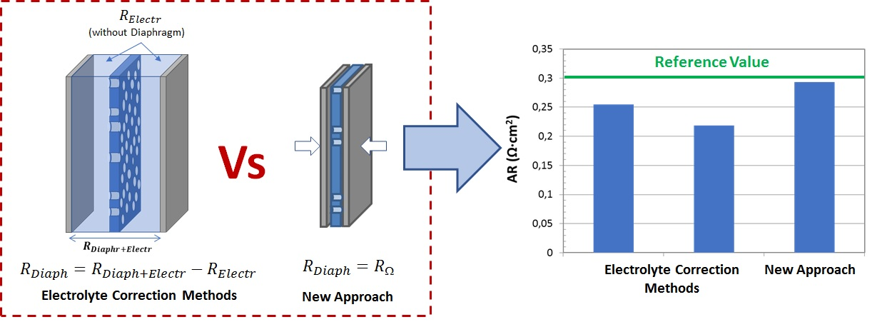
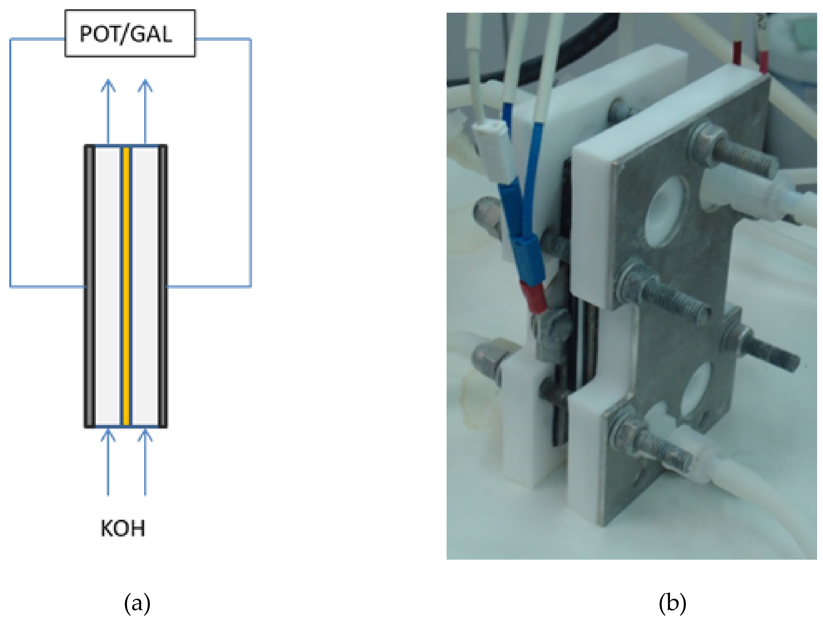
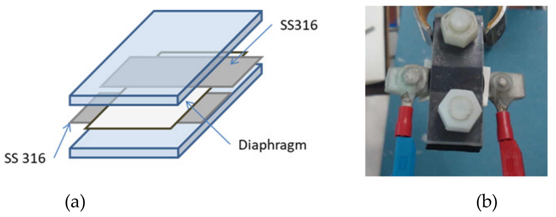
For these reasons, in the present work, we propose a simple approach to measure the ionic resistance contribution of diaphragms for AWE applications. An optimized technique has been designed to reduce the typical error sources identified in other methodologies. To this aim, the presented approach is based on:
Reducing resistance sources: Direct contact between electrodes and diaphragm eliminates the resistance contribution of electrolyte in the bulk.
Direct measurement: The studied approach is based on electrochemical methodologies for determining the ionic resistance of polymeric membranes. In these approaches, electrodes are in direct contact with the membrane.
Electrochemical Impedance Spectroscopy (EIS) measurements: AC measurements are more accurate than DC ones. Because of this, EIS techniques are used instead of chronopotentiometry or other DC techniques.
Easy technical approach: Cell and components are manufactured with cheap materials, resulting in an economical set-up.
Accuracy, reproducibility and precision of this simple method were tested by determining the resistivity of Zirfon® (AGFA, Mortsel, Belgium), which is the conventional commercial material for AWE diaphragms. In order to evaluate the convenience of the proposed approach, the results were compared with those obtained in previous works, from typical methods based on DC and AC measurements.
The methodology presented in this paper showed the best results in terms of higher precision and lower error.
3. Results and Discussion
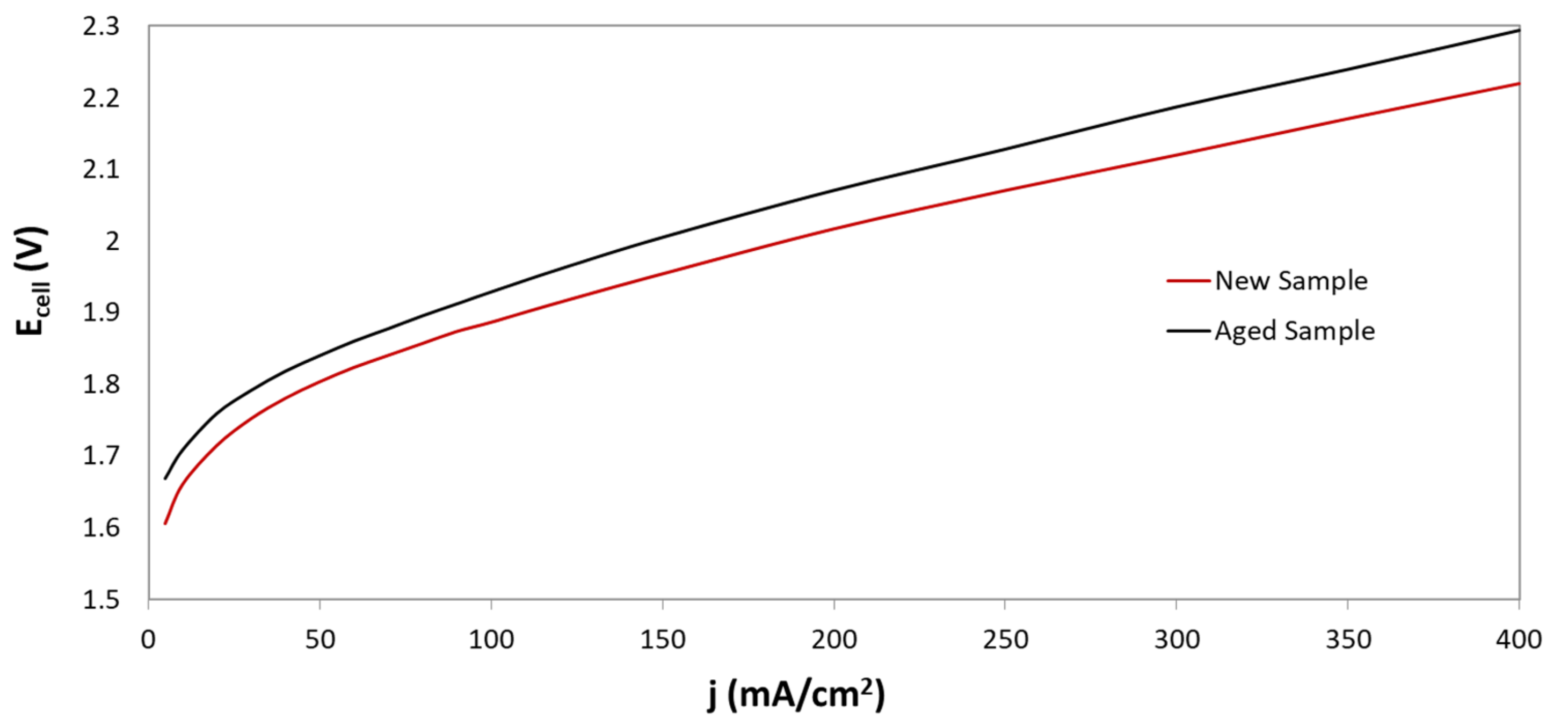
During long operation, electrolysis cell progressively tends to reduce its performance, as can be observed in
Figure 7. In fact, by comparing the response of the cell with new and aged samples, it can be seen that the deterioration of electrochemical performance is presented at both low, and high, current densities. For instance, for current densities values of 100 mA/cm
2 and 400 mA/cm
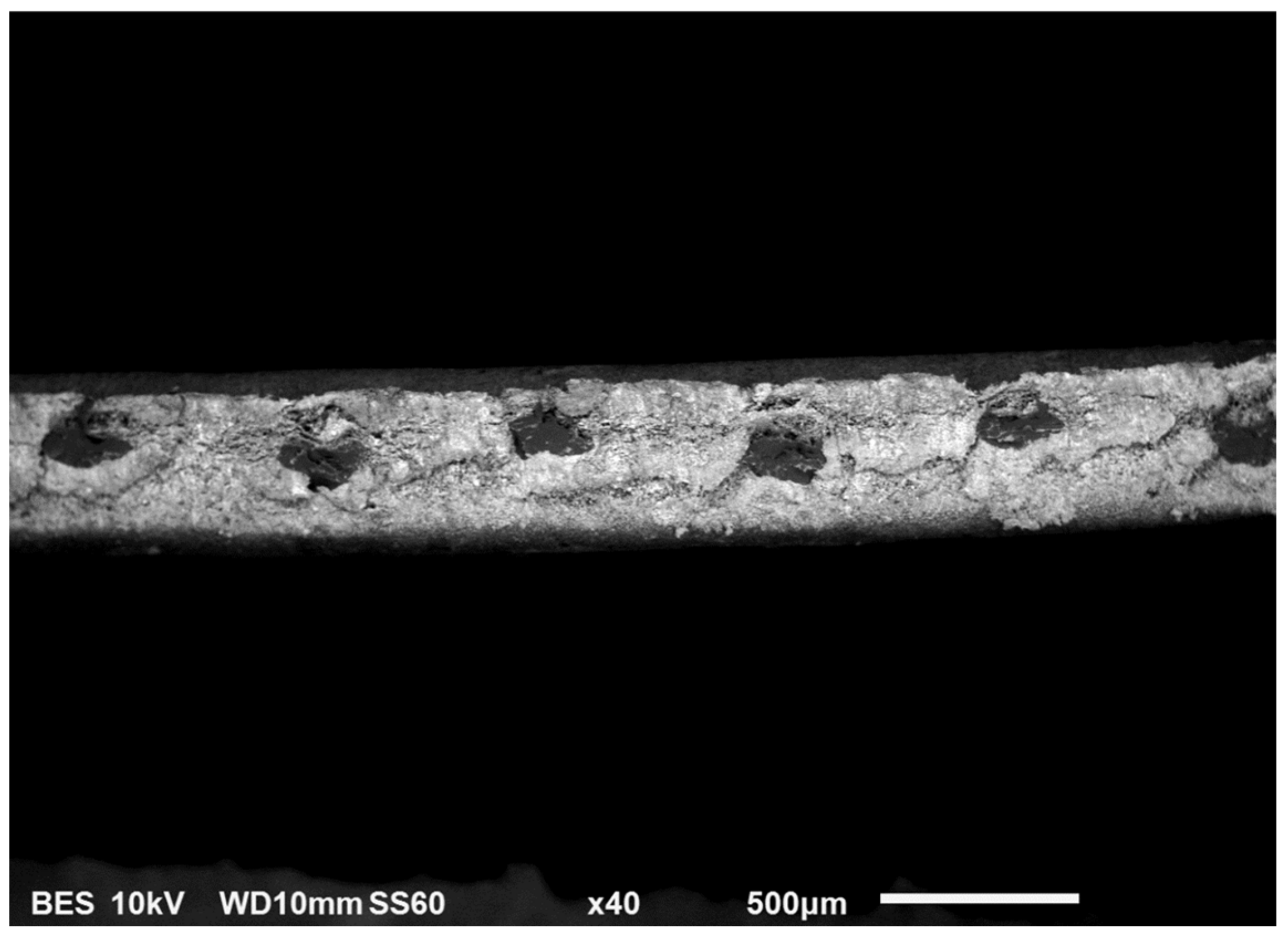
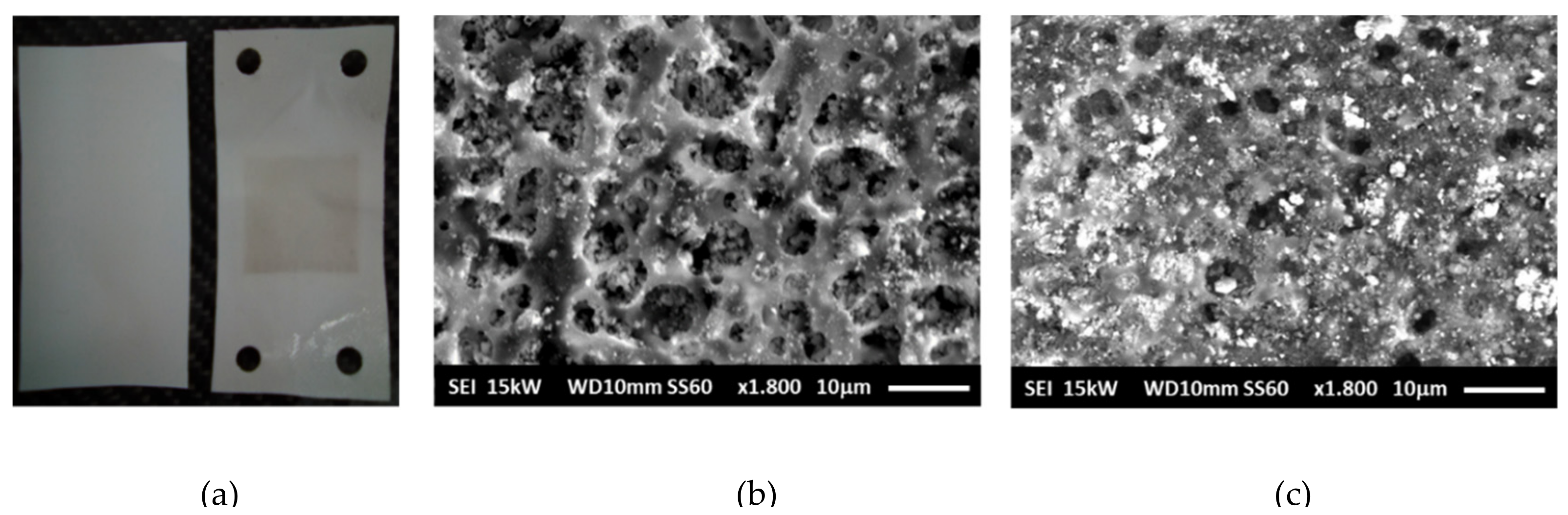
2, potential values of 1.88V, and 2.22 V were obtained for new samples. However, for aged samples, the potential achieved 1.93V, and 2.29 V, respectively. Although, the worsening of the electrochemical response could be caused by different processes, those occurring in the diaphragm play a significant role. The effect of ageing on the morphology of Zirfon
® diaphragms is shown in
Figure 8. After long-time operation, the Zirfon
® samples showed a dark deposition over the surface area exposed to electrolyte (
Figure 8). A brown-grey square, corresponding to the active area of the diaphragm (10 cm
2), can be clearly identified (
Figure 8a). SEM images for new and aged samples (
Figure 8b,c, respectively) confirmed the formation of some deposits over the aged sample surface, which could partially or totally obstruct the available pores: Significant reduction of number of big pores is easily identified by comparing both images.
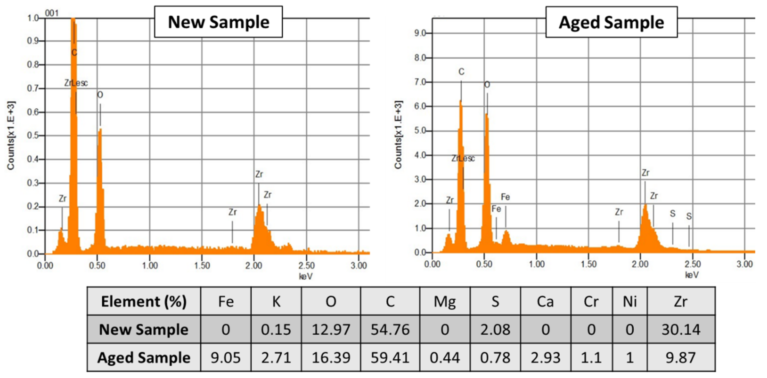
EDS Spectra (
Figure 9) demonstrated that the deposits mainly corresponded to iron compounds (with a percentage close to 9% of mass). The origin of these deposits could be the auxiliary equipment, such as tubing, adapters, pumps, liquid-gas separators, which under AWE operation conditions, could easily corrode. The covering of pores could result in a poorer charge transport, and then in an increase in ohmic resistance of the diaphragm.
3.1. Direct Current Method
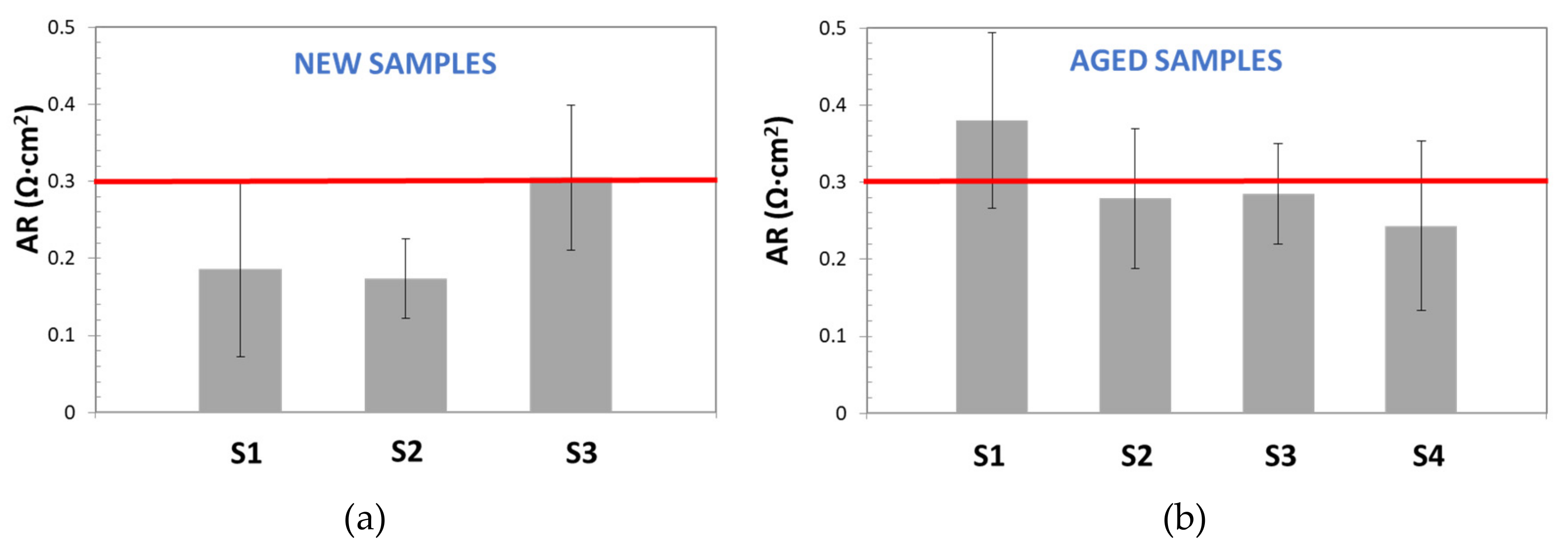
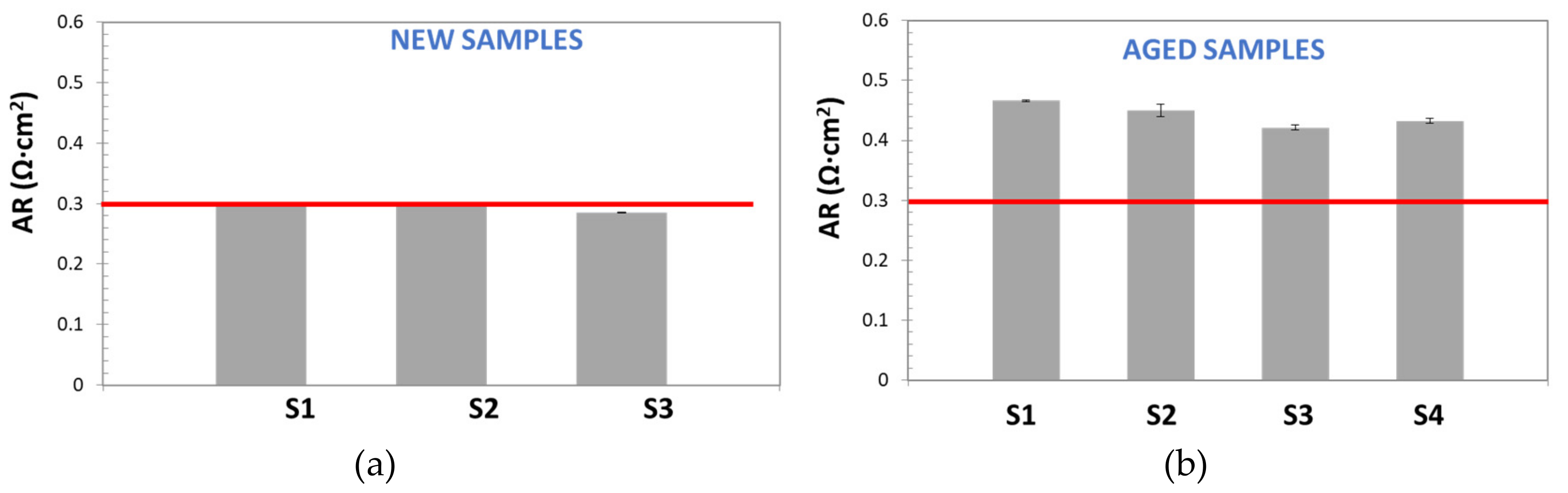
In
Figure 10, AR values, obtained by the DC method for new and aged samples, are reported and compared with the commercial reference value for Zirfon
® [
18] (red line): ≤0.3 Ω cm
2 (KOH 30 wt%, 30 °C).
This figure demonstrates the low repeatability and the poor accuracy of the DC Method. On one hand, for both, new and aged samples, most of calculated AR values were far from the reference one; on the other hand, wide standard deviation bars were obtained (sometimes higher than 20%), even for the sample with AR similar to the reference. Although, standard deviation variation seems too high, it is in good agreement with the results observed by other authors. For instance, Agel et al. [
13] obtained SD values in the range of 10–20%, for anionic membranes in KOH, at a concentration varying between 0.1 and 7.2 M.
3.2. EIS Method
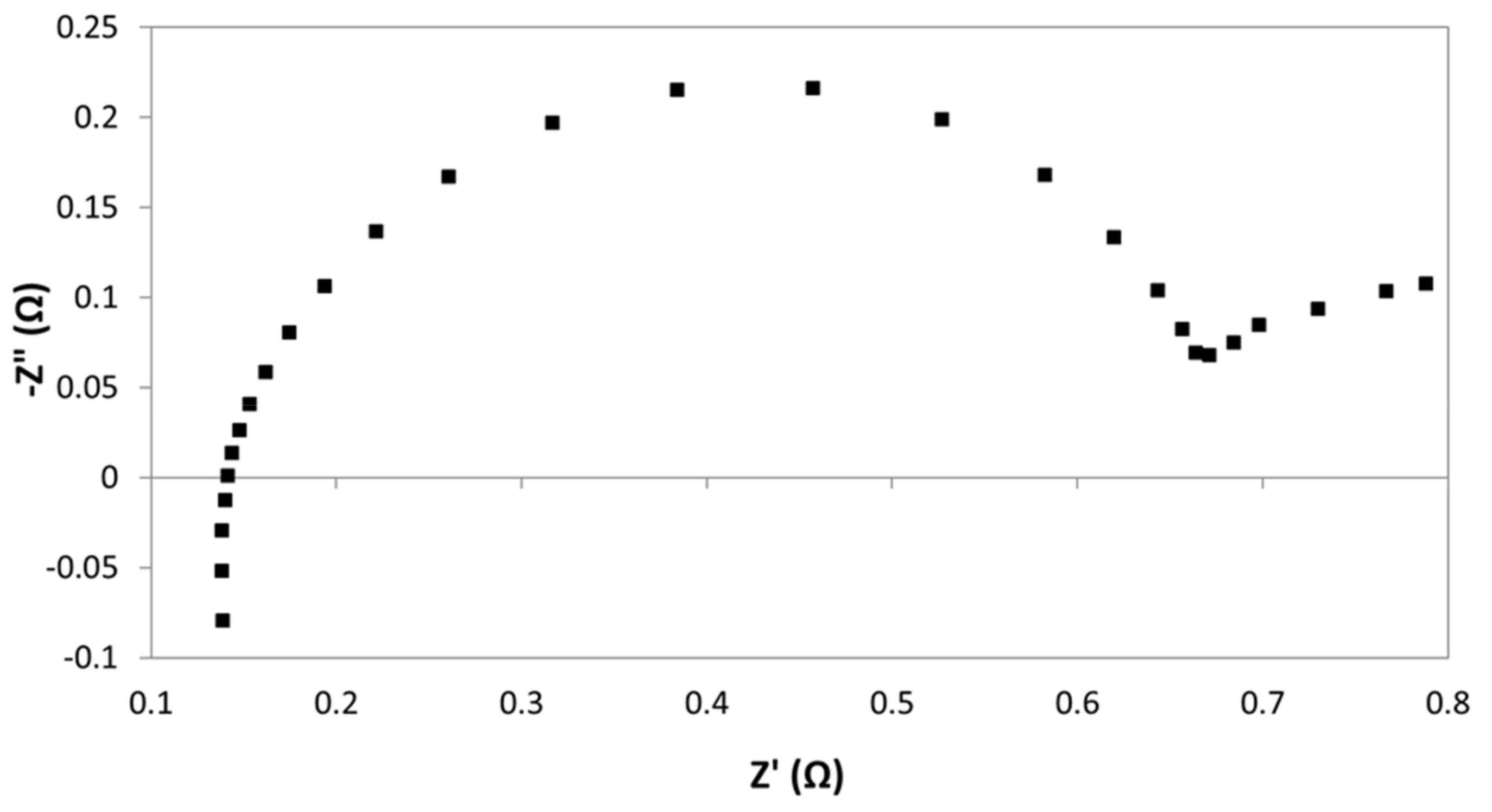
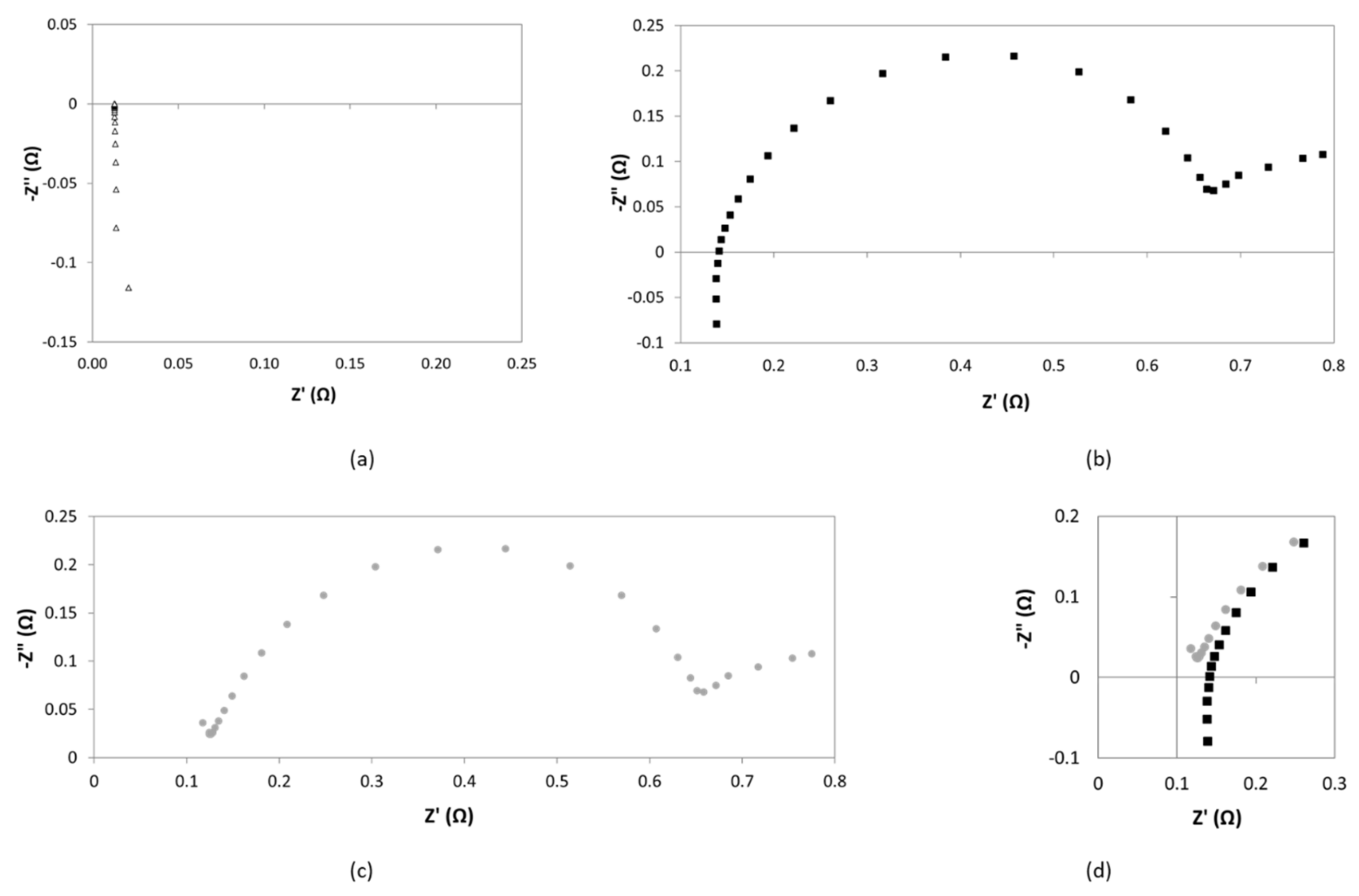
As we can observe from
Figure 11, parasitic phenomena were identified at high frequency in the fourth quadrant of the Nyquist, which were attributed to inductance effects caused by possible wires connections between potentiostat and electrochemical cell. According to the bibliography [
23,
24], while capacitance effects may dominate in the case of large systems with high impedance, inductance may dominate the errors in low impedance systems, such as in the present study [
24]. In fact, inductance is one of the most common interfering factors when measuring through-plane impedance [
22]: Configuration of the cell, but specially length and nature of electrical wires can strongly determine inductance effects [
24].
Notably, when working with very concentrated electrolytes, as in the present case, the difference between the resistance of diaphragm and electrolyte is very low, so that, even small perturbations caused by inductance can induce high errors. Thus, the correction of inductance contribution becomes of paramount importance.
As reported by other authors, this can be done by short circuit calibration procedures [
23,
24]. Firstly, impedance of the shorted cell is measured under the same conditions as those used for diaphragms measurements. Then, correction of the impedance is done at each frequency, under the assumption that the impedances of the diaphragm and the parasitic components are additive quantities.
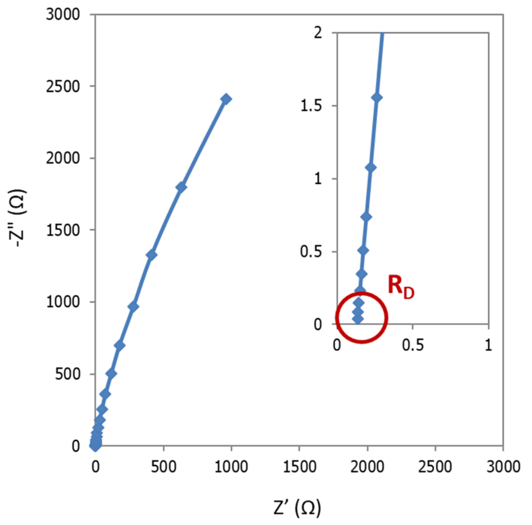
An example of the data obtained by this procedure is reported in
Figure 12. In
Figure 12a, it is shown the Nyquist diagram in short circuit conditions. It exhibits a common pipe shaped form, which indicates that the shift of inductance from the zero point determines the internal resistance of the cabling [
25,
26].
Figure 12b reports the EIS response at conditions as detailed
Section 2.4.2. In
Figure 12c it is presented the correction of experimental data following the current approach. Finally,
Figure 12d corresponds to the comparison between (b) and (c) at high frequencies zone. From this region, resistance of the cell can be obtained.
After correction, curve intersection with real axis shifts towards smaller values. This confirms that the correction allows a high accurate determination of separator resistance. However, as in this example, in most of the measurements, the resulting corrected diagram does not properly intercept the real axis. Thus, for accuracy purposes, the determination of the resistance of diaphragm was done by means of the equivalent circuit approach.
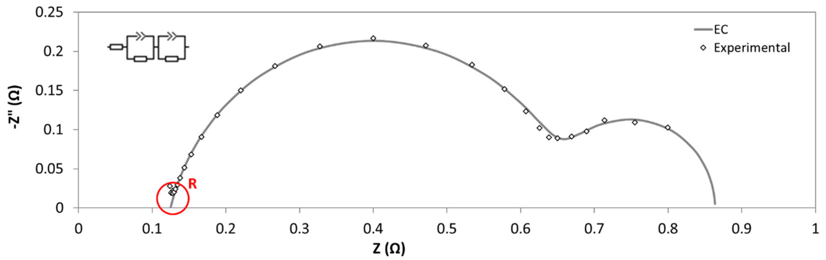
A typical Nyquist plot is shown in
Figure 13. Among with the EIS results, it is also presented the fitting data, calculated by using the equivalent circuit reported in the inset of this figure. In particular, the circuit consisted of two constant phase element (CPE)-Resistance parallel elements, and one series resistance. CPE instead of capacitance were needed to take into account for non-ideal behavior of capacitors [
27]. Each one of CPE-Resistance elements represents the electrochemical reaction at cathode, and anode, respectively. Series resistance corresponded to ohmic losses: Diaphragm, wires, electric contacts, electrolyte, etc. This resistance coincides with real impedance part at high frequencies.
From subsequent assays, with and without diaphragm and using Equations (1) and (8) the Area Resistance of diaphragm was obtained.
Once the EIS response was corrected, AR was determined for Zirfon
® diaphragms, as described in
Section 2.
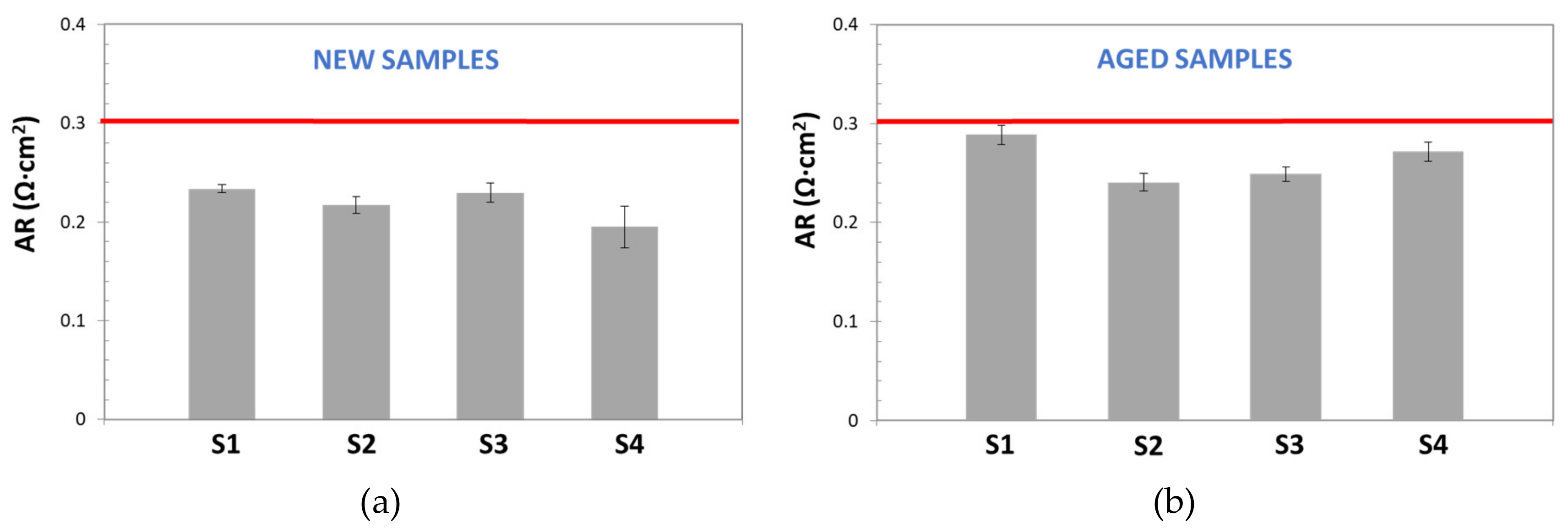
Figure 14 shows the results obtained for new and aged samples. It is possible to confirm that more stable area resistance values were obtained by this technique. The results also evidenced that EIS-based methods (Alternating Current) offered more precise and repeatable measurements than Direct Current techniques, and so it makes them more appropriate for electrochemical characterization of low resistance components. Furthermore, low standard deviation values were calculated for all studied samples. For new samples SD was in the range of 7.4–9.7 × 10
−4 Ω, while for aged samples it varied from to 4 × 10
−4 to 2 × 10
−2 Ω. These values represent a significant increment of precision respect the DC method.
However, the results for new and aged samples were always lower than area resistance values reported by the manufacturer (≥0.3 Ω·cm
2): 0.19–0.24 Ω·cm
2 and 0.24–0.29 Ω·cm
2, for new, and aged samples, respectively. As pointed above, this variation, could be related to errors, due to the subtraction of electrolyte resistance, especially relevant when working with highly conductive electrolytes and low resistive separator, as in this case. Additionally, the apparent similarity of corresponded ohmic resistance obtained for all samples, can be also explained, considering that ohmic resistance is contributed by several resistances: Electrode materials, electric contact, electrolyte, etc. [
28], and for EIS-method, the same electrodes and electrolyte conditions were used.
When compared with DC method, more stable and reproducible values of ohmic resistance (and thus area resistance (AR)) were obtained by this EIS technique, which may be considered more appropriate for electrochemical characterization of low resistance components.
3.3. Zero-Gap EIS
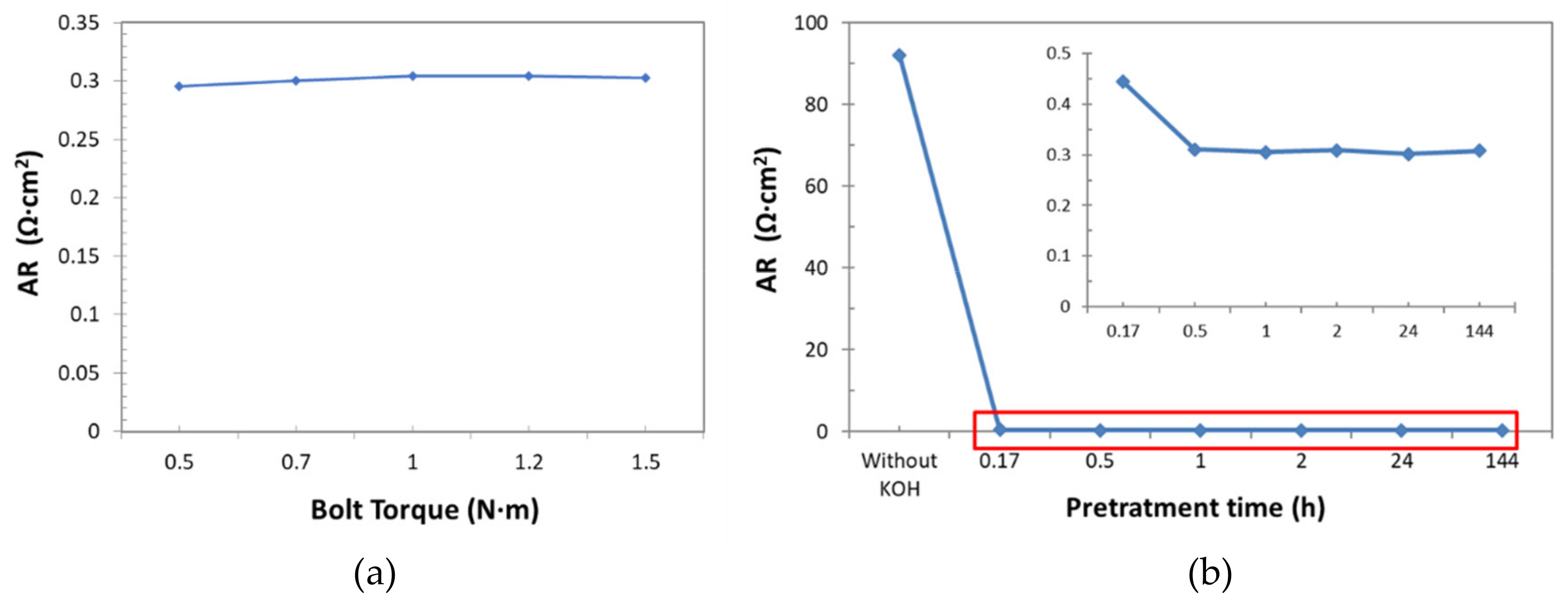
For this approach, the influence of the bolt torque of set-up cell, as well as of the pre-treatment of samples on the resistance measurements (
Figure 15a) were firstly analyzed.
To evaluate the right bolt torque to apply to the sample, a new sample of Zirfon
® was immerged in KOH (30 wt%) for 24 h, then introduced into the cell, for the AR determination (as described in
Section 2.3). The bolt torque values adopted, ranged from 0.5 to 1.5 N·m. Results reported in
Figure 14a indicated that there was not a significant effect on AR observed in this examined bolt torque range: Only a low increase in the resistance was observed from 0.5 up to 1 N·m, but then, AR values were practically the same. Value of 1 N·m was selected as nominal bolt torque.
To determine the suitable pre-treatment time, new samples were immerged in KOH (30 wt%) at ambient temperature for different times: 0h, 0.17 h, 0.5 h, 1 h, 2 h, 24 h, and 144 h.
Figure 15b shows that, unexpectedly, low pre-treatment times were enough to fill the diaphragm channels. In fact, after 30 minutes the AR values did not change significantly. So, in order to guarantee a complete filling of channels a pre-treatment time of 1 h was considered suitable for AR determination.
After fixing the previous operational aspects, the AR experiments were carried out (
Figure 16). Also, in this method, inductance correction was carried out, as previously described. The results demonstrated that this technique showed higher repeatability, precision, and accuracy than previous techniques, even than the EIS-based one. It is worth noting the low variation of standard deviation for both types of samples (aged and new ones).
Regarding the new samples, AR determination reported very close values to reference one. This is a confirmation of accuracy of proposed method. For aged samples, a reproducible response was also obtained. In addition, in this case, AR was higher (between 40% and 50% higher) than reference value for all analyzed samples. The increase in resistance of diaphragms after long operation times can be expected and it is in good agreement with the reduction of the cell performance with time operation, discussed above.
3.4. Comparison between Techniques
In
Table 2, the results of the analysis of all three studied techniques are shown. In particular, the values of resistance, standard deviation, coefficient variation, error, ionic conductivity, and tortuosity, are reported.
If the resistance is concerned, we must notice that its value is mostly determined by material and geometry. Being the same material for all cases, resistance values strongly depend on sample geometry, which is defined by system architecture. Therefore, in order to correctly compare the different techniques, a proportional resistance concept (as area resistance) could be more suitable, because it does not depend on geometry. However, since precision is analyzed in terms of standard deviation and coefficient variation, which depend on resistance, to a more complete analysis, in the present work, resistance average values are reported.
Taking this into account, from
Table 2 it is seen that DC technique is the least precise, because it reported a higher variability of resistance measurements, as confirmed by the high values of coefficient variation: 32% and 41.7%. These results suggest that experimental resistance measurements varied in a wide range, as shown in
Figure 10. The low precision of this technique was also observed by other authors [
13]. Despite this, DC technique is widely used for membrane resistance determination because its simplicity and low technique requirements. In fact, although in this work a potentiostat/galvanostat was used for electric measurements, this technique can be also undertaken by using a power source and a common voltmeter, as reported in the literature [
29].
In contrast, EIS techniques showed very low CV values, confirming that alternating the current techniques are more precise than DC techniques [
7]. Among them, EIS-Zero Gap technique reported values as low as 0.33%, demonstrating that it is the most repeatable method. The difference between both EIS techniques is related to the presence of an electrolyte volume between the electrodes and separator, which also has an ohmic contribution, thus increasing the error of the EIS-method.
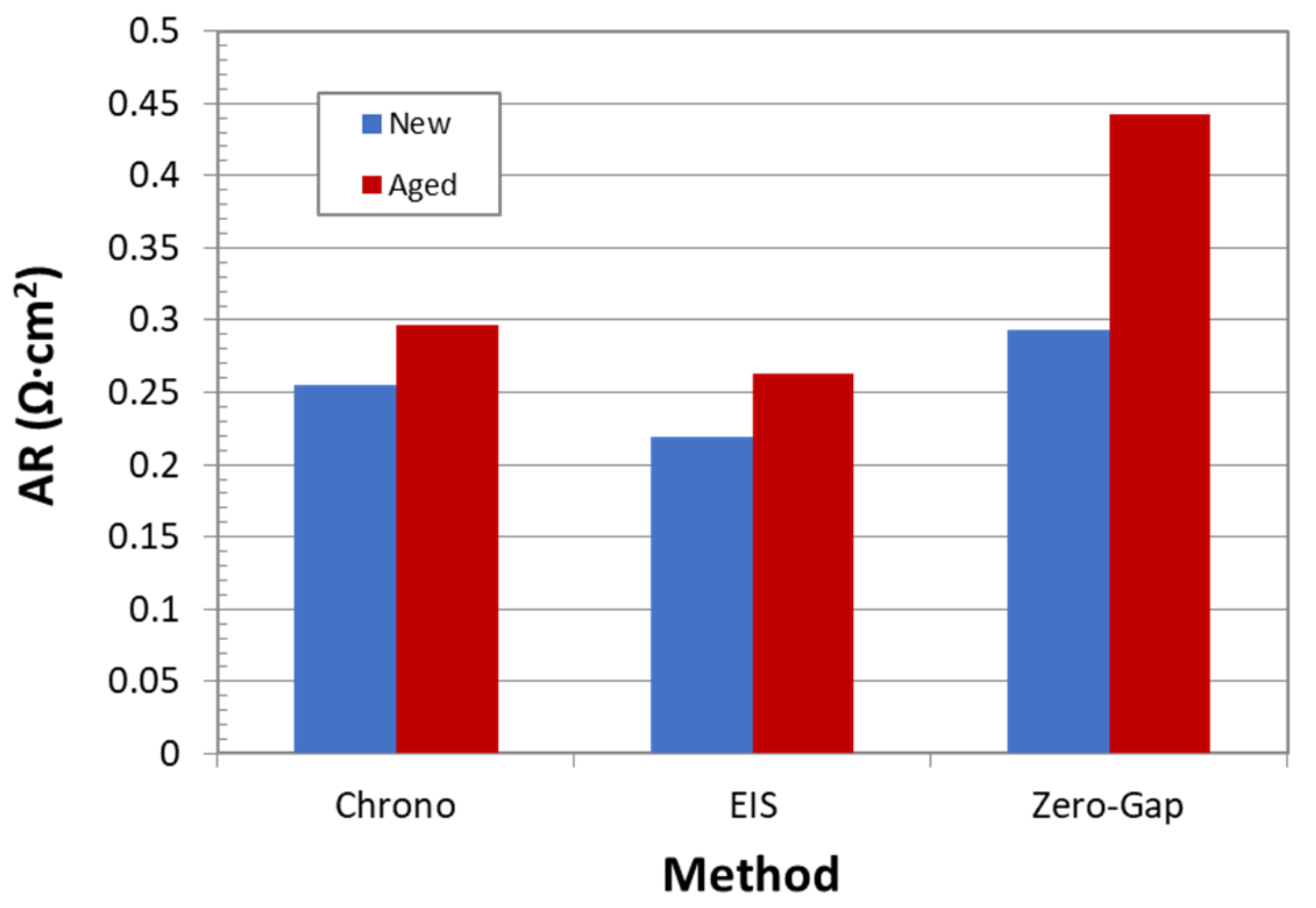
If accuracy data are considered, they were evaluated by contrasting experimental values of area resistance with the theoretical one, supplied by the manufacturer.
Figure 17 reports values of area resistance for new and aged samples for all three studied techniques. The comparison must be mainly done with respect to new samples, because it is very difficult to find comparable references for aged samples.
In this case, the best results also correspond to the Zero-Gap EIS method. In fact, the calculated area resistance value is practically equal to the reported one (0.3 Ω·cm). Unlike the expected behavior, DC technique showed a higher accuracy than EIS method. In the opinion of the authors, considering the high variability of DC methods, the result obtained by this technique are not reliable. Nevertheless, even if the EIS method is an accurate technique, the obtained result is far from the reference one. This poor performance can probably be related to ohmic contribution of electrolyte and subtraction calculations. This can be also confirmed by the fact that even aged samples resistance, determined by this technique, is much lower than the reference value for new separators.
Furthermore, although no aged samples references were found, the convenience of the EIS-Zero Gap method for aged samples can be evaluated in terms of ohmic contribution with respect to the total ohmic overpotential of the cell. According to the literature, the ohmic over-potential can represent up to 20% of the overall voltage in an alkaline electrolysis cell when the current density is 400 mA/cm
2, being the energy loss due to bubble formation on the electrodes the major contribution to the total over-potentials (more than 50%), and the separator about 15% [
5,
30]. So, the diaphragm contributes up to 3% of the overall cell potential at high current densities. As shown in
Figure 17, an increase in the AR of 50% is observed in the aged diaphragm, so the contribution of the separator in the ohmic overpotential could increase up to 4–5%. On the other hand, according to
Figure 8, an increase in potential of approximately 4% occurs after 130 h of operation, so it seems that there is a direct relationship between the increase in the cell potential and the resistance measured with the EIS zero-gap technique.
Finally, besides precision and accuracy, in
Table 2 conductivity and tortuosity are also reported. Ionic conductivity corresponds to conductivity of electrolyte inside the separator channels. On the other hand, tortuosity gives information about irregularity and sinuosity of channels inside the separator. The values in the range of 1.5–1.9 were obtained in this study for new samples. The ionic conductivity and tortuosity agree with the data reported in literature [
11,
31]. Thus, it can be concluded that a precise approach to determining the resistance contribution of diaphragms can be also useful for a more complete material characterization, including geometrical and physical-chemical parameters. Then, the choice of a suitable approach becomes critical. Among the analyzed methodologies in this study, the proposed Zero Gap-EIS method was revealed to be the most convenient one in terms of simplicity, accuracy, and precision.
4. Conclusions
A simple and repeatable methodology, based on Electrochemical Impedance Spectroscopy, was presented in this work, and its application to diaphragm characterization was studied. Furthermore, the application of this method was compared with two, well-known methodologies, commonly used in the literature: DC-based technique and an EIS-based one. For comparison purposes, a commercial diaphragm normally used in AWE, Zirfon®, was selected as reference material.
DC-based methodology showed low repeatability, and poor accuracy and precision for standard deviation values, which varied in the range of 30–40%. Experimental deviation agreed with the observations by other authors. Although it is a simple technique, due to the poor results, it is not considered a suitable solution for determining the diaphragm resistivity in AWE.
On the other hand, the EIS-based technique reported good accuracy, but a lower precision than expected. Standard Deviation values close to 4–5% were calculated, confirming the good repeatability of this technique. Nevertheless, the area resistance, obtained by this approach, was the lowest, far away from the reference value of the commercial material. The cause of this strong difference can be found in the contribution to the ohmic resistance of the electrolyte filling the anodic and cathodic compartment. Being the resistance of diaphragm at a low value, the subtraction of the resistance of a substantial electrolyte volume can increase the error due to the calculations. These results suggested that, despite the convenience of using alternating current measurements instead of direct current ones, a not-subtracting approach can be preferred for high porosity diaphragms, in strong concentrated media, in order to reduce errors from calculations.
In relation to the Zero Gap-EIS Method proposed in this work, the most accurate and precise results were obtained by this approach. The good performance of this methodology was due to two aspects: Use of EIS technique favored a repeatable experimental response; and the elimination of the correction with the electrolyte resistance, which reduced the total error. As consequence, very low standard deviation values (in the range of 1%) were obtained, and the area resistance calculated for Zirfon® was almost the same than reported by the manufacturer.
In addition, in order to ascertain the influence of operation time over the performance of the diaphragm, the aged diaphragm samples were also studied. For all methods, a higher resistance was calculated for aged samples with respect to the new ones. The increasing resistance was related to the deposition of metal compounds on the surface of diaphragm, which could block the channels, and limit the OH− ions transport.
Finally, it was confirmed that, by using the described methodologies, other physical-chemical properties (tortuosity and ionic conductivity) of diaphragms can be determined, allowing a more complete characterization of these components. Accordingly, choosing a suitable approach for diaphragm resistance determination becomes critical.
In the present study, the proposed Zero Gap-EIS methodology showed to be the optimal option. Authors expect that this simple and economical approach could contribute to propel the future research on new membranes and diaphragms materials for Alkaline Water Electrolysis.

 ,
, 


