Performance of Void-Free Electrospun SPEEK/Cloisite as a Function of Degree of Dispersion State on Nanocomposite Proton Exchange Membrane for Direct Methanol Fuel Cell Application
Abstract
1. Introduction
2. Experimental
2.1. Materials
2.2. Synthesis of Sulfonated Poly(Ether Ether Ketone) (SPEEK)
2.3. Preparation of Electrospinning Dope Solution
2.4. Electrospinning of Nanofibers
2.5. Preparation of Void-Free SP/e-spun Cloisite Membrane
2.6. Characterization
2.6.1. Atomic Force Microscope (AFM)
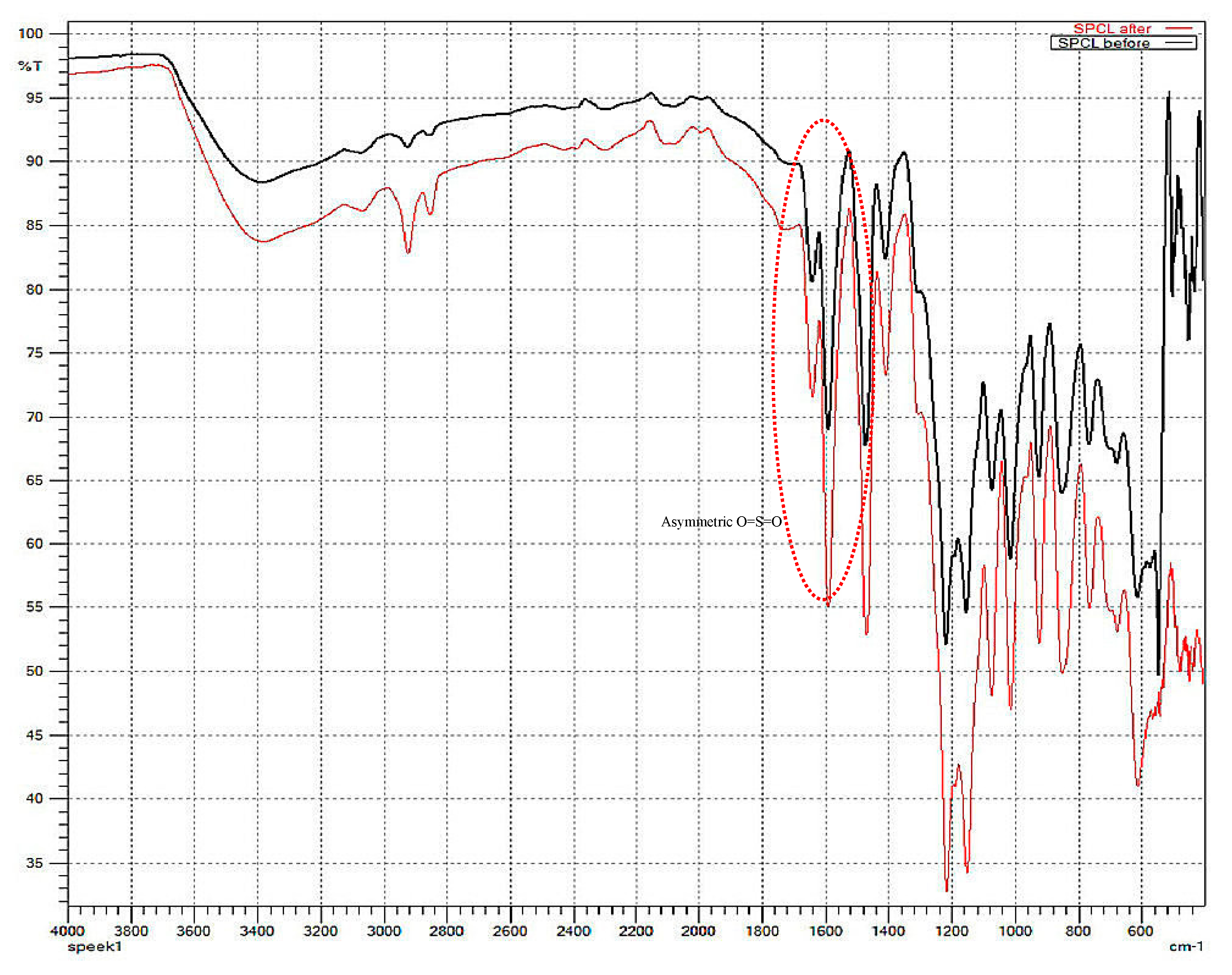
2.6.2. Fourier Transform Infrared Spectroscopy
2.6.3. Scanning Electron Microscopy Analysis (SEM)
2.6.4. Field Emission Scanning Electron Microscopy (FESEM)
2.6.5. X-ray Diffraction Analysis
2.6.6. Dimensional Stability
2.6.7. Dissolution Test and Water Uptake
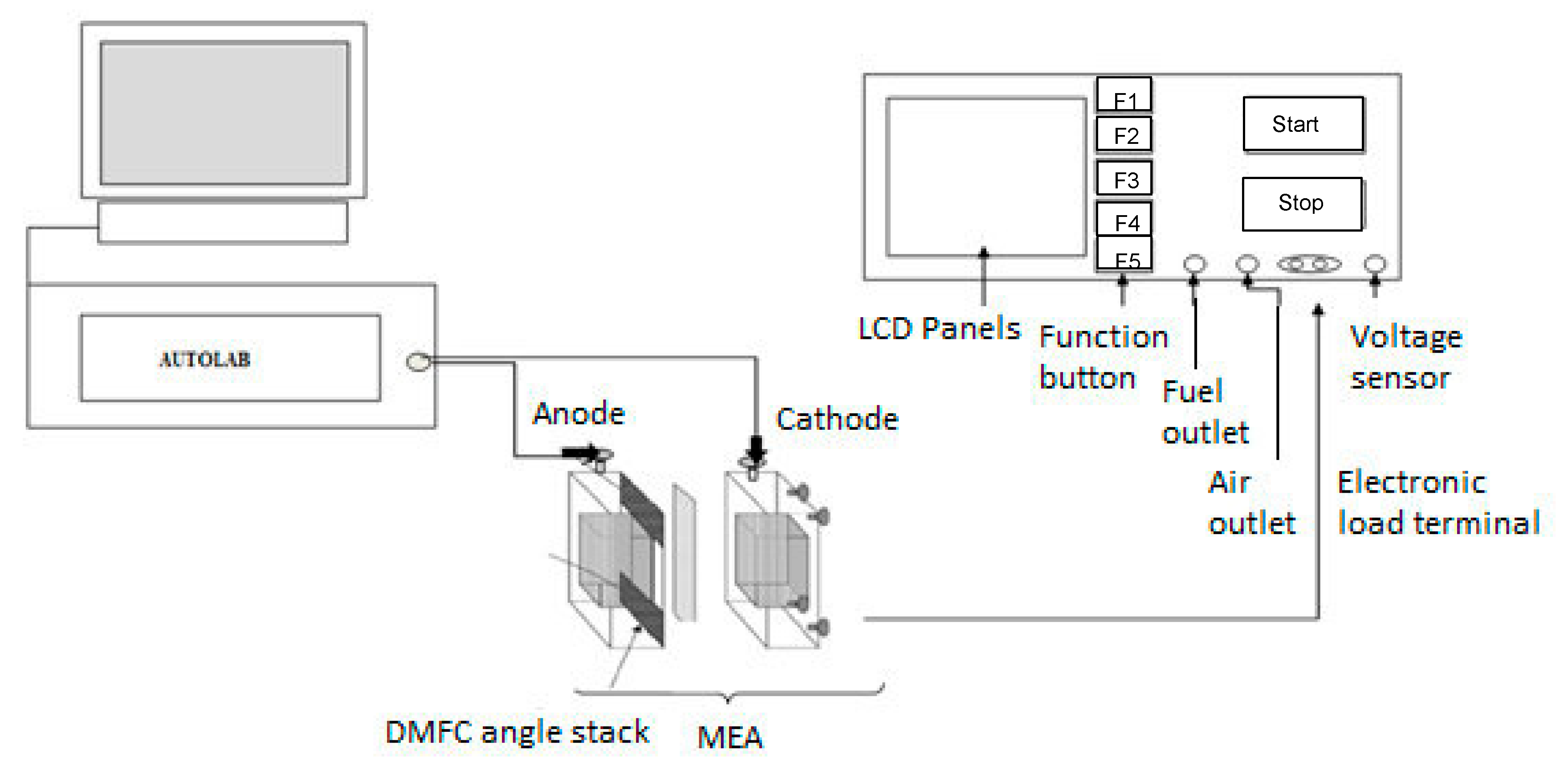
2.7. Single PEM Direct Methanol Fuel Cell Test
2.7.1. Preparation of Membrane Electrode Assembly (MEA)
2.7.2. Single DMFC Performance Testing
3. Results and Discussion
3.1. Structural Characterization of SP/e-spunCL Membranes
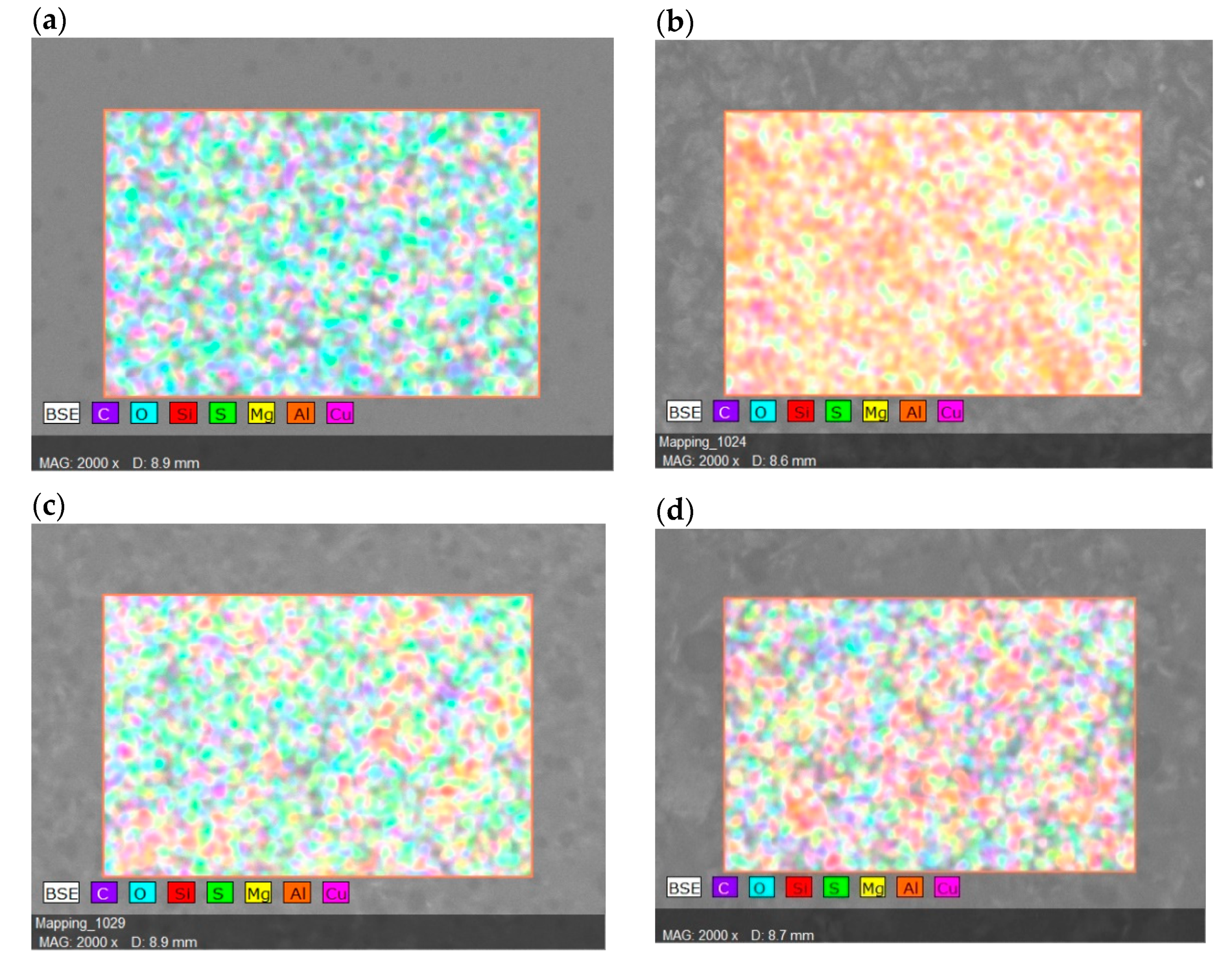
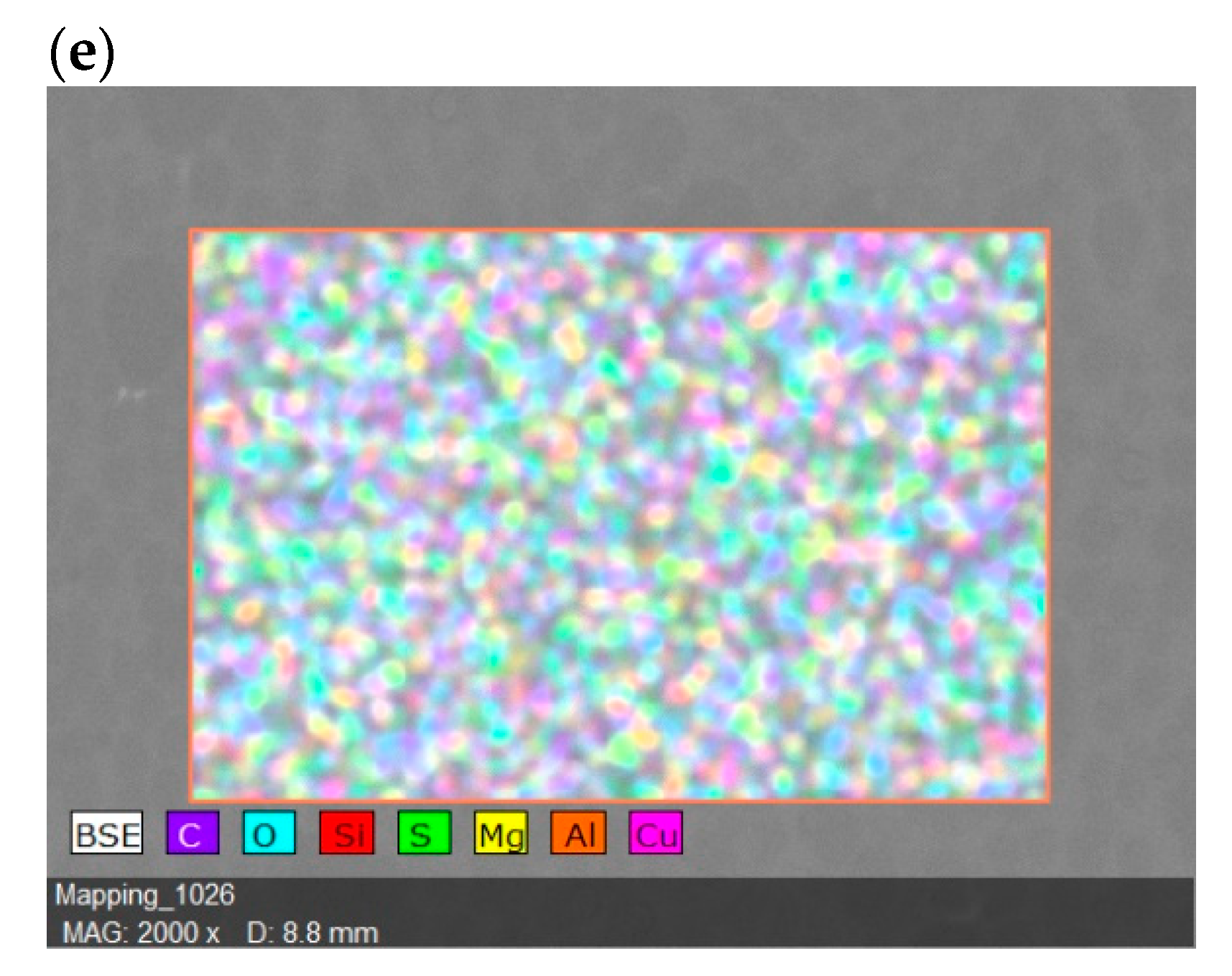
3.2. The Effects of Morphological Structures and Closite Dispersion on Barrier Property of Void-Free SP/e-spunCL
3.3. Dimensional Stability of SP/e-spunCL Membranes
3.4. Long Term Stability of SP/e-spunCL Membranes in Hydrated State
3.5. DMFC Performance
4. Conclusions
Author Contributions
Funding
Acknowledgments
Conflicts of Interest
References
- Awang, N.; Jaafar, J.; Ismail, A.F. Thermal Stability and Water Content Study of Void-Free Electrospun SPEEK/Cloisite Membrane for Direct Methanol Fuel Cell Application. Polymers 2018, 10, 194. [Google Scholar] [CrossRef]
- Junoh, H.; Jaafar, J.; Nor, N.A.M.; Awang, N.; Norddin, M.N.A.M.; Ismail, A.F.; Salleh, W.N.W. Fabrication of Nanocomposite Membrane via Combined Electrospinning and Casting Technique for Direct Methanol Fuel Cell. J. Membr. Sci. Res. 2017, 4, 146–157. [Google Scholar]
- Meinel, A.J.; Kubow, K.E.; Klotzsch, E.; Garcia-Fuentes, M.; Smith, M.L.; Vogel, V.; Merkle, H.P.; Meinel, L. Optimization strategies for electrospun silk fibroin tissue engineering scaffolds. Biomaterials 2009, 30, 3058–3067. [Google Scholar] [CrossRef] [PubMed]
- Awang, N.; Jaafar, J.; Ismail, A.F.; Othman, M.H.D.; Rahman, M.A. Effects of SPEEK/Cloisite Concentration as Electrospinning Parameter on Proton Exchange Membrane for Direct Methanol Fuel Cell Application. Mater. Sci. Forum 2017, 890, 278–284. [Google Scholar] [CrossRef]
- Chakrabarty, T.; Kumar, M.; Rajesh, K.P.; Shahi, V.K.; Natarajan, T.S. Nano-fibrous sulfonated poly(ether ether ketone) membrane for selective electro-transport of ions. Sep. Purif. Technol. 2010, 75, 174–182. [Google Scholar] [CrossRef]
- Awang, N.; Ismail, A.F.; Jaafar, J.; Matsuura, T.; Junoh, H.; Othman, M.H.D.; Rahman, M.A. Functionalization of polymeric materials as a high performance membrane for direct methanol fuel cell: A review. React. Funct. Polym. 2015, 86, 248–258. [Google Scholar] [CrossRef]
- Jaafar, J.; Ismail, A.F.; Othman, M.H.D.; A Rahman, M.; Aziz, F. Fabrication Of Nanocomposite Membrane Via Combined Electrospinning And Casting Technique For Direct Methanol Fuel Cell. J. Membr. Sci. Res. 2018, 4, 146–157. [Google Scholar]
- Liu, D.; Geng, L.; Fu, Y.; Dai, X.; Lü, C. Novel nanocomposite membranes based on sulfonated mesoporous silica nanoparticles modified sulfonated polyimides for direct methanol fuel cells. J. Membr. Sci. 2011, 366, 251–257. [Google Scholar] [CrossRef]
- Awang, N.; Jaafar, J.; Ismail, A.F.; Othman, M.H.D.; Rahman, M.A.; Yusof, N.; Azman, W.W.M.N. Development of dense void-free electrospun SPEEK-Cloisite15A membrane for direct methanol fuel cell application: Optimization using response surface methodology. Int. J. Hydrog. Energy 2017, 42, 26496–26510. [Google Scholar] [CrossRef]
- Lue, S.J.; Pai, Y.-L.; Shih, C.-M.; Wu, M.-C.; Lai, S.-M. Novel bilayer well-aligned Nafion/graphene oxide composite membranes prepared using spin coating method for direct liquid fuel cells. J. Membr. Sci. 2015, 493, 212–223. [Google Scholar] [CrossRef]
- Hassan, S.H.; El-Rab, S.M.G.; Rahimnejad, M.; Ghasemi, M.; Joo, J.H.; Sik-Ok, Y.; Kim, I.S.; Oh, S.E. Electricity generation from rice straw using a microbial fuel cell. Int. J. Hydrogen Energy 2014, 39, 9490–9496. [Google Scholar] [CrossRef]
- Alexandre, M.; Dubois, P. Polymer-layered silicate nanocomposites: Preparation, properties and uses of a new class of materials. Mater. Sci. Eng. R Rep. 2000, 28, 1–63. [Google Scholar] [CrossRef]
- Awang, N.; Jaafar, J.; Ismail, A.F.; Matsuura, T.; Othman, M.H.D.; Rahman, M.A. Electrospun Nanocomposite Materials for Polymer Electrolyte Membrane Methanol Fuel Cells. In Organic-Inorganic Composite Polymer Electrolyte Membranes; Springer: Cham, Switzerland, 2017; pp. 165–191. [Google Scholar]
- Lertwimolnun, W.; Vergnes, B. Influence of compatibilizer and processing conditions on the dispersion of nanoclay in a polypropylene matrix. Polymer 2005, 46, 3462–3471. [Google Scholar] [CrossRef]
- Wang, H.; Tang, C.; Zhuang, X.; Cheng, B.; Wang, W.; Kang, W.; Li, H. Novel structure design of composite proton exchange membranes with continuous and through-membrane proton-conducting channels. J. Power Sources 2017, 365, 92–97. [Google Scholar] [CrossRef]
- Tijing, L.D.; Choi, J.-S.; Lee, S.; Kim, S.-H.; Shon, H.K. Recent progress of membrane distillation using electrospun nanofibrous membrane. J. Membr. Sci. 2014, 453, 435–462. [Google Scholar] [CrossRef]
- Pai, Y.-H.; Ke, J.-H.; Chou, C.-C.; Lin, J.-J.; Zen, J.-M.; Shieu, F.-S. Clay as a dispersion agent in anode catalyst layer for PEMFC. J. Power Sources 2006, 163, 398–402. [Google Scholar] [CrossRef]
- Bhardwaj, N.; Kundu, S.C. Electrospinning: A fascinating fiber fabrication technique. Biotechnol. Adv. 2010, 28, 325–347. [Google Scholar] [CrossRef] [PubMed]
- Hashemifard, S.A.; Ismail, A.F.; Matsuura, T. Effects of montmorillonite nano-clay fillers on PEI mixed matrix membrane for CO2 removal. Chem. Eng. J. 2011, 170, 316–325. [Google Scholar] [CrossRef]
- Jeeva Jothi, K.; Palanivelu, K. Synergistic effect of silane modified nanocomposites for active corrosion protection. Ceram. Int. 2013, 39, 7619–7625. [Google Scholar] [CrossRef]
- Rezaei, M.; Ismail, A.F.; Bakeri, G.; Hashemifard, S.A.; Matsuura, T. Effect of general montmorillonite and Cloisite 15A on structural parameters and performance of mixed matrix membranes contactor for CO2 absorption. Chem. Eng. J. 2015, 260, 875–885. [Google Scholar] [CrossRef]
- Paul, D.R.; Robeson, L.M. Polymer nanotechnology: Nanocomposites. Polymer 2008, 49, 3187–3204. [Google Scholar] [CrossRef]
- Pupkevich, V.; Glibin, V.; Karamanev, D. Phosphorylated polyvinyl alcohol membranes for redox Fe3+/H2 flow cells. J. Power Sources 2013, 228, 300–307. [Google Scholar] [CrossRef]
- Kim, D.S.; Park, H.B.; Rhim, J.W.; Moo Lee, Y. Preparation and characterization of crosslinked PVA/SiO2 hybrid membranes containing sulfonic acid groups for direct methanol fuel cell applications. J. Membr. Sci. 2004, 240, 37–48. [Google Scholar] [CrossRef]
- Peponi, L.; Puglia, D.; Torre, L.; Valentini, L.; Kenny, J.M. Processing of nanostructured polymers and advanced polymeric based nanocomposites. Mater. Sci. Eng. R Rep. 2014, 85, 1–46. [Google Scholar] [CrossRef]
- Sengwa, R.J.; Choudhary, S.; Sankhla, S. Dielectric spectroscopy of hydrophilic polymers—Montmorillonite clay nanocomposite aqueous colloidal suspension. Colloids Surf. A Physicochem. Eng. Asp. 2009, 336, 79–87. [Google Scholar] [CrossRef]
- Cui, Y.; Kundalwal, S.I.; Kumar, S. Gas barrier performance of graphene/polymer nanocomposites. Carbon 2016, 98, 313–333. [Google Scholar] [CrossRef]
- Etmimi, H.M.; Mallon, P.E.; Sanderson, R.D. Polymer/graphite nanocomposites: Effect of reducing the functional groups of graphite oxide on water barrier properties. Eur. Polym. J. 2013, 49, 3460–3470. [Google Scholar] [CrossRef]
- Sadiku, E.R.; Babul Reddy, A.; Gnanasekarana, D.; Oboirien, B.; Aderibigbe, B.A.; Varaprasad, K.; Goddeti, S.M.R. Design and Applications of Nanostructured Polymer Blends and Nanocomposite Systems. In Design and Applications of Nanostructured Polymer Blends and Nanocomposite Systems; Elsevier: Amsterdam, the Netherlands, 2016; pp. 239–259. [Google Scholar]
- Sinha Ray, S. Environmentally Friendly Polymer Nanocomposites. In Environmentally Friendly Polymer Nanocomposites; Elsevier: Amsterdam, The Netherlands, 2013; pp. 328–345. [Google Scholar]
- Silva, V.S.; Ruffmann, B.; Vetter, S.; Boaventura, M.; Mendes, A.M.; Madeira, L.M.; Nunes, S.P. Mass transport of direct methanol fuel cell species in sulfonated poly(ether ether ketone) membranes. Electrochim. Acta 2006, 51, 3699–3706. [Google Scholar] [CrossRef]
- Boaretti, C.; Pasquini, L.; Sood, R.; Giancola, S.; Donnadio, A.; Roso, M.; Modesti, M.; Cavaliere, S. Mechanically stable nanofibrous sPEEK/Aquivion® composite membranes for fuel cell applications. J. Membr. Sci. 2018, 545, 66–74. [Google Scholar] [CrossRef]
- Likhitha, M.; Sailaja, R.R.N.; Priyambika, V.S.; Ravibabu, M.V. Microwave assisted synthesis of guar gum grafted sodium acrylate/cloisite superabsorbent nanocomposites: Reaction parameters and swelling characteristics. Int. J. Boil. Macromol. 2014, 65, 500–508. [Google Scholar] [CrossRef]
- Ardakani, A.; Yazdani, M. The relation between particle density and static elastic moduli of lightweight expanded clay aggregates. Appl. Clay Sci. 2014, 93–94, 28–34. [Google Scholar] [CrossRef]
- Oh, Y.; Kim, S.-K.; Peck, D.-H.; Jung, D.-H.; Shul, Y. Effects of membranes thickness on performance of DMFCs under freeze-thaw cycles. Int. J. Hydrog. Energy 2014, 39, 15760–15765. [Google Scholar] [CrossRef]
- Krishnan, N.N.; Henkensmeier, D.; Park, Y.-H.; Jang, J.-H.; Kwon, T.; Koo, C.M.; Kim, H.-J.; Han, J.; Nam, S.-W. Blue membranes: Sulfonated copper(II) phthalocyanine tetrasulfonic acid based composite membranes for DMFC and low relative humidity PEMFC. J. Membr. Sci. 2016, 502, 1–10. [Google Scholar] [CrossRef]
- Kang, N.R.; Lee, S.Y.; Shin, D.W.; Hwang, D.S.; Lee, K.H.; Cho, D.H.; Kim, J.H.; Lee, Y.M. Effect of end-group cross-linking on transport properties of sulfonated poly(phenylene sulfide nitrile)s for proton exchange membranes. J. Power Sources 2016, 307, 834–843. [Google Scholar] [CrossRef]
- Lloyd, D. Synthesis Membranes and Membrane Separation Processes Takeshi Matsuura; CRC Press: Boca Raton, FL, USA, 1993; 467p, ISBN 08493-42023. [Google Scholar]
- Selamet, O.F.; Ergoktas, M.S. Effects of bolt torque and contact resistance on the performance of the polymer electrolyte membrane electrolyzers. J. Power Sources 2015, 281, 103–113. [Google Scholar] [CrossRef]
- Ilbeygi, H.; Ismail, A.F.; Mayahi, A.; Nasef, M.M.; Jaafar, J.; Jalalvandi, E. Transport properties and direct methanol fuel cell performance of sulfonated poly (ether ether ketone)/Cloisite/triaminopyrimidine nanocomposite polymer electrolyte membrane at moderate temperature. Sep. Purif. Technol. 2013, 118, 567–575. [Google Scholar] [CrossRef]
- Jaafar, J.; Ismail, A.F.; Matsuura, T.; Nagai, K. Performance of SPEEK based polymer–nanoclay inorganic membrane for DMFC. J. Membr. Sci. 2011, 382, 202–211. [Google Scholar] [CrossRef]
- Nguyen, T.H.; Wang, X. Fabrication of the porous polyimide film as a matrix of the composite membrane of the direct methanol fuel cell. Sep. Purif. Technol. 2009, 67, 208–212. [Google Scholar] [CrossRef]
- Shrivastava, N.K.; Thombre, S.B.; Mallick, R.K. Effect of diffusion layer compression on passive DMFC performance. Electrochim. Acta 2014, 149, 167–175. [Google Scholar] [CrossRef]
- Elabd, Y.A.; Walker, C.W.; Beyer, F.L. Triblock copolymer ionomer membranes. J. Membr. Sci. 2004, 231, 181–188. [Google Scholar] [CrossRef]
- Liang, H.; Su, H.; Pollet, B.G.; Pasupathi, S. Development of membrane electrode assembly for high temperature proton exchange membrane fuel cell by catalyst coating membrane method. J. Power Sources 2015, 288, 121–127. [Google Scholar] [CrossRef]
- Ilbeygi, H.; Mayahi, A.; Ismail, A.F.; Nasef, M.M.; Jaafar, J.; Ghasemi, M.; Matsuura, T.; Zaidi, S.M.J. Transport properties of SPEEK nanocomposite proton conducting membranes: Optimization of additives content by response surface methodology. J. Taiwan Inst. Chem. Eng. 2014, 45, 2265–2279. [Google Scholar] [CrossRef]
- Ahmadian-Alam, L.; Kheirmand, M.; Mahdavi, H. Preparation, characterization and properties of PVDF-g-PAMPS/PMMA-co-PAMPS/silica nanoparticle as a new proton exchange nanocomposite membrane. Chem. Eng. J. 2016, 284, 1035–1048. [Google Scholar] [CrossRef]
- Gang, M.; He, G.; Li, Z.; Cao, K.; Li, Z.; Yin, Y.; Wu, H.; Jiang, Z. Graphitic carbon nitride nanosheets/sulfonated poly(ether ether ketone) nanocomposite membrane for direct methanol fuel cell application. J. Membr. Sci. 2016, 507, 1–11. [Google Scholar] [CrossRef]
- Rambabu, G.; Bhat, S.D. Sulfonated fullerene in SPEEK matrix and its impact on the membrane electrolyte properties in direct methanol fuel cells. Electrochim. Acta 2015, 176, 657–669. [Google Scholar] [CrossRef]
- Carbone, A.; Saccà, A.; Pedicini, R.; Gatto, I.; Passalacqua, E.; Romeo, A.; Scolaro, L.M.; Castriciano, M.A. Composite sPEEK-TPyP membranes development for portable applications. Int. J. Hydrog. Energy 2015, 40, 17394–17401. [Google Scholar] [CrossRef]
- Zhang, S.; He, G.; Gong, X.; Zhu, X.; Wu, X.; Sun, X.; Zhao, X.; Li, H. Electrospun nanofiber enhanced sulfonated poly (phthalazinone ether sulfone ketone) composite proton exchange membranes. J. Membr. Sci. 2015, 493, 58–65. [Google Scholar] [CrossRef]



| Samples | Voltage (kV) | Distance (cm) | Designation |
|---|---|---|---|
| 0.10 wt.% electrospun SPEEK/Cloisite membrane | 22.5 | 20 | SP/e-spunCL10 |
| 0.15 wt.% electrospun SPEEK/Cloisite membrane | 22.5 | 20 | SP/e-spunCL15 |
| 0.20 wt.% electrospun SPEEK/Cloisite membrane | 22.5 | 20 | SP/e-spunCL20 |
| 0.25 wt.% electrospun SPEEK/Cloisite membrane | 22.5 | 20 | SP/e-spunCL25 |
| 0.30 wt.% electrospun SPEEK/Cloisite membrane | 22.5 | 20 | SP/e-spunCL30 |
| Transmission Bands (cm−1) | Functional Groups |
|---|---|
| 3400 | O–H from sulfonic group |
| 1640 | C=O |
| 1600 | Aromatic C=C |
| 1500 | Aromatic C–C |
| 1420 | 1,3,4-trisubstitured aromatic C–C skeletal vibrations |
| 1210–1170 | Asymmetric O=S=O stretching |
| 1000 | Symmetric O=S=O stretching |
| 700 | S–O stretch |
| Surface Elements | Surface Elements (wt.%) | ||||
|---|---|---|---|---|---|
| SP/e-spunCLs10 | SP/e-spunCL15 | SP/e-spunCL20 | SP/e-spunCL25 | SP/e-spunCL30 | |
| C | 40.94 | 41.19 | 41.01 | 41.42 | 42.88 |
| O | 21.69 | 21.94 | 21.76 | 22.76 | 24.63 |
| Si | 11.29 | 13.89 | 11.36 | 13.36 | 11.23 |
| S | 24.81 | 19.30 | 24.53 | 19.12 | 20.05 |
| Mg | 0.00 | 0.09 | 0.00 | 0.00 | 0.00 |
| Al | 0.00 | 0.07 | 0.00 | 0.00 | 0.00 |
| Cu | 1.27 | 3.52 | 1.34 | 3.34 | 1.21 |
| Membrane Samples | Size of Closisite (µm) | Volume of Cloisite (µm3) | Number of Cloisite | Water Retained by Cloisite (µm3) |
|---|---|---|---|---|
| SP/e-spunCL10 | 0.286 | 7.318 × 10⁻⁴ | 1795 | 1.314 |
| SP/e-spunCL15 | 0.301 | 2.914 × 10⁻³ | 1668 | 4.854 |
| SP/e-spunCL20 | 0.357 | 1.472 × 10⁻³ | 1197 | 1.762 |
| SP/e-spunCL25 | 0.304 | 1.681 × 10⁻³ | 1606 | 2.700 |
| SP/e-spunCL30 | 0.390 | 4.505 × 10⁻³ | 1097 | 0.494 |
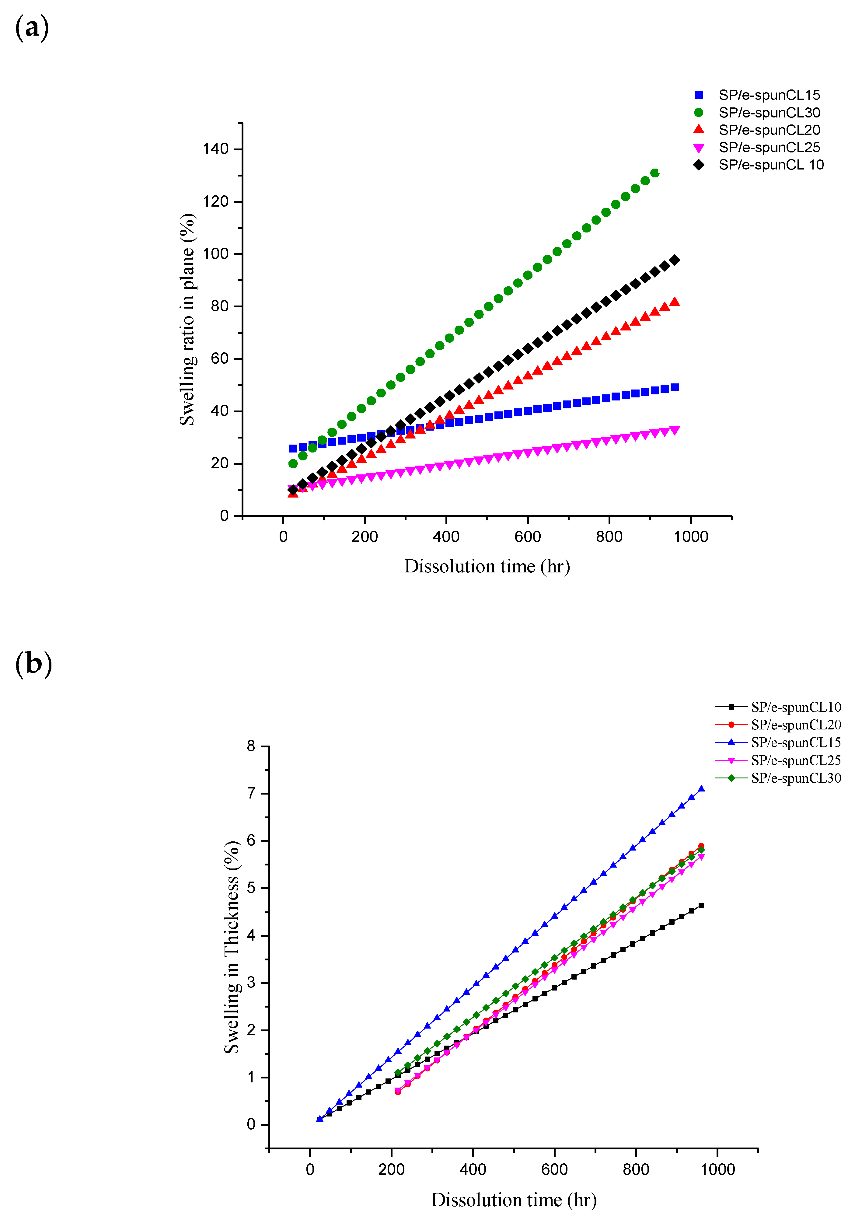
| Sample | Weight Dry (mg) | Weight Wet (mg) | Thickness Dry (mm) | Thickness Wet (mm) | Diameter Dry (mm) | Diameter Wet (mm) | Percentage of Water Uptake and Dimensional Changes (%) | ||
|---|---|---|---|---|---|---|---|---|---|
| Water Uptake (%) | Swelling in Thickness (%) | Swelling in Plane (%) | |||||||
| SP/e-spunCL10 | 0.02 ± 0.65 | 0.026 ± 0.23 | 0.02 ± 0.65 | 0.022 ± 0.43 | 25.87 ± 0.54 | 25.9 ± 0.23 | 30 | 7.8 | 0.116 |
| SP/e-spunCL15 | 0.01 ± 0.78 | 0.0126 ± 0.08 | 0.009 ± 0.06 | 0.011 ± 0.07 | 16.78 ± 0.65 | 16.8 ± 0.05 | 25.87 | 8.9 | 0.119 |
| SP/e-spunCL20 | 0.03 ± 0.54 | 0.037 ± 0.76 | 0.024 ± 0.56 | 0.026 ± 0.05 | 17.876 ± 0.02 | 18 ± 0.06 | 24.56 | 8.33 | 0.694 |
| SP/e-spunCL25 | 0.01 ± 0.64 | 0.012 ± 0.09 | 0.078 ± 0.21 | 0.163 ± 0.04 | 18.86 ± 0.97 | 19 ± 0.65 | 20 | 11 | 0.742 |
| SP/e-spunCL30 | 0.01 ± 0.43 | 0.0119 ± 0.87 | 0.015 ± 0.32 | 0.018 ± 0.65 | 19.78 ± 0.34 | 20 ± 0.76 | 19 | 20 | 1.112 |
| Reference Number | Materials | OCV (V) | Current (mAcm−2) | Power Density (Wcm−2) |
|---|---|---|---|---|
| [47] | PVDF/(PMMA-co-PAMPS)/SiO2 | 0.243 | 140.00 | 0.034.3 |
| [48] | SPEEK (DS 67%) | 1.006 | 672.00 | 0.191 |
| [48] | SPEEK/CN-0.5 | 1.020 | 832.00 | 0.266 |
| [49] | SPEEK-Sulfonation of fullerene (Sfu) | 0.1 | 100.00 | 0.103 |
| [50] | SPEEK-0.77% tetra(4-pyridyl)porphyrin (TPyP) (TPyP) | 1.108 | 2.4 × 10⁻⁴ | 0.093 |
| [51] | Electrospun phthalazinone ether sulfone ketone (SPPESK)/IEC1.72 | 0.92 | 350.00 | 1.000 |
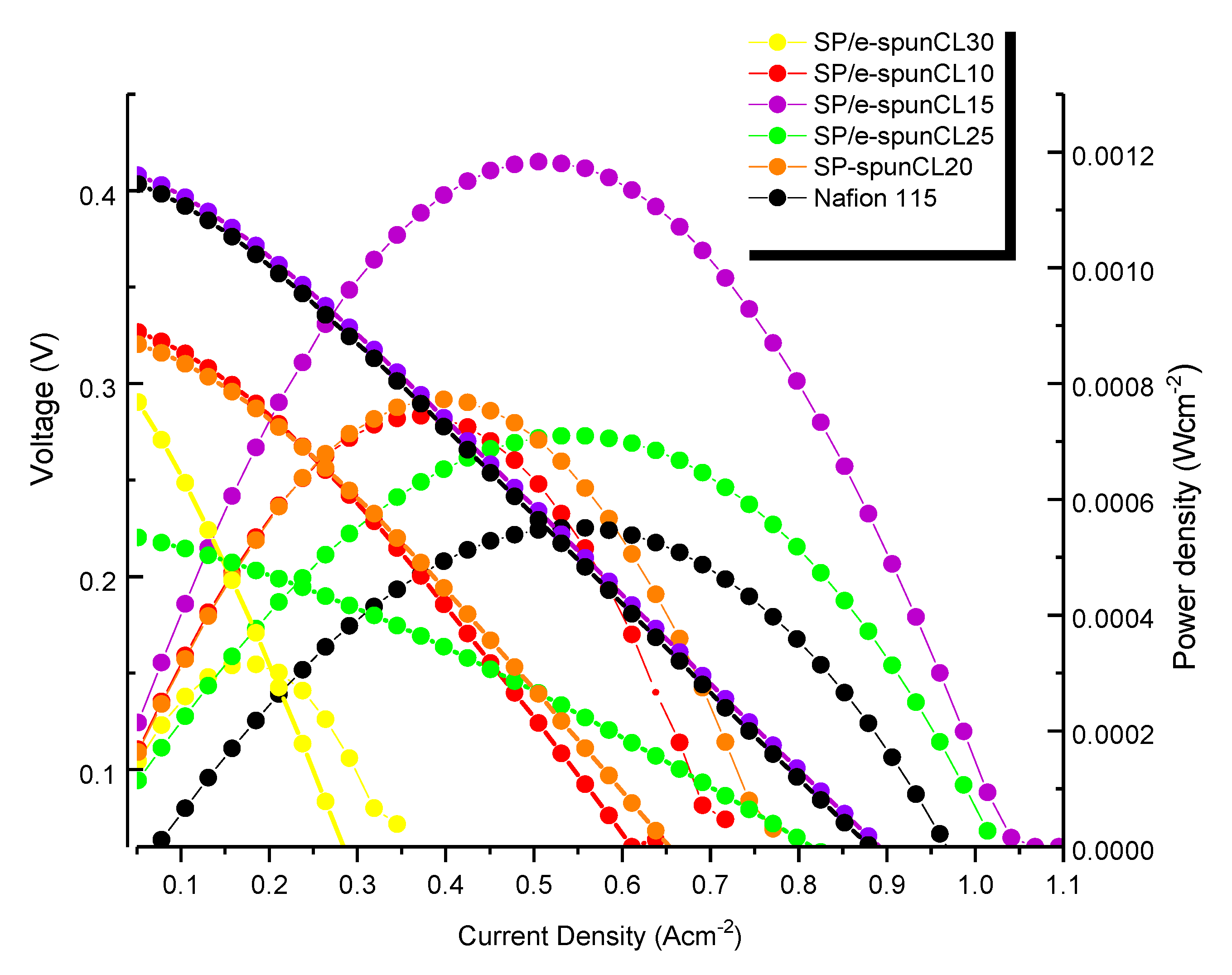
| - | Nafion® 115 | 0.403 | 961.50 | 0.00055 |
| - | SP/e-spunCL15 | 0.412 | 1042.20 | 0.00118 |
© 2019 by the authors. Licensee MDPI, Basel, Switzerland. This article is an open access article distributed under the terms and conditions of the Creative Commons Attribution (CC BY) license (http://creativecommons.org/licenses/by/4.0/).
Share and Cite
Awang, N.; Jaafar, J.; Ismail, A.F.; Othman, M.H.D.; Rahman, M.A. Performance of Void-Free Electrospun SPEEK/Cloisite as a Function of Degree of Dispersion State on Nanocomposite Proton Exchange Membrane for Direct Methanol Fuel Cell Application. Membranes 2019, 9, 7. https://doi.org/10.3390/membranes9010007
Awang N, Jaafar J, Ismail AF, Othman MHD, Rahman MA. Performance of Void-Free Electrospun SPEEK/Cloisite as a Function of Degree of Dispersion State on Nanocomposite Proton Exchange Membrane for Direct Methanol Fuel Cell Application. Membranes. 2019; 9(1):7. https://doi.org/10.3390/membranes9010007
Chicago/Turabian StyleAwang, Nuha, Juhana Jaafar, Ahmad Fauzi Ismail, Mohd Hafiz Dzarfan Othman, and Mukhlis A. Rahman. 2019. "Performance of Void-Free Electrospun SPEEK/Cloisite as a Function of Degree of Dispersion State on Nanocomposite Proton Exchange Membrane for Direct Methanol Fuel Cell Application" Membranes 9, no. 1: 7. https://doi.org/10.3390/membranes9010007
APA StyleAwang, N., Jaafar, J., Ismail, A. F., Othman, M. H. D., & Rahman, M. A. (2019). Performance of Void-Free Electrospun SPEEK/Cloisite as a Function of Degree of Dispersion State on Nanocomposite Proton Exchange Membrane for Direct Methanol Fuel Cell Application. Membranes, 9(1), 7. https://doi.org/10.3390/membranes9010007


