Pilot–Scale Production of Carbon Hollow Fiber Membranes from Regenerated Cellulose Precursor-Part II: Carbonization Procedure


Abstract
:1. Introduction
2. Experimental
2.1. Preparation of Precursor Fibers
2.2. Fiber Loading in the Furnace and Carbonization Procedure
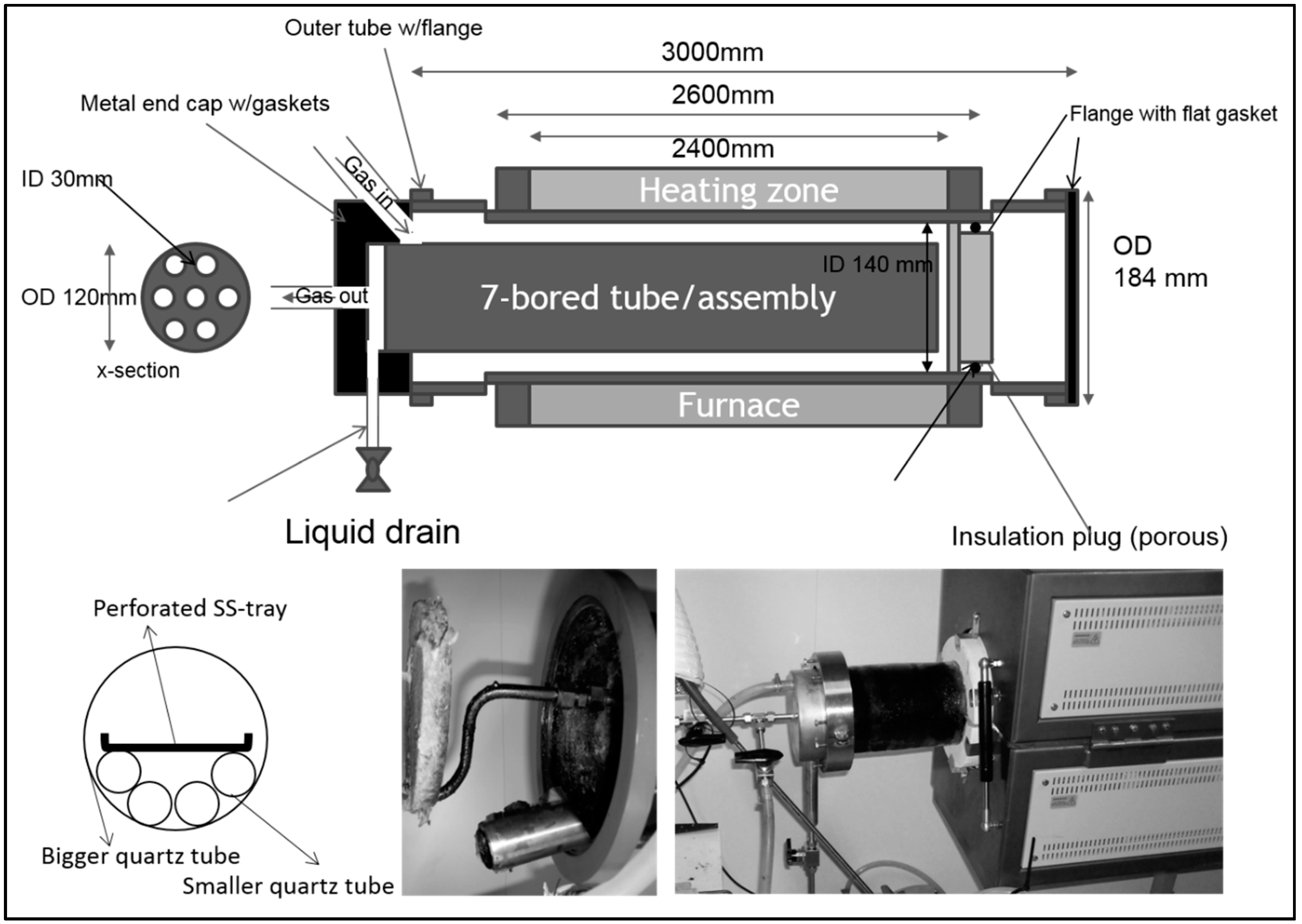
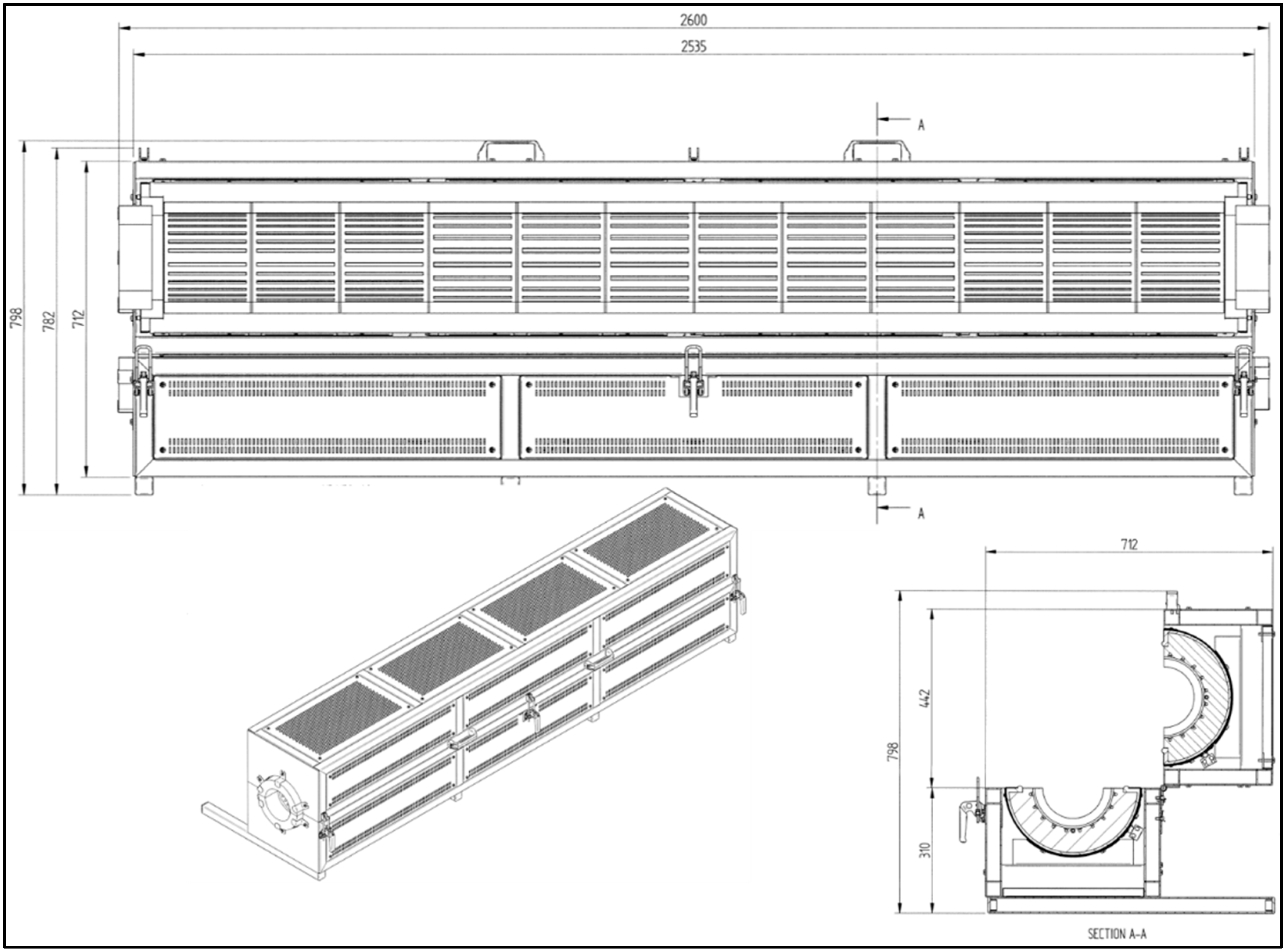
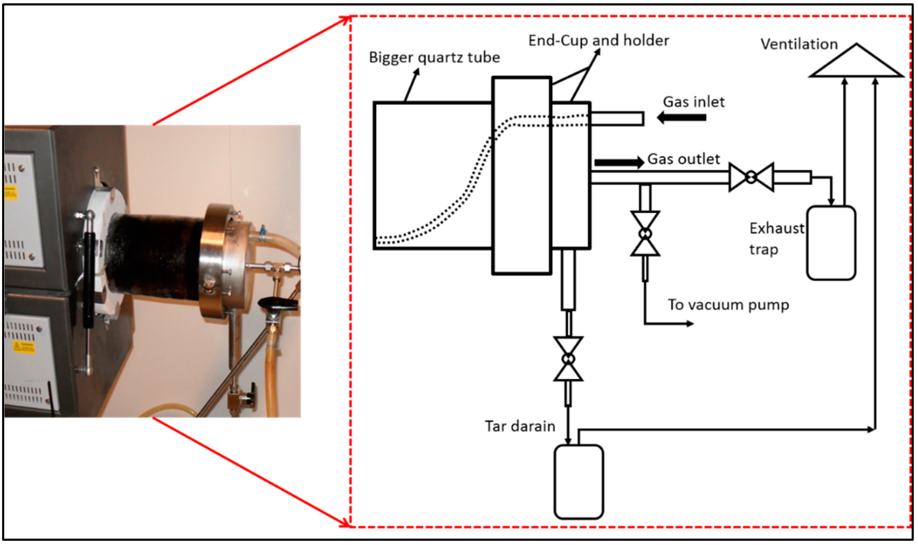
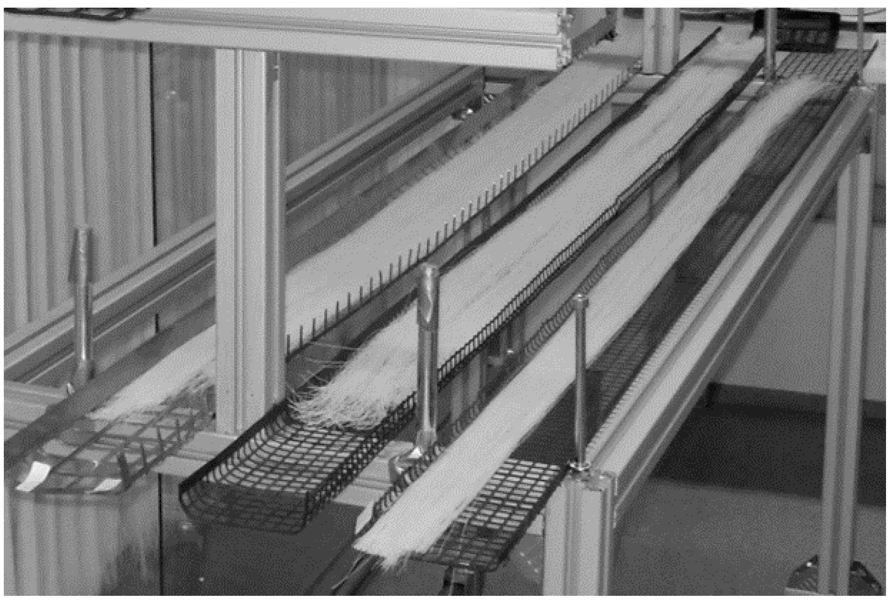
2.2.1. Description of the Furnace
2.2.2. Procedure for Carbonization
Loading the Furnace
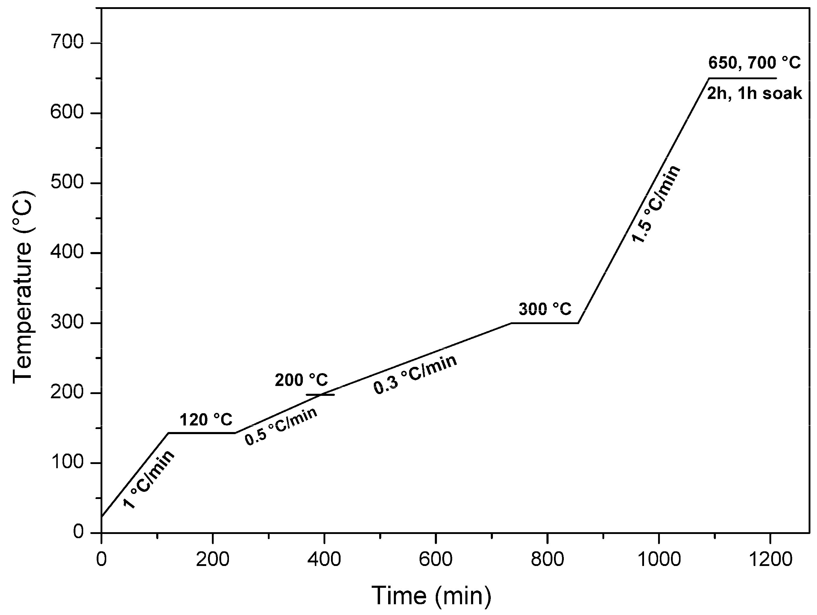
Carbonization
2.3. Permeation Testing
3. Results and Discussion
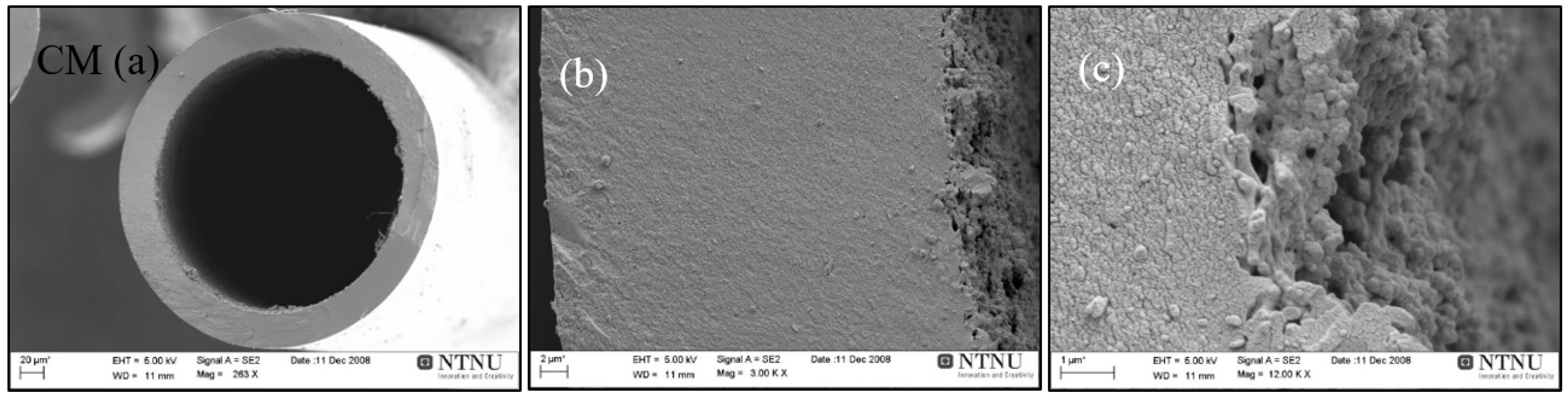
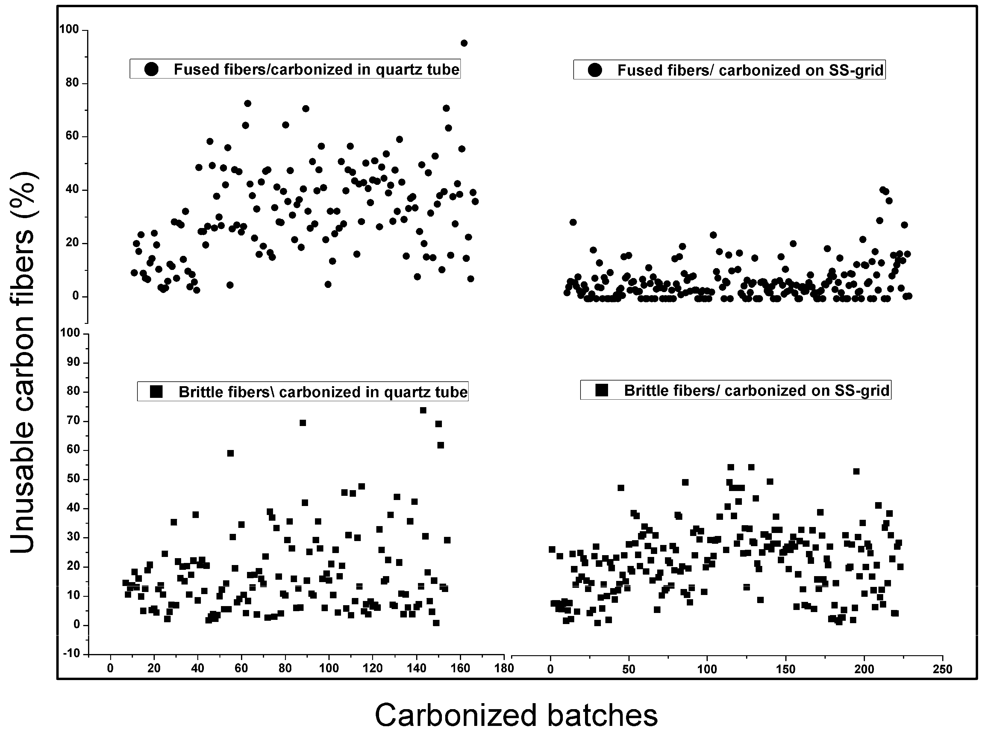
3.1. Fiber Morphology and Successful Fibers
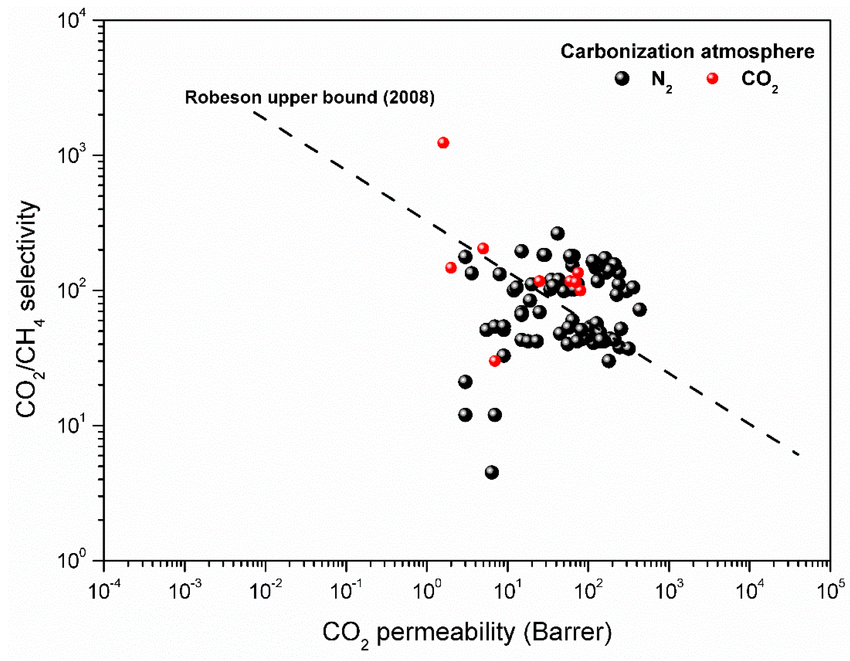
3.2. Gas Permeation Properties
4. Conclusions
Author Contributions
Funding
Acknowledgments
Conflicts of Interest
References
- Baker, R.W. Future directions of membrane gas separation technology. Ind. Eng. Chem. Res. 2002, 41, 1393–1411. [Google Scholar] [CrossRef]
- Yan, S.; Fang, M.; Zhang, W.; Zhong, W.; Luo, Z.; Cen, K. Comparative analysis of CO2 separation from flue gas by membrane gas absorption technology and chemical absorption technology in china. Energy Convers. Manag. 2008, 49, 3188–3197. [Google Scholar] [CrossRef]
- Koresh, J.; Soffer, A. Study of molecular sieve carbons. Part 1.—Pore structure, gradual pore opening and mechanism of molecular sieving. J. Chem. Soc. Faraday Trans. 1 1980, 76, 2457–2471. [Google Scholar] [CrossRef]
- Koresh, J.; Soffer, A. Study of molecular sieve carbons. Part 2.-estimation of cross-sectional diameters of non-spherical molecules. J. Chem. Soc. Faraday Trans. 1 1980, 76, 2472–2485. [Google Scholar] [CrossRef]
- Koresh, J.E.; Sofer, A. Molecular sieve carbon permselective membrane. Part I. Presentation of a new device for gas mixture separation. Sep. Sci. Technol. 1983, 18, 723–734. [Google Scholar] [CrossRef]
- Koresh, J.E.; Soffer, A. Mechanism of permeation through molecular-sieve carbon membrane. Part 1.—The effect of adsorption and the dependence on pressure. J. Chem. Soc. Faraday Trans. 1 1986, 82, 2057–2063. [Google Scholar] [CrossRef]
- Robeson, L.M. The upper bound revisited. J. Membr. Sci. 2008, 320, 390–400. [Google Scholar] [CrossRef]
- Tin, P.S.; Chung, T.-S.; Hill, A.J. Advanced fabrication of carbon molecular sieve membranes by nonsolvent pretreatment of precursor polymers. Ind. Eng. Chem. Res. 2004, 43, 6476–6483. [Google Scholar] [CrossRef]
- Ismail, A.F.; David, L.I.B. A review on the latest development of carbon membranes for gas separation. J. Membr. Sci. 2001, 193, 1–18. [Google Scholar] [CrossRef]
- Salleh, W.N.W.; Ismail, A.F. Carbon membranes for gas separation processes: Recent progress and future perspective. J. Membr. Sci. Res. 2015, 1, 2–15. [Google Scholar] [CrossRef]
- Kiyono, M.; Williams, P.J.; Koros, W.J. Effect of polymer precursors on carbon molecular sieve structure and separation performance properties. Carbon 2010, 48, 4432–4441. [Google Scholar] [CrossRef]
- Jon Arvid Lie, M.-B.H. Carbon Membranes. U.S. Patents US20100162887 A1, 1 July 2010. [Google Scholar]
- He, X.; Hägg, M.-B. Structural, kinetic and performance characterization of hollow fiber carbon membranes. J. Membr. Sci. 2012, 390–391, 23–31. [Google Scholar] [CrossRef]
- He, X.; Lie, J.A.; Sheridan, E.; Hägg, M.-B. Preparation and characterization of hollow fiber carbon membranes from cellulose acetate precursors. Ind. Eng. Chem. Res. 2011, 50, 2080–2087. [Google Scholar] [CrossRef]
- Lie, J.A. Synthesis, Performance and Regeneration of Carbon Membranes for Biogas Upgrading—A Future Energy Carrier. Ph.D. Thesis, Norwegian University of Science and Technology, Trondheim, Norway, 2005. [Google Scholar]
- Jones, C.W.; Koros, W.J. Characterization of ultramicroporous carbon membranes with humidified feeds. Ind. Eng. Chem. Res. 1995, 34, 158–163. [Google Scholar] [CrossRef]
- Lie, J.A.; Hägg, M.-B. Carbon membranes from cellulose: Synthesis, performance and regeneration. J. Membr. Sci. 2006, 284, 79–86. [Google Scholar] [CrossRef]
- Lie, J.A.; Hägg, M.-B. Carbon membranes from cellulose and metal loaded cellulose. Carbon 2005, 43, 2600–2607. [Google Scholar] [CrossRef]
- Menendez, I.; Fuertes, A.B. Aging of carbon membranes under different environments. Carbon 2001, 39, 733–740. [Google Scholar] [CrossRef]
- Xu, L.; Rungta, M.; Hessler, J.; Qiu, W.; Brayden, M.; Martinez, M.; Barbay, G.; Koros, W.J. Physical aging in carbon molecular sieve membranes. Carbon 2014, 80, 155–166. [Google Scholar] [CrossRef]
- Lagorsse, S.; Campo, M.C.; Magalhães, F.D.; Mendes, A. Water adsorption on carbon molecular sieve membranes: Experimental data and isotherm model. Carbon 2005, 43, 2769–2779. [Google Scholar] [CrossRef]
- Sanyal, O.; Zhang, C.; Wenz, G.B.; Fu, S.; Bhuwania, N.; Xu, L.; Rungta, M.; Koros, W.J. Next generation membranes—Using tailored carbon. Carbon 2018, 127, 688–698. [Google Scholar] [CrossRef]
- Ma, X.; Swaidan, R.; Teng, B.; Tan, H.; Salinas, O.; Litwiller, E.; Han, Y.; Pinnau, I. Carbon molecular sieve gas separation membranes based on an intrinsically microporous polyimide precursor. Carbon 2013, 62, 88–96. [Google Scholar] [CrossRef]
- Soffer, A.; Koresh, J.E.; Saggy, S. Separation Device. U.S. Patents US4685940A, 11 August 1987. [Google Scholar]
- Haider, S.; Lindbråthen, A.; Lie, J.A.; Andersen, I.C.T.; Hägg, M.-B. CO2 separation with carbon membranes in high pressure and elevated temperature applications. Sep. Purif. Technol. 2018, 190, 177–189. [Google Scholar] [CrossRef]
- Salleh, W.N.W.; Ismail, A.F. Carbon hollow fiber membranes derived from pei/pvp for gas separation. Sep. Purif. Technol. 2011, 80, 541–548. [Google Scholar] [CrossRef]
- Haider, S.; Lindbråthen, A.; Hägg, M.-B. Techno-economical evaluation of membrane based biogas upgrading system: A comparison between polymeric membrane and carbon membrane technology. Green Energy Environ. 2016, 1, 222–234. [Google Scholar] [CrossRef]
- Qin, J.-J.; Li, Y.; Lee, L.-S.; Lee, H. Cellulose acetate hollow fiber ultrafiltration membranes made from ca/pvp 360 k/nmp/water. J. Membr. Sci. 2003, 218, 173–183. [Google Scholar] [CrossRef]
- Son, W.K.; Youk, J.H.; Lee, T.S.; Park, W.H. Electrospinning of ultrafine cellulose acetate fibers: Studies of a new solvent system and deacetylation of ultrafine cellulose acetate fibers. J. Polym. Sci. Part B 2004, 42, 5–11. [Google Scholar] [CrossRef]
- Kawamoto, H.; Murayama, M.; Saka, S. Pyrolysis Behavior of Levoglucosan as an Intermediate in Cellulose Pyrolysis: Polymerization Into Polysaccharide as a Key Reaction to Carbonized Product Formation. J. Wood Sci. 2003, 49, 469–473. Available online: https://link.springer.com/article/10.1007/s10086-002-0487-5 (accessed on 13 October 2018). [CrossRef]
- Soffer, A.; Gilron, J.; Saguee, S.; Hed-Ofek, R.; Cohen, H. Process for the Production of Hollow Carbon Fiber Membranes. Patents EP0671202B1, 4 July 2001. [Google Scholar]
- Drioli, E.; Barbieri, G.; Brunetti, A. Membrane Engineering for the Treatment of Gases: Gas Separation Issues with Membranes; RSC Publishing: Cambridge, UK, 2011; Volume 2, p. 180. ISBN 978-1-78262-874-3. [Google Scholar]
- Lagorsse, S.; Magalhães, F.D.; Mendes, A. Carbon molecular sieve membranes: Sorption, kinetic and structural characterization. J. Membr. Sci. 2004, 241, 275–287. [Google Scholar] [CrossRef]
- He, X.; Arvid Lie, J.; Sheridan, E.; Hägg, M.-B. CO2 capture by hollow fibre carbon membranes: Experiments and process simulations. Energy Procedia 2009, 1, 261–268. [Google Scholar] [CrossRef]
- He, X.; Hägg, M.-B. Hollow fiber carbon membranes: Investigations for CO2 capture. J. Membr. Sci. 2011, 378, 1–9. [Google Scholar] [CrossRef]
- He, X.; Hägg, M.-B. Hollow fiber carbon membranes: From material to application. Chem. Eng. J. 2013, 215–216, 440–448. [Google Scholar] [CrossRef]
- Barton, T.J.; Bull, L.M.; Klemperer, W.G.; Loy, D.A.; McEnaney, B.; Misono, M.; Monson, P.A.; Pez, G.; Scherer, G.W.; Vartuli, J.C.; et al. Tailored porous materials. Chem. Mater. 1999, 11, 2633–2656. [Google Scholar] [CrossRef]
- Geiszler, V.C.; Koros, W.J. Effects of polyimide pyrolysis conditions on carbon molecular sieve membrane properties. Ind. Eng. Chem. Res. 1996, 35, 2999–3003. [Google Scholar] [CrossRef]
- Karvan, O.; Johnson, J.R.; Williams, P.J.; Koros, W.J. A pilot-scale system for carbon molecular sieve hollow fiber membrane manufacturing. Chem. Eng. Technol. 2013, 36, 53–61. [Google Scholar] [CrossRef]
- Lin, W.-H.; Vora, R.H.; Chung, T.-S. Gas transport properties of 6fda-durene/1,4-phenylenediamine (ppda) copolyimides. J. Polym. Sci. B Polym. Phys. 2000, 38, 2703–2713. [Google Scholar] [CrossRef]
- Koros, W.J.; Mahajan, R. Pushing the limits on possibilities for large scale gas separation: Which strategies? J. Membr. Sci. 2000, 175, 181–196. [Google Scholar] [CrossRef]
- Haider, S.; Lindbråthen, A.; Lie, J.A.; Hägg, M.-B. Carbon membranes for oxygen enriched air—Part II: Techno-economical analysis. Sep. Purif. Technol. 2018, 205, 251–262. [Google Scholar] [CrossRef]


© 2018 by the authors. Licensee MDPI, Basel, Switzerland. This article is an open access article distributed under the terms and conditions of the Creative Commons Attribution (CC BY) license (http://creativecommons.org/licenses/by/4.0/).
Share and Cite
Haider, S.; Lie, J.A.; Lindbråthen, A.; Hägg, M.-B. Pilot–Scale Production of Carbon Hollow Fiber Membranes from Regenerated Cellulose Precursor-Part II: Carbonization Procedure. Membranes 2018, 8, 97. https://doi.org/10.3390/membranes8040097
Haider S, Lie JA, Lindbråthen A, Hägg M-B. Pilot–Scale Production of Carbon Hollow Fiber Membranes from Regenerated Cellulose Precursor-Part II: Carbonization Procedure. Membranes. 2018; 8(4):97. https://doi.org/10.3390/membranes8040097
Chicago/Turabian StyleHaider, Shamim, Jon Arvid Lie, Arne Lindbråthen, and May-Britt Hägg. 2018. "Pilot–Scale Production of Carbon Hollow Fiber Membranes from Regenerated Cellulose Precursor-Part II: Carbonization Procedure" Membranes 8, no. 4: 97. https://doi.org/10.3390/membranes8040097
APA StyleHaider, S., Lie, J. A., Lindbråthen, A., & Hägg, M.-B. (2018). Pilot–Scale Production of Carbon Hollow Fiber Membranes from Regenerated Cellulose Precursor-Part II: Carbonization Procedure. Membranes, 8(4), 97. https://doi.org/10.3390/membranes8040097