Article

Al2O3 Disk Supported Si3N4 Hydrogen Purification Membrane for Low Temperature Polymer Electrolyte Membrane Fuel Cells

1
School of Chemical Engineering and Advanced Materials, Merz Court, Newcastle University, Newcastle upon Tyne NE1 7RU, UK
2
Department of Chemistry, University of Hull, Cottingham Road, Hull HU6 7RX, UK
*
Author to whom correspondence should be addressed.
Membranes 2013, 3(4), 406-414; https://doi.org/10.3390/membranes3040406
Submission received: 26 November 2013 / Accepted: 2 December 2013 / Published: 5 December 2013
(This article belongs to the Special Issue Advancements in Membranes for Electrochemical Energy Applications)

Abstract

:
Reformate gas, a commonly employed fuel for polymer electrolyte membrane fuel cells (PEMFCs), contains carbon monoxide, which poisons Pt-containing anodes in such devices. A novel, low-cost mesoporous Si3N4 selective gas separation material was tested as a hydrogen clean-up membrane to remove CO from simulated feed gas to single-cell PEMFC, employing Nafion as the polymer electrolyte membrane. Polarization and power density measurements and gas chromatography showed a clear effect of separating the CO from the gas mixture; the performance and durability of the fuel cell was thereby significantly improved.

1. Introduction

The hydrogen-fuelled, proton-exchange membrane fuel cell is a promising power source because of its high power density, high-energy conversion efficiency and low emission level. However, it requires high-purity H2 when operated at low temperatures, since impurities in the H2 stream, such as CO, will poison and therefore reduce the performance of Pt-based anodes. It has been reported that a CO concentration of 10 ppm and above will poison Pt [1,2]. A significant amount of research has been carried out to improve the CO tolerance by using advanced Pt alloy catalysts [3,4,5,6], or alternative membranes capable of operating at higher temperatures [7,8,9,10,11]. H2 purifying devices can also be used to remove CO, but the use of such additional steps has a negative effect on the overall process in terms of cost and efficiency [12,13].
The low-cost mesoporous silicon nitride (Si3N4) employed in this study, has a high surface area (≥400 m2 g−1, determined using the Brunauer–Emmett–Teller (BET) method [14]) and a narrow pore-size distribution (20–60 Å) [14,15]. The small pore size and large polar surface area of silicon nitride renders it of possible interest with respect to application as a selective gas filter [16]. The polar nature of the surface sites on silicon nitride also gives rise to complicated physisorption and chemisorption reactions which may influence its gas separation properties [17,18]. A thin mesoporous Si3N4 layer deposited on top of a microporous Al2O3 disk support has shown high selective absorption of NO2 [15], and also potential application in the separation of CO from reformate.
In the work reported in this paper, the Nafion membrane system was employed as the polymer electrolyte membrane (PEM) in the polymer electrolyte membrane fuel cells (PEMFCs) fuelled by a mix of CO and H2 passing through a Si3N4 membrane. Because it is clear to see the CO poisoning effect significantly reduces such fuel cell’s performance which operates at low temperatures.

2. Results and Discussion

2.1. Scanning Electron Microscopy
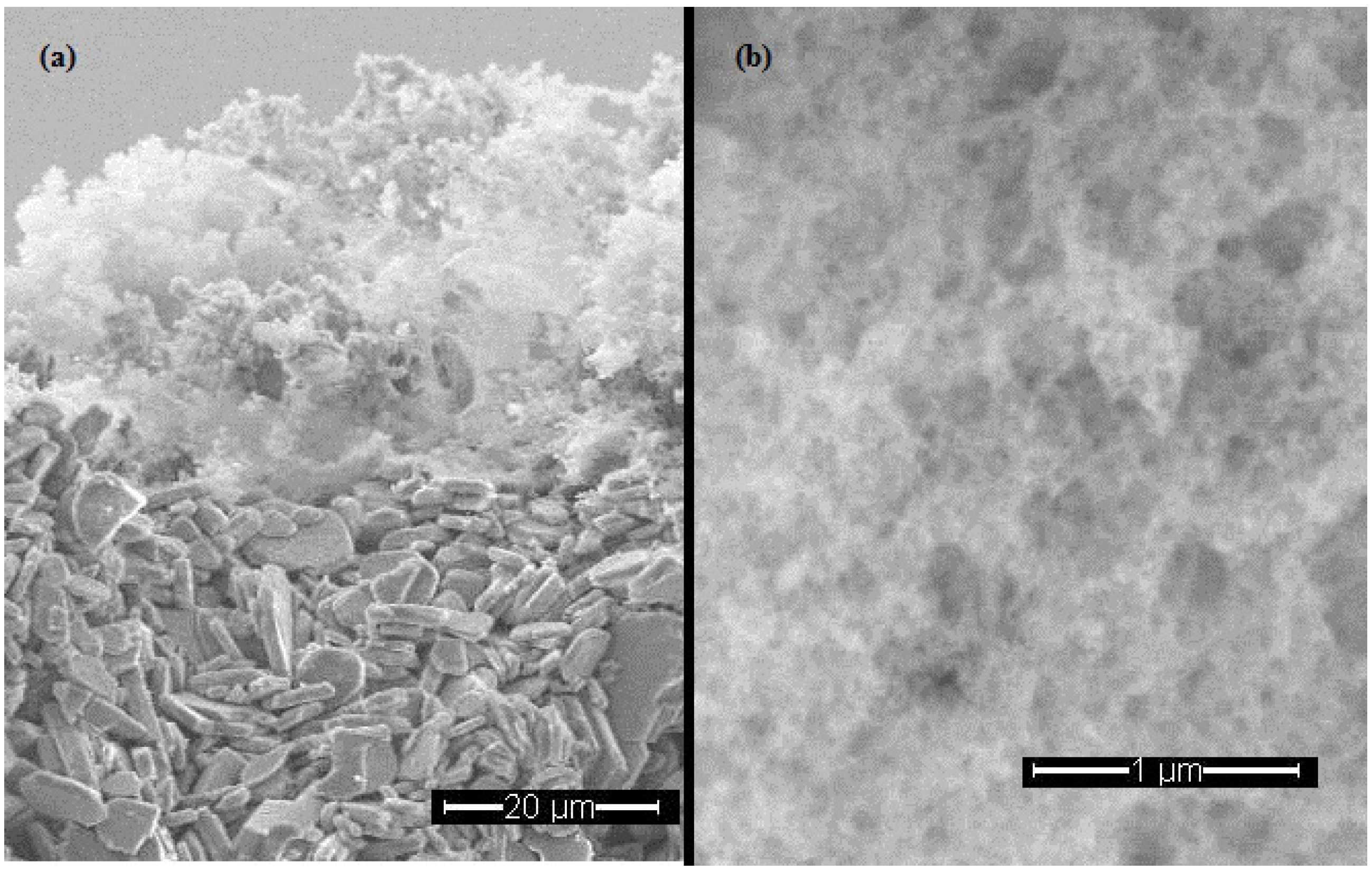
Figure 1a shows a scanning electron micrograph (SEM) image (×1000) of a cross-section of the Si3N4 membrane supported on Al2O3. A reasonably uniform Si3N4 appears on the top of the Al2O3 disk. As can be seen in the figure, the thickness of the Si3N4 layer was approximately 20 µm. Figure 1b shows the Si3N4 layer at higher magnification (×25,000) and it appears from the figure that the Si3N4 was highly porous and could possibly act as an effective absorbent for CO.
Figure 1. Scanning electron micrographs (SEMs) of the Si3N4 membrane supported on Al2O3.
Membranes 03 00406 g001

2.2. Gas Chromatography (GC)

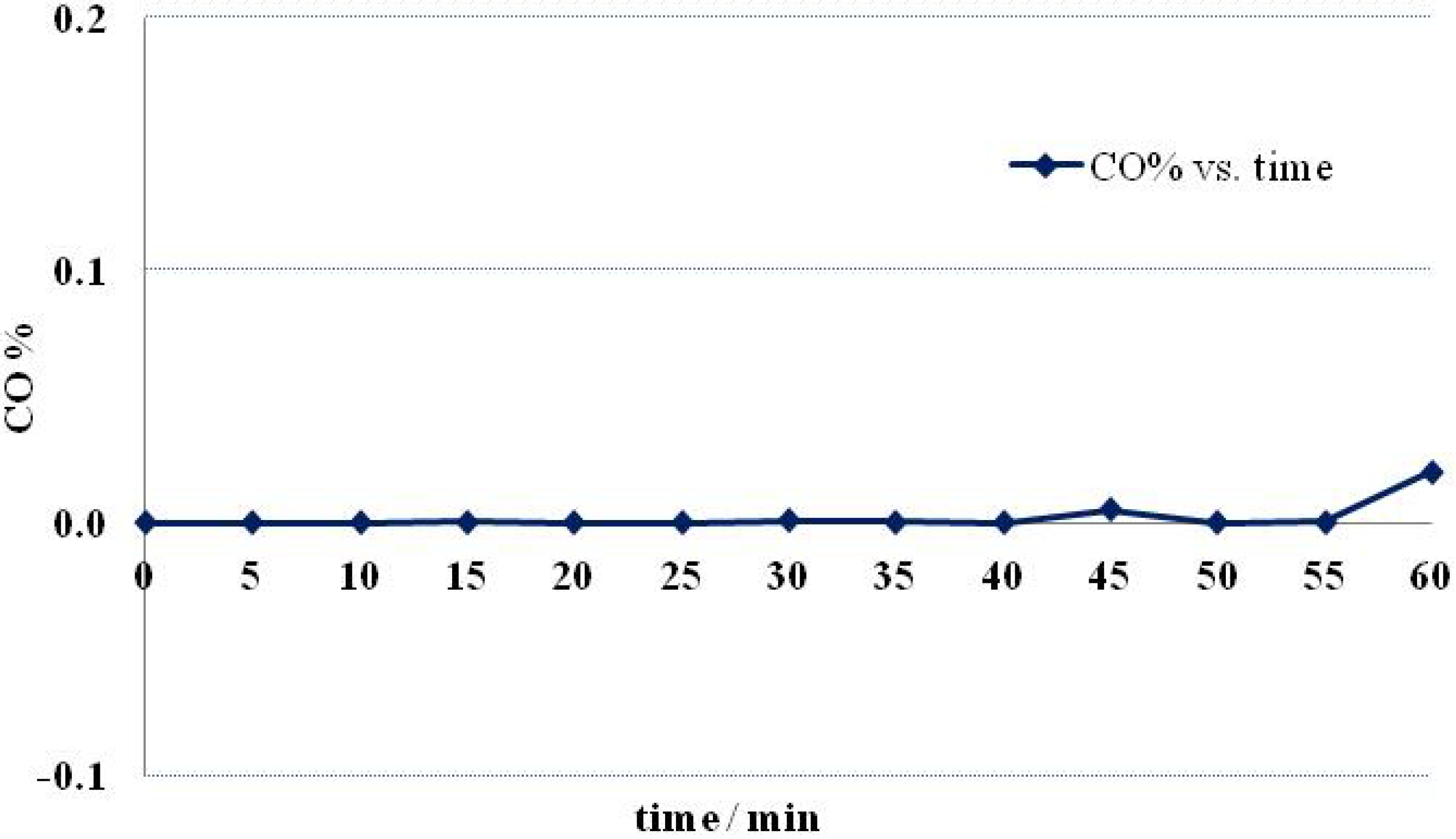
The concentration of CO in H2 in the exhaust from the filter H2 (CO%) was calculated from the GC spectra. Figure 2 shows CO% as a function of operation time. As may be seen from the figure, CO was not detected in the outlet gas for the first 40 min; at longer times, the CO concentration slightly increased, suggesting the filter may allow a tiny amount of CO to pass through. The separation phenomenon might be via mixed chemisorption and physisorption functions, but it cannot be identified at this stage. The majority of CO was blocked by the membrane and discharged from the bypass outlet. The tiny amount of CO that passed through the membrane may have resulted from the layer of Si3N4 being too thin. Increasing the amount of such material or packing it in a cartridge may be a possible solution.
Figure 2. The volumetric concentration of CO in the Si3N4 membrane-filtered gas as a function of time.
Membranes 03 00406 g002

2.3. Fuel Cell Testing

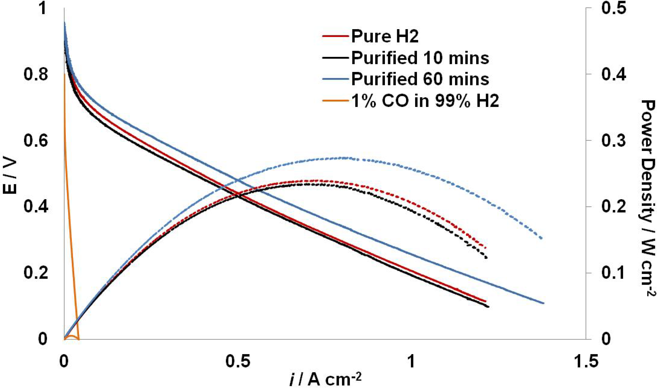
Figure 3 shows the polarization curves and power density curves of the fuel cell. The fuel cell was operated for 60 min with the filtered gas as anode feeding gas, the forward sweep at 10 min and 60 min are shown. The curve obtained using pure H2 as anode feeding gas in the same fuel cell is also included for comparison, as well as the curve obtained using 1% CO in 99% H2 as anode feeding gas. The operating temperature of the PBI system was 80 °C.
With pure H2, a maximum power density of 0.29 W cm−2 was achieved. The 1% CO in H2 mixture filtered through the Si3N4 membrane was then fed into the anode, replacing pure H2. The performance of the fuel cell was decreased with a maximum power density 0.24 W cm−2. As the bypass value was slightly open, the flow rate after the membrane would be lower than 300 cm3 min−1; presumably there was a small pressure drop too. This might be the reason for the lower fuel cell performance. However, after another 50 min operation, the fuel cell remained a similar performance with less than 0.01 W cm−2 decreases in maximum power density. This is the evidence that the CO concentration of the filtered gas was lower than 10 ppm; the majority of CO was separated by the membrane. However, longer operation time will be needed to verify the separating function of the Si3N4 membranes.
When the anode feeding gas switched to 1% CO in 99% H2, the fuel cell performance became affected from the very beginning, and it showed a complete CO poisoning effect to the anode catalyst.
Figure 3. Polarization (solid) and power density (dash) curves of the fuel cell. The blue curve fuel cell with pure H2 as the anode feed. The red curves represent the fuel cell with anode feeding gas of filtered mixed gas at 10 min and the black curves represent the curves obtained at 60 min. The orange curves represent the fuel cell performance with anode feeding gas of 1% CO in 99% H2.
Membranes 03 00406 g003

3. Experimental Section

3.1. Si3N4 Membrane

All chemicals were obtained from Sigma-Aldrich (Dorset, UK). The Al2O3 disks, as the membrane support, were prepared from Al2O3 powder using water as binder. The disks were then sintered at 1000 °C for 4 h. All procedures were performed under a protective nitrogen atmosphere using standard Schlenk techniques or in a nitrogen-filled glove box. The Si3N4 membranes were prepared by dipping Al2O3 support disks into a silicon di-imide sol followed by sintering [15,19]. Briefly, the silicon diimide sol was prepared by adding trifluoromethanesulfonic acid into a solution of TDSA in dry THF. The mixture was heated at 50 °C for 16 h then cool to room temperature. A solution of ammonia in cold THF was then added and the mixture left quiescent at room temperature for 18 h, then ammonia gas was bubbled through the solution for 10 min. After being left quiescent for 1 h, Al2O3 support disks were dipped in the sol for 10 min and then dried under N2 flow. After 30 min the disks were dipped again for another 10 min. The disks were dried under N2 flow overnight and then pyrolyzed under NH3 flow at 1000 °C for 2 h. The heating rate for the pyrolysis was 2 °C min−1. The disks so obtained were 1.6 cm in diameter, 0.1 cm in thickness, so that 4.5 cm2 in total surface area. On average, 9 mg of dry Si3N4 was deposited on each Al2O3 disk.

3.2. Scanning Electron Microscopy (SEM)

Scanning electron micrographs were obtained using a Philips XL30 ESEM-FEG SEM instrument. The Si3N4 membrane was imaged without any additional coating. The membrane was dipped in liquid nitrogen and then broken using pliers to obtain a clean cross-section.

3.3. The Membrane Holder

Figure 4 shows the holder cell for the Si3N4 membranes. The cell allowed a mixture of various compositions of CO and H2 to flow through the membrane at rates up to 300 cm3 min−1. The two chambers were made from poly(methyl methacrylate), and silicone rubber sheets were employed as gaskets to ensure a good seal between the holder and the Si3N4 membrane. The edge of the membrane was covered by silicone rubber, and the effective area of the membrane was 1.3 cm2. As it has been shown in Section 3.1 that each membrane has a surface area of 4.5 cm2, assuming Si3N4 was homogeneously deposited on the Al2O3 disk, then 37.6% of the Si3N4 was responsible for separating the CO.
Figure 4. The holder cell for the Si3N4 membrane.
Membranes 03 00406 g004

3.4. The Fuel Cell Test Rig

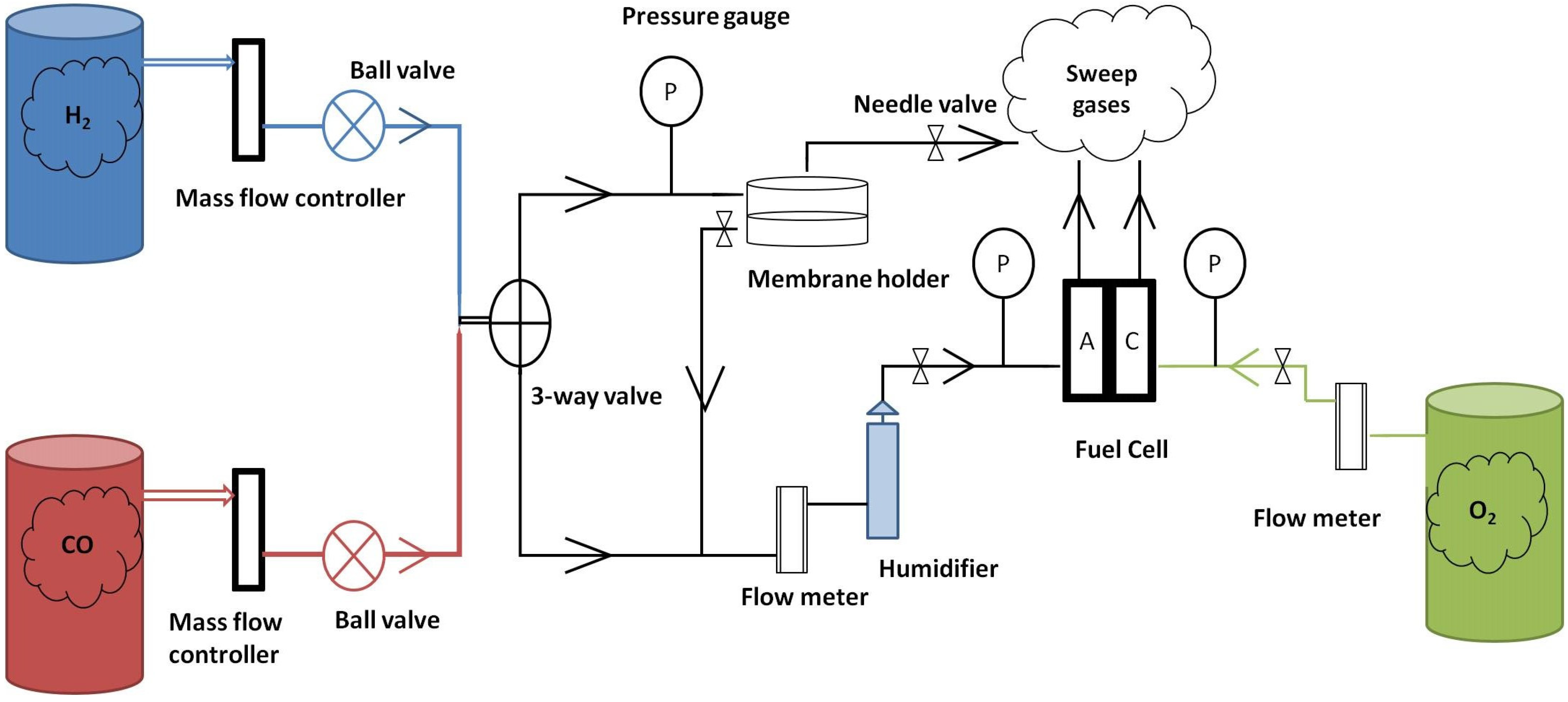
Figure 5 shows a schematic diagram of the fuel cell rig. The mass flow controllers were used to produce 1% CO in 99% H2 by volume for fuel cell test and gas chromatography (GC) test. The CO + H2 was fed to the Si3N4 membrane at a flow rate of 300 cm3 min−1 and then humidified by passing through a humidifier with di-ionized water maintained at 110 °C prior to entering the anode compartment of the PEMFC. The bypass needle value (marked as A in Figure 5) was slightly open to allow filtered CO exhausting and keep neutral pressure before the membrane in the cell. The cathode feed gas was pure oxygen at a flow rate of 300 mL min−1. The gas samples for GC were collected before entering the humidifier. All gasses were high purity (99.9%) and purchased from BOC Industrial Gases.
Figure 5. Schematic diagram of the fuel cell rig.
Membranes 03 00406 g005

3.5. GC

One percent CO in 99% H2 mixed gas at the rate of 300 mL min−1 was fed to the Si3N4 and then the exhaust gas samples were monitored using a SHIMADZU GC-8A Gas Chromatograph (Kyoto, Japan) fitted with a Molecular Sieve 5A column.

3.6. Fuel Cell and Membrane Electrolyte Assembly (MEA)
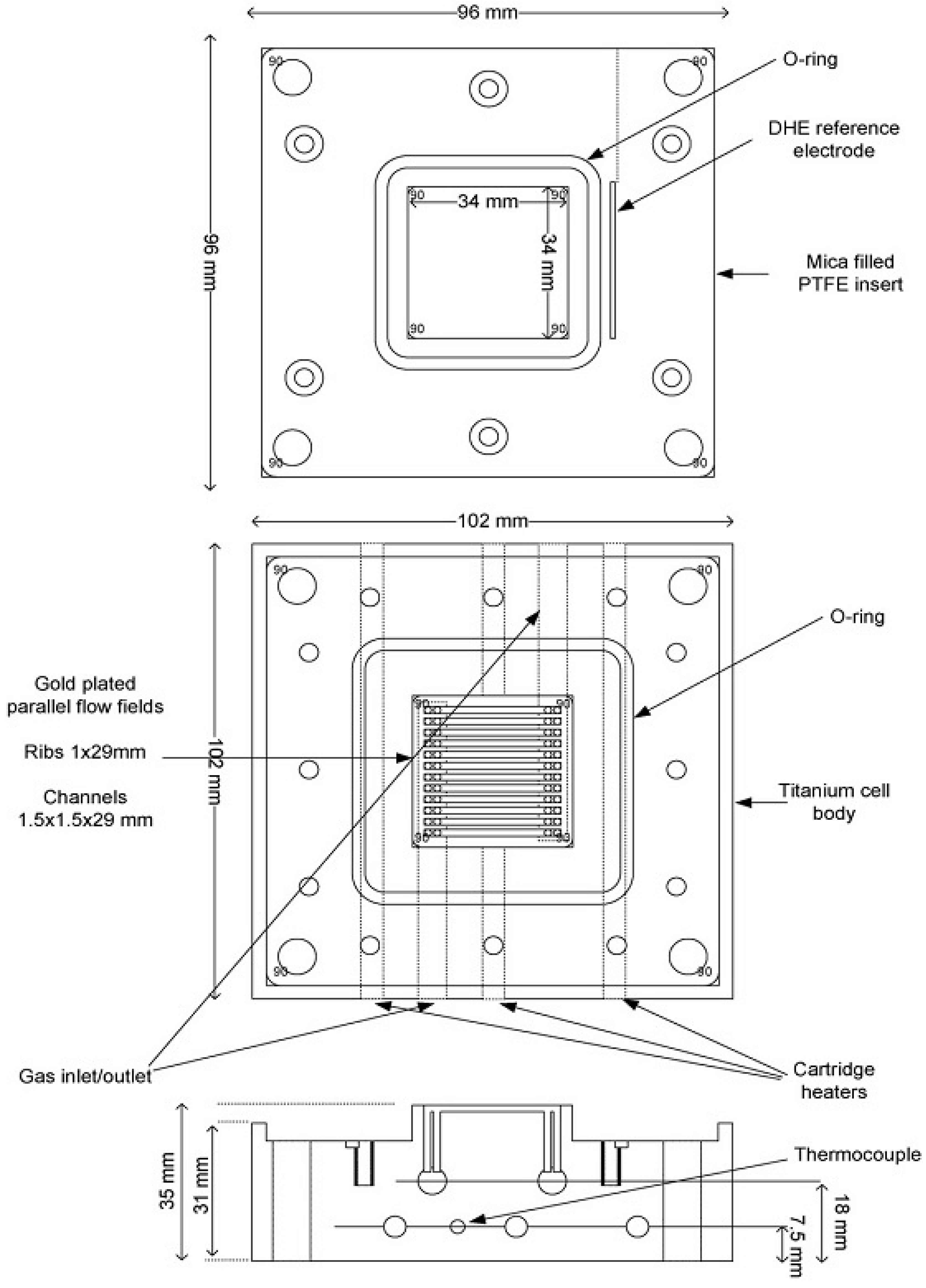
Details of the fuel cell employed may be found in previous papers [8,9,20]. Figure 6 shows a schematic diagram of the fuel cell. The cell body was made from titanium, the anode and cathode current collectors comprised 3.4 cm × 3.4 cm gold-plated Ti blocks, into which were cut parallel-flow fields to allow gases transport. Mica filled PTFE inserts were used to surround the flow fields and provide location for the O-ring seal and dynamic hydrogen electrodes (DHEs). The DHEs consisted of two platinum wires located on each side of the membrane outside the O-ring. Thermostatically controlled cartridge heaters (6 of 10 mm in diameter 100 mm in length, 150 W, RS, Northants, UK) were inserted into the Ti blocks to control the temperature. A 20 A potentiostat (Sycopel, UK) combined with a high impedance multi-channel data acquisition card (National Instruments, NI6010) was employed to carry out the electrochemical measurements. Polarisation curves were recorded during at a scan rate of 10 mV s−1.
The catalysts were purchased from Alfa Aesar. The anode was made from 20% Pt/C (VulcanXC-72) with a Pt loading of 0.2 mg cm−2. The cathode was made from 50% Pt/C (VulcanXC-72) with a Pt loading of 0.5 mg cm−2. 60% PTFE solution in di-ionized water (Sigma-Aldrich, Dorset, UK) was used as binder. The gas diffusion layer was made of carbon paper (10% GDL, 40% MPL, H2315T10AC) sourced from Freudenberg FCCT KG. Taking the anode preparation as an example, the ink was made by adding a small amount of de-ionized water into PTFE solution (20.4 mg) and mixing in a glass sample holder, followed by ultra-sonication for 15 min. The required amount of Pt/C catalyst (49.0 mg) and isopropanol (130.6 mg) were added to the aqueous PTFE solution, the suspension was then placed in the ultrasonic bath for a further 30 min. The preparation was carried out at room temperature. The carbon paper was heated on a hot plate to maintain the temperature at 80 °C to 100 °C for good liquid evaporation. The ink was sprayed evenly onto the surface of the carbon paper using a Badger Model 100™ spray gun fed by N2 gas. The Nafion 117 membrane was sandwiched between the cathode and the anode, and then hot pressed for 3 min at a pressure of 500 kg and temperature of 100 °C.
Figure 6. Schematic diagram of the fuel cell.
Membranes 03 00406 g006

4. Conclusions

It has been shown that an Al2O3-supported Si3N4 membrane was capable of separating CO from a mixed stream of CO and H2. The separation phenomenon could be achieved via mixed chemisorption and physisorption functions. The separated CO was discharged from the bypass gas outlet so that the pressure in the cell remained the same as the surrounding atmosphere. A pore size of Si3N4 could also block CO molecules and still allow H2 to pass through the membrane. Since Si3N4 has the advantages of being low cost and with ease of fabrication, it is probable that increasing the amount of Si3N4 used or changing the fabrication method would further improve the efficiency of the Si3N4 membrane to clean CO from a stream of H2.

Acknowledgments

We would like to thank EPSRC (ref. number RES05307354) for the financial support.

Conflicts of Interest

The authors declare no conflict of interest.

References

  1. Lemons, R.A. Fuel cells for transportation. J. Power Sources 1990, 29, 251–264. [Google Scholar] [CrossRef]
  2. Iulianelli, A.; Longo, T.; Basile, A. Methanol steam reforming reaction in a Pd–Ag membrane reactor for CO-free hydrogen production. Int. J. Hydrog. Energy 2008, 33, 5583–5588. [Google Scholar] [CrossRef]
  3. Avgouropoulos, G.; Ioannides, T. CO tolerance of Pt and Rh catalysts: Effect of CO in the gas-phase oxidation of H2 over Pt and Rh supported catalysts. Appl. Catal. B Environ. 2005, 56, 77–86. [Google Scholar] [CrossRef]
  4. Pereira, L.G.S.; Paganin, V.A.; Ticianelli, E.A. Investigation of the CO tolerance mechanism at several Pt-based bimetallic anode electrocatalysts in a PEM fuel cell. Electrochim. Acta 2009, 54, 1992–1998. [Google Scholar] [CrossRef]
  5. Tang, Y.; Zhang, H.; Zhong, H.; Xu, Z. In-situ investigation on the CO tolerance of carbon supported Pd–Pt electrocatalysts with low Pt content by electrochemical impedance spectroscopy. Int. J. Hydrog. Energy 2012, 37, 2129–2136. [Google Scholar] [CrossRef]
  6. Uchida, H.; Ozuka, H.; Watanabe, M. Electrochemical quartz crystal microbalance analysis of CO-tolerance at Pt–Fe alloy electrodes. Electrochim. Acta 2002, 47, 3629–3636. [Google Scholar] [CrossRef]
  7. Li, M.-Q.; Shao, Z.-G.; Scott, K. A high conductivity Cs2.5H0.5PMo12O40/polybenzimidazole (PBI)/H3PO4 composite membrane for proton-exchange membrane fuel cells operating at high temperature. J. Power Sources 2008, 183, 69–75. [Google Scholar] [CrossRef]
  8. Mamlouk, M.; Scott, K. The effect of electrode parameters on performance of a phosphoric acid-doped PBI membrane fuel cell. Int. J. Hydrog. Energy 2010, 35, 784–793. [Google Scholar] [CrossRef]
  9. Mamlouk, M.; Scott, K. An investigation of Pt alloy oxygen reduction catalysts in phosphoric acid doped PBI fuel cells. J. Power Sources 2011, 196, 1084–1089. [Google Scholar] [CrossRef]
  10. Sousa, T.; Mamlouk, M.; Scott, K. A dynamic non-isothermal model of a laboratory intermediate temperature fuel cell using PBI doped phosphoric acid membranes. Int. J. Hydrog. Energy 2010, 35, 12065–12080. [Google Scholar] [CrossRef]
  11. Sousa, T.; Mamlouk, M.; Scott, K. An isothermal model of a laboratory intermediate temperature fuel cell using PBI doped phosphoric acid membranes. Chem. Eng. Sci. 2010, 65, 2513–2530. [Google Scholar] [CrossRef]
  12. Peters, R.; Düsterwald, H.G.; Höhlein, B. Investigation of a methanol reformer concept considering the particular impact of dynamics and long-term stability for use in a fuel-cell-powered passenger car. J. Power Sources 2000, 86, 507–514. [Google Scholar] [CrossRef]
  13. Pettersson, L.J.; Westerholm, R. State of the art of multi-fuel reformers for fuel cell vehicles: Problem identification and research needs. Int. J. Hydrog. Energy 2001, 26, 243–264. [Google Scholar] [CrossRef]
  14. Cheng, F.; Clark, S.; Kelly, S.M.; Bradley, J.S.; Lefebvre, F. Preparation of mesoporous silicon nitride via a nonaqueous sol–gel route. J. Am. Ceram. Soc. 2004, 87, 1413–1417. [Google Scholar] [CrossRef]
  15. Cheng, F.; Kelly, S.M.; Clark, S.; Bradley, J.S.; Baumbach, M.; Schütze, A. Preparation and characterization of a supported Si3N4 membrane via a non-aqueous sol–gel process. J. Membr. Sci. 2006, 280, 530–535. [Google Scholar] [CrossRef]
  16. Kuraoka, K.; Kubo, N.; Yazawa, T. Microporous silica xerogel membrane with high selectivity and high permeance for carbon dioxide separation. J. Sol-Gel Sci. Technol. 2000, 19, 515–518. [Google Scholar] [CrossRef]
  17. Mori, H.; Mase, S.; Yoshimura, N.; Hotta, T.; Ayama, K.; Tsubaki, J.I. Fabrication of supported Si3N4 membranes using the pyrolysis of liquid polysilazane precursor. J. Membr. Sci. 1998, 147, 23–33. [Google Scholar] [CrossRef]
  18. Tong, H.D.; Jansen, H.V.; Gadgil, V.J.; Bostan, C.G.; Berenschot, E.; van Rijn, C.J.M.; Elwenspoek, M. Silicon nitride nanosieve membrane. Nano Lett. 2004, 4, 283–287. [Google Scholar] [CrossRef]
  19. Rovai, R.; Lehmann, C.W.; Bradley, J.S. Non-oxide sol–gel chemistry: Preparation from tris(dialkylamino)silazanes of a carbon-free, porous, silicon diimide gel. Angew. Chem. Int. Ed. 1999, 38, 2036–2038. [Google Scholar] [CrossRef]
  20. Mamlouk, M.; Scott, K. Analysis of high temperature polymer electrolyte membrane fuel cell electrodes using electrochemical impedance spectroscopy. Electrochim. Acta 2011, 56, 5493–5512. [Google Scholar] [CrossRef]