1. Introduction
The application of ultrafiltration (UF) capillary membranes in water treatment increases exponentially and has become more and more important in industrial fluid separations. It is a promising technology widely employed to enhance the purity and safety of drinking water [
1] since it offers the advantages of high efficiency with the use of mainly physical processes,
i.e., in many cases without additives of chemicals and relatively low operational costs and energy consumption [
2]. However, the process is limited by membrane fouling caused by physical and/or chemical interactions between the membrane and particulate matter existing in the feed water [
3]. The accumulation of these particles during filtration forms a cake layer, which creates additional resistance and contributes to the reduction of permeability of the membrane. The formation of this layer was studied in the presence of adhesive forces on the membrane surface and on different distributed membrane pore sizes [
4]. A new model was developed for crossflow filtration of polydisperse particles [
5] to investigate the factors influencing the cake formation during the filtration process and the cake growth on non-uniform permeable membranes [
6,
7]. CFD simulations allow better insight into transport mechanisms of particles and consequently offer numerous improvement possibilities on the membrane process including new membrane materials and configurations, determining operation conditions for optimum selectivity and defining the permeate flux to minimize fouling [
8]. The total permeate flux of crossflow microfiltration membranes is predicted by 3-dimensional CFD simulations to obtain the pressure distribution upon the membrane surface [
9]. The accumulation of particles on porous surfaces during crossflow filtration is described by modeling the colloidal phase transition into condensed phase [
10,
11]. Coupling Navier-Stokes and Darcy equations in crossflow tubular membrane filtration based on finite difference model provides characterization of the flow behavior and contributes to a better understanding of the growth rate of the polarization boundary layer along the tubular membrane [
12–
14] and the strength and weakness of this coupling is discussed as well [
15]. For 3-dimensional crossflow finite element models for different suspended particles, CFD simulation is developed in order to predict the velocity field, pressure drop and particle concentration along a hollow fiber for an ultrafiltration system and to provide information about the overall resistance of the membrane and shear forces [
16]. Many techniques have been extensively investigated and developed to increase the filtration process accuracy and performance. The most common technique is backwash. It is an effective method for removing particle cakes and recovering membrane properties [
17]. A periodic backwash lifts off the deposited cake and flushes it out of the capillary membrane for the backwash mode outside-in. Many experimental investigations have been performed to improve the membrane cleaning efficiency and to evaluate the potential of air bubbling injection [
18–
21]. A new controller system was introduced to achieve an optimal backwash duration [
22]. Moreover, the adhesive forces and operating conditions were studied on capillary membranes driven in dead-end mode during backwash [
4,
23].
Numerical simulation of membrane backwash is a powerful tool to increase the understanding of this process but until now some aspects are still lacking for elucidation and optimization. From the numerical point of view minor effects have been spent in investigating backwash process and the affecting parameters on its performance. The objective of this study is on the one hand to highlight the function of the exerted forces on the particles inside capillary membranes operated with dead-end outside-in mode during backwash, and on the other hand to analyze the velocity pattern followed by the demonstration of particle enrichment areas according to different initial particle distributions, particle sizes and water flow rates.
The concept of the whole project contains both numerical and experimental aspects. In the current paper we focused on the theoretical approach and first of all on the development and proof of the numerical multiphase model. Since the numerical investigations have a principal character aiming at the analysis of general fluid mechanical phenomena in a capillary, a direct comparison with experiments is not given. Nevertheless, the first observations and evaluations show some qualitative similarities according to the fluid flow and the behavior of particles. Additionally, some further information from the experiment was applied as initial condition in the numerical model, i.e., thickness of the particle deposited layer and packing density as well as the flux at inlet. Moreover, the numerically calculated pressure drop in the capillary membrane was validated by the experiment. Further experimental validation of a numerical model will concentrate on an analysis of a particle distribution that is measured at the outlet of the capillary membrane at different phases of the process. The results of the significant stronger linking of simulations and experiments will be addressed in subsequent studies.
3. Numerical Results
Transient simulations of the particle accumulation in the membrane capillary are carried out at different operation parameters. The computational approach developed in this study and the evaluation of the results are predicted in term of particle volume fraction in the cell. Moreover, the diagrams and figures presented in dimensionless form defines r* in the abscissa which denotes the dimensionless diameter of the capillary where zero is on the axis.
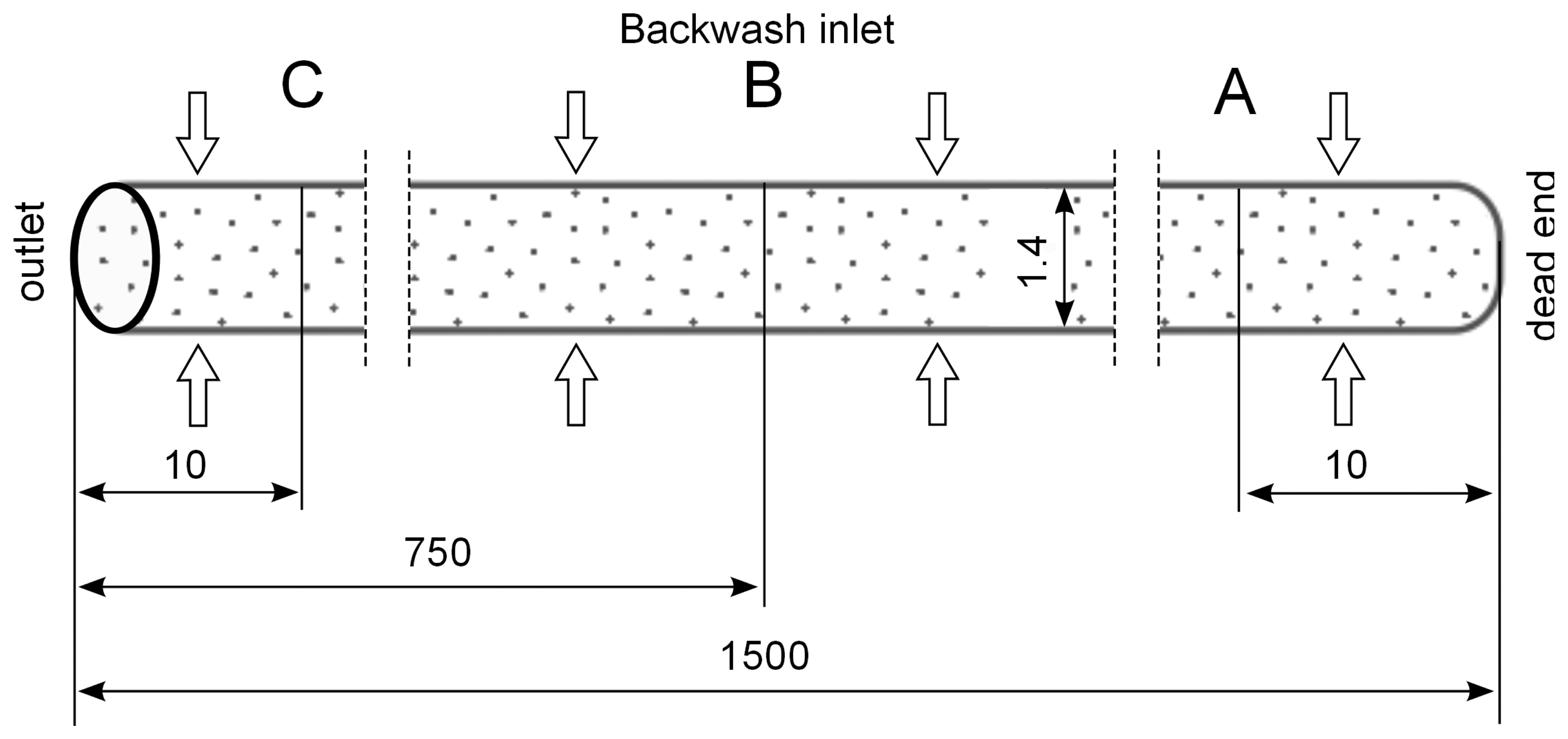
The simulation results are evaluated by inserting control lines A, B and C inside the capillary at a distance of 10 mm from the dead-end, in the middle and 10 mm from the outlet across the capillary, respectively (
Figure 2) and inserting control lines D and E at a distance of 500 μm from the axis along the capillary (
Figure 3).
A parabolic velocity profile is reached in a very short time of the simulation inside the capillary where the flow changes rapidly from radial at dead-end to axial at the outlet. The axial component of the velocity becomes dominant along the capillary compared with the radial velocity component. Due to a constant flux condition at the inlet, the flow rate increases along the membrane and the maximum value is recorded at the outlet.
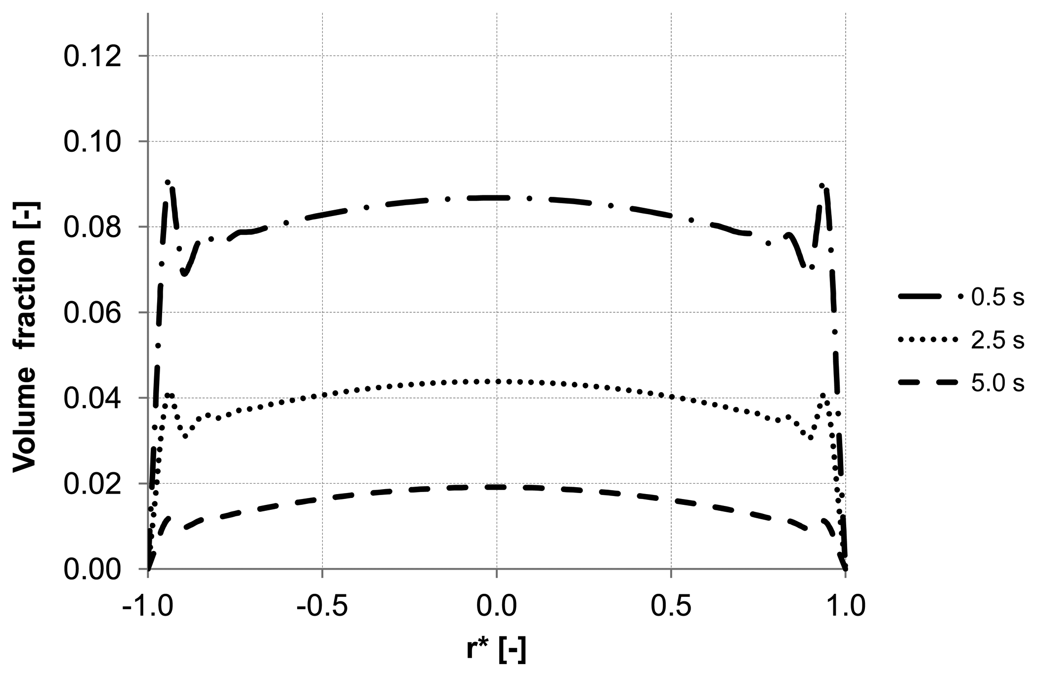
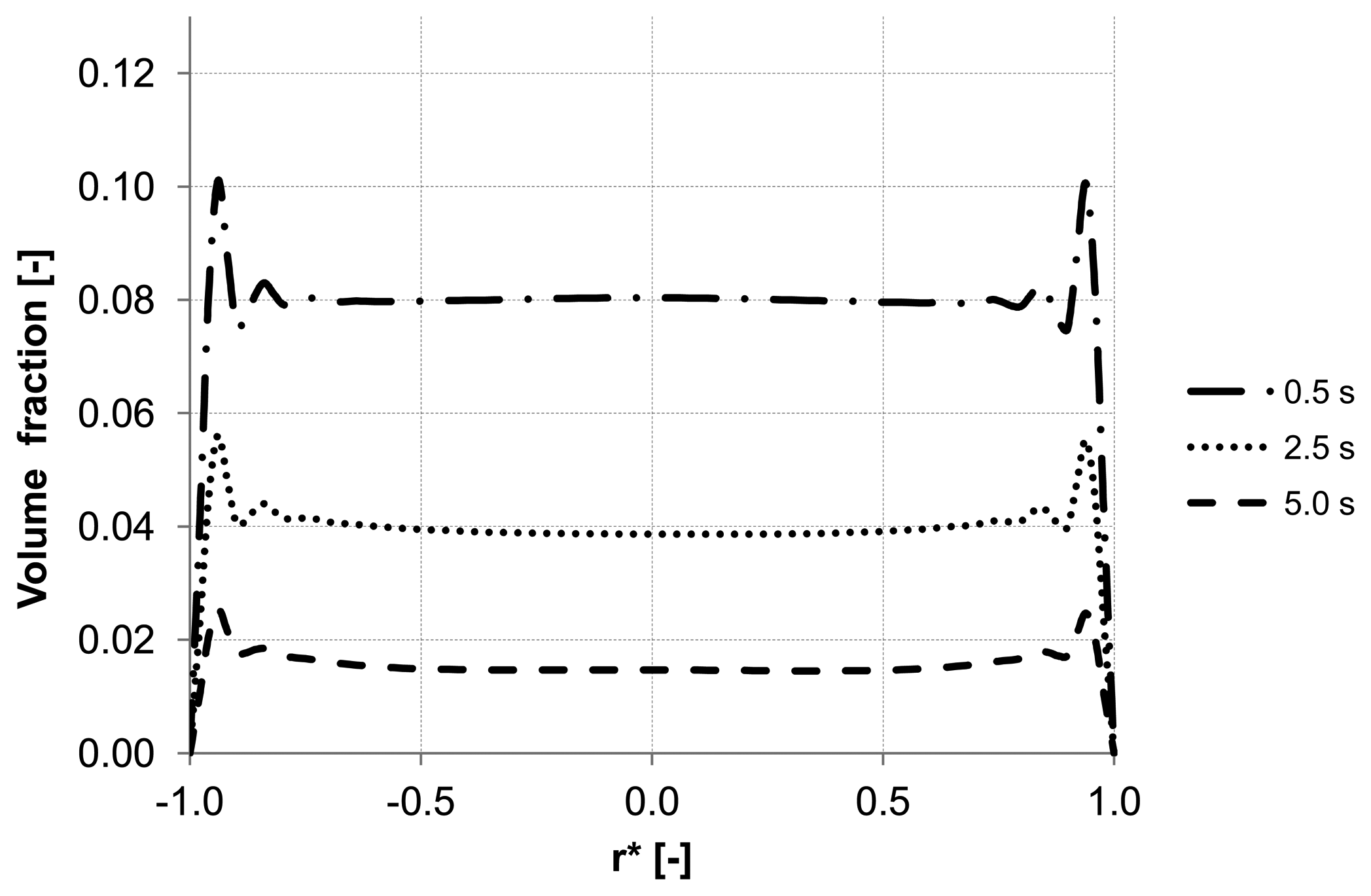
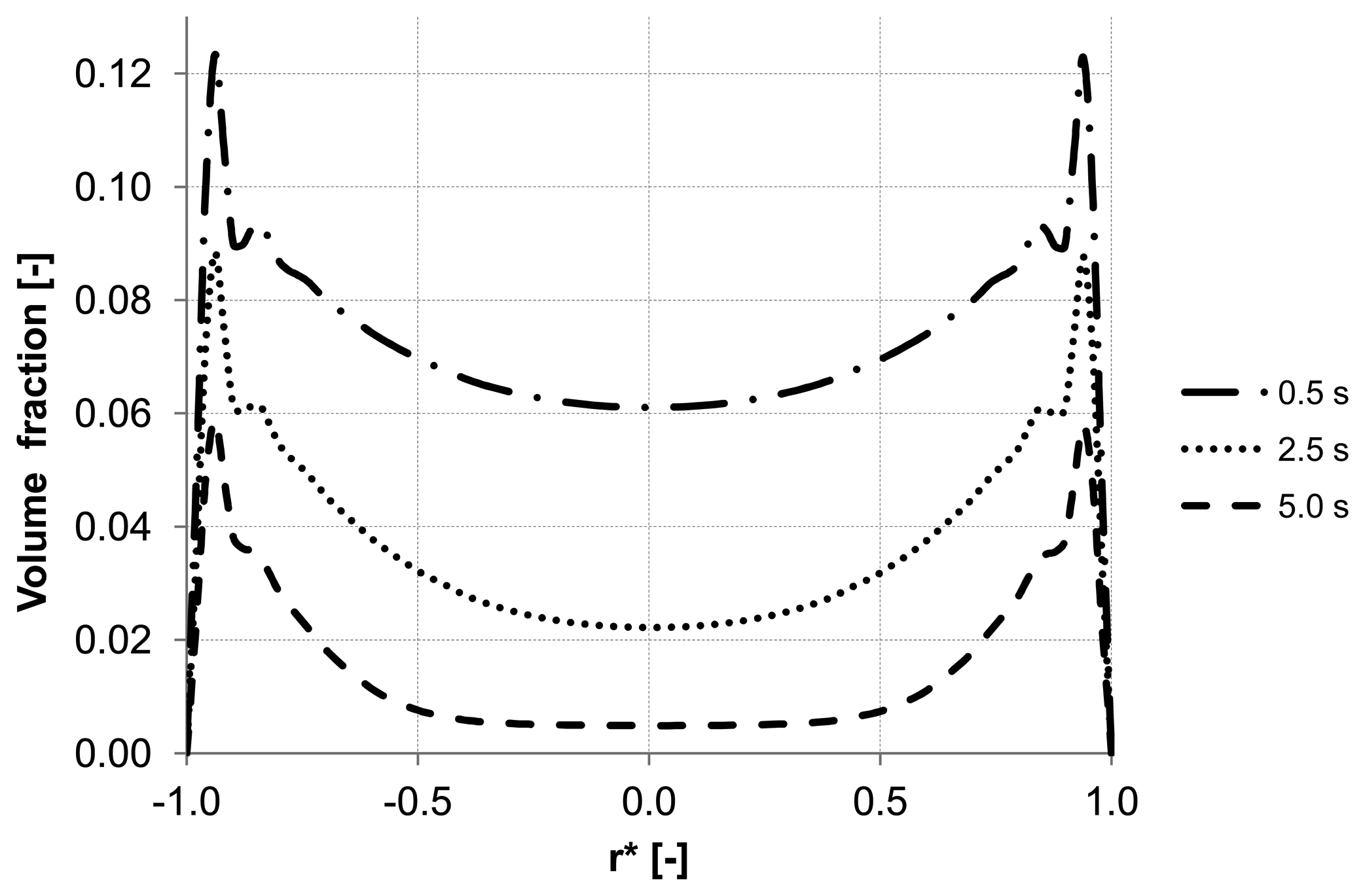
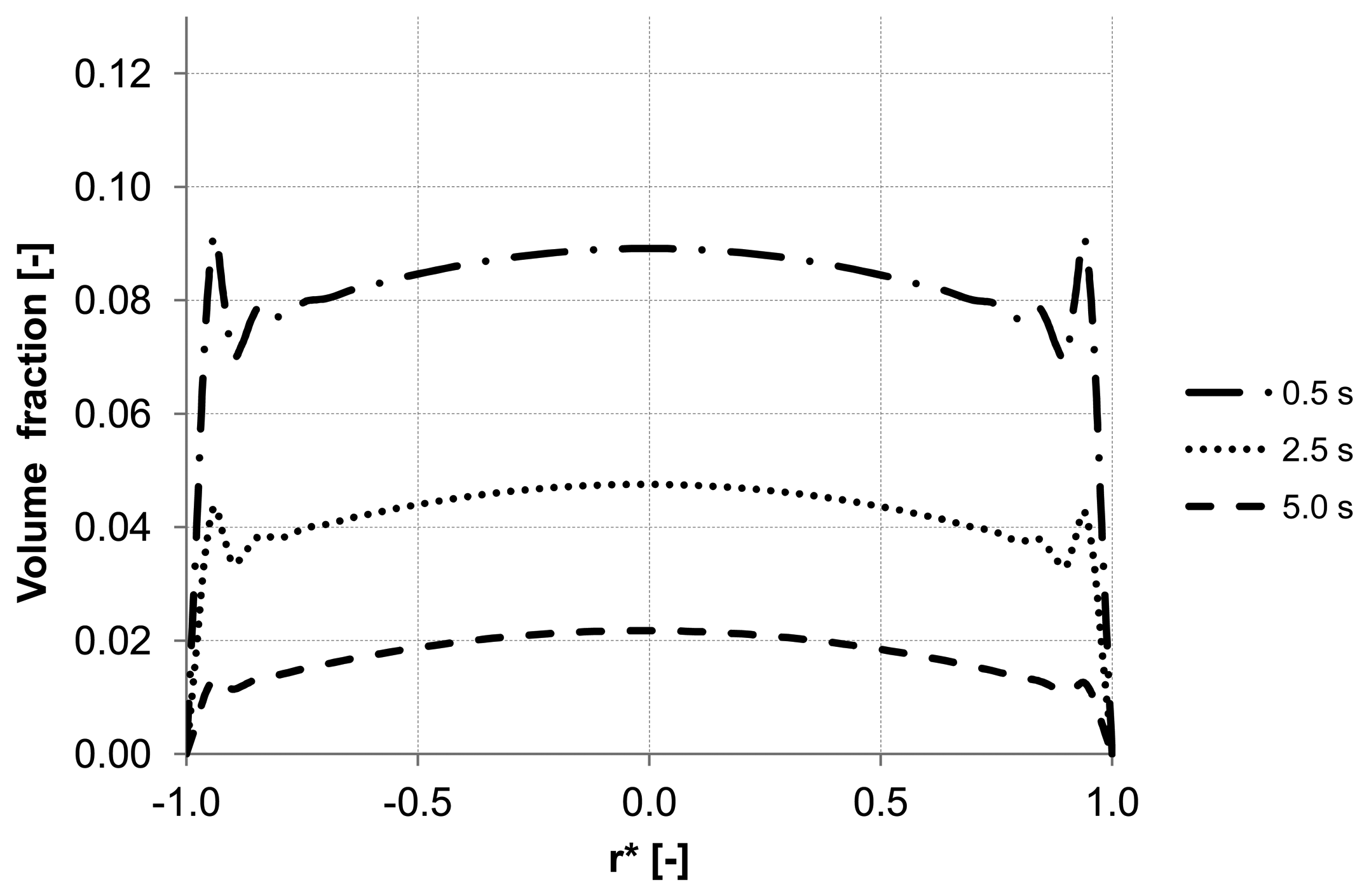
Analyzing the particle distribution along the three control lines (A, B, C) over the time as illustrated in
Figure 5,
Figure 6 and
Figure 7, a heterogeneous particle distribution inside the membrane could be observed. The particles move towards the wall where their accumulation occurs. Thus, the volume fraction increases next to the wall compared with the values around the axis and decreases over the time when the particles are flushed out of the capillary (
Figure 7). The main force responsible for the particle distribution in the membrane is the lift force. It determines the flow patterns and particle enrichment areas in the capillary. At the dead-end control line A, where a relatively small axial velocity gradient is observed the lift force is negligible as
Figure 5 shows. However, this force gets more significant with increasing the volume flow rate since the axial velocity gradient of the continuous phase becomes larger (
Figure 6). The middle control line B illustrates a lateral migration of particles depending on the Reynolds number
Re and velocity gradient.
Figure 5.
Particle distributions along control line A with backwashing flux of 300 L m−2 h−1 during 5 s (homogeneous initial distribution, particle diameter of 20 μm).
Figure 5.
Particle distributions along control line A with backwashing flux of 300 L m−2 h−1 during 5 s (homogeneous initial distribution, particle diameter of 20 μm).
Figure 6.
Particle distributions along control line B with backwashing flux of 300 L m−2 h−1 during 5 s (homogeneous initial distribution, particle diameter of 20 μm).
Figure 6.
Particle distributions along control line B with backwashing flux of 300 L m−2 h−1 during 5 s (homogeneous initial distribution, particle diameter of 20 μm).
Figure 7.
Particle distributions along control line C with backwashing flux of 300 L m−2 h−1 during 5 s (homogeneous initial distribution, particle diameter of 20 μm).
Figure 7.
Particle distributions along control line C with backwashing flux of 300 L m−2 h−1 during 5 s (homogeneous initial distribution, particle diameter of 20 μm).
To emphasize the important role of the lift force, numerical simulation of the backwash process was carried out while the lift force was not considered (
Figure 8). Comparing
Figure 7 and
Figure 8, where the particle distribution at control line C is simulated with and without lift force, respectively, a considerable difference is observed. In contrast to
Figure 8, the particles are driven towards the wall due to the effect of the lift force in
Figure 7. The distribution of the particles at control line C without lift force is similar to that distribution shown in
Figure 5 at control line A where the lift force is very small due to a small axial velocity gradient. This comparison leads to the conclusion that neglecting the lift force causes a similar distribution of the particles at all control lines (A, B, C) in the capillary.
Virtual mass force can be dropped out of the calculation since the relative acceleration between the phases is negligible due to rather small particle diameter (smaller than 20 μm) and almost similar density of both phases.
Figure 8.
Particle distributions along control line C with not considered lift force and backwashing flux 300 L m
−2 h
−1 during 5 s (
cf.
Figure 7).
Figure 8.
Particle distributions along control line C with not considered lift force and backwashing flux 300 L m
−2 h
−1 during 5 s (
cf.
Figure 7).
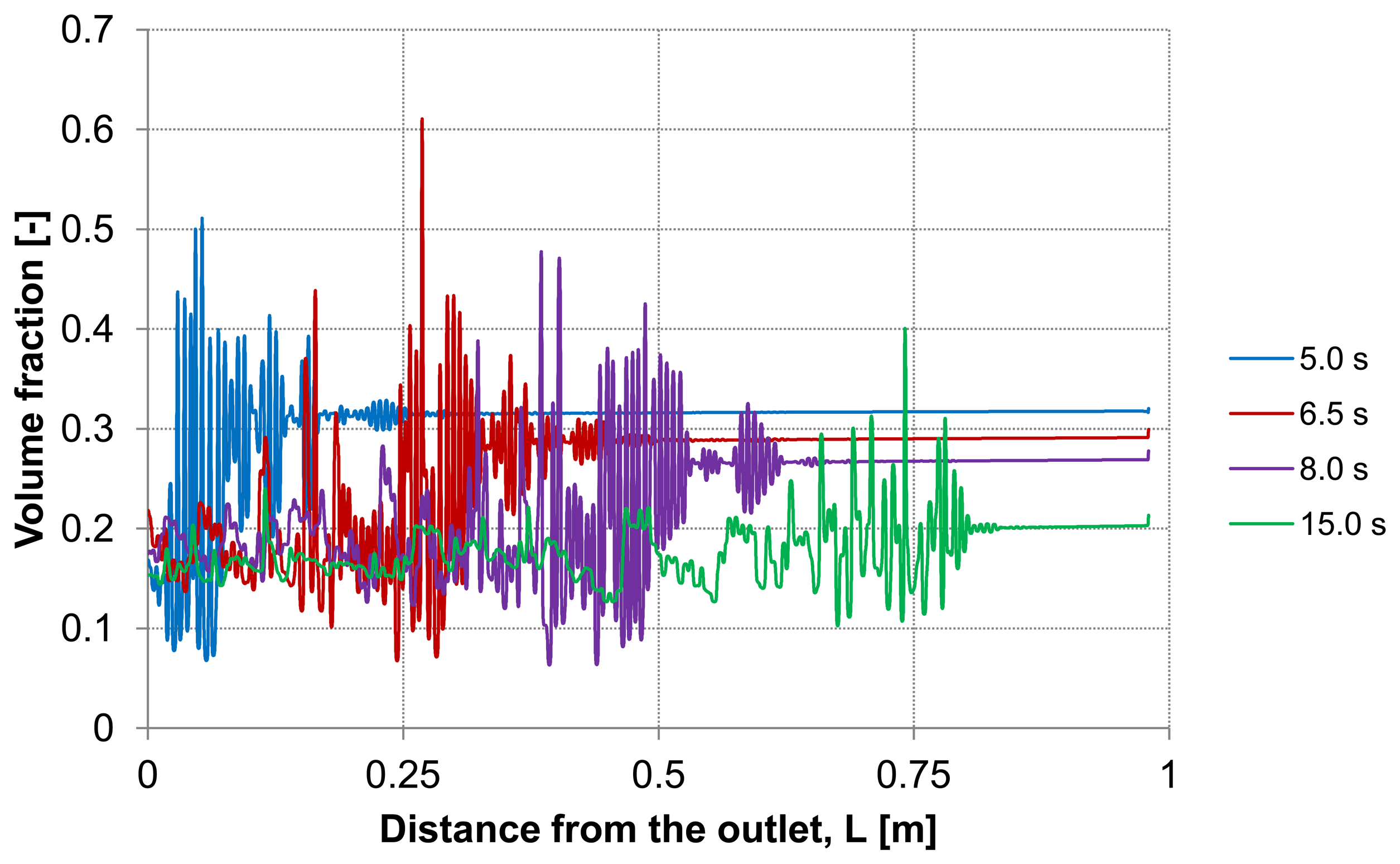
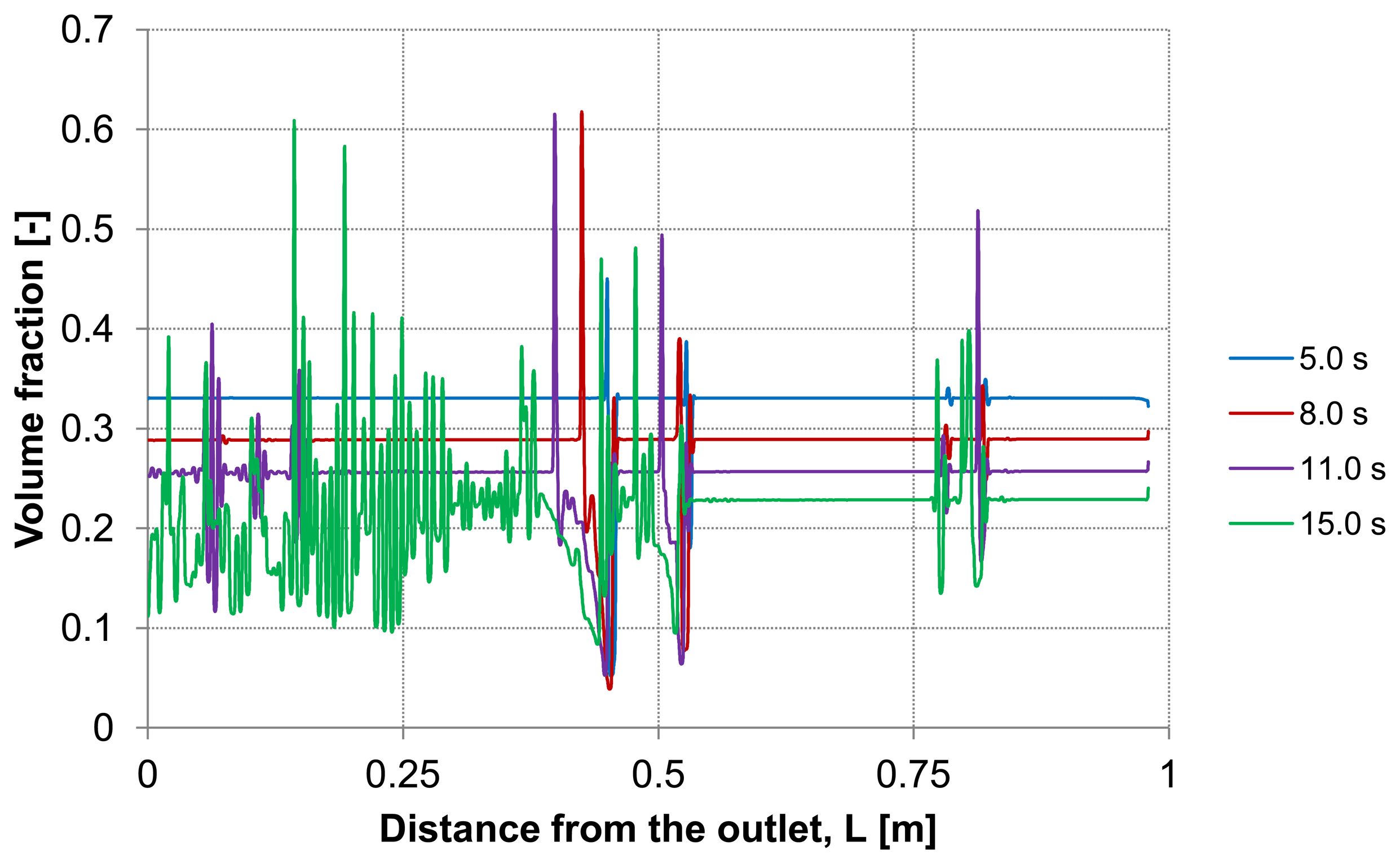
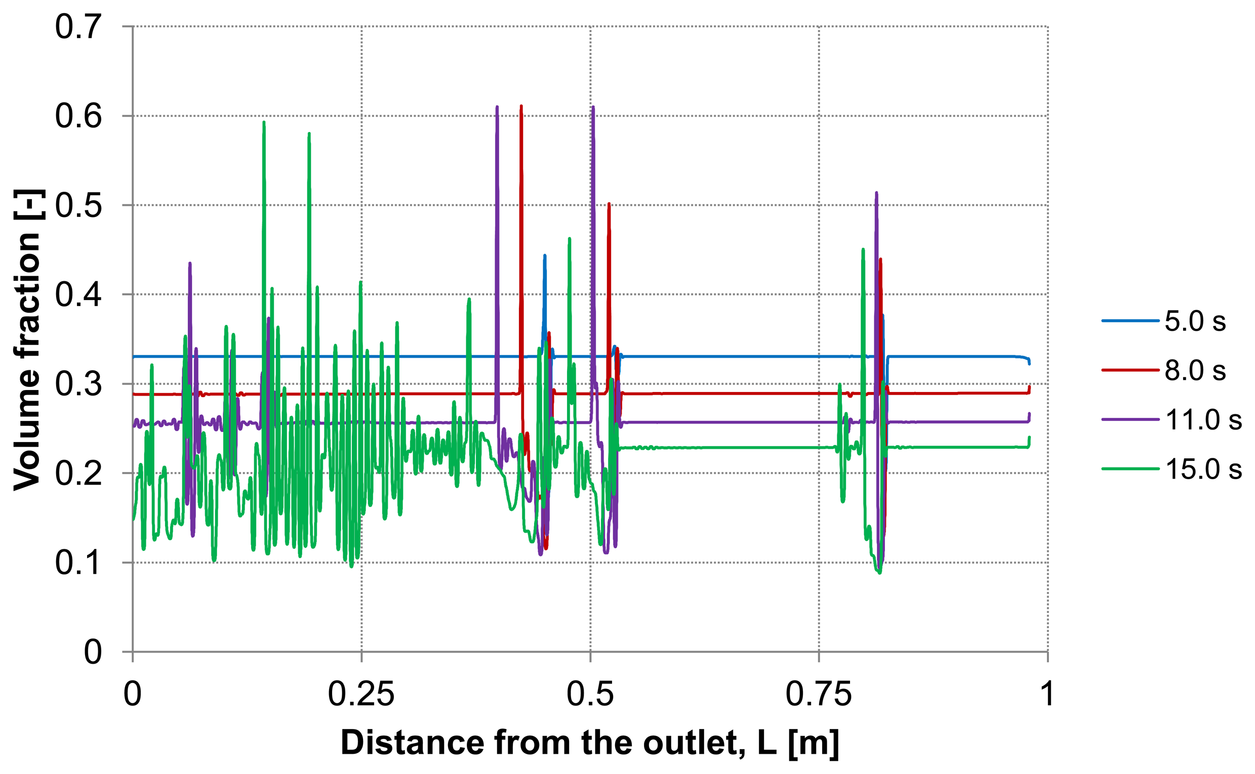
Considering the second capillary with a deposited layer,
Figure 9 and
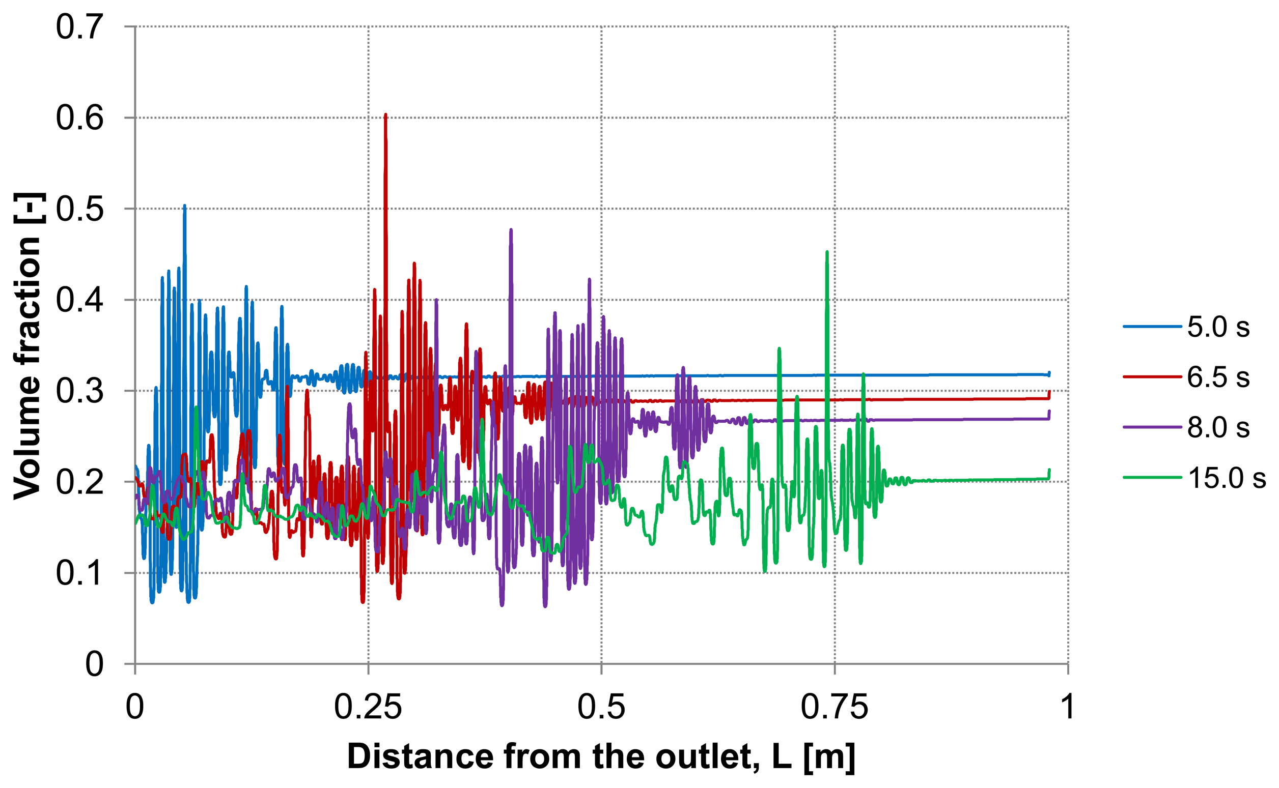
Figure 10 demonstrate the particle distribution at the control lines D and E for different backwash times ranging between 5 and 15 s. The gravity effect is pretty small due to insignificant density difference between the water and considered particles. Nevertheless, the particle distribution in lower and upper areas of the capillary shows a slight deviation from the symmetry on the control lines. As expected, a higher value of volume fraction can be seen in the lower part of the capillary. The particles behavior causes heterogeneity inside the capillary.
This heterogeneity begins next to the capillary outlet and propagates towards dead-end causing a critical increase of the particles volume fraction at certain positions. The tendency to form plugs inside the capillary has a considerable effect on backwash process. For instance, permeability, membrane resistance and energy consumption are influenced by the presence of additional obstacles.
Figure 9.
Particle distribution at control line D with backwashing flux of 300 L m−2 h−1, (deposited layer as initial distribution, particle diameter of 7 μm).
Figure 9.
Particle distribution at control line D with backwashing flux of 300 L m−2 h−1, (deposited layer as initial distribution, particle diameter of 7 μm).
Figure 10.
Particle distribution at control line E with backwashing flux of 300 L m−2 h−1, (deposited layer as initial distribution, particle diameter of 7 μm).
Figure 10.
Particle distribution at control line E with backwashing flux of 300 L m−2 h−1, (deposited layer as initial distribution, particle diameter of 7 μm).
The dilution of the detached layer depending on the distance from the outlet side for different backwash times (lines D and E in
Figure 3) are shown in
Figure 9 and
Figure 10, respectively.
At both, the upper control line D and the lower line E, consistent particles distribution is observed including some temporary peaks which refer to an enrichment of particles. The volume fraction of the particles at these peaks reaches a similar value of the initial packing density of the deposited layer. These peaks are first formed at the outlet and shifted during continuous operation of the backwash process in dead-end direction. The particle enrichment areas may lead to a probable formation of plugs inside the capillary which are accordingly moving towards dead-end.
3.1. Effect of the Particle Size
Further analysis of the backwash process was performed by considering different sizes of the suspended particles. The water flux of 300 L m−2 h−1 was constant along the inlet. Three different particle sizes were simulated 5 μm, 10 μm and 20 μm which had the same material properties.
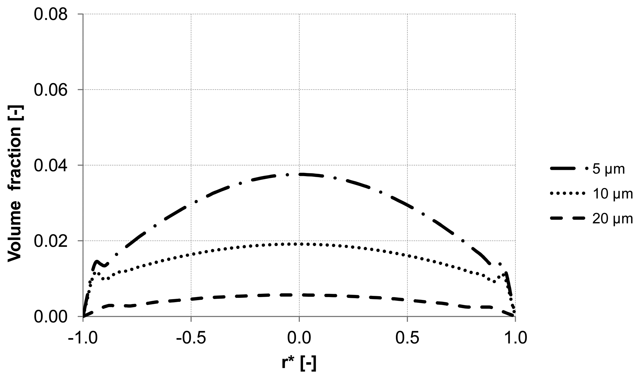
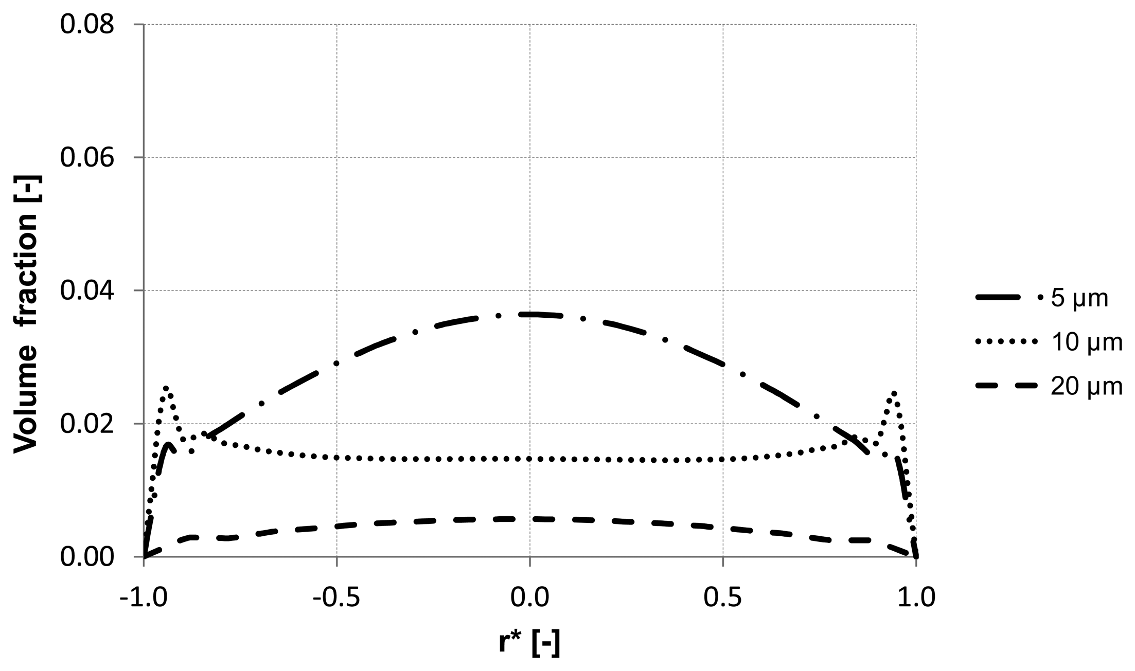
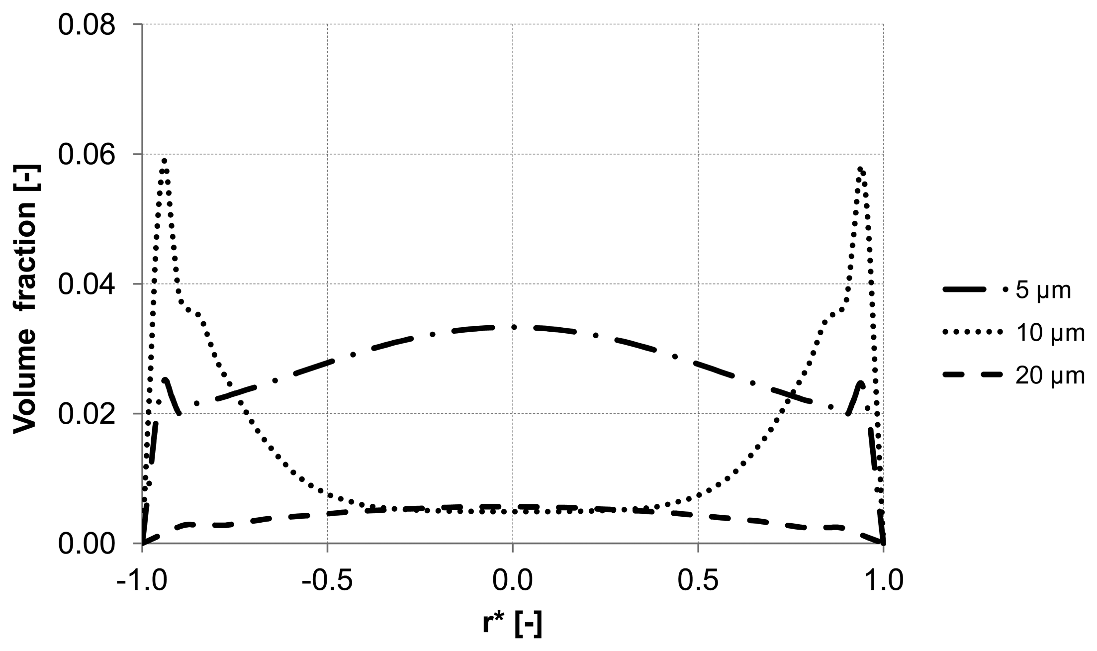
The evaluation of the particle distribution along the three control lines (A, B, C) mentioned previously at different backwash times shows different particle behavior in the membrane capillary according to the particle size. For instance, particles with a diameter of 20 μm response quickly to the continuous phase and flushed out without causing accumulation areas inside the membrane. Whereas particles with the size of 5 μm and 10 μm reveal heterogeneous particle enrichment areas in the axial region and close to the wall where accumulation areas are developed. Additionally, a significant enrichment of particles is observed close to the wall of the membrane. The distribution of the volume fraction for different particle sizes along control lines (A, B, C) is illustrated in
Figure 11,
Figure 12 and
Figure 13.
Figure 11.
Particle distribution along control line A with different particle size after 5 s (homogeneous initial distribution, backwashing flux of 300 L m−2 h−1.
Figure 11.
Particle distribution along control line A with different particle size after 5 s (homogeneous initial distribution, backwashing flux of 300 L m−2 h−1.
Figure 12.
Particle distribution along control line B with different particle size after 5 s (homogeneous initial distribution, backwashing flux of 300 L m−2 h−1.
Figure 12.
Particle distribution along control line B with different particle size after 5 s (homogeneous initial distribution, backwashing flux of 300 L m−2 h−1.
Figure 13.
Particle distribution along control line C with different particle size after 5 s (homogeneous initial distribution, backwashing flux of 300 L m−2 h−1.
Figure 13.
Particle distribution along control line C with different particle size after 5 s (homogeneous initial distribution, backwashing flux of 300 L m−2 h−1.
3.2. Effect of the Backwash Flux
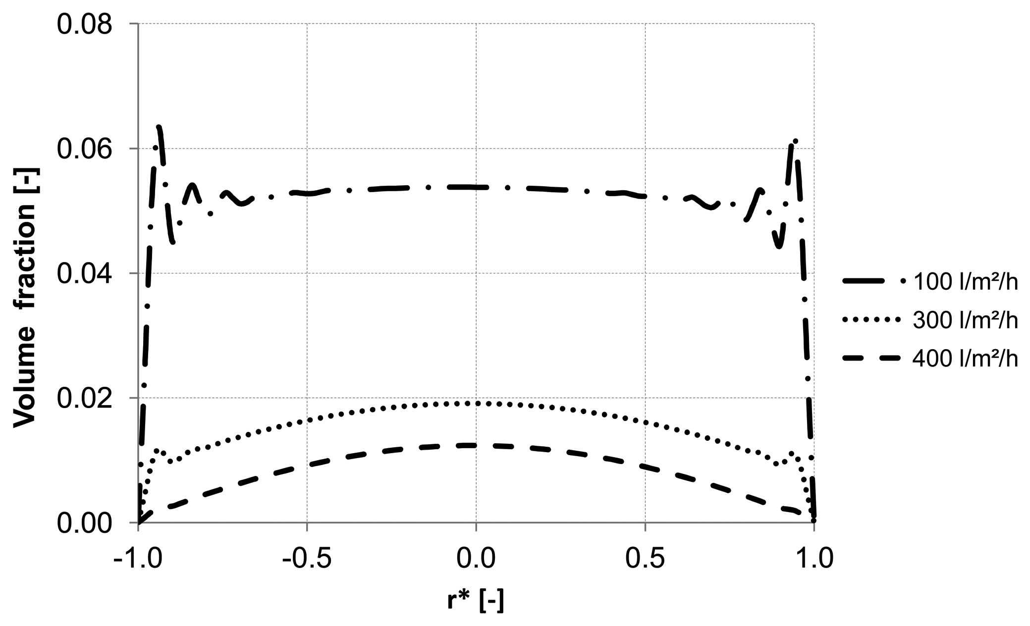
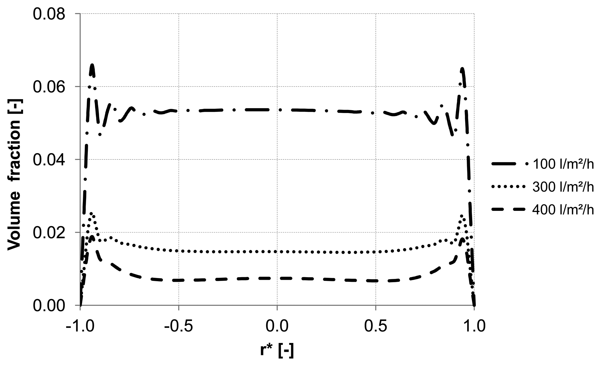
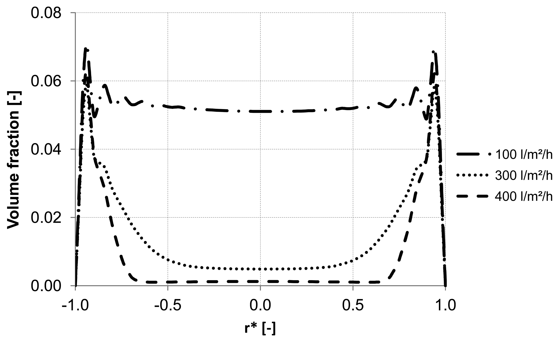
Different backwash fluxes have been investigated in order to cover a wide range of operation parameters implemented in industrial water treatment plants. An effective cleaning process is accompanied by an optimal and easy adjustable flux, which flushes off the particles and prevents the formation of plugs. Based on homogeneous particle distribution shown in
Figure 2, the effect of backwash flux was investigated while other operation conditions were kept constant. The simulation results highlight the fact that backwash flux is a significant parameter in determining the particle accumulation areas inside the membrane. The analysis of the diagrams
Figure 14,
Figure 15 and
Figure 16 at the control positions A, B and C shows a decrease of the volume fraction of particles with increasing mass flow rate. Moreover, for a flux of 100 L m
−2 h
−1 the particles are driven to the outlet without considerable lateral migration. The motion across the streamlines and the corresponding behavior of the suspended particles are caused by the relative velocity which at low Reynolds number points parallel to capillary axis. Thus, the lift force tends to drift away accumulated particles to the capillary outlet.
Figure 14.
Particle distribution along control line A with various backwashing fluxes after 8 s (homogeneous initial distribution, particle diameter of 10 μm).
Figure 14.
Particle distribution along control line A with various backwashing fluxes after 8 s (homogeneous initial distribution, particle diameter of 10 μm).
Figure 15.
Particle distribution along control line B with various backwashing fluxes after 8 s (homogeneous initial distribution, particle diameter of 10 μm).
Figure 15.
Particle distribution along control line B with various backwashing fluxes after 8 s (homogeneous initial distribution, particle diameter of 10 μm).
Figure 16.
Particle distribution along control line C with various backwashing fluxes after 8 s (homogeneous initial distribution, particle diameter of 10 μm).
Figure 16.
Particle distribution along control line C with various backwashing fluxes after 8 s (homogeneous initial distribution, particle diameter of 10 μm).
Figure 14,
Figure 15 and
Figure 16 illustrate the volume fraction of particles across the capillary at the three control lines (A, B, C in
Figure 2) over backwash time. The same figures also demonstrate a faster washing out of particles from the capillary axis when the capillary is operated with a backwash flux of 300 L m
−2 h
−1 and 400 L m
−2 h
−1.
In order to investigate the real conditions for the backwash process, initial particle distribution delivered by the experimental data (
Figure 3) was adjusted and correlated to different fluxes. The evaluation of the simulation results confirms a relatively smooth motion of the particles with less peaks and turbulent behavior inside the capillary at low flux (
Figure 17 and
Figure 18).
Figure 17.
Particle distribution at control line D with backwashing flux of 100 L m−2 h−1, (deposited layer as initial distribution).
Figure 17.
Particle distribution at control line D with backwashing flux of 100 L m−2 h−1, (deposited layer as initial distribution).
Figure 18.
Particle distribution at control line E with backwashing flux of 100 L m−2 h−1, (deposited layer as initial distribution).
Figure 18.
Particle distribution at control line E with backwashing flux of 100 L m−2 h−1, (deposited layer as initial distribution).
