Abstract
Pseudo-liquid membranes are extraction devices in which a liquid membrane phase is retained in an apparatus consisting of two interconnected chambers while feed and stripping phases pass through the stationary liquid membrane phase as mobile phases. The organic phase of the liquid membrane sequentially contacts the aqueous phases of the feed and stripping solutions in the extraction and stripping chambers, recirculating between them. This extraction separation method, called multiphase pseudo-liquid membrane extraction, can be implemented using traditional extraction equipment: extraction columns and mixer-settlers. In the first case, the three-phase extraction apparatus consists of two extraction columns connected at the top and bottom by recirculation tubes. In the second case, the three-phase apparatus consists of a recycling close-loop, which includes two mixer-settler extractors. In this study, the extraction of copper from sulfuric acid solutions in two-column three-phase extractors was experimentally studied. A 20% solution of LIX-84 in dodecane was used as the membrane phase in the experiments. It was shown that the extraction of copper from sulfuric acid solutions in the apparatuses studied was controlled by the interfacial area in the extraction chamber. The possibility of the purification of sulfuric acid wastewaters from copper using three-phase extractors is shown. To increase the degree of extraction of metal ions, it is proposed to equip two-column three-phase extractors with perforated vibrating discs. To further increase the efficiency of extraction using the pseudo-liquid membrane method, it is proposed to use multistage processes. The mathematical description of multistage three-phase pseudo-liquid membrane extraction is discussed.
1. Introduction
Bulk, supported, emulsion, and pseudo-liquid membrane separations allow two-stage separation of the components of an aqueous solution, combining the extraction and re-extraction (stripping) processes in one technological operation. In all types of liquid membranes, the separation of the components is based on their distribution between two aqueous phases through an organic transfer medium (liquid membrane). One of the simplest types of liquid membranes is the bulk liquid membrane [1,2,3,4,5,6,7,8,9], but its disadvantage—low mass transfer efficiency caused by small interfacial area per unit volume—makes it unpromising for large-scale industrial applications. In supported liquid membranes [10,11,12,13,14,15,16,17,18,19], two aqueous phases (feed and stripping phases) flow on opposite sides of the porous support in the small pores of which the liquid membrane is retained. In the emulsion liquid membrane technique [20,21,22,23,24,25,26,27,28,29,30,31,32,33,34], complex water-in-oil emulsions are used: the first aqueous (stripping) phase is encapsulated in the form of microdroplets in the organic membrane; large droplets fall or rise in the continuous second aqueous phase (the feed solution or raffinate phase). In pseudo-liquid membrane separation, the process is carried out in a three-phase mass transfer stage (extraction apparatus), consisting of two interconnected contact chambers in which the membrane phase contacts the feed and stripping phases and recirculates inside the stage, forming a closed circuit [35,36].
Compared to traditional liquid extraction, the main advantages of liquid membrane separation are significant savings in reagents and solvents, as well as better separation of mixture components, especially when processing dilute solutions. In addition, liquid membrane methods are more environmentally friendly since the organic phase is not removed from the process unit. Therefore, liquid membrane methods can be used to separate and concentrate metal ions from dilute aqueous solutions when solvent extraction processes cannot be effectively applied. Due to the low productivity and complexity of the equipment, traditional methods of liquid membrane separation have not yet found wide industrial applications. Since the currently available liquid membrane equipment cannot process large volumes of dilute solutions, we previously [37,38,39,40,41,42,43,44,45] proposed the use of solvent extraction equipment as a large-scale device for bulk liquid membrane separation processes. This bulk liquid membrane separation method based on the extraction equipment has been called three- and multiphase extraction or pseudo-liquid membrane multiphase extraction [46]. It may also be referred to as pseudo-liquid membrane technology. This name (more precisely, electrostatic pseudo-liquid membranes) was apparently first introduced by Chinese researchers [35,36] to designate a device filled with a non-polar transport medium through which two dispersed aqueous phases are passed: the feed solution containing metal ions and the receiver phase. Drops of both aqueous phases break up into smaller droplets under the influence of a high-voltage electrostatic field; flows of dispersed phases are separated by a partition [47,48]. With the help of strong electrostatic fields, it is possible either to separate water droplets from the organic phase by electrocoalescence or to deform and break the droplets into smaller ones. The work of [49] presents the results of an experimental investigation of drop break-up in different liquid–liquid systems. In [47], the separation of nickel and cobalt in an electrostatic pseudo-liquid membrane apparatus was investigated using a pregnant leach solution as a feed solution. The effects of operating parameters, such as feed and strip flow rates, pH, and applied voltage, have been studied. In [50], electrospun hybrid membranes were applied to remove heavy metals and produce ultra-pure water. It was established that the introduction of a condensed Ti-O-Ti structure into the membranes significantly increased the performance but did not improve the permeate flux of the membranes. Asymmetric thermal treatment of the membranes resulted in an increase in the permeate flux without affecting the separation.
In the processes of pseudo-liquid membrane separation and extraction separation, first, one of the phases (light or heavy) is dispersed in the form of droplets in the second phase due to intensive mixing, and then droplet coalescence and gravitational phase separation occur (Figure 1).
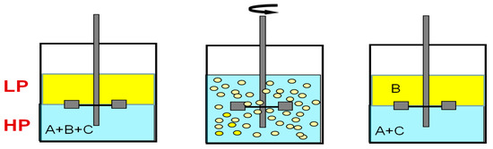
Figure 1.
General scheme of extraction processes. A–C—components of the mixture.
Solvent extraction technologies use mixer-settlers and column extractors to carry out these processes. Mixer-settler extractors are widely used in hydrometallurgy to separate metal compounds, including rare earth elements. A mixer-settler extractor consists of two chambers: a mixing chamber, where the organic and aqueous phases are mixed to form an emulsion, and a separation chamber (settler), where the emulsion is separated. Figure 2 is a diagram of the connection of two mixer-settlers operating in pseudo-liquid membrane mode. The organic membrane phase circulates between the extractors, sequentially contacting the aqueous phases of the feed and stripping solutions in the extraction and stripping apparatuses. In such a system, the membrane phase can be either dispersed or continuous in the mixing chambers of the extractors.
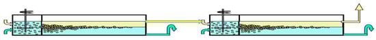
Figure 2.
Two mixer-settlers operating in pseudo-liquid membrane mode.
Column extractors are used in the chemical industry for the separation and purification of organic and inorganic compounds from process solutions and industrial wastewater treatment. These apparatuses can be divided into two groups: (1) columns with an external energy input, in which kinetic energy is supplied with agitators of various types for dispersion of one of the phases (dispersed) in the volume of the other (continuous) and (2) columns without energy input. In the apparatuses of the first group, sufficient interfacial area is provided, and interphase mass transfer is enhanced by the energy supply.
Similar to the combination of two mixer-settlers, two columns (for extraction and stripping) can be connected at the top and bottom, with overflows for circulation of the membrane phase to create a two-chamber three-phase extractor operating in pseudo-liquid membrane mode. In such a system, for convective circulation of the membrane phase, this phase should be continuous in the columns of the three-phase extractor. Convective circulation of the membrane phase between the extraction and stripping columns can be organized due to the difference in the weight of the emulsion in the columns through which the dispersed aqueous feed and stripping phases pass.
Multistage processes are commonly used to enhance extraction separation processes. The mathematical models of various schemes of multistage pseudo-liquid membrane extraction were developed in our previous studies [39,40,46,51,52,53]. The theoretical model of multistage two-column pseudo-liquid membrane extraction with countercurrent flows of phases in extraction and stripping columns is shown in Figure 3. To simulate such extraction separations, the following equations can be used:
where and are dimensionless parameters (extraction and stripping factors); and are dimensionless parameters characterizing the mass transfer rate in extraction and stripping columns, known as the numbers of transfer units; L1 and L2 are the column lengths; and are the concentrations of a solute in the feed and in the raffinate; and are specific phase contact surfaces in the extraction and stripping columns; and are mass-transfer coefficients at the extraction and stripping steps, respectively; and are specific flow rates of the feed and raffinate phases; w is the specific flow rate (circulation rate) of the membrane phase; and and are the concentrations in the feed and raffinate phases (symbol * denotes equilibrium conditions).
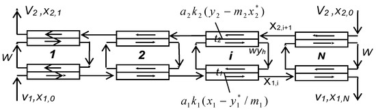
Figure 3.
Schematic diagram of multistage three-phase extraction processes.
Equations (1)–(4) are based on the assumptions that equilibrium-distribution coefficients and are constant and that the phases in the extraction and stripping columns move countercurrently and in the plug-flow mode. When the pseudo-liquid membrane multistage extraction processes are carried out in a cascade of mixer-settler extractors, equilibrium distribution of the passing components is achieved in the extraction and stripping chambers, and they represent theoretical stages (t1→∞, t2→∞). The concentration in the raffinate in these processes can be calculated using the following equation:
As the rate of membrane phase circulation between the extraction and stripping steps rises (w→∞), the concentration ratio in the phases in the extraction and stripping apparatuses approaches an equilibrium value equal to m1/m2, and Equation (5) reduces to
with
In conventional countercurrent extraction in a cascade of N equilibrium stages, the concentration in the raffinate is determined by Equation (8):
where
- is the extraction factor; .
From Equations (6) and (8), the conclusion can be drawn that Equation (6) determines the efficiency of the pseudo-liquid membrane multistage extraction carried out in a cascade of N theoretical two-chamber mass-transfer stages.
In our recently published work [37], we presented the results of an experimental study of the extraction of phenol from sulfuric acid solutions in two-column pseudo-liquid membrane apparatuses using butyl acetate as an organic membrane phase and a 5–12% NaOH aqueous solution as a stripping phase. It was shown that the devices under consideration can be successfully used for wastewater treatment from phenol and multiple concentrations of phenolate in the stripping phase, which can be achieved due to the recirculation of this phase. Earlier, in [38], the possibility of successful separation of uranyl, ytterbium, and lanthanum nitrates in a three-column multiphase extractor was established.
In this work, the results of an experimental study of the extraction of copper in two-column pseudo-liquid membrane extractors are presented. The purpose of the copper extraction experiments was to study the possibility of the purification of sulfuric acid wastewaters generated in the production of non-ferrous metals and in the processing of products from copper using two-column pseudo-liquid membrane extractors.
2. Materials and Methods
2.1. Reagents
The following reagents were used in this study: copper(II) sulfate pentahydrate (98%, CAS no. 7758-99-8, Sigma-Aldrich, St. Louis, MO, USA), LIX-84 (BASF, Indonesia), dodecane (CAS no. 13475-82-6, Acros Organics, Germany), decane (99+%, pure, CAS no. 124-18-5, Acros Organics, Germany), n-undecane (99%, CAS no. 1120-21-4, Acros Organics, Germany), and sulfuric acid (chemically pure, Khimreaktivsnab, Russia).
2.2. Apparatuses
As mentioned above, a pseudo-liquid membrane device is a three-phase extractor comprising an extraction column and a stripping column, each of which consists of contacting and separation zones; the columns are connected by overflows for circulation of a continuous membrane phase. In the extraction column, the feed solution is brought into contact with the membrane phase, from which the extracted compounds are stripped in the second column with a stripping phase. The feed solution and the stripping phase are each dispersed into droplets in the appropriate column by means of dispersing devices. Owing to the difference in density between the emulsions in the first and second columns, circulation of the continuous phase, which is the extractant phase, occurs through the upper and lower overflows, resulting in transfer of the substances to be extracted from one column to the other and from the first dispersed phase into the second.
For experimental studies, two two-column glass apparatuses were designed and manufactured: (1) a small one: columns with a diameter of 30 mm and a height of 400 mm in which the columns are connected by overflow pipes and equipped with bottom settlers and upper separating zones (Figure 4); and (2) a large two-column extractor whose columns have a diameter of 80 mm and a height 900 mm; the columns are connected at the bottom (by a horizontal cylindrical settler 80 mm in diameter) and at the top (by a separator of a similar design) (Figure 5). For the dispersion of aqueous phases in the columns, fluoroplastic distributors with different hole diameters were used.
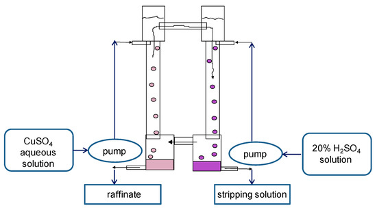
Figure 4.
Scheme of the experimental setup of the small two-column extraction apparatus. Columns have a diameter of 30 mm and a height of 400 mm. To extract copper from sulfuric acid solution, a 20% solution of LIX-84 in dodecane was used as an organic membrane phase, and a 20% solution of sulfuric acid was used as a stripping phase.
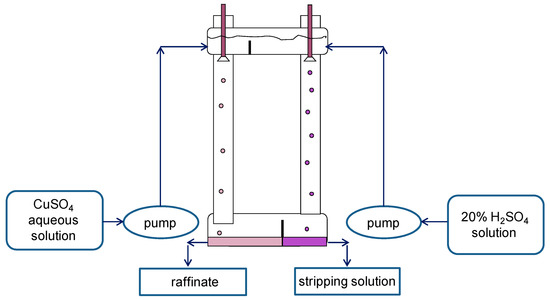
Figure 5.
Scheme of the experimental setup of the large two-column extractor. Columns have a diameter of 80 mm and a height of 900 mm. To extract copper from sulfuric acid solution, 20% LIX-84 was used as an organic phase in a mixture containing 42% dodecane, 31% decane, and 27% undecane, and a 20% solution of sulfuric acid was used as a stripping phase.
2.3. Feed Solutions and Extraction Systems
To extract copper from sulfuric acid solutions, the 20% solution of LIX-84 in dodecane was used as the organic membrane and the 20% sulfuric acid solution as the stripping phase. The concentration of copper was determined in aqueous solution—by the photometric method in the form of an ammonia complex—and in the organic phase—from the difference between the concentrations in the feed solution and in the aqueous phase after extraction.
3. Results and Discussion
The equilibrium distribution of copper from sulfuric acid solution in the system with 20% LIX-84 in decane was preliminarily studied. The initial aqueous solution contained 1225 ppm CuSO4. In the experiments, the ratio of the aqueous and organic phases varied. The data obtained are presented in Table 1.

Table 1.
Results of copper extraction and stripping in the system with 20% LIX-84 in decane (equilibrium data).
The results of the experiments on apparatus 1 are shown in Table 2. As can be seen from the data in Table 2, when using distributors with smaller diameter holes, the extraction of copper increases. In these experiments, the cocurrent flow of the phases in the extraction column and the countercurrent flow of the aqueous and organic phases in the stripping column were observed.
Table 2.
Results and conditions of experiments conducted in the small apparatus.
In experiments on the large three-phase extractor, 20% LIX-84 was used as the organic phase in a mixture containing 42% dodecane, 31% decane, and 27% undecane. Two series of experiments were carried out in this apparatus. In the first series, as in apparatus 1, the crushing of aqueous phases was carried out using an inlet dispersing device (distributor). The results of this series of experiments are shown in Table 3, from which it follows that the extraction of copper increased slightly due to the increase in the height of the columns. The low efficiency of the apparatuses is due to the fact that the dispersing devices do not provide a sufficiently large phase contact surface (large droplets are formed during crushing by distributors). Distributors located at the top of the columns allowed only a single crushing of the aqueous phases, while agitators provided more intensive multiple crushing with the formation of small droplets.
Table 3.
Results and conditions of experiments conducted in the large apparatus.
To intensify dispersion in subsequent experiments, nine perforated discs (sieve plates) made of PTFE were placed in the extraction column. The discs were mounted on a vertical rod connected to a vibration drive. The discs were given high-frequency oscillations (50 sec−1) with an amplitude of 1 mm. As follows from Table 4, the efficiency of the process increased dramatically.
Table 4.
Results of experiments conducted in apparatus 2 when vibrating sieve plates were placed in the extraction column.
In experiments 4 and 5, the oscillation amplitude was increased by 20%, which decreased the copper concentration in the raffinate by another order of magnitude. We can conclude that the interphase surface in the extraction column determines the efficiency of copper extraction from sulfuric acid solutions in the two-column extractor. It is known that the mass transfer rate in extraction is proportional to the interfacial area per unit volume of the contacting phases. In addition, the extraction of metal ions is usually associated with a chemical reaction at the phase interface. Therefore, an increase in the phase contact surface leads to an intensification of the metal extraction processes.
The rate of extraction processes in two-column three-phase extraction apparatuses is determined by the rate of mass transfer, the flow regime in the extraction and stripping columns, and the circulation rate of the membrane phase between the columns. With an increase in the rate of mass transfer in the columns and the rate of circulation of the membrane phase between them, the efficiency of three-phase extraction increased. The rate of mass transfer in the columns can be significantly increased by equipping them with vibrating sieve plates. In two-column extractors with convective circulation of the membrane phase, two flow designs, namely cocurrent flows of phases in the extraction column and countercurrent flows of the phases in the stripping column, and vice versa, are possible. For the most efficient extraction separation, the flow directions of the aqueous feed and stripping solutions should be opposite the direction of the membrane phase flow in the extraction and stripping columns. The circulation rate of the membrane phase in a two-column extraction apparatus with convective circulation of the membrane phase is influenced by its configuration (the design of the overflows and the height of the columns). Through the forced circulation of the membrane phase, countercurrent flows of phases can be established in both columns. To organize the countercurrent mode simultaneously in the extraction and stripping columns and to increase the interphase surface, the apparatus shown in Figure 6 is equipped with perforated vibrating discs placed in the extraction column and packing placed in the stripping column. During operation of the vibratory mixer (perforated discs), the aqueous feed phase was crushed into small droplets, and the continuous organic membrane phase was pumped (the direction of circulation is shown by arrows) in the system.
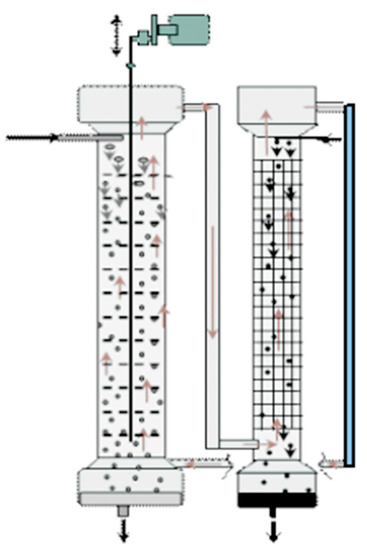
Figure 6.
Schematic principles of the operation of the two-column three-phase extraction apparatus with forced circulation of the membrane phase and countercurrent flows of phases in both columns. Red arrows—circulation of the membrane phase; black arrows—flows of the aqueous phases.
An increase in the degree of extraction of metals in two-column three-phase extraction can be achieved using multistage processes that carry out the separation in a cascade of two-column extractors (Figure 7) or in multistage two-chamber columns (Figure 8). In the case when the mass transfer in the stripping column is associated with an irreversible chemical reaction, the efficiency of the separation process is determined by the mass transfer in the extraction column, and it is possible to concentrate the extractable metal in the stripping phase by recycling this phase at the stripping stage. Figure 7 shows an example of such a multistage three-phase extraction separation with recirculation of the stripping phase at each stage.
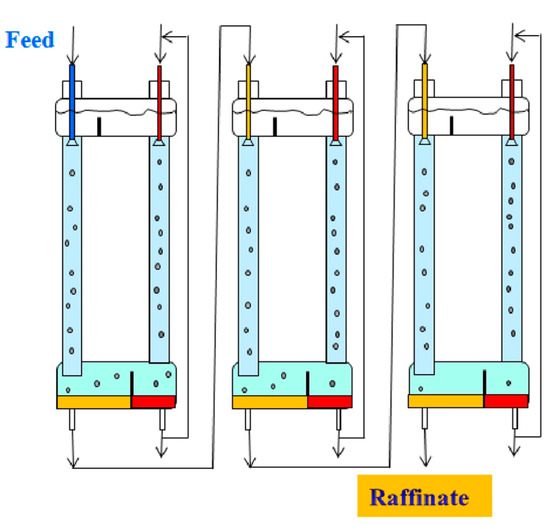
Figure 7.
The process of multistage three-phase extraction separation in a cascade of two-column three-phase apparatuses with recirculation of the stripping phase at each stage.
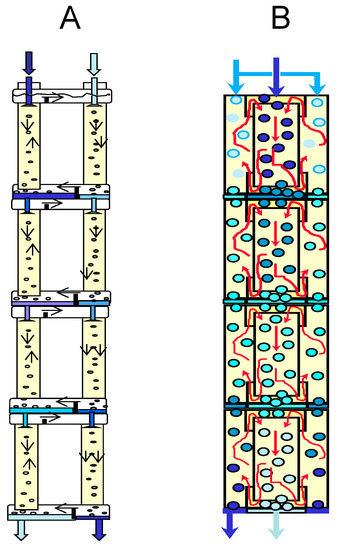
Figure 8.
Multistage three-phase extraction apparatus, consisting of two-column stages (A) and a multistage two-chamber extraction column (B).
Figure 8 shows some possible options for a multistage three-phase two-chamber extraction column.
The multistage three-phase extraction separations with the countercurrent flows of phases in extraction and stripping columns can be simulated by Equations (1)–(4). For other phase flow regimes in the extraction and stripping columns, the concentration in the raffinate can be calculated by Equations (1) and (2) using the following Equations for S1 and S2 parameters:
Cocurrent flow of the aqueous and organic phases in the extraction column and countercurrent flow of the phases in the stripping column:
Cocurrent flow of the aqueous and organic phases in the stripping column and countercurrent flow of the phases in the extraction column:
It should be noted that multistage three-phase extraction is actually a staged version of a supported liquid membrane.
For single-stage apparatuses, Equation (1) reduces to:
Equation (13) can be used to simulate single-stage three-phase extraction processes and evaluate the influence of the operating parameters on separation efficiency.
The limitations of this study are: (1) The experiments were conducted in three-phase extractors with convective circulation of the membrane phase, which allows two options: countercurrent flow of the contacting phases in the extraction and cocurrent flow of the phases in the stripping columns, and vice versa; and (2) the rate of mass transfer in the extraction and stripping columns was not quantitatively determined, since the rate of circulation of the membrane phase between them was not measured. For further development and industrial implementation of three-phase extraction technology in hydrometallurgy, more detailed studies are needed using single-stage and multistage apparatuses of various designs, including those with forced circulation of the membrane phase. Using single-stage apparatuses, it is possible to evaluate the mass transfer rate in the extraction and stripping stages and determine the influence of the main operating parameters on it. In these experiments, by measuring the circulation rate of the membrane phase, it is possible to determine the rate of mass transfer in the extraction and stripping chambers using Equation (13).
4. Conclusions
In this study, the extraction of copper in two-column three-phase extractors with countercurrent flow of contacting phases in the extraction columns and cocurrent flow of phases in the stripping columns was experimentally studied. The 20% solution of LIX-84 in dodecane was used as the organic membrane phase for extracting copper from sulfuric acid solutions. It was shown that the interface area in the extraction column determined the efficiency of copper extraction from sulfuric acid solutions in the apparatuses studied.
The studied devices can be used for wastewater treatment from copper and other harmful impurities. To promote the countercurrent mode simultaneously in the extraction and stripping columns and to increase the degree of extraction of metal ions, it is proposed to equip two-column three-phase extractors with perforated vibrating discs. Multistage processes can be used to further improve the extraction efficiency of the pseudo-liquid membrane method. Mathematical modeling of multistage pseudo-liquid membrane extraction processes was discussed.
Author Contributions
Conceptualization, A.E.K.; Methodology, A.E.K. and V.V.B.; Validation, A.A.V. and Y.A.Z.; Formal Analysis, A.E.K., A.A.V. and V.V.B.; Writing, Review, and Editing, A.E.K. and V.V.B.; Visualization, V.V.B. and Y.A.Z.; Project Administration, A.A.V. All authors have read and agreed to the published version of the manuscript.
Funding
This work was supported by the Ministry of Science and Higher Education of the Russian Federation as part of the State Assignment of the Kurnakov Institute of General and Inorganic Chemistry of the Russian Academy of Sciences.
Institutional Review Board Statement
Not applicable.
Data Availability Statement
Not applicable.
Conflicts of Interest
The authors declare no conflict of interest.
Nomenclature
, —interfacial area per unit volume of contacting phases in the extraction and stripping columns; , —extraction and stripping factors; , —mass transfer coefficients at the extraction and stripping steps, respectively; L1, L2—columns lengths; , —dimensionless parameters characterizing the mass transfer rate in the extraction and stripping columns (the numbers of transfer units); , —specific flow rates of the feed and raffinate phases; w—specific flow rate (circulation rate) of the membrane phase; , —concentrations of a solute in the feed and in the raffinate.
References
- Albu, P.C.; Tanczos, S.-K.; Ferencz (Dinu), A.; Pîrtac, A.; Grosu, A.R.; Pascu, D.; Grosu, V.-A.; Bungău, C.; Nechifor, A.C. pH and design on n–alkyl alcohol bulk liquid membranes for improving phenol derivative transport and separation. Membranes 2022, 12, 365. [Google Scholar] [CrossRef] [PubMed]
- Ferencz (Dinu), A.; Grosu, A.R.; Al-Ani, H.N.A.; Nechifor, A.C.; Tanczos, S.-K.; Albu, P.C.; Crăciun, M.E.; Ioan, M.-R.; Grosu, V.-A.; Nechifor, G. Operational limits of the bulk hybrid liquid membranes based on dispersion systems. Membranes 2022, 12, 190. [Google Scholar] [CrossRef] [PubMed]
- Aldwaish, M.; Kouki, N.; Algreiby, A.; Tar, H.; Tayeb, R.; Hafiane, A. An Ionic supported liquid membrane for the recovery of bisphenol A from aqueous solution. Membranes 2022, 12, 869. [Google Scholar] [CrossRef] [PubMed]
- Chang, S.H. Types of bulk liquid membrane and its membrane resistance in heavy metal removal and recovery from wastewater. Desalination Water Treat. 2016, 57, 19785–19793. [Google Scholar] [CrossRef]
- Wang, B.-Y.; Zhang, N.; Li, Z.-Y.; Lang, Q.-L.; Yan, B.-H.; Liu, Y.; Zhang, Y. Selective separation of acetic and hexanoic acids across polymer inclusion membrane with ionic liquids as carrier. Int. J. Mol. Sci. 2019, 20, 3915. [Google Scholar] [CrossRef] [PubMed]
- Nezhadali, A.; Es’haghi, Z.; Bahar, S.; Banaei, A.; Shiran, J.A. Selective separation of silver(I) ion through a bulk liquid membrane containing 1,1’-(1,3-phenylene)bis(3-allylthiourea) as carrier. J. Braz. Chem. Soc. 2016, 27, 99–108. [Google Scholar] [CrossRef]
- Khalaf, Z.A.; Hassan, A.A. Studying of the effect of many parameters on a bulk liquid membrane and its opposition in Cd(II) removal from wastewater. J. Phys. Conf. Ser. 2021, 1973, 012097. [Google Scholar] [CrossRef]
- Ramkumar, J.; Chandramouleeswaran, S. A perceptive on bulk liquid membrane: A brief review. Indian J. Adv. Chem. Sci. 2015, 3, 293–298. [Google Scholar]
- Singh, R.; Mehta, R.; Kumar, V. Simultaneous removal of copper, nickel and zinc metal ions using bulk liquid membrane system. Desalination 2011, 272, 170–173. [Google Scholar] [CrossRef]
- Alemrajabi, M.; Ricknell, J.; Samak, S.; Varela, R.R.; Martinez, J.; Hedman, F.; Forsberg, K.; Rasmuson, A.C. Separation of rare-earth elements using supported liquid membrane extraction in pilot scale. Ind. Eng. Chem. Res. 2022, 61, 18475–18491. [Google Scholar] [CrossRef]
- Li, L.; Yu, B.; Davis, K.; King, A.; Dal-Cin, M.; Nicalek, A.; Du, N. Separation of neodymium (III) and lanthanum (III) via a flat sheet-supported liquid membrane with different extractant-acid systems. Membranes 2022, 12, 1197. [Google Scholar] [CrossRef] [PubMed]
- Jean, E.; Villemin, D.; Hlaibi, M.; Lebrun, L. Heavy metal ions extraction using new supported liquid membranes containing ionic liquid as carrier. Sep. Purif. Technol. 2018, 201, 1–9. [Google Scholar] [CrossRef]
- Zante, G.; Boltoeva, M.; Masmoudi, A.; Barillon, R.; Trébouet, D. Supported ionic liquid and polymer inclusion membranes for metal separation. Sep. Purif. Rev. 2022, 51, 100–116. [Google Scholar] [CrossRef]
- Naim, M.M.; Moneer, A.A.; Elewa, M.M.; El-Shafei, A.A. Desalination using modified configuration of supported liquid membrane with enhancement of mass transfer of NaCl. Water Sci. Technol. 2019, 79, 175–187. [Google Scholar] [CrossRef] [PubMed]
- Wang, Z.; Sun, Y.; Tang, N.; Miao, C.; Wang, Y.; Tang, L.; Wang, S.; Yang, X. Simultaneous extraction and recovery of gold(I) from alkaline solutions using an environmentally benign polymer inclusion membrane with ionic liquid as the carrier. Sep. Purif. Technol. 2019, 222, 136–144. [Google Scholar] [CrossRef]
- Rzelewska-Piekut, M.; Regel-Rosocka, M. Liquid membranes for separation of metal ions from wastewaters. Phys. Sci. Rev. 2021, 20210049. [Google Scholar] [CrossRef]
- Amini, M.; Rahbar-Kelishami, A.; Alipour, M.; Vahidi, O. Supported liquid membrane in metal ion separation: An overview. J. Membr. Sci. Res. 2018, 4, 121–135. [Google Scholar]
- León, G.; Hidalgo, A.M.; Miguel, B.; Guzmán, M.A. Pertraction of Co(II) through novel ultrasound prepared supported liquid membranes containing D2EHPA. Optimization and transport parameters. Membranes 2020, 10, 436. [Google Scholar] [CrossRef]
- Yang, B.; Bai, L.; Li, T.; Deng, L.; Liu, L.; Zeng, S.; Han, J.; Zhang, X. Super selective ammonia separation through multiple-site interaction with ionic liquid-based hybrid membranes. J. Membr. Sci. 2021, 628, 119264. [Google Scholar] [CrossRef]
- Khan, H.W.; Elgharbawy, A.A.M.; Bustam, M.A.; Goto, M.; Moniruzzaman, M. Ionic liquid-based green emulsion liquid membrane for the extraction of the poorly soluble drug ibuprofen. Molecules 2023, 28, 2345. [Google Scholar] [CrossRef]
- Zamouche, M.; Tahraoui, H.; Laggoun, Z.; Mechati, S.; Chemchmi, R.; Kanjal, M.I.; Amrane, A.; Hadadi, A.; Mouni, L. Optimization and prediction of stability of emulsified liquid membrane (ELM): Artificial neural network. Processes 2023, 11, 364. [Google Scholar] [CrossRef]
- León, G.; Otón, J.; Hidalgo, A.M.; Saavedra, M.I.; Miguel, B. Comparative study of 4-aminophenol removal from aqueous solutions by emulsion liquid membranes using acid and basic type 1 facilitations: Optimisation and kinetics. Membranes 2022, 12, 1213. [Google Scholar] [CrossRef] [PubMed]
- Wang, D.; Wang, Q.; Zhang, X.; Liu, T.; Zhang, H. Conversion of waste oil from oil refinery into emulsion liquid membrane for removal of phenol: Stability evaluation, modeling and optimization. Membranes 2022, 12, 1202. [Google Scholar] [CrossRef]
- El Batouti, M.; Al-Harby, N.F.; Elewa, M.M. A Review on promising membrane technology approaches for heavy metal removal from water and wastewater to solve water crisis. Water 2021, 13, 3241. [Google Scholar] [CrossRef]
- Naim, M.M.; Moneer, A.A.; El-Shafei, A.A.; Elewa, M.M. Automated prototype for desalination by emulsion liquid membrane technique. Desalin. Water Treat. 2017, 73, 164–174. [Google Scholar] [CrossRef]
- León, G.; Gómez, E.; Miguel, B.; Hidalgo, A.M.; Gómez, M.; Murcia, M.D.; Guzmá, M.A. Feasibility of adsorption kinetic models to study carrier-mediated transport of heavy metal ions in emulsion liquid membranes. Membranes 2022, 12, 66. [Google Scholar] [CrossRef]
- Ahmad, A.L.; Kusumastutib, A.; Derek, C.J.C.; Ooi, B.S. Emulsion liquid membrane for heavy metal removal: An overview on emulsion stabilization and destabilization. Chem. Eng. J. 2011, 171, 870–882. [Google Scholar] [CrossRef]
- León, L.; León, G.; Senent, J.; Pérez-Sirvent, C. Optimization of copper removal from aqueous solutions using emulsion liquid membranes with benzoylacetone as a carrier. Metals 2017, 7, 19. [Google Scholar] [CrossRef]
- Ahmad, A.L.; Shafie, Z.M.; Zaulkiflee, N.D.; Pang, W.Y. Preliminary Study of emulsion liquid membrane formulation on acetaminophen removal from the aqueous phase. Membranes 2019, 9, 133. [Google Scholar] [CrossRef]
- Kohli, H.P.; Gupta, S.; Chakraborty, M. Extraction of Ethylparaben by emulsion liquid membrane: Statistical analysis of operating parameters. Colloids Surf. A Physicochem. Eng. Asp. 2018, 539, 371–381. [Google Scholar] [CrossRef]
- Seifollahi, Z.; Rahbar-Kelishami, A. Diclofenac extraction from aqueous solution by an emulsion liquid membrane: Parameter study and optimization using the response surface methodology. J. Mol. Liq. 2017, 231, 1–10. [Google Scholar] [CrossRef]
- Mohammed, A.A.; Atiya, M.A.; Hussein, M.A. Removal of antibiotic tetracycline using nano-fluid emulsion liquid membrane: Breakage, extraction and studies. Colloids Surf. A Physicochem. Eng. Asp. 2020, 595, 124680. [Google Scholar] [CrossRef]
- Al-Ani, F.H.; Alsalhy, Q.F.; Al-Dahhan, M. Enhancing emulsion liquid membrane system (ELM) stability and performance for the extraction of phenol from wastewater using various nanoparticles. Desalination Water Treat. 2021, 210, 180–191. [Google Scholar] [CrossRef]
- Björkegren, S.; Karimi, R.F.; Martinelli, A.; Jayakumar, N.S.; Hashim, M.A. A New emulsion liquid membrane based on a palm oil for the extraction of heavy metals. Membranes 2015, 5, 168–179. [Google Scholar] [CrossRef]
- Gu, Z.M. A new liquid membrane technology—Electrostatic pseudo liquid membrane. J. Membr. Sci. 1990, 52, 77–88. [Google Scholar] [CrossRef]
- Yang, X.J.; Gu, Z.M.; Fane, A.G. Multicomponent separations by a combined extraction/electrostatic pseudo-liquid membrane: (I): Separation of Al, La, Sm, and Y. Hydrometallurgy 1998, 49, 275–288. [Google Scholar] [CrossRef]
- Kostanyan, A.E.; Belova, V.V.; Voshkin, A.A. Three- and multi-phase extraction as a tool for the implementation of liquid membrane separation methods in practice. Membranes 2022, 12, 926. [Google Scholar] [CrossRef]
- Kostanyan, A.E.; Egorova, N.S.; Voshkin, A.A.; Zonov, S.S. Extraction of uranyl, ytterbium, and lanthanum nitrates in a three-compartment multiphase extractor. Theor. Found. Chem. Eng. 2008, 42, 718–723. [Google Scholar] [CrossRef]
- Kostanyan, A.E. On the application of liquid-membrane principle in a system of mixing-settling extractors. Theor. Found. Chem. Eng. 2013, 47, 495–498. [Google Scholar] [CrossRef]
- Kostanian, A.E. Staged versions of liquid membrane extraction processes. Solvent Extr. Ion Exch. 2013, 31, 297–305. [Google Scholar] [CrossRef]
- Kostanian, A.E. Multi-Stage Extraction Process. U.S. Patent No. 6,143,178, 7 November 2000. [Google Scholar]
- Kostanian, A.E. Multistage Three-Phase Extractor. U.S. Patent No. 6,090,352, 18 July 2000. [Google Scholar]
- Kostanian, A.E. Multiphase Extractor. U.S. Patent No. 6,129,842, 10 October 2000. [Google Scholar]
- Kostanian, A.E. Multiple Phase Extractor. U.S. Patent No. 6,446,815, 10 September 2002. [Google Scholar]
- Kostanian, A.E. Multi-Phase Extraction Apparatus. U.S. Patent No. 6,521,195, 18 February 2003. [Google Scholar]
- Kostanyan, A.E.; Safiulina, A.M.; Tananaev, I.T.; Myasoedov, B.F. Multiphase extraction: Design of single-and multistage separation using liquid pseudomembranes. Dokl. Chem. 2005, 404, 203–205. [Google Scholar] [CrossRef]
- Heckley, P.S.; Ibana, D. Extraction and separation of nickel and cobalt by electrostatic pseudo liquid membrane. Membr. Technol. 2003, 2003, 8–11. [Google Scholar] [CrossRef]
- Yang, X.J.; Gu, Z.M.; Bai, S.Y.; Wang, D.X. Extraction and preconcentration of scandium from aqueous solution by electrostatic pseudo liquid membrane. Chin Chem Lett. 1994, 5, 681–684. [Google Scholar]
- Eow, J.S.; Ghadiri, M. Motion, deformation and break-up of aqueous drops in oils under high electric field strengths. Chem. Eng. Process. 2003, 42, 259–272. [Google Scholar] [CrossRef]
- Moradi, R.; Monfared, S.M.; Amini, Y.; Dastbaz, A. Vacuum enhanced membrane distillation for trace contaminant removal of heavy metals from water by electrospun PVDF/TiO2 hybrid membranes. Korean J. Chem. Eng. 2016, 33, 2160–2168. [Google Scholar] [CrossRef]
- Pei, L.; Wang, L.; Fu, X. Separation of Eu3+ using a novel dispersion combined liquid membrane with P507 in kerosene as the carrier. Chin. J. Chem. Eng. 2011, 19, 33–39. [Google Scholar] [CrossRef]
- Kostanyan, A.E.; Safiulina, A.M.; Tananaev, I.G. Linear models of three-phase extraction processes. Theor. Found. Chem. Eng. 2007, 41, 755–759. [Google Scholar] [CrossRef]
- Belova, V.V.; Kostanyan, A.E.; Zakhodyaeva, Y.A.; Kholkin, A.I.; Logutenko, O.A. On the application of bulk-supported liquid membrane techniques in hydrometallurgy. Hydrometallurgy 2014, 150, 144–152. [Google Scholar] [CrossRef]


Disclaimer/Publisher’s Note: The statements, opinions and data contained in all publications are solely those of the individual author(s) and contributor(s) and not of MDPI and/or the editor(s). MDPI and/or the editor(s) disclaim responsibility for any injury to people or property resulting from any ideas, methods, instructions or products referred to in the content. |
© 2023 by the authors. Licensee MDPI, Basel, Switzerland. This article is an open access article distributed under the terms and conditions of the Creative Commons Attribution (CC BY) license (https://creativecommons.org/licenses/by/4.0/).