
Preparation of ECTFE Porous Membrane for Dehumidification of Gaseous Streams through Membrane Condenser

 , , ,
, , ,  and
and 
Abstract
:1. Introduction
2. Materials and Methods
2.1. Materials
2.2. Membrane Preparation
2.3. Characterization
2.3.1. Basic Properties of ECTFE Membrane
2.3.2. Phase Diagram
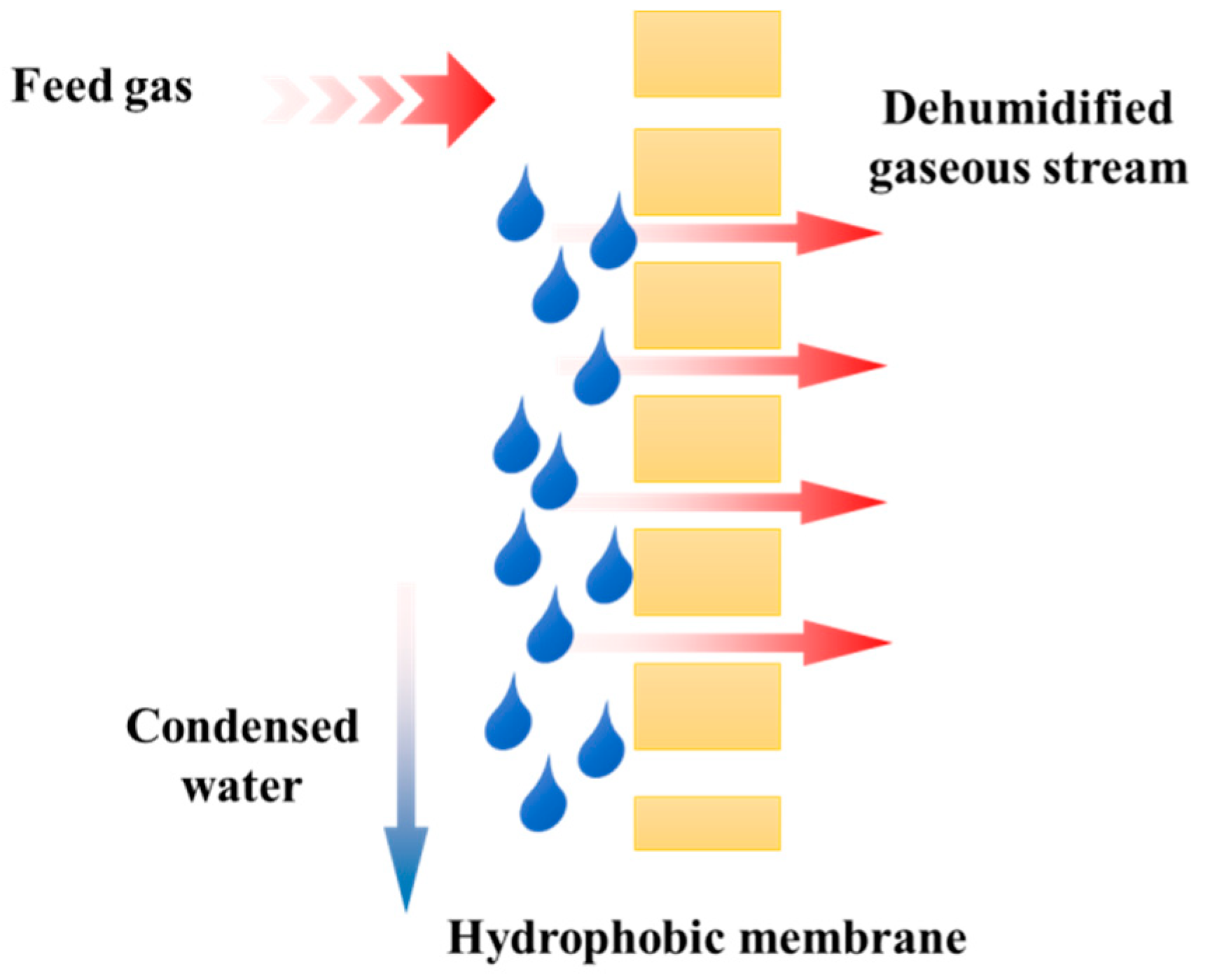
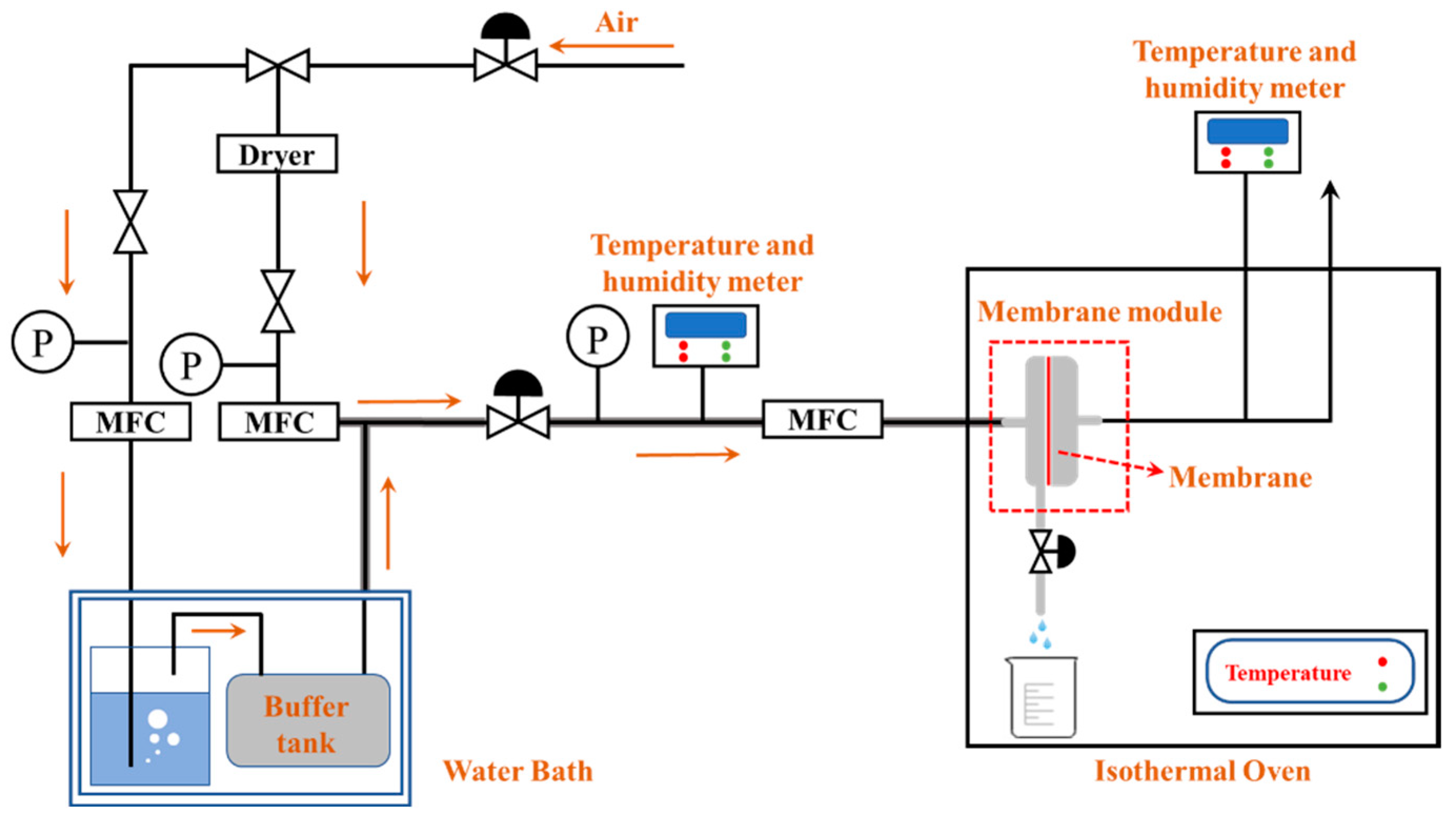
2.3.3. Membrane Condenser
3. Results and Discussions
3.1. Phase Diagram
3.2. Membrane Characterization
3.2.1. Morphology and Topography of ECTFE Membrane
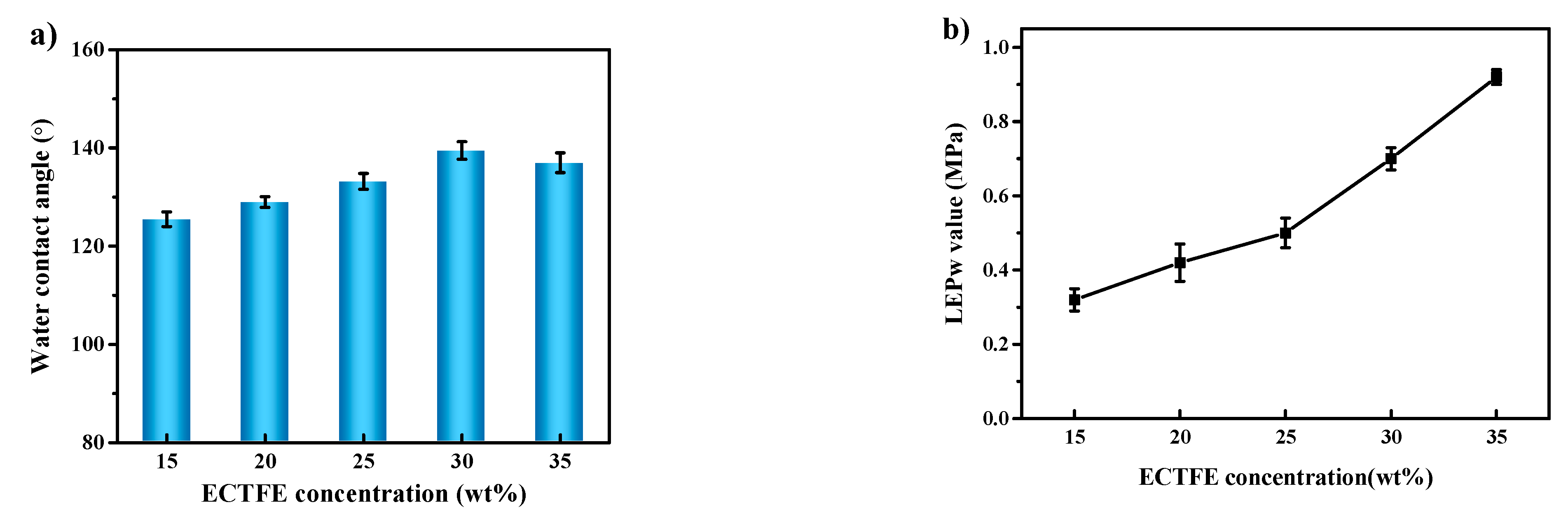
3.2.2. Hydrophobicity Measurement of ECTFE Membrane
3.2.3. Mean Pore Size and Porosity of ECTFE Membrane
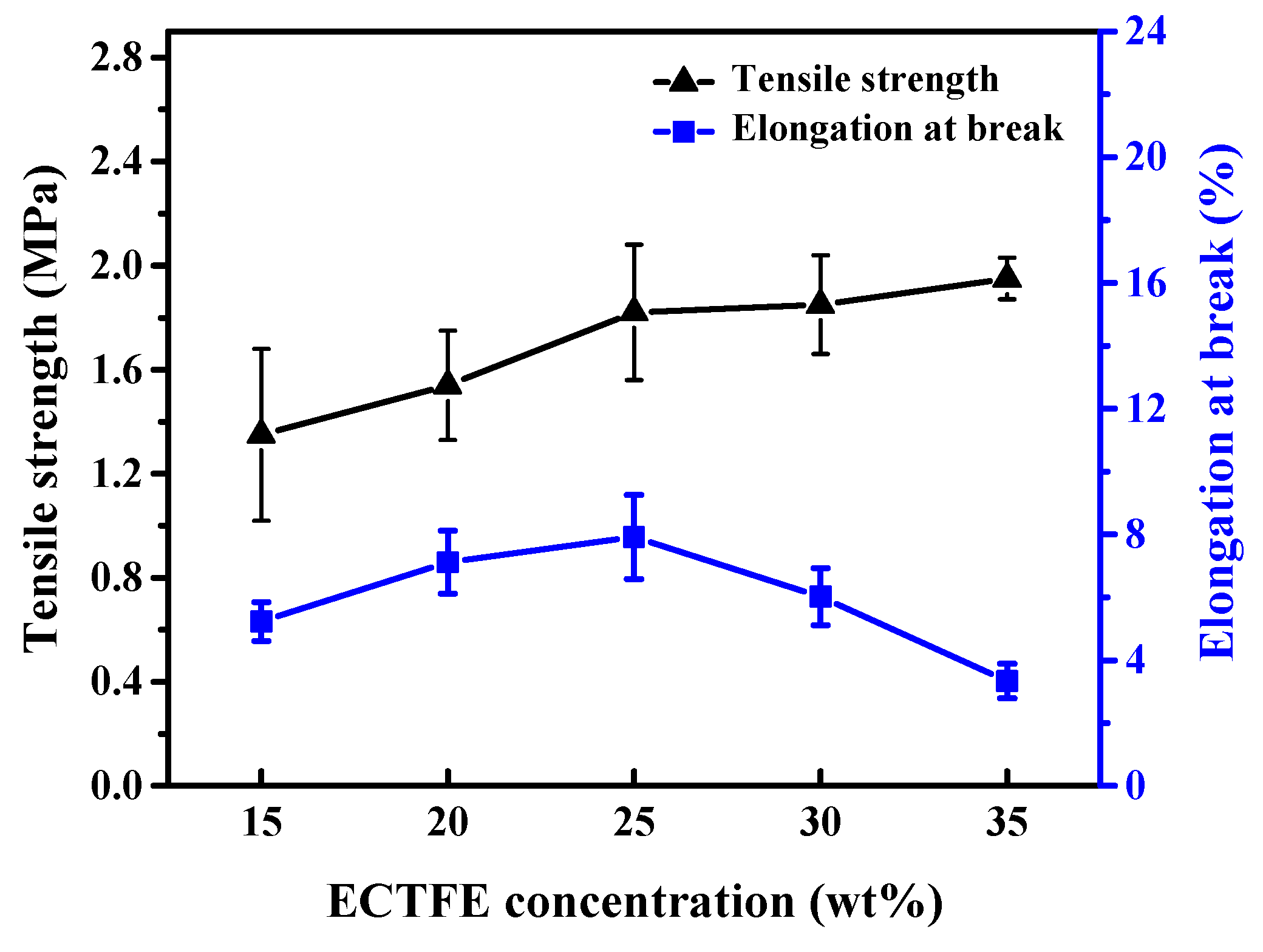
3.2.4. Mechanical Properties of ECTFE Membrane
3.3. Dehydration by Membrane Condenser
4. Conclusions
- (1)
- ECTFE membranes are successfully prepared by thermally induced phase separation methods using DnOP as the diluent. The theoretical calculation of the solubility parameters indicates that the ECTFE and DnOP have good compatibility. The phase diagram of the ECTFE/DnOP binary system proves the existence of one liquid–liquid phase separation zone within the prepared polymer concentration range where a final bi-continuous structure can be obtained. Moreover, this can be clearly observed from the SEM images.
- (2)
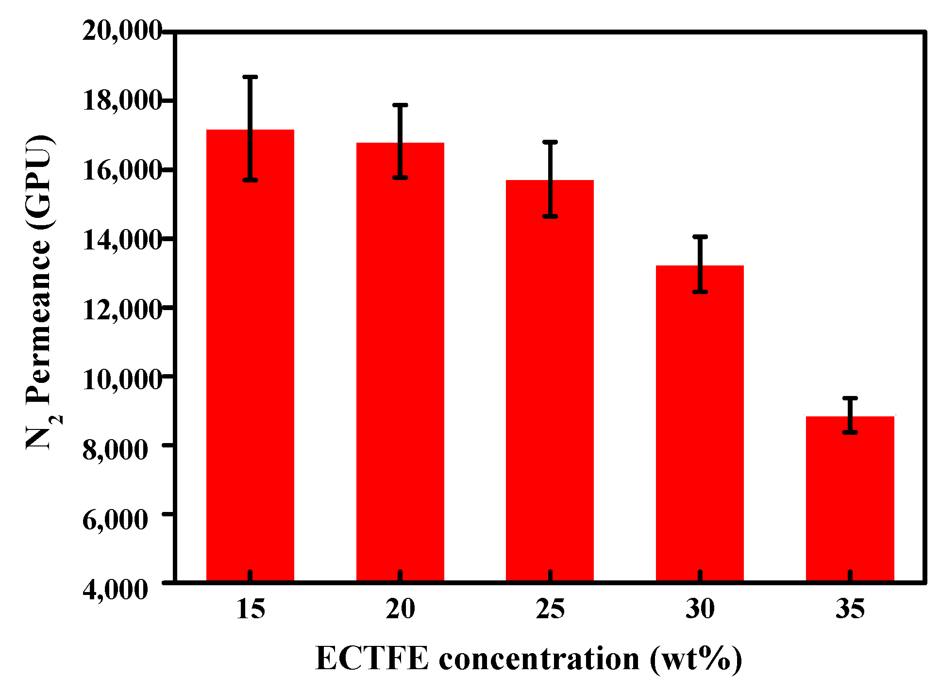
- The surface SEM images of the ECTFE membranes present a plexiform structure with high roughness. A rough hydrophobic interface is desired as it is relatively easier for the condensed droplets to slip off the membrane surface during the membrane condenser process. The cross-section SEM images for almost all of the prepared ECTFE membranes present a bi-continuous structure. However, when the ECTFE concentration increases to over 35 wt%, the overall membrane structure become dense. As a result, the average pore size and porosity of the prepared membranes decrease.
- (3)
- The maximum contact angle of nearly 140° is obtained for membranes with an ECTFE content of 30 wt%. The LEPw value of this membrane is 0.71 MPa, which is higher than the required operating pressure of the membrane condenser.
- (4)
- The membrane with the ECTFE content of 30 wt% showed the best performance in the membrane condenser process, with a water recovery of 17.6% and a condensate yield of 1.86 kg m−2 h−1.
Author Contributions
Funding
Institutional Review Board Statement
Informed Consent Statement
Data Availability Statement
Acknowledgments
Conflicts of Interest
References
- Zhong, W.W.; Guo, L.W.; Ji, C.; Dong, G.X.; Li, S. Membrane distillation for zero liquid discharge during treatment of wastewater from the industry of traditional Chinese medicine: A review. Environ. Chem. Lett. 2021, 19, 2317–2330. [Google Scholar] [CrossRef]
- Goh, P.S.; Naim, R.; Rahbari-Sisakht, M.; Ismail, A.F. Modification of membrane hydrophobicity in membrane contactors for environmental remediation. Sep. Purif. Technol. 2019, 227, 115721. [Google Scholar] [CrossRef]
- Macedonio, F.; Brunetti, A.; Barbieri, G.; Drioli, E. Membrane condenser as a new technology for water recovery from humidified “Waste” gaseous streams. Ind. Eng. Chem. Res. 2013, 52, 1160–1167. [Google Scholar] [CrossRef]
- Jeong, K.; Kessen, M.J.; Bilirgen, H.; Levy, E.K. Analytical modeling of water condensation in condensing heat exchanger. Int. J. Heat. Mass. Tran. 2010, 53, 2361–2368. [Google Scholar] [CrossRef]
- Cao, J.Y.; Pan, J.; Cui, Z.L.; Wang, Z.H.; Wang, X.Z.; Drioli, E. Improving efficiency of PVDF membranes for recovering water from humidified gas streams through membrane condenser. Chem. Eng. Sci. 2019, 210, 115234. [Google Scholar] [CrossRef]
- Lin, C.X.; Wang, D.X.; Bao, A.N. Numerical modeling and simulation of condensation heat transfer of a flue gas in a bundle of transport membrane tubes. Int. J. Heat Mass Transf. 2013, 60, 41–50. [Google Scholar] [CrossRef]
- Kim, J.F.; Park, A.; Kim, S.-J.; Lee, P.; Cho, Y.; Park, H.; Nam, S.; Park, Y. Harnessing clean water from power plant emissions using membrane condenser technology. ACS Sustain. Chem. Eng. 2018, 6, 6425–6433. [Google Scholar] [CrossRef]
- Cui, Z.L.; Drioli, E.; Lee, Y.M. Recent progress in fluoropolymers for membranes. Prog. Polym. Sci. 2014, 39, 164–198. [Google Scholar] [CrossRef]
- Teoh, M.M.; Chung, T.S.; Yeo, Y.S. Dual-layer PVDF/PTFE composite hollow fibers with a thin macrovoid-free selective layer for water production via membrane distillation. Chem. Eng. J. 2011, 171, 684–691. [Google Scholar] [CrossRef]
- Figoli, A.; Ursino, C.; Galiano, F.; Di Nicolò, E.; Campanelli, P.; Carnevale, M.C.; Criscuoli, A. Innovative hydrophobic coating of perfluoropolyether (PFPE) on commercial hydrophilic membranes for DCMD application. J. Membr. Sci. 2017, 522, 192–201. [Google Scholar] [CrossRef]
- Zheng, G.T.; Yao, L.; You, X.F.; Liao, Y.; Wang, R.; Huang, J.J. Effects of different secondary nano-scaled roughness on the properties of omniphobic membranes for brine treatment using membrane distillation. J. Membr. Sci. 2021, 620, 118918. [Google Scholar] [CrossRef]
- Zhang, W.; Hu, B.Y.; Wang, Z.; Li, B.A. Fabrication of omniphobic PVDF composite membrane with dual-scale hierarchical structure via chemical bonding for robust membrane distillation. J. Membr. Sci. 2021, 622, 119038. [Google Scholar] [CrossRef]
- Abdullah, N.; Yusof, N.; Ismail, A.F.; Lau, W.J. Insights into metal-organic frameworks-integrated membranes for desalination process: A review. Desalination 2021, 500, 114867. [Google Scholar] [CrossRef]
- Wang, Y.T.; Han, M.Y.; Liu, L.; Yao, J.M.; Han, L. Beneficial CNT intermediate layer for membrane fluorination toward robust superhydrophobicity and wetting resistance in membrane distillation. ACS Appl. Mater. Interfaces 2020, 12, 20942–20954. [Google Scholar] [CrossRef] [PubMed]
- Gupta, I.; Chakraborty, J.; Roy, S.; Farinas, E.T.; Mitra, S. Nanocarbon immobilized membranes for generating bacteria and endotoxin free water via membrane distillation. Sep. Purif. Technol. 2021, 259, 118133. [Google Scholar] [CrossRef]
- Xu, K.; Cai, Y.C.; Hassankiadeh, N.T.; Cheng, Y.M.; Li, X.; Wang, X.Z.; Wang, Z.H.; Drioli, E.; Cui, Z.L. ECTFE membrane fabrication via TIPS method using ATBC diluent for vacuum membrane distillation. Desalination 2019, 456, 13–22. [Google Scholar] [CrossRef]
- Liu, G.; Pan, J.; Xu, X.L.; Wang, Z.H.; Cui, Z.L. Preparation of ECTFE porous membrane with a green diluent TOTM and performance in VMD process. J. Membr. Sci. 2020, 612, 118375. [Google Scholar] [CrossRef]
- Pan, J.; Xiao, C.F.; Huang, Q.L.; Liu, H.L.; Hu, J. ECTFE porous membranes with conveniently controlled microstructures for vacuum membrane distillation. J. Mater. Chem. A 2015, 3, 23549–23559. [Google Scholar] [CrossRef]
- Pan, J.; Ma, W.Y.; Huang, L.L.; Li, R.Z.; Huang, Q.L.; Xiao, C.F.; Jiang, Z.H. Fabrication and characterization of ECTFE hollow fiber membranes via low-temperature thermally induced phase separation (L-TIPS). J. Membr. Sci. 2021, 634, 119429. [Google Scholar] [CrossRef]
- Anari, Z.; Sengupta, A.; Wickramasinghe, S.R. Surface oxidation of Ethylenechlorotrifluoroethylene (ECTFE) membrane for the treatment of real produced water by membrane distillation. Int. J. Env. Res. Public Health 2018, 15, 1561. [Google Scholar] [CrossRef] [Green Version]
- Gryta, M. The study of performance of polyethylene chlorinetrifluoroethylene membranes used for brine desalination by membrane distillation. Desalination 2016, 398, 52–63. [Google Scholar] [CrossRef]
- Ursino, C.; Ounifi, I.; Di Nicolo, E.; Cheng, X.Q.; Shao, L.; Zhang, Y.; Drioli, E.; Criscuoli, A.; Figoli, A. Development of non-woven fabric-based ECTFE membranes for direct contact membrane distillation application. Desalination 2021, 500, 114879. [Google Scholar] [CrossRef]
- Al-Furaiji, M.; Benes, N.; Nijmeijer, A.; McCutcheon, J.R. Application of direct contact membrane distillation for treating high salinity solutions: Impact of membrane structure and chemistry. Desalin. Water Treat. 2018, 136, 31–38. [Google Scholar] [CrossRef]
- Anari, Z.; Mai, C.; Sengupta, A.; Howard, L.; Brownmiller, C.; Wickramasinghe, S.R. Combined osmotic and membrane distillation for concentration of anthocyanin from muscadine pomace. J. Food Sci. 2019, 84, 2199–2208. [Google Scholar] [CrossRef]
- Gardiner, J. Fluoropolymers: Origin, Production, and Industrial and Commercial Applications. Aust. J. Chem. 2015, 68, 13–22. [Google Scholar] [CrossRef]
- Halar ECTFE coating system from Solvay. Surf. Coat. Int. 2019, 102, 66.
- Kabutoya, T.; Mitsuhashi, T.; Watanabe, T.; Nakagami, R.; Hata, Y.; Shimada, K.; Kario, K. The Relationship between Optimization for Cardiac Resynchronization Therapy by Measurement of dp/dt and the Middle-to-long-term Prognosis of Heart Failure Patients. J. Arrhythmia 2011, 27, 208–213. [Google Scholar] [CrossRef]
- Tan, S.; Li, J.; Gao, G.; Li, H.; Zhang, Z. Synthesis of fluoropolymer containing tunable unsaturation by a controlled dehydrochlorination of P(VDF-co-CTFE) and its curing for high performance rubber applications. J. Mater. Chem. 2012, 22, 18496–18504. [Google Scholar] [CrossRef]
- Cui, Z.L.; Cheng, Y.M.; Xu, K.; Yue, J.; Zhou, Y.; Li, X.G.; Wang, Q.; Sun, S.P.; Wang, Y.; Wang, X.Z.; et al. Wide liquid-liquid phase separation region enhancing tensile strength of poly(vinylidene fluoride) membranes via TIPS method with a new diluent. Polymer 2018, 141, 46–53. [Google Scholar] [CrossRef]
- Sousa, R.E.; Nunes-Pereira, J.; Ferreira, J.C.C.; Costa, C.M.; Machado, A.V.; Silva, M.M.; Lanceros-Mendez, S. Microstructural variations of poly(vinylidene fluoride co-hexafluoropropylene) and their influence on the thermal, dielectric and piezoelectric properties. Polym. Test. 2014, 40, 245–255. [Google Scholar] [CrossRef]
- Ramaswamy, S.; Greenberg, A.R.; Krantz, W.B. Fabrication of poly (ECTFE) membranes via thermally induced phase separation. J. Membr. Sci. 2002, 210, 175–180. [Google Scholar] [CrossRef]
- Roh, I.J.; Ramaswamy, S.; Krantz, W.B.; Greenberg, A.R. Poly(ethylene chlorotrifluoroethylene) membrane formation via thermally induced phase separation (TIPS). J. Membr. Sci. 2010, 362, 211–220. [Google Scholar] [CrossRef]
- Simone, S.; Figoli, A.; Santoro, S.; Galiano, F.; Alfadul, S.M.; Al-Harbi, O.A.; Drioli, E. Preparation and characterization of ECTFE solvent resistant membranes and their application in pervaporation of toluene/water mixtures. Sep. Purif. Technol. 2012, 90, 147–161. [Google Scholar] [CrossRef]
- Drioli, E.; Santoro, S.; Simone, S.; Barbieri, G.; Brunetti, A.; Macedonio, F.; Figoli, A. ECTFE membrane preparation for recovery of humidified gas streams using membrane condenser. React. Funct. Polym. 2014, 79, 1–7. [Google Scholar] [CrossRef]
- Karkhanechi, H.; Rajabzadeh, S.; Di Nicolo, E.; Usuda, H.; Shaikh, A.R.; Matsuyama, H. Preparation and characterization of ECTFE hollow fiber membranes via thermally induced phase separation (TIPS). Polymer 2016, 97, 515–524. [Google Scholar] [CrossRef]
- Santoro, S.; Drioli, E.; Figoli, A. Development of novel ECTFE coated PP composite hollow-fiber membranes. Coatings 2016, 6, 40. [Google Scholar] [CrossRef] [Green Version]
- Pan, J.; Xiao, C.F.; Huang, Q.L.; Wang, C.; Liu, H.L. Fabrication and properties of poly(ethylene chlorotrifluoroethylene) membranes via thermally induced phase separation (TIPS). RSC Adv. 2015, 5, 45249–45257. [Google Scholar] [CrossRef]
- Zhou, B.; Li, Q.; Tang, Y.H.; Lin, Y.K.; Wang, X.L. Preparation of ECTFE membranes with bicontinuous structure via TIPS method by a binary diluent. Desalin. Water Treat. 2016, 57, 17646–17657. [Google Scholar] [CrossRef]
- Zhou, B.; Lin, Y.K.; Ma, W.Z.; Tang, Y.H.; Tian, Y.; Wang, X.L. Preparation of ethylene chlorotrifluoroethylene co-polymer membranes via thermally induced phase separation. Chem. J. Chin. Univ. 2012, 33, 2585–2590. [Google Scholar] [CrossRef]
- Pan, J.; Xiao, C.F.; Huang, Q.L.; Liu, H.L.; Zhang, T. ECTFE hybrid porous membrane with hierarchical micro/nano-structural surface for efficient oil/water separation. J. Membr. Sci. 2017, 524, 623–630. [Google Scholar] [CrossRef]
- Ursino, C.; Simone, S.; Donato, L.; Santoro, S.; De Santo, M.P.; Drioli, E.; Di Nicolo, E.; Figoli, A. ECTFE membranes produced by non-toxic diluents for organic solvent filtration separation. RSC Adv. 2016, 6, 81001–81012. [Google Scholar] [CrossRef]
- Kim, J.F.; Kim, J.H.; Lee, Y.M.; Drioli, E. Thermally induced phase separation and electrospinning methods for emerging membrane applications: A review. AlChE J. 2016, 62, 461–490. [Google Scholar] [CrossRef]
- Cui, Z.L.; Hassankiadeh, N.T.; Lee, S.Y.; Lee, J.M.; Woo, K.T.; Sanguineti, A.; Arcella, V.; Lee, Y.M.; Drioli, E. Poly(vinylidene fluoride) membrane preparation with an environmental diluent via thermally induced phase separation. J. Membr. Sci. 2013, 444, 223–236. [Google Scholar] [CrossRef]
- Cui, Z.Y.; Xu, Y.Y.; Zhu, L.P.; Wang, J.Y.; Zhu, B.K. Investigation on PVDF-HFP microporous membranes prepared by TIPS process and their application as polymer electrolytes for lithium ion batteries. Ionics 2009, 15, 469–476. [Google Scholar] [CrossRef]
- Ji, G.L.; Zhu, L.P.; Zhu, B.K.; Zhang, C.F.; Xu, Y.Y. Structure formation and characterization of PVDF hollow fiber membrane prepared via TIPS with diluent mixture. J. Membr. Sci. 2008, 319, 264–270. [Google Scholar] [CrossRef]
- Franken, A.C.M.; Nolten, J.A.M.; Mulder, M.H.V.; Bargeman, D.; Smolders, C.A. Wetting criteria for the applicability of membrane distillation. J. Membr. Sci. 1987, 33, 315–328. [Google Scholar] [CrossRef] [Green Version]
- Siyal, M.I.; Khan, A.A.; Lee, C.K.; Kim, J.O. Surface modification of glass fiber membranes by fluorographite coating for desalination of concentrated saline water with humic acid in direct-contact membrane distillation. Sep. Purif. Technol. 2018, 205, 284–292. [Google Scholar] [CrossRef]
- Wang, T.; Yue, M.; Qi, H.; Feron, P.H.M.; Zhao, S. Transport membrane condenser for water and heat recovery from gaseous streams: Performance evaluation. J. Membr. Sci. 2015, 484, 10–17. [Google Scholar] [CrossRef]
- Macedonio, F.; Brunetti, A.; Barbieri, G.; Drioli, E. Membrane condenser configurations for water recovery from waste gases. Sep. Purif. Technol. 2017, 181, 60–68. [Google Scholar] [CrossRef]


| ECTFE Code | Solvent (s) | Membrane Type | Ref. |
|---|---|---|---|
| Halar® 901 | DBP, DOP, TCB | Flat sheet | [31] |
| Halar® 901 | DBP | Flat sheet | [32] |
| Halar® 901 | NMP | Flat sheet | [33] |
| Halar® 901 | GTA | Flat sheet | [34] |
| Halar® 901 | GTA/DEP | Hollow fiber | [35] |
| Halar® 901 | NMP | Hollow fiber | [36] |
| Halar® 901 | DEHA/DEP | Hollow fiber | [19] |
| Halar® 902 | DOA | Flat sheet | [37] |
| Halar® 902 | DBS/TPP | Hollow fiber | [38] |
| Halar® 902 | DEHA/DEP | Flat sheet | [18] |
| Halar® 902 | ATBC | Flat sheet | [16] |
| Halar® 902 | DEP | Flat sheet | [39] |
| Halar® 902 | DEHA/DEP | Flat sheet | [40] |
| Halar® 902 | TOTM | Flat sheet | [17] |
| Halar® 901 and LMP ECTFE | DEA | Flat sheet | [41] |
| ECTFE | DnOP | ||
|---|---|---|---|
Molecular structure: | Molecular structure: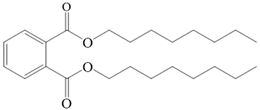 | ||
| Density (g/cm3) | 1.68 | Flash point (°C) | 218 |
| Melting point (°C) | 242 | Spoiling point (°C) | 340 |
| Parameters | Value |
|---|---|
| The effective membrane area (cm2) | 12.56 |
| Feed gas temperature (°C) | 55 |
| Feed gas relative humidity (%RH) | 100 |
| Feed gas flow rate (L·min−1) | 1.5 |
| Pressure difference (kPa) | 10 |
| Temperature difference between gas and membrane surface (°C) | 35 |
| (MPa1/2) | (MPa1/2) | (MPa1/2) | R (MPa1/2) | |
|---|---|---|---|---|
| ECTFE | 19.5 | 7.3 | 1.7 | - |
| DBP | 17.8 | 8.6 | 4.1 | 4.36 |
| DEP | 17.6 | 9.6 | 4.5 | 5.25 |
| GTA | 16.5 | 4.5 | 9.1 | 9.93 |
| ATBC | 16.02 | 9.1 | 8.55 | 10.86 |
| TOTM | 16.66 | 8.55 | 6.03 | 8.54 |
| DnOP | 16.6 | 6.03 | 3.1 | 5.97 |
| ECTFE Content in Membranes | SEM-Surface | SEM-Cross-Section | 3D AFM Image Size: 5μm × 5μm |
|---|---|---|---|
| 15 wt% (thickness: 0.253 ± 0.011 mm) | 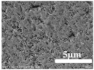 | 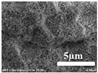 | 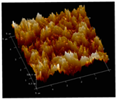 |
| 20 wt% (thickness: 0.271 ± 0.021 mm) |  |  | 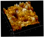 |
| 25 wt% (thickness: 0.287 ± 0.019 mm) |  |  |  |
| 30 wt% (thickness: 0.308 ± 0.015 mm) | 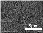 |  |  |
| 35 wt% (thickness: 0.324 ± 0.026 mm) |  | 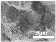 | 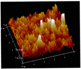 |
| ECTFE Content in Membranes | Rmax (nm) | Rq (nm) | Ra (nm) |
|---|---|---|---|
| 15 wt% | 836 | 67.7 | 48.37 |
| 20 wt% | 621 | 79.9 | 61.6 |
| 25 wt% | 765 | 87.7 | 67.5 |
| 30 wt% | 1193 | 121 | 92.4 |
| 35 wt% | 812 | 95.5 | 77 |
| ECTFE Content in Membranes | Mean Pore Size (μm) | Porosity (%) |
|---|---|---|
| 15 wt% | 0.105 ± 0.004 | 60.8 ± 1.2 |
| 20 wt% | 0.105 ± 0.011 | 59.8 ± 1.0 |
| 25 wt% | 0.099 ± 0.007 | 61.1 ± 0.5 |
| 30 wt% | 0.097 ± 0.005 | 60.2 ± 1.5 |
| 35 wt% | 0.082 ± 0.008 | 56.8 ± 0.5 |
Publisher’s Note: MDPI stays neutral with regard to jurisdictional claims in published maps and institutional affiliations. |
© 2022 by the authors. Licensee MDPI, Basel, Switzerland. This article is an open access article distributed under the terms and conditions of the Creative Commons Attribution (CC BY) license (https://creativecommons.org/licenses/by/4.0/).
Share and Cite
Pan, J.; Chen, K.; Cui, Z.; Bamaga, O.; Albeirutty, M.; Alsaiari, A.O.; Macedonio, F.; Drioli, E. Preparation of ECTFE Porous Membrane for Dehumidification of Gaseous Streams through Membrane Condenser. Membranes 2022, 12, 65. https://doi.org/10.3390/membranes12010065
Pan J, Chen K, Cui Z, Bamaga O, Albeirutty M, Alsaiari AO, Macedonio F, Drioli E. Preparation of ECTFE Porous Membrane for Dehumidification of Gaseous Streams through Membrane Condenser. Membranes. 2022; 12(1):65. https://doi.org/10.3390/membranes12010065
Chicago/Turabian StylePan, Jun, Kun Chen, Zhaoliang Cui, Omar Bamaga, Mohammed Albeirutty, Abdulmohsen Omar Alsaiari, Francesca Macedonio, and Enrico Drioli. 2022. "Preparation of ECTFE Porous Membrane for Dehumidification of Gaseous Streams through Membrane Condenser" Membranes 12, no. 1: 65. https://doi.org/10.3390/membranes12010065
APA StylePan, J., Chen, K., Cui, Z., Bamaga, O., Albeirutty, M., Alsaiari, A. O., Macedonio, F., & Drioli, E. (2022). Preparation of ECTFE Porous Membrane for Dehumidification of Gaseous Streams through Membrane Condenser. Membranes, 12(1), 65. https://doi.org/10.3390/membranes12010065