
Preparation, Characterization, and Activity of Pd/PSS-Modified Membranes in the Low Temperature Dry Reforming of Methane with and without Addition of Extra Steam

 ,
,  and
and 
Abstract
:
1. Introduction
2. Materials and Methods
2.1. Synthesis of Catalysts
2.2. Synthesis of Membranes
2.2.1. Preparation of PSS Modified Supports
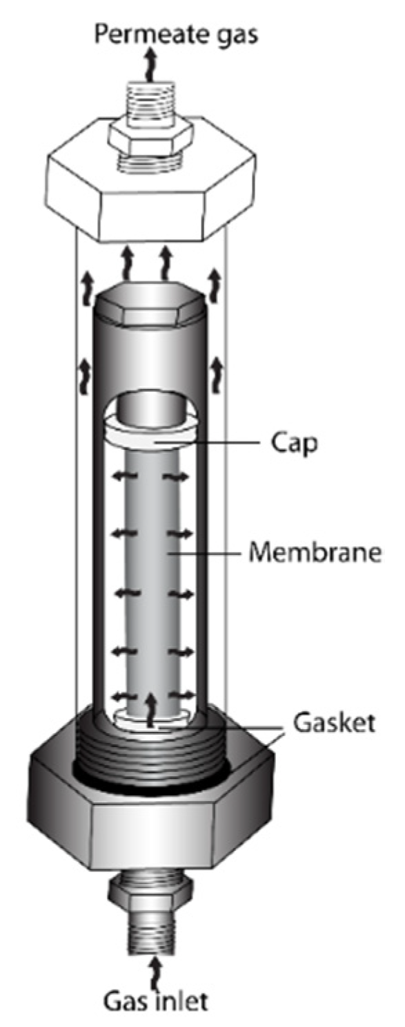
2.2.2. Synthesis of Pd Dense Membranes
2.3. Characterization
2.3.1. Catalysts
2.3.2. Membranes
2.4. Activity Measurements in the Low Temperature Dry Reforming of Methane
2.4.1. Conventional Reactor
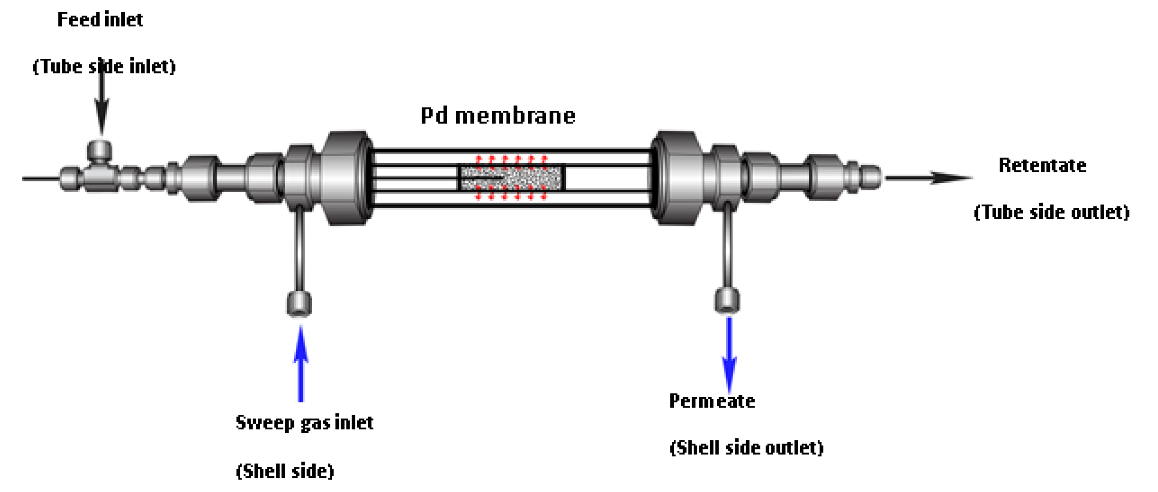
2.4.2. Pd Membrane Reactor
3. Results and Discussion
3.1. Characterization of Catalysts
3.2. Characterization of PSS Supports and Composite Pd Membranes
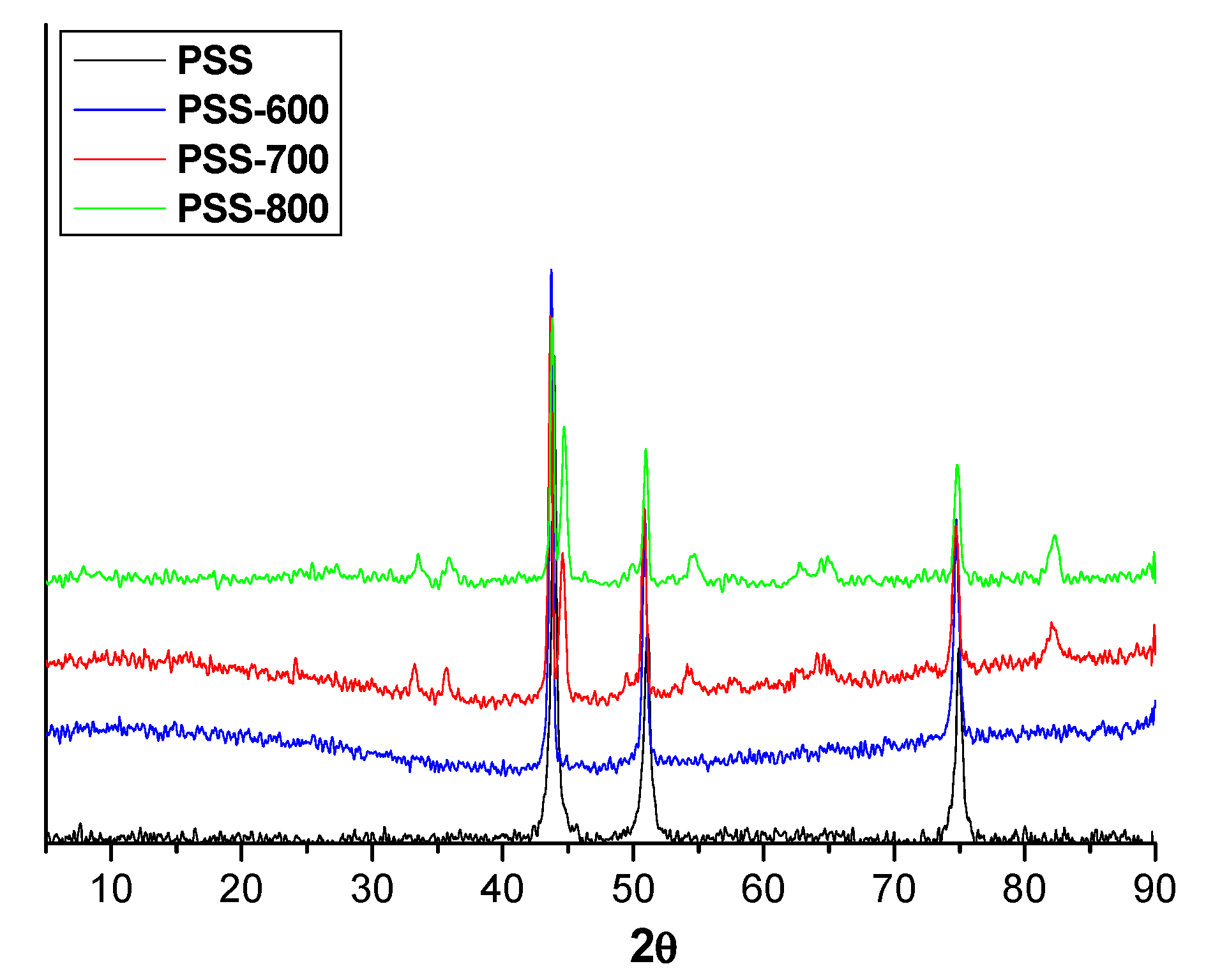
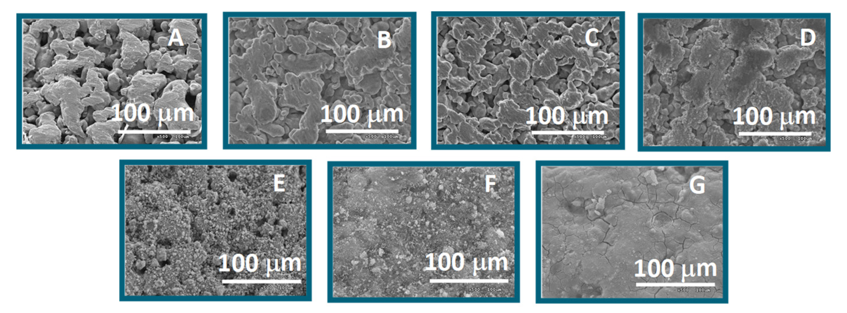
3.2.1. Supports
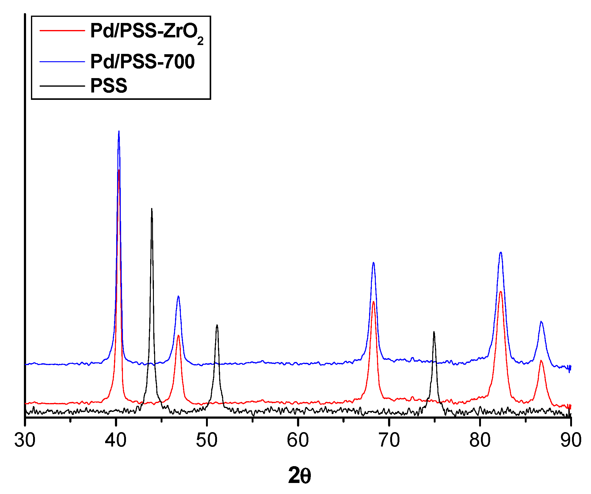
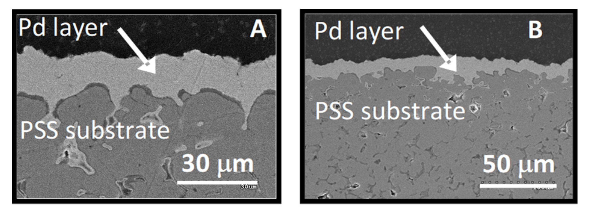
3.2.2. Pd Membranes
3.2.3. Permeation Measurements
3.3. Activity in the Low-Temperature DRM
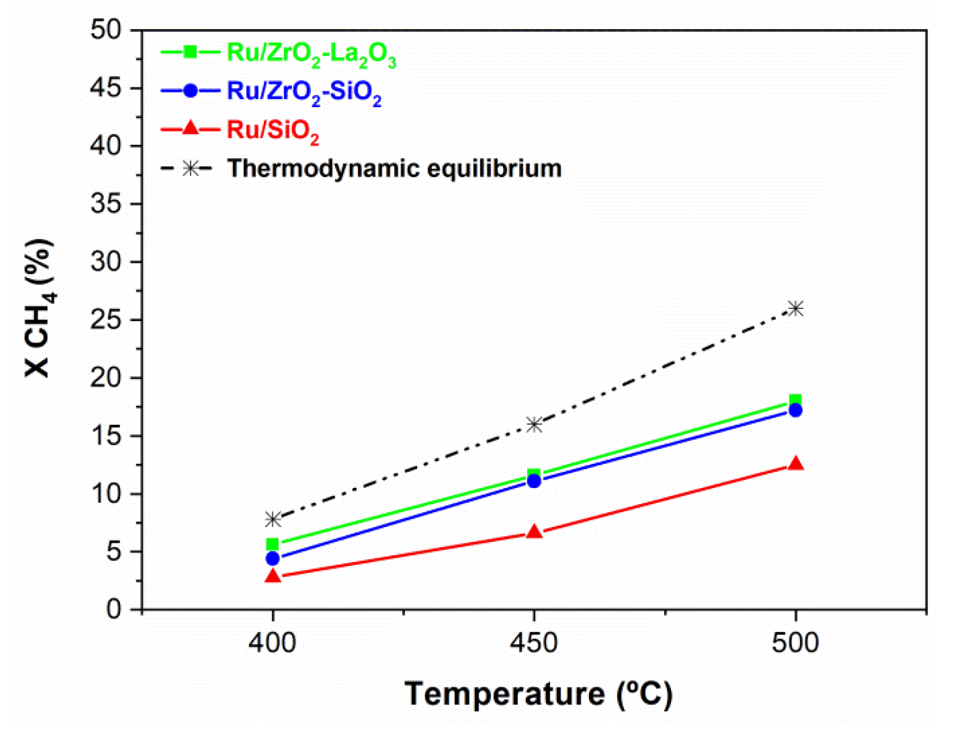
3.3.1. Activity Measurements Performed in the Conventional Reactor
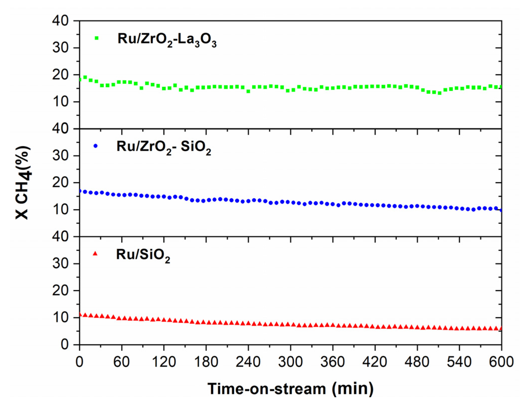
Stability Measurements Performed in the CR
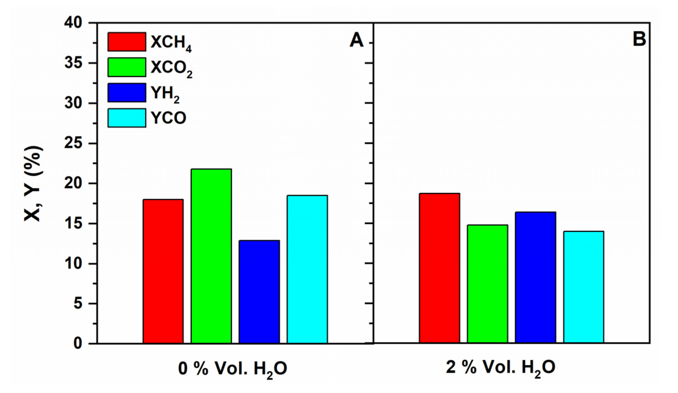
Influence of Co-Feeding Water in the CR
3.3.2. Tests Performed in the Multifunctional Pd MR
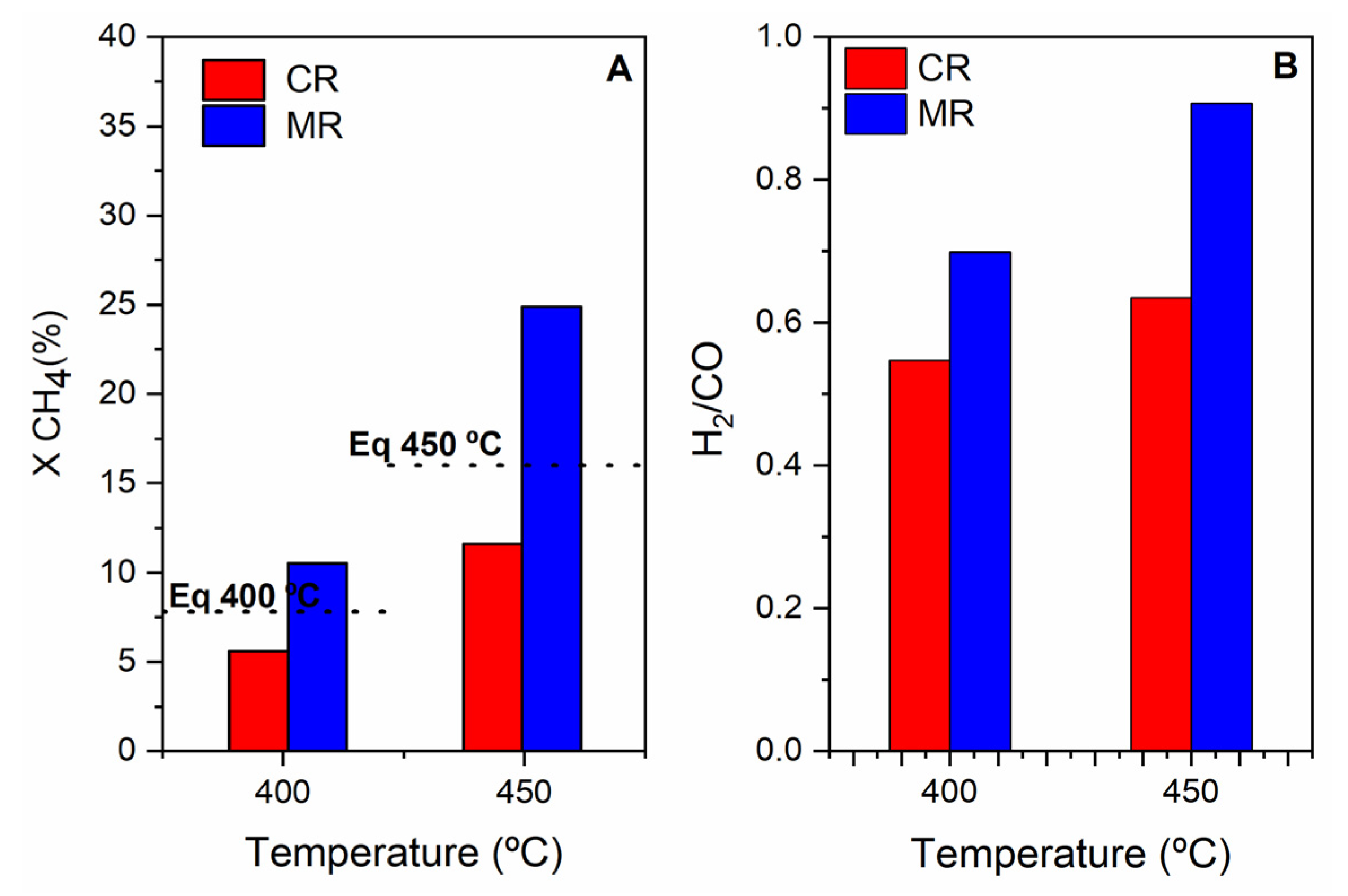
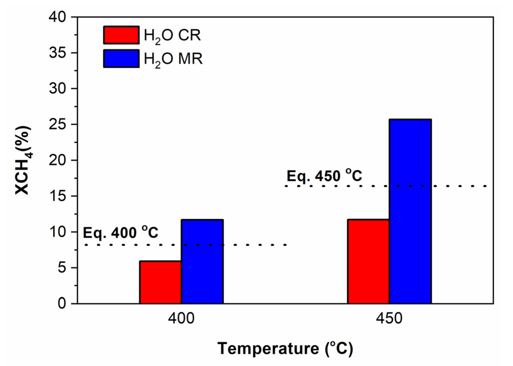
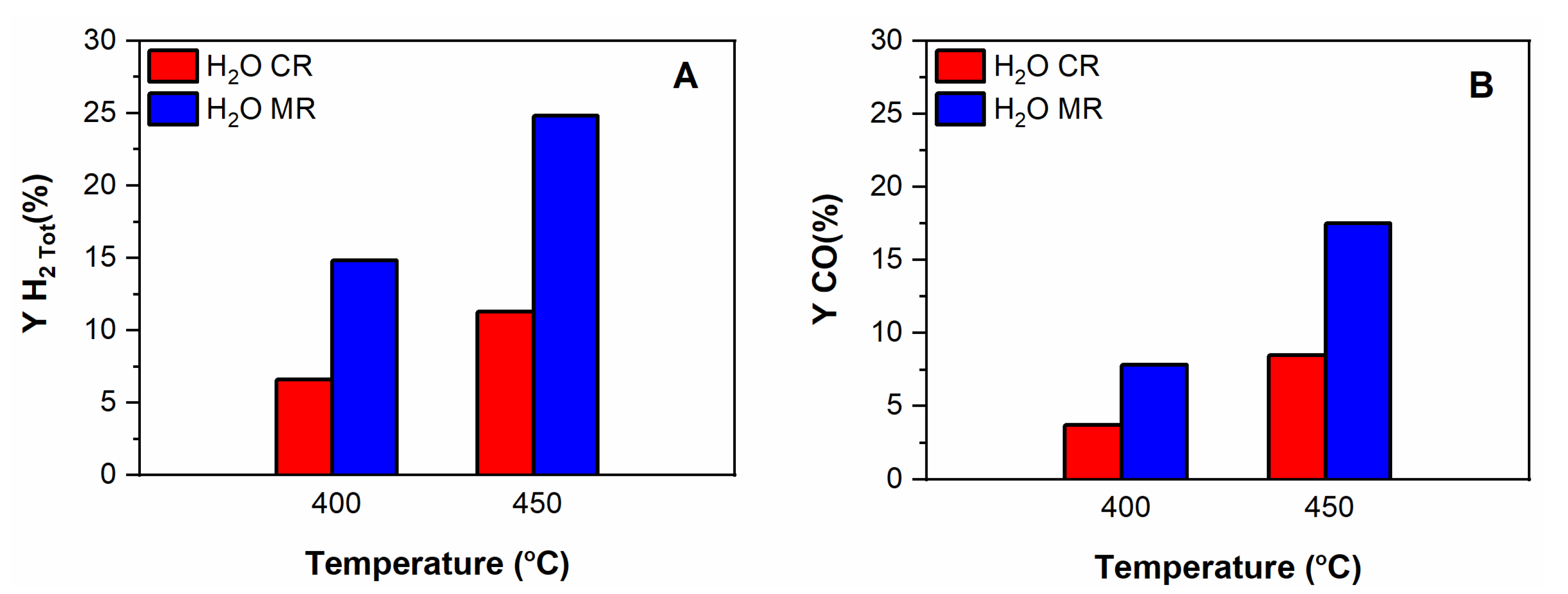
The Effect of the Pd Membrane: CR vs. MR
- (a)
- Without steam in the feed
- (b)
- With steam in the feed
4. Conclusions
Author Contributions
Funding
Institutional Review Board Statement
Informed Consent Statement
Conflicts of Interest
References
- Anzelmo, B.; Wilcox, J.; Liguori, S. Natural gas steam reforming reaction at low temperature and pressure conditions for hydrogen production via Pd/PSS membrane reactor. J. Membr. Sci. 2017, 522, 343–350. [Google Scholar] [CrossRef]
- Habib, M.A.; Harale, A.; Paglieri, S.; Alrashed, F.S.; Al-Sayoud, A.; Rao, M.V.; Nemitallah, M.A.; Hossain, S.; Hussien, M.; Ali, A.; et al. Palladium-Alloy Membrane Reactors for Fuel Reforming and Hydrogen Production: A Review. Energy Fuels 2021, 35, 5558–5593. [Google Scholar] [CrossRef]
- Ward, T.L.; Dao, T. Model of hydrogen permeation behavior in palladium membranes. J. Membr. Sci. 1999, 153, 211–231. [Google Scholar] [CrossRef]
- Kiadehi, A.D.; Taghizadeh, M.; Rami, M.D. Preparation of Pd/SAPO-34/PSS composite membranes for hydrogen separation: Effect of crystallization time on the zeolite growth on PSS support. J. Ind. Eng. Chem. 2020, 81, 206–218. [Google Scholar] [CrossRef]
- Yepes, D.; Cornaglia, L.M.; Irusta, S.; Lombardo, E.A. Different oxides used as diffusion barriers in composite hydrogen permeable membranes. J. Membr. Sci. 2006, 274, 92–101. [Google Scholar] [CrossRef]
- Mateos-Pedrero, C.; Soria, M.A.; Rodríguez-Ramos, I.; Guerrero-Ruiz, A. Modifications of porous stainless steel previous to the synthesis of Pd membranes. Stud. Surf. Sci. Catal. 2010, 175, 779–783. [Google Scholar] [CrossRef]
- Shu, J.; Adnot, A.; Grandjean, B.P.A.; Kaliaguine, S. Structurally stable composite Pd-Ag alloy membranes: Introduction of a diffusion barrier. Thin Solid Film. 1996, 286, 72–79. [Google Scholar] [CrossRef]
- Augustine, A.S.; Mardilovich, I.P.; Kazantzis, N.K.; Hua Ma, Y. Durability of PSS-supported Pd-membranes under mixed gas and water–gas shift conditions. J. Membr. Sci. 2012, 415-416, 213–220. [Google Scholar] [CrossRef]
- Qiao, A.; Zhang, K.; Tian, Y.; Xie, L.; Luo, H.; Lin, Y.S.; Li, Y. Hydrogen separation through palladium–copper membranes on porous stainless steel with sol–gel derived ceria as diffusion barrier. Fuel 2010, 89, 1274–1279. [Google Scholar] [CrossRef]
- Bosko, M.L.; Miller, J.B.; Lombardo, E.A.; Gellman, A.J.; Cornaglia, L.M. Surface characterization of Pd-Ag composite membranes after annealing at various temperatures. J. Membr. Sci. 2011, 369, 267–276. [Google Scholar] [CrossRef]
- Tong, J.H.; Shirai, R.; Kashima, Y.; Matsumura, Y. Preparation of a pinhole-free Pd-Ag membrane on a porous metal support for pure hydrogen separation. J. Membr. Sci. 2005, 260, 84–89. [Google Scholar] [CrossRef]
- Tarditi, A.; Gerboni, C.; Cornaglia, L. PdAu membranes supported on top of vacuum-assisted ZrO2-modified porous stainless steel substrates. J. Membr. Sci. 2013, 428, 1–10. [Google Scholar] [CrossRef]
- Huang, Y.; Dittmeyer, R. Preparation of thin palladium membranes on a porous support with rough surface. J. Membr. Sci. 2007, 302, 160–170. [Google Scholar] [CrossRef]
- Wei, L.; Yu, J.; Hu, X.; Huang, Y. Fabrication of H2-permeable palladium membranes based on pencil-coated porous stainless steel substrate. Int. J. Hydrogen Energy 2012, 37, 13007–13012. [Google Scholar] [CrossRef]
- Calles, J.A.; Sanz, R.; Alique, D. Influence of the type of siliceous material used as intermediate layer in the preparation of hydrogen selective palladium composite membranes over a porous stainless steel support. Int. J. Hydrogen Energy 2012, 37, 6030–6042. [Google Scholar] [CrossRef]
- Jabbour, K. Tuning combined steam and dry reforming of methane for “metgas” production: A thermodynamic approach and state-of-the-art catalysts. J. Energy Chem. 2020, 48, 54–91. [Google Scholar] [CrossRef]
- Parente, M.; Soria, M.A.; Madeira, L.M. Hydrogen and/or syngas production through combined dry and steam reforming of biogas in a membrane reactor: A thermodynamic study. Renew. Energy 2020, 157, 1254–1264. [Google Scholar] [CrossRef]
- Ferreira-Aparicio, P.; Rodríguez-Ramos, I.; Guerrero-Ruiz, A. On the applicability of membrane technology to the catalysed dry reforming of methane. Appl. Catal. A Gen. 2002, 237, 239–252. [Google Scholar] [CrossRef]
- Oyama, S.T.; Hacarlioglu, P.; Gu, Y.; Lee, D. Dry reforming of methane has no future for hydrogen production: Comparison with steam reforming at high pressure in standard and membrane reactors. Int. J. Hydrogen Energy 2012, 37, 10444–10450. [Google Scholar] [CrossRef]
- Siang, T.J.; Pham, T.L.M.; Cuong, N.V.; Phuong, P.T.T.; Phuc, N.H.H.; Truong, Q.D.; Vo, D.-V.N. Combined steam and CO2 reforming of methane for syngas production over carbon-resistant boron-promoted Ni/SBA-15 catalysts. Microporous Mesoporous Mater. 2018, 262, 122–132. [Google Scholar] [CrossRef]
- Soria, M.A.; Mateos-Pedrero, C.; Guerrero-Ruiz, A.; Rodríguez-Ramos, I. Thermodynamic and experimental study of combined dry and steam reforming of methane on Ru/ ZrO2-La2O3 catalyst at low temperature. Int. J. Hydrogen Energy 2011, 36, 15212–15220. [Google Scholar] [CrossRef]
- Kumar, N.; Shojaee, M.; Spivey, J.J. Catalytic bi-reforming of methane: From greenhouse gases to syngas. Curr. Opin. Chem. Eng. 2015, 9, 8–15. [Google Scholar] [CrossRef] [Green Version]
- Jabbour, K.; Massiani, P.; Davidson, A.; Casale, S.; Hassan, N.E. Ordered mesoporous “one-pot” synthesized Ni-Mg(Ca)-Al2O3 as effective and remarkably stable catalysts for combined steam and dry reforming of methane (CSDRM). Appl. Catal. B Environ. 2017, 201, 527–542. [Google Scholar] [CrossRef] [Green Version]
- Soria, M.A.; Mateos-Pedrero, C.; Rodríguez-Ramos, I.; Guerrero-Ruiz, A. Catalytic steam reforming of methane under conditions of applicability with Pd membranes over supported Ru catalysts. Catal. Today 2011, 171, 126–131. [Google Scholar] [CrossRef]
- Ferreira-Aparicio, P.; Guerrero-Ruiz, A.; Rodríguez-Ramos, I. Comparative study at low and medium reaction temperatures of syngas production by methane reforming with carbon dioxide over silica and alumina supported catalysts. Appl. Catal. A Gen. 1998, 170, 177–187. [Google Scholar] [CrossRef]
- Jang, W.-J.; Jeong, D.-W.; Shim, J.-O.; Kim, H.-M.; Roh, H.-S.; Son, I.H.; Lee, S.J. Combined steam and carbon dioxide reforming of methane and side reactions: Thermodynamic equilibrium analysis and experimental application. Appl. Energy 2016, 173, 80–91. [Google Scholar] [CrossRef]
- Ozkara-Aydinoglu, S.; Aksoylu, A.E. CO2 reforming of methane over Pt-Ni/Al2O3 catalysts: Effects of catalyst composition, and water and oxygen addition to the feed. Int. J. Hydrogen Energy 2011, 36, 2950–2959. [Google Scholar] [CrossRef]
- Faroldi, B.; Bosko, M.L.; Múnera, J.; Lombardo, E.; Cornaglia, L. Comparison of Ru/La2O2CO3 performance in two different membrane reactors for hydrogen production. Catal. Today 2013, 213, 135–144. [Google Scholar] [CrossRef]
- Nishimura, A.; Takada, T.; Ohata, S.; Kolhe, M.L. Biogas Dry Reforming for Hydrogen through Membrane Reactor Utilizing Negative Pressure. Fuels 2021, 2, 194–209. [Google Scholar] [CrossRef]
- García-García, F.R.; Soria, M.A.; Mateos-Pedrero, C.; Guerrero-Ruiz, A.; Rodríguez-Ramos, I.; Li, K. Dry reforming of methane using Pd-based membrane reactors fabricated from different substrates. J. Membr. Sci. 2013, 435, 218–225. [Google Scholar] [CrossRef]
- Bosko, M.L.; Múnera, J.F.; Lombardo, E.A.; Cornaglia, L.M. Dry reforming of methane in membrane reactors using Pd and Pd–Ag composite membranes on a NaA zeolite modified porous stainless steel support. J. Membr. Sci. 2010, 364, 17–26. [Google Scholar] [CrossRef]
- Caravella, A.; Brunetti, A.; Grandinetti, M.; Barbieri, G. Dry Reforming of Methane in a Pd-Ag Membrane Reactor: Thermodynamic and Experimental Analysis. ChemEngineering 2018, 2, 48. [Google Scholar] [CrossRef] [Green Version]
- Durán, P.; Sanz-Martínez, A.; Soler, J.; Menéndez, M.; Herguido, J. Pure hydrogen from biogas: Intensified methane dry reforming in a two-zone fluidized bed reactor using permselective membranes. Chem. Eng. J. 2019, 370, 772–781. [Google Scholar] [CrossRef] [Green Version]
- Coronel, L.; Múnera, J.F.; Lombardo, E.A.; Cornaglia, L.M. Pd based membrane reactor for ultra pure hydrogen production through the dry reforming of methane. Experimental and modeling studies. Appl. Catal. A Gen. 2011, 400, 185–194. [Google Scholar] [CrossRef]
- Raybold, T.M.; Huff, M.C. Analyzing enhancement of CO2, reforming of CH4, in Pd membrane reactors. AIChE J. 2002, 48, 1051–1061. [Google Scholar] [CrossRef]
- Gallucci, F.; Paturzo, L.; Famà, A.; Basile, A. Experimental Study of the Methane Steam Reforming Reaction in a Dense Pd/Ag Membrane Reactor. Ind. Eng. Chem. Res. 2004, 43, 928–933. [Google Scholar] [CrossRef]
- Iulianelli, A.; Alavi, M.; Bagnato, G.; Liguori, S.; Wilcox, J.; Rahimpour, M.R.; Eslamlouyan, R.; Anzelmo, B.; Basile, A. Supported Pd-Au Membrane Reactor for Hydrogen Production: Membrane Preparation, Characterization and Testing. Molecules 2016, 21, 581. [Google Scholar] [CrossRef] [PubMed] [Green Version]
- Iulianelli, A.; Liguori, S.; Huang, Y.; Basile, A. Model biogas steam reforming in a thin Pd-supported membrane reactor to generate clean hydrogen for fuel cells. J. Power Sources 2015, 273, 25–32. [Google Scholar] [CrossRef]
- Sato, T.; Suzuki, T.; Aketa, M.; Ishiyama, Y.; Mimura, K.; Itoh, N. Steam reforming of biogas mixtures with a palladium membrane reactor system. Chem. Eng. Sci. 2010, 65, 451–457. [Google Scholar] [CrossRef]
- Di Marcoberardino, G.; Foresti, S.; Binotti, M.; Manzolini, G. Potentiality of a biogas membrane reformer for decentralized hydrogen production. Chem. Eng. Process. Process Intensif. 2018, 129, 131–141. [Google Scholar] [CrossRef]
- Tong, J.; Suda, H.; Haraya, K.; Matsumura, Y. A novel method for the preparation of thin dense Pd membrane on macroporous stainless steel tube filter. J. Membr. Sci. 2005, 260, 10–18. [Google Scholar] [CrossRef]
- Ma, Y.H.; Mardilovich, P.P.; She, Y. Hydrogen Gas-Extraction Module and Method of Fabrication. U.S. Patent 6,152,987, 28 November 2000. [Google Scholar]
- Soria, M.A.; Mateos-Pedrero, C.; Marín, P.; Ordóñez, S.; Guerrero-Ruiz, A.; Rodríguez-Ramos, I. Kinetic analysis of the Ru/SiO2-catalyzed low temperature methane steam reforming. Appl. Catal. A Gen. 2012, 413–414, 366–374. [Google Scholar] [CrossRef]
- Peña, M.A.; Carr, D.M.; Yeung, K.L.; Varma, A. Ethylene epoxidation in a catalytic packed-bed membrane reactor. Chem. Eng. Sci. 1998, 53, 3821–3834. [Google Scholar] [CrossRef]
- Bosko, M.L.; Ojeda, F.; Lombardo, E.A.; Cornaglia, L.M. NaA zeolite as an effective diffusion barrier in composite Pd/PSS membranes. J. Membr. Sci. 2009, 331, 57–65. [Google Scholar] [CrossRef]
- Sieverts, A.; Krumbhaar, W. Solubility of gases in metals and alloys. Ber. Deut. Chem. Ges. 1910, 43, 893–900. [Google Scholar] [CrossRef] [Green Version]
- Sanz, R.; Calles, J.A.; Alique, D.; Furones, L.; Ordóñez, S.; Marín, P.; Corengia, P.; Fernandez, E. Preparation, testing and modelling of a hydrogen selective Pd/YSZ/SS composite membrane. Int. J. Hydrogen Energy 2011, 36, 15783–15793. [Google Scholar] [CrossRef]
- Dan, M.; Mihet, M.; Borodi, G.; Lazar, M.D. Combined steam and dry reforming of methane for syngas production from biogas using bimodal pore catalysts. Catal. Today 2021, 366, 87–96. [Google Scholar] [CrossRef]
- Lee, B.; Lim, H. Parametric studies for CO2 reforming of methane in a membrane reactor as a new CO2 utilization process. Korean J. Chem. Eng. 2017, 34, 199–205. [Google Scholar] [CrossRef]
- Irusta, S.; Múnera, J.; Carrara, C.; Lombardo, E.A.; Cornaglia, L.M. A stable, novel catalyst improves hydrogen production in a membrane reactor. Appl. Catal. A Gen. 2005, 287, 147–158. [Google Scholar] [CrossRef]
- Múnera, J.; Faroldi, B.; Frutis, E.; Lombardo, E.; Cornaglia, L.; Carrazán, S.G. Supported Rh nanoparticles on CaO–SiO2 binary systems for the reforming of methane by carbon dioxide in membrane reactors. Appl. Catal. A Gen. 2014, 474, 114–124. [Google Scholar] [CrossRef]


| Sample | Modification of PSS Support | a Dp (µm) | ΔHe Permeation b (%) |
|---|---|---|---|
| PSS-600 | Oxidation at 600 °C for 12 h | 4.4 | −17 |
| PSS-700 | Oxidation at 700 °C for 12 h | 4.5 | −54 |
| PSS-800 | Oxidation at 800 °C for 12 h | 4.6 | −76 |
| PSS-SiO2 | Coating with SiO2 | 4.6 | −68 |
| PSS-Al2O3 | Coating with Al2O3 | 4.8 | −23 |
| PSS-ZrO2 | Coating with ZrO2 | 4.6 | −52 |
| Component | Silica Coating | Alumina Coating | Zirconia Coating |
|---|---|---|---|
| Alkoxide | TEOS | Al-isopropoxide | Zr-tetrabutoxide |
| Peptizing agent | NH3 | HNO3 | HNO3 |
| Solvent | Ethanol | Isopropanol | Butanol |
| * Alkoxide: H2O | 0.25:9 | 1.2:105 | 0.04:8 |
| * Alcohol: Acid or base | 5.5:0.45 | 6:0.1 | 0.25:0.02 |
| Temperature (°C) | 50 | 80 | 60 |
| Component | Pd Bath |
|---|---|
| Pd(NH3)4Cl2·H2O | 4 g/L |
| NH4OH (28%) | 198 mL/L |
| Na2EDTA.2H2O | 40 g/L |
| N2H4 (1 M) | 5.6 mL/L |
| pH | 10–11 |
| Temperature | 50 °C |
| Sample | He Permeation * (m3/m2 h) | Modification of PSS Support | Pd Thickness Gravimetric (μm) |
|---|---|---|---|
| Pd/PSS-ZrO2 | dense | Coating with ZrO2 | 17 |
| Pd/PSS-700 | dense | Oxidation-700 °C; 12 h | 20 |
| Catalyst | TPR (°C) | Nads (μmol/gcat) | D (%) | d (nm) | * B. E. (eV) | * XPS at. Ratio (%) | |
|---|---|---|---|---|---|---|---|
| Ru3d5/2 | Ru/Si | Ru/Zr | |||||
| Ru/SiO2 | 150 | 62 | 16 | 8.4 | 280.4 | 0.009 | — |
| Ru/ZrO2-SiO2 | 159 | 112 | 28 | 4.7 | 280.9 | — | 0.05 |
| Ru/ZrO2-La2O3 | 161 | 85 | 24 | 5.3 | 280.6 | — | 0.08 |
| H2O Vol. % in the Feed | XCH4 | XCO2 | YH2 | YCO | H2/CO Ratio |
|---|---|---|---|---|---|
| 0 | 24.9 | 25.2 | 19.4 | 21.4 | 0.91 |
| 2 | 25.7 | 18.5 | 24.8 | 17.5 | 1.41 |
Publisher’s Note: MDPI stays neutral with regard to jurisdictional claims in published maps and institutional affiliations. |
© 2021 by the authors. Licensee MDPI, Basel, Switzerland. This article is an open access article distributed under the terms and conditions of the Creative Commons Attribution (CC BY) license (https://creativecommons.org/licenses/by/4.0/).
Share and Cite
Mateos-Pedrero, C.; Soria, M.A.; Guerrero-Ruíz, A.; Rodríguez-Ramos, I. Preparation, Characterization, and Activity of Pd/PSS-Modified Membranes in the Low Temperature Dry Reforming of Methane with and without Addition of Extra Steam. Membranes 2021, 11, 518. https://doi.org/10.3390/membranes11070518
Mateos-Pedrero C, Soria MA, Guerrero-Ruíz A, Rodríguez-Ramos I. Preparation, Characterization, and Activity of Pd/PSS-Modified Membranes in the Low Temperature Dry Reforming of Methane with and without Addition of Extra Steam. Membranes. 2021; 11(7):518. https://doi.org/10.3390/membranes11070518
Chicago/Turabian StyleMateos-Pedrero, Cecilia, Miguel A. Soria, Antonio Guerrero-Ruíz, and Inmaculada Rodríguez-Ramos. 2021. "Preparation, Characterization, and Activity of Pd/PSS-Modified Membranes in the Low Temperature Dry Reforming of Methane with and without Addition of Extra Steam" Membranes 11, no. 7: 518. https://doi.org/10.3390/membranes11070518
APA StyleMateos-Pedrero, C., Soria, M. A., Guerrero-Ruíz, A., & Rodríguez-Ramos, I. (2021). Preparation, Characterization, and Activity of Pd/PSS-Modified Membranes in the Low Temperature Dry Reforming of Methane with and without Addition of Extra Steam. Membranes, 11(7), 518. https://doi.org/10.3390/membranes11070518